JP4635646B2 - Crop cleaning equipment - Google Patents
Crop cleaning equipment Download PDFInfo
- Publication number
- JP4635646B2 JP4635646B2 JP2005055069A JP2005055069A JP4635646B2 JP 4635646 B2 JP4635646 B2 JP 4635646B2 JP 2005055069 A JP2005055069 A JP 2005055069A JP 2005055069 A JP2005055069 A JP 2005055069A JP 4635646 B2 JP4635646 B2 JP 4635646B2
- Authority
- JP
- Japan
- Prior art keywords
- cleaning
- conveyor
- crop
- end side
- storage tank
- Prior art date
- Legal status (The legal status is an assumption and is not a legal conclusion. Google has not performed a legal analysis and makes no representation as to the accuracy of the status listed.)
- Expired - Fee Related
Links
Images


Landscapes
- Cleaning In General (AREA)
- Apparatuses For Bulk Treatment Of Fruits And Vegetables And Apparatuses For Preparing Feeds (AREA)
Description
本発明は、収穫した人参や大根等を洗浄する洗浄装置に関するものである。 The present invention relates to a cleaning apparatus for cleaning harvested carrots, radishes and the like.
上記の技術分野に関して、例えば特開2005−21753号公報には、搬送コンベアで持ち上げ搬送した作物を複数の洗浄ロールを備える洗浄装置で洗浄する技術が開示されている。
特許文献1においては、搬送コンベアで洗浄装置に収穫作物を投入する構成のため、作物に付着する泥が洗浄装置の洗浄始端側に集中して堆積するため、洗浄ロールの耐久性が低下しやすいものであった。
In
また、特許文献1においては搬送コンベアと洗浄装置とが並列して配置しているため、搬送コンベアと洗浄装置との間にはシュータ等を別個に設ける必要がある。そのため、搬送コンベアと洗浄装置とは直列で隣接して配置することが望ましい。
In
しかしながら、上記の配置構成では、搬送コンベアと洗浄装置との間にスペースが形成されないため、メンテナンス性が低下してしまう。
また、搬送コンベアと洗浄装置との間に設けたシュータを通過する際に作物が傷付いてしまう問題があると共に、シュータが洗浄装置に接触するとシュータや洗浄装置が傷つくという問題がある。
本発明は、収穫した作物を洗浄装置で洗浄する前に粗洗浄できる構成にすることで洗浄ロールの耐久性等を向上させるものでありながら、粗洗浄した泥を回収しやすく、搬送中の作物が傷付きにくくすることを課題とする。
However, in the arrangement described above, since the space is not formed between the transfer conveyor and the cleaning device, maintainability is degraded.
In addition, there is a problem that the crop is damaged when passing through the shooter provided between the conveyor and the cleaning device, and there is a problem that the shooter and the cleaning device are damaged when the shooter contacts the cleaning device.
The invention, yet those of durability of the cleaning roll is improved by the configuration capable rough cleaning before washing the harvested crops in the cleaning device, rather easy to rough cleaning mud recovered, during transport The challenge is to make crops less susceptible to damage .
また、搬送コンベアと洗浄装置とを直列に隣接して配置するものでありながら、洗浄装置の洗浄始端側にスペースを形成し、メンテナンスをし易くすることを課題とする。 It is another object of the present invention to form a space on the cleaning start end side of the cleaning device to facilitate maintenance while arranging the conveyor and the cleaning device adjacent in series.
本発明は、上記課題を解決するために次の技術的手段を用いる。
すなわち、請求項1記載の発明においては、作物と水とを収容可能な収容タンク(A)を設け、該収容タンク(A)内に作物を持ち上げ搬送する搬送コンベア(B)を設け、該搬送コンベア(B)で持ち上げ搬送した作物を収容して洗浄する洗浄装置(C)を設けた作物洗浄装置において、前記搬送コンベア(B)の搬送始端部を略平坦に形成すると共に、搬送途中から搬送終端側にかけて斜め上方向に向かって形成し、前記搬送コンベア(B)を搬送終端側を支点にして搬送始端側が回動する構成とし、該搬送コンベア(B)の搬送途中から搬送終端側に沿って収容タンク(A)の底部に斜め上方向の傾斜部(3)を形成し、前記洗浄装置(C)内に作物を洗浄する複数の洗浄ロール(15)を略U字状に配置して洗浄列(K1,K2)を形成し、該洗浄ロール(15)の洗浄始端側と収容タンク(A)の傾斜部(3)とを隣接させて空間部(T)を形成し、該洗浄ロール(15)を駆動させる駆動モータ(29)を洗浄ロール(15)よりも下方で且つ空間部(T)に突出させて配置し、前記搬送コンベア(B)の搬送始端側に軸(15)を支点に回動する回動傾斜板(16)を設け、該回動傾斜板(16)に吊りフック(18)を設けたことを特徴とする作物洗浄装置とする。
The present invention uses the following technical means in order to solve the above problems.
That is, in the first aspect of the present invention, the crop water and can accommodate a storage tank (A) is provided, the transport conveyor (B) provided for transporting lift the crop into the housing tank (A), the in the cleaning device (C) crop cleaning device provided with the housing the conveying crops lifted by the transport conveyor (B) to wash, as well as substantially flat form conveying starting end of the conveyor (B), the transport way formed obliquely upward direction toward the conveying end side from the conveying starting end in the fulcrum transporting terminating said conveyor (B) is configured to rotate, transporting terminating end from being conveyed in the conveying conveyor (B) A slanting upwardly inclined portion (3) is formed at the bottom of the storage tank (A), and a plurality of cleaning rolls (15) for cleaning the crops are arranged in a substantially U shape in the cleaning device (C). And wash column (K1, K2) Drive forms, the inclined portion of the cleaning starting end and holding tank of the cleaning rolls (15) (A) (3) and the by adjacency to form a space portion (T), thereby driving the wash roll (15) The motor (29) is disposed below the cleaning roll (15) and protrudes into the space (T), and is rotated around the shaft (15) as a fulcrum at the transport start end side of the transport conveyor (B). An inclined plate (16) is provided, and a hanging hook (18) is provided on the rotating inclined plate (16) .
請求項2記載の発明においては、前記搬送コンベア(B)から排出される作物を洗浄装置(C)に案内する案内シュート(14)を搬送コンベア(B)の搬送終端側に設け、該案内シュート(14)を弾性体で形成したことを特徴とする請求項1記載の作物洗浄装置とする。
In invention of
請求項3記載の発明においては、前記洗浄列(K1,K2)を二列設け、複数の洗浄ロール(15)の洗浄始端側に駆動スプロケット(25a)をそれぞれ設け、複数の駆動スプロケット(25a)に各々第1チェーン(26)を無端状に巻回し、二列の洗浄列(K1,K2)に一つの駆動モータ(29)からの駆動力を伝動する第2チェーン(28)を設けたことを特徴とする請求項1または2記載の作物洗浄装置とする。
According to a third aspect of the present invention, two rows of the cleaning rows (K1, K2) are provided, a driving sprocket (25a) is provided on each cleaning start end side of the plurality of cleaning rollers (15), and a plurality of driving sprockets (25a) are provided. Each of the first chains (26) is wound endlessly, and a second chain (28) for transmitting the driving force from one drive motor (29) is provided in the two cleaning rows (K1, K2). The crop cleaning apparatus according to
請求項1記載の発明は、収容タンク(A)内に水と作物を投入することにより、作物は水に浸かりながら搬送コンベア(B)で搬送されるため、洗浄装置(C)に作物を供給する前に粗洗浄ができるため、洗浄装置(C)の洗浄始端側に流入する泥の量が少なくなり、洗浄ロール(15)の耐久性が向上する。 According to the first aspect of the present invention, since water and crops are put into the storage tank (A), the crops are transported by the transport conveyor (B) while being immersed in water, so that the crops are supplied to the cleaning device (C). since it is rough cleaning before, the amount of mud flowing into the cleaning starting end side of the cleaning device (C) is reduced, the durability of the cleaning roll (15) is improved.
そして、搬送コンベア(B)の搬送始端側を略平坦に形成すると共に、搬送途中から搬送終端部を斜め上方に向けて形成し、この搬送コンベア(B)の傾斜に沿って収容タンク(A)の底部を斜め上方向に傾斜させて傾斜部(3)を形成することにより、搬送コンベア(B)から離れた泥は傾斜部(3)を流下して搬送コンベア(B)の搬送始端側に集中するため、作業者は収容タンク(A)内に堆積した泥を除去しやすくなる。 The transportable with feed substantially flat form conveying starting end of the conveyor (B), the transfer terminal end portion from being conveyed to form obliquely upward, holding tank (A along the inclination of the conveyor (B) bottom of by the forming the inclined portion is inclined obliquely upward direction (3)), the conveyance start of the conveyor flow down the conveyor (away mud inclined slope portions from B) (3) conveyor (B) Since it concentrates on the side, the operator can easily remove the mud accumulated in the storage tank (A).
また、収容タンク(A)の搬送終端側に形成する傾斜部(3)に洗浄装置(C)の洗浄始端側を隣接させて空間部(T)を形成し、この空間部(T)に洗浄装置(C)に駆動力を供給する駆動モータ(29)を設けたことにより、洗浄装置(C)の洗浄水や作物から除去された泥が駆動モータ(29)に飛散することを防止できるので、機体のメンテナンス性が向上する。
さらに、搬送コンベア(B)の搬送始端側に軸(15)を支点にして回動する回動傾斜板(16)を設け、この回動傾斜板(16)に吊りフック(18)を設けたことにより、回動させた回動傾斜板(16)の吊りフック(18)を吊ると選別コンベア(B)の搬送終端側を支点として搬送始端側を上方に回動させることができるので、選別コンベア(B)の搬送始端側に堆積した泥が除去しやすくなる。
請求項2記載の発明は、請求項1記載の発明の効果に加えて、搬送コンベア(B)から排出される作物を洗浄装置(C)に案内する案内シュート(14)を弾性体で構成したことにより、作物が通過する際に作物が傷付くことを防止できる。
また、搬送コンベア(B)を回動させるとき、案内シュート(14)が洗浄装置(C)に接触しても搬送コンベア(B)の回動が阻害されることがなく、また、案内シュート(14)が破損することを防止できる。
Further, a space portion (T) is formed by adjoining the cleaning start end side of the cleaning device (C) to the inclined portion (3) formed on the conveyance end side of the storage tank (A), and the space portion (T) is cleaned. By providing the drive motor (29) for supplying driving force to the device (C), it is possible to prevent the washing water of the cleaning device (C) and mud removed from the crops from being scattered to the drive motor (29). , Maintenance of the aircraft is improved.
Further, a rotating inclined plate (16) that rotates about the shaft (15) is provided on the conveying start end side of the conveying conveyor (B), and a hanging hook (18) is provided on the rotating inclined plate (16). Accordingly, when the suspension hook (18) of the rotated rotation inclined plate (16) is suspended, the conveyance start end side can be rotated upward with the conveyance end side of the selection conveyor (B) as a fulcrum. It becomes easy to remove mud accumulated on the conveyance start end side of the conveyor (B).
In addition to the effect of the invention described in
Moreover, when rotating a conveyance conveyor (B), even if a guide chute (14) contacts a washing | cleaning apparatus (C), rotation of a conveyance conveyor (B) is not inhibited, and a guidance chute ( 14) can be prevented from being damaged.
請求項3記載の発明は、請求項1または2記載の発明の効果に加えて、二列の洗浄列(K1,K2)を構成する複数の洗浄ロール(15)の洗浄始端側にそれぞれスプロケット(25a)を設け、このスプロケット(25a)に第1チェーン(26)を二列の洗浄列(K1,K2)にそれぞれ無端状に巻回することにより、複数の洗浄ロール(15)を同時に回転させることができる。
また、二列の洗浄列(K1,K2)に駆動モータ(29)の駆動力を伝動する第2チェーン(28)を設けたことにより、一つの駆動モータ(29)で二列の洗浄列(K1,K2)を駆動させることができる。
そして、駆動スプロケット(25a)と第1チェーン(26)と第2チェーン(28)を洗浄ロール(15)の搬送始端部に設けたことにより、作業者は空間部(T)に入り込んで駆動スプロケット(25a)と第1チェーン(26)と第2チェーン(28)のメンテナンス作業を行うことができる。
In addition to the effect of the invention of
Further, by providing the second chain (28) for transmitting the driving force of the drive motor (29) to the two cleaning rows (K1, K2), the two cleaning rows ( K1, K2) can be driven.
Then, by providing the drive sprocket (25a), the first chain (26), and the second chain (28) at the conveyance start end of the cleaning roll (15), the operator enters the space (T) and enters the drive sprocket. (25a), the first chain (26), and the second chain (28) can be maintained.
本発明の実施の形態について、収穫した作物を洗浄装置で洗浄した後に作物の重量毎に選別する作物洗浄選別装置に基づいて説明する。
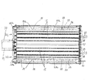
まず図1の平面図に基づいて本発明の作物洗浄選別装置全体の構成について説明する。
An embodiment of the present invention will be described on the basis of a crop washing and sorting apparatus that sorts a harvested crop by the weight of the crop after washing with a washing apparatus.
First, based on the top view of FIG. 1, the structure of the whole crop washing | cleaning selection apparatus of this invention is demonstrated.
Aは収穫した作物を投入する収容タンク、Bは収容タンクA内に投入された作物を搬送する搬送コンベア,Cは搬送コンベアBで搬送された作物を洗浄する洗浄装置,Dは洗浄装置Cで洗浄された作物を一時貯留する貯留タンク,Eは貯留タンク内の作物を搬送する第二搬送コンベア、Fは第二搬送コンベアEで搬送された作物を整列して搬送する整列搬送装置、Gは整列搬送装置で搬送された作物を重量ごとに選別する作物選別装置である。 A is a storage tank for feeding harvested crops, B is a transport conveyor that transports the crops that are thrown into the storage tank A, C is a cleaning device that cleans the crops transported by the transport conveyor B, and D is a cleaning device C. A storage tank for temporarily storing the washed crop, E is a second transport conveyor for transporting the crop in the storage tank, F is an alignment transport device for aligning and transporting the crop transported by the second transport conveyor E, G is This is a crop sorting device for sorting crops transported by an alignment transport device by weight.
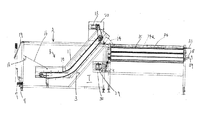
次に収容タンクA、及び搬送コンベアBについて説明する。ここで説明する始端側とは搬送コンベアBの搬送始端側を指し、終端側とは搬送コンベアBの搬送終端側を指し、それ以外は側部という。 Next, the storage tank A and the transfer conveyor B will be described. The start end side described here refers to the transfer start end side of the transfer conveyor B, the end side refers to the transfer end side of the transfer conveyor B, and the rest is referred to as a side portion.
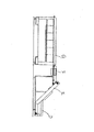
収容タンクA内は、その終端側に傾斜部3を形成し、側部はそれぞれ傾斜部4を形成し、傾斜部内側にはホッパ部1を形成している。ホッパ部1の下方には搬送コンベアBを挿入する挿入部2を形成し、挿入部2の下方、すなわち、収容タンクAの底部には挿入部2の幅Mよりも広い幅Nからなる泥溜まり部5を形成している。そのため、多くの泥を堆積できる構成としている。
泥溜まり部5の下部には水抜き穴6を形成し、水抜き穴6にはホース7を連結している。また、泥溜まり部5の下部には泥抜き通路8を設け、泥抜き通路8は開閉板9により開閉自在に構成している。
In the storage tank A, an
A drain hole 6 is formed in the lower part of the
収容タンクA内には、収容タンクA内に収容された作物を始端側から終端側に向かって斜め上がり方向に持ち上げ搬送する搬送コンベアBを設ける。搬送コンベアBは、コンベア10と、コンベア10を側方から支持する支持フレーム12と、コンベア10の搬送終端部にあってコンベア10を駆動させる駆動モータ13と、コンベア10から排出された作物を次の洗浄装置Cに案内する案内シュート14とを備えている。案内シュート14は弾性体で形成しており、隣接する洗浄装置Cの洗浄始端側の上方に配置している。
In the storage tank A, there is provided a transport conveyor B that lifts and transports the crops stored in the storage tank A in an obliquely upward direction from the start side toward the end side. The conveyor B is a
コンベア10は搬送始端側を略平坦に、搬送途中から搬送終端側にかけて斜め上方に向かって形成し、傾斜部3に並行するよう配置している。
支持フレーム12の搬送始端側には軸15を支点に回動する回動傾斜板16と、搬送コンベアBを下側から支持する支持脚17を取り付け、回動傾斜板16には吊りフック18を取り付けている。なお、19は作業者が吊りフック18に引っ掛けて持ち上げる吊り具である。また、20はモータカバー、22は収容タンクAに収穫したコンテナ(図示せず)内の作物を投入するときにコンテナを載置するための載置棒である。
The
At the conveyance start end side of the support frame 12, a rotation inclined plate 16 that rotates about a
21は搬送コンベアBを回動させる回動支点で、搬送コンベアBの搬送始端側を上下方向に回動可能に構成している。回動方法について詳述すると、作業者が回動傾斜板16を回動させ、吊り具19等をフックに18引っ掛けて持ち上げる。すると、図3に示すように回動支点21を支点に搬送コンベアBの搬送始端側が持ち上がる構成としている。
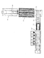
次に洗浄装置Cについて説明する。
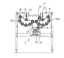
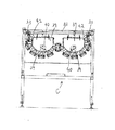
洗浄装置Cは複数の洗浄ロール15を並列して設け、洗浄ロール15の下方は開放状態に形成している。洗浄ロール15を略U字上に配列して一箇所の洗浄列K1を形成しており、本実施例では二箇所の洗浄列K1,K2を形成している。洗浄ロール15の洗浄始端側には駆動スプロケット25aをそれぞれ設け、洗浄列K1,K2毎に一本のチェーン26で巻回し、テンション27でチェーンを張る構成である。そして、洗浄ロール駆動モータ29の動力をチェーン28で各洗浄列K1,K2に伝達している。なお、30はモータ載置台で、一つの駆動モータ29が載置されており、50は一つの駆動モータ29で二つの洗浄列K1,K2を回転させるためのカウンタースプロケットである。
Next, the cleaning apparatus C will be described.
The cleaning apparatus C is provided with a plurality of
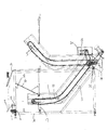
洗浄装置Cの側板31の上部には洗浄水を散水する散水装置32を形成している。散水装置32は多数の散水口33aを形成する散水パイプ33からなり、別途設ける水源(図示せず)からの水を洗浄装置Cに向かって散水口33aより散水する構成である。本実施例では水源(図示せず)と接続する散水パイプ33は洗浄終端側で分岐し、洗浄装置Cの左右の側板31それぞれに固定具35で固定している。散水口33aは洗浄始端側の口のピッチ数を多く形成することで、比較的多くの水を集中して散水できる構成としている。また、散水口33aの洗浄始端側の口の面積を他の口よりも大きくしても良い。それにより、散水量全体をできるだけ抑制しながら作物に付着する泥が多い洗浄始端側に集中して散水することができる。
On the upper part of the
34は散水パイプ33を覆うプレートで、散水口33aに対応して切欠き穴34aを形成している。このプレートは洗浄装置Cで除去された泥が散水口33aに付着して詰まることを防止し、かつ散水パイプ33に直接何らかの衝撃を与えることを防止するためのものである。
34 is a plate which covers the
プレート34の一端は洗浄装置Cの側板31側に取り付け、多端は洗浄ロール15に当接する構成としている。
洗浄装置Cの洗浄終端側には支点軸26を支点に回動する回動板37を洗浄列K1,K2毎に形成し、回動板37にはウエイト取り付け軸38とウエイト39をそれぞれ取り付けている。40は開動板37の開閉のロック及びロック解除をするロック装置である。
One end of the
A
ところで、洗浄ロール駆動モータ29は洗浄始端側より外側に向かって突出する構成である。本実施例のように収容タンクAの終端側と洗浄装置Cの洗浄始端側とを隣接して設けたときに収容タンクAの傾斜部3と洗浄装置Cの洗浄始端側との間に形成される空間部Tを利用して洗浄ロール駆動モータ29を配置する。そのため、隣接する洗浄ロール15間から流れる洗浄水や除去された泥がモータ洗浄ロール駆動モータ29にかかりにくくすることができる。また、洗浄ロール駆動モータ29が洗浄ロール15の下方に配置すると、洗浄ロール駆動モータ29と洗浄ロール15との間に除去した泥が堆積するという不具合が生じていたが本実施例のように構成することで、洗浄ロール15の下方が開放状態になるので泥が堆積することがない。
By the way, the cleaning
なお、この空間部Tは下広がりに側面視略三角形状に形成されており、作業者が駆動スプロケット25a及びチェーン26,28等をメンテナンスするときに入り込むことができる。
The space T is formed in a substantially triangular shape in a side view so as to extend downward, and can be entered when an operator performs maintenance on the drive sprocket 25a, the
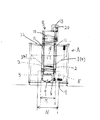
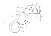
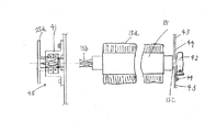
図11は洗浄ロール15の脱着の構成について説明した図である。
洗浄ロール15の洗浄始端側は角軸15bに形成し、チェーン26を卷回する駆動スプロケット25a及び軸受部41の内部に角軸15bを嵌合し、挿入・抜き出し自在に構成する。洗浄ロール15の洗浄終端側は丸軸15cを軸受けメタル42にキー(図示せず)等を解して脱着可能に嵌め合わせ、軸受けメタル42は洗浄装置Cの搬送終端側の板43にボルト44で取り付けている。なお、板43には洗浄ロール15の径よりも大きい脱着用穴44を形成しておく。
FIG. 11 is a diagram illustrating a configuration for detaching the cleaning
The cleaning
洗浄ロール15を交換するときには、ボルト44を外して軸受けメタル42を板43から取り外す。すると、軸受けメタル42は洗浄ロール15の丸軸15cから外れる。すると、洗浄ロール15は脱着用穴44から引っ張り出すことができる。反対に洗浄ロール15を取り付けるときは洗浄ロール15の角軸15bから脱着用穴44に挿入していき、角軸15cを軸受け部41に挿入し、丸軸15cとキーを軸受けメタル42に挿入し、軸受けメタル42を板にボルト締めをする。
When replacing the cleaning
このように、伝動機構45側を取り外すことなく、簡単な作業で洗浄ロール15の脱着作業を行うことができる。
作物洗浄選別装置の作用について説明する。
In this way, the detaching operation of the cleaning
The operation of the crop washing and sorting apparatus will be described.
水を張った収容タンクAに、作業者は収穫したニンジン等の作物を投入する。収容タンクA内に投入された作物は、傾斜部4及び回動傾斜板2により収容タンクAの左右中央部にある搬送コンベアBの搬送始端側に集められ、搬送コンベアBで搬送される。搬送終端側で搬送コンベアBから放出された作物は案内シュート14を通過して洗浄装置Cの各洗浄列K1,K2の洗浄始端側に落下供給される。
In the storage tank A filled with water, the worker puts harvested crops such as carrots. The crops thrown into the storage tank A are collected on the transfer start end side of the transfer conveyor B at the left and right central part of the storage tank A by the
作物を持ち上げ搬送したコンベア10が作物を放出した後、傾斜部3と対向しながら移動するときにコンベア10から落下した泥は傾斜部3により泥溜まり部5に堆積されていく。
After the
洗浄装置Cに落下供給された作物は回転する洗浄ロール15のブラシ面15aにより作物表面に付着する泥を除去されながら、洗浄終端側に向かって移送されていく。洗浄終端側に移送された作物は回動板27を押し開けながら洗浄装置Cより排出され、貯留タンクDに貯留されていく。
The crop dropped and supplied to the cleaning device C is transferred toward the cleaning end side while removing mud adhering to the crop surface by the
貯留タンクDに貯留された作物は第二搬送コンベアEにより整列搬送装置に搬送され、整列搬送装置Fで作物の姿勢を修正しながら作物選別装置Gに供給され、作物選別装置Gで重量ごとに選別される。 The crops stored in the storage tank D are transported to the aligning / conveying device by the second transporting conveyor E, supplied to the crop sorting device G while correcting the posture of the crop by the aligning / conveying device F, and the crop sorting device G for each weight. Selected.
収容タンクAの泥溜まり部5に堆積した泥を作業者が掻きだす時には、まず、作業中上に持ち上げていたホース7を寝せて収容タンクA内に張った水を排出させる。そして、作業者は回動傾斜板16を回動させ、吊り具19等をフックに18引っ掛けて持ち上げ、回動支点21を支点に搬送コンベアBの搬送始端側を持ち上げる。そして、たとえば持ち上げた搬送コンベアBと収容タンクAとの間を角棒等をかちこみ搬送コンベアBを持ち上げた状態で固定するようにする。そして、開閉板9を開放し泥溜まり部5に堆積した泥を泥抜き通路8から掻き出す。
When the worker scrapes off the mud accumulated in the
なお、このとき、案内シュート14を弾性部材にすることで、作物が通過するときに、作物に傷がつきにくい。また、搬送コンベアBを回動させるときに、案内シュート14が洗浄装置Cに当たって搬送コンベアBの回動を阻害したり、案内シュート14自体が破損し難い。
At this time, by using the
3 傾斜部
15 洗浄ロール
45 伝動機構
29 駆動モータ
A 収容タンク
B 搬送コンベア
C 洗浄装置
T 空間部
3
B Conveyor C Cleaning device T Space
Claims (3)
前記搬送コンベア(B)の搬送始端部を略平坦に形成すると共に、搬送途中から搬送終端側にかけて斜め上方向に向かって形成し、前記搬送コンベア(B)を搬送終端側を支点にして搬送始端側が回動する構成とし、該搬送コンベア(B)の搬送途中から搬送終端側に沿って収容タンク(A)の底部に斜め上方向の傾斜部(3)を形成し、前記洗浄装置(C)内に作物を洗浄する複数の洗浄ロール(15)を略U字状に配置して洗浄列(K1,K2)を形成し、該洗浄ロール(15)の洗浄始端側と収容タンク(A)の傾斜部(3)とを隣接させて空間部(T)を形成し、該洗浄ロール(15)を駆動させる駆動モータ(29)を洗浄ロール(15)よりも下方で且つ空間部(T)に突出させて配置し、前記搬送コンベア(B)の搬送始端側に軸(15)を支点に回動する回動傾斜板(16)を設け、該回動傾斜板(16)に吊りフック(18)を設けたことを特徴とする作物洗浄装置。 Crops and water and can accommodate a storage tank (A) is provided, the transport conveyor (B) provided for transporting lift the crop into the housing tank (A), the conveying crops lifted by conveying conveyor (B) in crop cleaning device provided cleaning apparatus for washing the (C) accommodated,
With substantially flat form conveying starting end of the conveyor (B), and formed obliquely upward direction toward the conveying end side from being conveyed, the conveying starting end and the fulcrum transporting terminating said conveyor (B) The inclined portion (3) in the obliquely upward direction is formed at the bottom of the storage tank (A) along the conveyance end side from the middle of conveyance of the conveyance conveyor (B), and the cleaning device (C) A plurality of cleaning rolls (15) for cleaning the crops are arranged in a substantially U shape to form a cleaning row (K1, K2). The cleaning start end side of the cleaning roll (15) and the storage tank (A) inclined portions (3) and the by adjacency forming space portion (T), and the space portion is below the wash roll drive motor (29) for driving the cleaning roll (15) (15) (T) Projecting to the end of the transport conveyor (B) Axis (15) of the rotating inclined plate to rotate (16) the fulcrum is provided, crop cleaning apparatus characterized by having a hanging hook (18) to the pivoting tilting plate (16).
Priority Applications (1)
| Application Number | Priority Date | Filing Date | Title |
|---|---|---|---|
| JP2005055069A JP4635646B2 (en) | 2005-02-28 | 2005-02-28 | Crop cleaning equipment |
Applications Claiming Priority (1)
| Application Number | Priority Date | Filing Date | Title |
|---|---|---|---|
| JP2005055069A JP4635646B2 (en) | 2005-02-28 | 2005-02-28 | Crop cleaning equipment |
Publications (2)
| Publication Number | Publication Date |
|---|---|
| JP2006239488A JP2006239488A (en) | 2006-09-14 |
| JP4635646B2 true JP4635646B2 (en) | 2011-02-23 |
Family
ID=37046414
Family Applications (1)
| Application Number | Title | Priority Date | Filing Date |
|---|---|---|---|
| JP2005055069A Expired - Fee Related JP4635646B2 (en) | 2005-02-28 | 2005-02-28 | Crop cleaning equipment |
Country Status (1)
| Country | Link |
|---|---|
| JP (1) | JP4635646B2 (en) |
Cited By (1)
| Publication number | Priority date | Publication date | Assignee | Title |
|---|---|---|---|---|
| CN108433130A (en) * | 2018-04-30 | 2018-08-24 | 余芳 | A kind of cleaning device for carrot |
Families Citing this family (3)
| Publication number | Priority date | Publication date | Assignee | Title |
|---|---|---|---|---|
| JP5662027B2 (en) * | 2010-01-06 | 2015-01-28 | 佐藤農機鋳造 株式会社 | Cleaning and sorting device |
| CN111589804A (en) * | 2020-05-25 | 2020-08-28 | 江苏联峰实业有限公司 | Elastic steel surface treatment device and treatment method thereof |
| CN113231405B (en) * | 2021-04-16 | 2022-06-28 | 厦门术成自动化科技有限公司 | Mechanism based on ultrasonic oscillation decomposes edulcoration |
Family Cites Families (3)
| Publication number | Priority date | Publication date | Assignee | Title |
|---|---|---|---|---|
| JPH048795Y2 (en) * | 1987-08-19 | 1992-03-05 | ||
| JPH10309542A (en) * | 1997-05-08 | 1998-11-24 | Iseki & Co Ltd | Bulb cleaning machine |
| JP2000300232A (en) * | 1999-04-20 | 2000-10-31 | Arusu:Kk | Transfer device |
-
2005
- 2005-02-28 JP JP2005055069A patent/JP4635646B2/en not_active Expired - Fee Related
Cited By (1)
| Publication number | Priority date | Publication date | Assignee | Title |
|---|---|---|---|---|
| CN108433130A (en) * | 2018-04-30 | 2018-08-24 | 余芳 | A kind of cleaning device for carrot |
Also Published As
| Publication number | Publication date |
|---|---|
| JP2006239488A (en) | 2006-09-14 |
Similar Documents
| Publication | Publication Date | Title |
|---|---|---|
| JP5662727B2 (en) | Shellfish retrieval method and shellfish retrieval device | |
| KR101217090B1 (en) | Device for cleaning stationary net | |
| KR101347429B1 (en) | Automatic kimchi cabbage salting apparatus by soaking and draining | |
| JP5715720B2 (en) | Shellfish retrieval method and shellfish retrieval device | |
| JP2012249601A (en) | Tea leaf washing apparatus | |
| KR101974858B1 (en) | Cylinderical type battery washing machine of distribution method | |
| JP4635646B2 (en) | Crop cleaning equipment | |
| KR100641846B1 (en) | Bottle cleaning equipment for bottle mushroom cultivation | |
| KR102007396B1 (en) | Fishing net cleaning device | |
| JP5554959B2 (en) | Rotating drum for fishery and cleaning device provided with the rotating drum | |
| JP3699593B2 (en) | Cleaning device | |
| JP2016208900A (en) | Fishery cleaning equipment | |
| JP4492389B2 (en) | Crop cleaning equipment | |
| JP5663553B2 (en) | Fruit sorting device | |
| KR20210051047A (en) | Cockle seed separation and cleaning device | |
| KR100808219B1 (en) | Carrot washing and automatic sorting device | |
| JP5537314B2 (en) | Aquaculture shell cleaning equipment | |
| JP5390974B2 (en) | Aquaculture shell cleaning equipment | |
| JP2011087489A (en) | Device for cleaning cultivated or natural product | |
| JP2012249602A (en) | Raw tea leaf dehydrating device | |
| JP2002069974A (en) | Refuse removing device | |
| JP2006180726A (en) | Device and method for cleaning vegetable or the like | |
| KR20120138859A (en) | Net washing apparatus | |
| JP4923540B2 (en) | Crop cleaning equipment | |
| JP2010193819A (en) | Crop washing apparatus |
Legal Events
| Date | Code | Title | Description |
|---|---|---|---|
| A621 | Written request for application examination |
Free format text: JAPANESE INTERMEDIATE CODE: A621 Effective date: 20080218 |
|
| A977 | Report on retrieval |
Free format text: JAPANESE INTERMEDIATE CODE: A971007 Effective date: 20091113 |
|
| A131 | Notification of reasons for refusal |
Free format text: JAPANESE INTERMEDIATE CODE: A131 Effective date: 20100223 |
|
| A521 | Request for written amendment filed |
Free format text: JAPANESE INTERMEDIATE CODE: A523 Effective date: 20100426 |
|
| TRDD | Decision of grant or rejection written | ||
| A01 | Written decision to grant a patent or to grant a registration (utility model) |
Free format text: JAPANESE INTERMEDIATE CODE: A01 Effective date: 20101026 |
|
| A01 | Written decision to grant a patent or to grant a registration (utility model) |
Free format text: JAPANESE INTERMEDIATE CODE: A01 |
|
| A61 | First payment of annual fees (during grant procedure) |
Free format text: JAPANESE INTERMEDIATE CODE: A61 Effective date: 20101108 |
|
| FPAY | Renewal fee payment (event date is renewal date of database) |
Free format text: PAYMENT UNTIL: 20131203 Year of fee payment: 3 |
|
| R150 | Certificate of patent or registration of utility model |
Ref document number: 4635646 Country of ref document: JP Free format text: JAPANESE INTERMEDIATE CODE: R150 Free format text: JAPANESE INTERMEDIATE CODE: R150 |
|
| LAPS | Cancellation because of no payment of annual fees |