JP4635598B2 - Ignition coil - Google Patents
Ignition coil Download PDFInfo
- Publication number
- JP4635598B2 JP4635598B2 JP2004366107A JP2004366107A JP4635598B2 JP 4635598 B2 JP4635598 B2 JP 4635598B2 JP 2004366107 A JP2004366107 A JP 2004366107A JP 2004366107 A JP2004366107 A JP 2004366107A JP 4635598 B2 JP4635598 B2 JP 4635598B2
- Authority
- JP
- Japan
- Prior art keywords
- laminated steel
- outer peripheral
- cylinder
- ignition coil
- central core
- Prior art date
- Legal status (The legal status is an assumption and is not a legal conclusion. Google has not performed a legal analysis and makes no representation as to the accuracy of the status listed.)
- Expired - Fee Related
Links
Images


Landscapes
- Ignition Installations For Internal Combustion Engines (AREA)
- Manufacturing Cores, Coils, And Magnets (AREA)
Description
本発明は、スパークプラグからスパークを発生させるための点火コイル及びその製造方法に関する。 The present invention relates to an ignition coil for generating a spark from a spark plug and a manufacturing method thereof.
車両等のエンジンにおいて、スパークプラグからスパークを発生させるために用いる点火コイルは、同心円状に巻回した1次コイル及び2次コイルと、1次コイル及び2次コイルの内周側に配設した金属製の中心コアと、スパークプラグを取り付けるプラグ取付口とを備えている。
そして、点火コイルにおいて、エンジンのECU(電子制御ユニット)からの点火タイミング信号がイグナイタに送信されると、イグナイタは1次コイルに1次電流を供給する。この1次電流が流れることにより、1次コイルは中心コアに磁束を発生させ、この磁束が2次コイルを鎖交することによって2次コイルに電磁誘導による誘導起電力(逆起電力)が発生し、プラグ取付口に取り付けたスパークプラグからスパークを発生させることができる。また、1次コイルに電流を流して発生させる磁束は、中心コアを通過させて増大させている。
In an engine such as a vehicle, an ignition coil used to generate a spark from a spark plug is disposed on the inner peripheral side of a primary coil and a secondary coil that are wound concentrically and the primary coil and the secondary coil. A metal center core and a plug mounting opening for attaching a spark plug are provided.
In the ignition coil, when an ignition timing signal from an ECU (electronic control unit) of the engine is transmitted to the igniter, the igniter supplies a primary current to the primary coil. When the primary current flows, the primary coil generates a magnetic flux in the central core, and this magnetic flux links the secondary coil to generate an induced electromotive force (back electromotive force) due to electromagnetic induction in the secondary coil. And a spark can be generated from the spark plug attached to the plug attachment port. Further, the magnetic flux generated by passing a current through the primary coil is increased by passing through the central core.
また、例えば、特許文献1の内燃機関用点火装置においては、1次コイルの内側に配置したセンタコアと、2次コイルの外側に配置した円筒状のサイドコアとの少なくとも一方の軸方向端部を結合して閉磁路コア又はセミ閉磁路コアを形成している。これにより、1次コイルに電流を流して形成する磁束の漏洩を抑え、点火装置の小型、軽量、高出力化を図っている。また、上記センタコアは、珪素鋼板を積層して形成しており、珪素鋼板の幅を順次変化させて円筒形状に近づけている。 Further, for example, in the internal combustion engine ignition device of Patent Document 1, at least one axial end of a center core disposed inside the primary coil and a cylindrical side core disposed outside the secondary coil is coupled. Thus, a closed magnetic circuit core or a semi-closed magnetic circuit core is formed. As a result, leakage of magnetic flux formed by supplying current to the primary coil is suppressed, and the ignition device is reduced in size, weight, and output. The center core is formed by laminating silicon steel plates, and the width of the silicon steel plates is sequentially changed to approach a cylindrical shape.
しかしながら、上記点火コイル(点火装置)をより一層高出力化し、小型化するためには、中心コア又はサイドコアに更なる工夫が必要とされる。特に、高出力化及び小型化を図るためには、上記磁束形成の際に生ずる渦電流を効果的に抑制することが必要とされる。 However, in order to further increase the output of the ignition coil (ignition device) and reduce the size, further contrivance is required for the center core or the side core. In particular, in order to increase the output and reduce the size, it is necessary to effectively suppress the eddy current generated when the magnetic flux is formed.
本発明は、かかる従来の問題点に鑑みてなされたもので、高出力化及び小型化を図ることができる点火コイル及びその製造方法を提供しようとするものである。 The present invention has been made in view of such conventional problems, and an object of the present invention is to provide an ignition coil and a method of manufacturing the same that can achieve high output and miniaturization.
第1の発明は、同心円状に巻回した1次コイル及び2次コイルと、スパークプラグを取り付けるプラグ取付口とを備え、エンジンケースにおけるプラグホール内に挿入配置するよう構成された点火コイルにおいて、
該点火コイルは、上記1次コイル及び2次コイルの内周側に、金属製の中心コアを備えると共に、上記1次コイル及び2次コイルの外周側に、金属製の外周筒を備えており、該外周筒及び上記中心コアは、複数の積層鋼板を接着層を介して上記点火コイルの軸方向に直交する横断面方向に向けて積層してなり、
上記中心コアの軸方向端部と上記外周筒の軸方向端部とは、上記軸方向の両端部の全周において連結されており、
上記中心コアは、切出加工を行うことによって、円形断面形状のコア本体部と、該コア本体部の軸方向一端部から径方向外方に向けて突出したフランジ部とを一体的に有しており、該フランジ部及び上記コア本体部における各外周面は、互いに隣接する上記積層鋼板による段差のない滑らかな曲面に形成されており、
上記外周筒は、切出加工を行うことによって、円環断面形状の筒本体部と、該筒本体部の軸方向他端部に形成された底部とを一体的に有しており、上記筒本体部における外周面及び内周面は、互いに隣接する上記積層鋼板による段差のない滑らかな曲面に形成されていることを特徴とする点火コイルにある(請求項1)。
A first aspect of the present invention is an ignition coil comprising a primary coil and a secondary coil wound concentrically, and a plug attachment port for attaching a spark plug, and configured to be inserted and arranged in a plug hole in an engine case.
The ignition coil includes a metal central core on the inner peripheral side of the primary coil and the secondary coil, and a metal outer cylinder on the outer peripheral side of the primary coil and the secondary coil. The outer peripheral cylinder and the central core are formed by laminating a plurality of laminated steel sheets in a cross-sectional direction orthogonal to the axial direction of the ignition coil via an adhesive layer,
The axial end portion of the central core and the axial end portion of the outer peripheral cylinder are connected at the entire circumference of both end portions in the axial direction ,
The center core integrally includes a core body portion having a circular cross-sectional shape and a flange portion projecting radially outward from one axial end portion of the core body portion by performing a cutting process. And each outer peripheral surface of the flange portion and the core main body portion is formed into a smooth curved surface without a step due to the laminated steel plates adjacent to each other,
The outer peripheral cylinder integrally includes a cylindrical main body having an annular cross-sectional shape and a bottom formed at the other axial end of the cylindrical main body by cutting. An outer peripheral surface and an inner peripheral surface of the main body are formed in a smooth curved surface having no step due to the laminated steel plates adjacent to each other (claim 1).
本発明の点火コイルは、上記金属製の中心コア及び外周筒を有しており、外周筒は複数の積層鋼板を上記横断面方向に向けて積層してなる。
そして、上記点火コイルを使用する際に、エンジンのECU等から1次コイルに電力が供給されると、この1次コイルを流れる電流により生ずる磁束は、中心コア及び外周筒を通過する。このとき、積層鋼板の1つ1つが上記磁束を通過させる磁路を形成し、上記磁束は、複数の積層鋼板をそれぞれ通過することができる。
The ignition coil of the present invention has the metal central core and the outer peripheral cylinder, and the outer peripheral cylinder is formed by laminating a plurality of laminated steel sheets in the transverse direction.
When power is supplied to the primary coil from the engine ECU or the like when using the ignition coil, the magnetic flux generated by the current flowing through the primary coil passes through the central core and the outer cylinder. At this time, each of the laminated steel plates forms a magnetic path through which the magnetic flux passes, and the magnetic flux can pass through the plurality of laminated steel plates.
一方、各積層鋼板は、各接着層を介して上記横断面方向に細かく分断されており、横断面方向に向けて並ぶ各接着層によって、磁束形成による渦電流の発生を効果的に抑制することができる。これにより、上記磁束によって誘導されて上記2次コイルに生ずる誘導起電力(逆起電力)を容易に大きくすることができる。そのため、上記点火コイルのプラグ取付口に取り付けたスパークプラグから発生させるスパークを容易に大きくすることができ、点火コイルの高出力化を図ることができる。
また、点火コイルの高出力化を実現することにより、点火コイルの出力を小さくすることなく、点火コイルの小型化を図ることができる。
On the other hand, each laminated steel sheet is finely divided in the above-mentioned cross-sectional direction through each adhesive layer, and the occurrence of eddy currents due to magnetic flux formation is effectively suppressed by the adhesive layers arranged in the cross-sectional direction. Can do. Thereby, the induced electromotive force (back electromotive force) induced by the magnetic flux and generated in the secondary coil can be easily increased. Therefore, the spark generated from the spark plug attached to the plug attachment port of the ignition coil can be easily increased, and the output of the ignition coil can be increased.
Further, by realizing high output of the ignition coil, it is possible to reduce the size of the ignition coil without reducing the output of the ignition coil.
第2の参考発明は、同心円状に巻回した1次コイル及び2次コイルと、スパークプラグを取り付けるプラグ取付口と、上記1次コイル及び2次コイルの内周側に配設した金属製の中心コアと、上記1次コイル及び2次コイルの外周側に配設した金属製の外周筒とを備え、エンジンケースにおけるプラグホール内に挿入配置するよう構成された点火コイルを製造する方法において、
上記外周筒を作製するに当たり、複数の積層鋼板を接着層を介して一方向に積層して、外周筒用積層体を得る外周筒用積層工程と、
上記外周筒用積層体における複数の積層鋼板の積層方向が上記外周筒の軸方向に直交する方向に向くよう当該外周筒用積層体を切り出して上記外周筒を得る外周筒切出工程とを含むことを特徴とする点火コイルの製造方法にある。
The second reference invention is made of a concentrically wound primary coil and secondary coil, a plug mounting opening for attaching a spark plug, and a metal coil disposed on the inner peripheral side of the primary coil and secondary coil. In a method of manufacturing an ignition coil comprising a central core and a metal outer cylinder disposed on the outer peripheral side of the primary coil and the secondary coil, the ignition coil configured to be inserted into a plug hole in an engine case,
In producing the outer peripheral cylinder, a plurality of laminated steel plates are laminated in one direction via an adhesive layer, and an outer peripheral cylinder laminating step for obtaining an outer peripheral cylinder laminate,
An outer peripheral cylinder cutting step of obtaining the outer peripheral cylinder by cutting out the outer peripheral cylinder laminate so that the stacking direction of the plurality of laminated steel plates in the outer peripheral cylinder laminate is oriented in a direction perpendicular to the axial direction of the outer peripheral cylinder. The ignition coil manufacturing method is characterized by the above .
本発明の点火コイルの製造方法は、上記外周筒の作製方法に工夫を行い、高出力化及び小型化を図ることができる点火コイルを製造することができるものである。
すなわち、本発明においては、上記外周筒を作製するに当たり、上記外周筒用積層工程として、複数の積層鋼板を接着層を介して積層して、外周筒用積層体を得る。次いで、上記外周筒切出工程として、上記外周筒用積層体における複数の積層鋼板の積層方向が上記外周筒の軸方向に直交する方向に向くよう当該外周筒用積層体を外周筒の外形に沿って切り出す。
The method for manufacturing an ignition coil according to the present invention is capable of manufacturing an ignition coil capable of achieving high output and miniaturization by devising the method of manufacturing the outer peripheral cylinder.
That is, in the present invention, in producing the outer peripheral cylinder, as the outer peripheral cylinder laminating step, a plurality of laminated steel plates are laminated via an adhesive layer to obtain an outer peripheral cylinder laminate. Next, as the outer peripheral cylinder cutting step, the outer peripheral cylinder laminate is formed on the outer peripheral cylinder so that the stacking direction of the plurality of laminated steel plates in the outer peripheral cylinder laminate is oriented in a direction orthogonal to the axial direction of the outer peripheral cylinder. Cut along.
こうして、複数の積層鋼板を接着層を介して点火コイルの軸方向に直交する横断面方向に向けて積層してなる外周筒を得ることができる。そのため、上記点火コイルの製造方法によれば、高出力化及び小型化を図った点火コイルを製造することができる。
また、上記外周筒切出工程において切出加工を行ったことにより、外周筒における外周面及び内周面は、互いに隣接する積層鋼板による段差のない滑らかな曲面に形成される。そのため、段差の形成による無駄なスペースがなく、径方向厚みが小さな外周筒を作製することができる。それ故、上記点火コイルの製造方法によれば、一層小型化を図った点火コイルを製造することができる。
In this way, it is possible to obtain an outer peripheral cylinder in which a plurality of laminated steel plates are laminated in the cross-sectional direction perpendicular to the axial direction of the ignition coil via the adhesive layer. Therefore, according to the method for manufacturing an ignition coil, it is possible to manufacture an ignition coil that achieves high output and miniaturization.
Moreover, by performing the cutting process in the outer peripheral cylinder cutting step, the outer peripheral surface and the inner peripheral surface of the outer peripheral cylinder are formed into smooth curved surfaces having no step due to the laminated steel plates adjacent to each other. Therefore, there is no useless space due to the formation of a step, and an outer peripheral cylinder having a small radial thickness can be manufactured. Therefore, according to the method for manufacturing an ignition coil, it is possible to manufacture an ignition coil that is further downsized.
上述した第1、第2の発明における好ましい実施の形態につき説明する。
上記第1、第2の発明において、上記横断面方向とは、上記点火コイルの軸方向に直交するいずれかの径方向のことをいう。そのため、上記点火コイルが複数の積層鋼板を上記横断面方向に向けて積層してなる中心コアを有する場合には、外周筒における横断面方向と、中心コアにおける横断面方向とは、異なることが多い。
A preferred embodiment in the first and second inventions described above will be described.
In the first and second inventions, the transverse cross-sectional direction refers to any radial direction orthogonal to the axial direction of the ignition coil. Therefore, when the ignition coil has a central core formed by laminating a plurality of laminated steel sheets in the cross-sectional direction, the cross-sectional direction in the outer peripheral cylinder may be different from the cross-sectional direction in the central core. Many.
また、上記第1の発明において、上記中心コアの軸方向端部と上記外周筒の軸方向端部とは、上記軸方向の両端部の全周において連結されている。
これにより、上記1次コイルに電流を流すことによって生じる磁束は、上記中心コア及び外周筒を連続して通過させることができる。そのため、上記磁束によって誘導されることによって生じる上記2次コイルにおける誘導起電力(逆起電力)を一層容易に大きくすることができる。
In the first aspect of the invention, the axial end of the central core and the axial end of the outer peripheral cylinder are connected to the entire circumference of both axial ends .
Thereby , the magnetic flux generated by passing an electric current through the primary coil can be continuously passed through the central core and the outer cylinder. Therefore, the induced electromotive force (back electromotive force) in the secondary coil generated by being induced by the magnetic flux can be increased more easily.
また、中心コアの軸方向端部と外周筒の軸方向端部とを、上記軸方向の一方において連結させた場合には、この連結を行っていない他方の軸方向端部においては、上記磁束によって中心コア及び外周筒を磁気的に飽和させないためのギャップが形成される。
また、中心コアの軸方向端部と外周筒の軸方向端部とを、上記軸方向の両端部において連結させた場合には、中心コア又は外周コアのいずれかにおいて、上記磁束によって中心コア及び外周筒を磁気的に飽和させないためのギャップを形成することが好ましい。
なお、上記ギャップは、空隙とすることができ、絶縁物を配置して形成することもできる。
In addition, when the axial end of the central core and the axial end of the outer cylinder are connected at one of the axial directions, the magnetic flux at the other axial end that is not connected. Thus, a gap is formed so as not to magnetically saturate the central core and the outer cylinder.
Further, when the axial end of the central core and the axial end of the outer peripheral cylinder are connected at both ends of the axial direction, the central core and It is preferable to form a gap for preventing the outer cylinder from being magnetically saturated.
Note that the gap can be a gap, and can be formed by disposing an insulator.
また、上記外周筒は、上記複数の積層鋼板を上記接着層を介して積層してなる外周筒用積層体から、円環断面形状に切り出して形成することができる。
これにより、上記外周筒における外周面及び内周面は、互いに隣接する積層鋼板による段差のない滑らかな曲面に形成されている。そのため、外周筒において、段差の形成による無駄なスペースが形成されておらず、この外周筒の径方向厚みを小さくすることができる。そのため、上記点火コイルの小型化を一層容易に図ることができる。
Moreover, the said outer periphery cylinder can be cut out and formed in circular ring cross-sectional shape from the laminated body for outer periphery cylinders which laminates | stacks the said some laminated steel plate through the said contact bonding layer.
Thereby, the outer peripheral surface and inner peripheral surface in the said outer periphery cylinder are formed in the smooth curved surface without the level | step difference by the mutually adjacent laminated steel plate. Therefore, a useless space due to the formation of a step is not formed in the outer peripheral cylinder, and the radial thickness of the outer peripheral cylinder can be reduced. Therefore, the ignition coil can be further downsized.
また、上記外周筒において、上記横断面方向の最も外側に位置する外側積層鋼板は、該外側積層鋼板よりも上記横断面方向の内側の一般部に位置する一般部積層鋼板に比べて厚い特別部積層鋼板を切り出してなることが好ましい(請求項5)。
ところで、上記複数の積層鋼板を積層してなる外周筒用積層体を切り出す際には、各積層鋼板をその面方向に交錯して分断することは容易であるが、各積層鋼板をその面方向に沿って分断するときには形崩れが生ずるおそれがある。
そこで、面方向に近い方向に向けて分断する必要が生じる上記外側積層鋼板を、他の上記一般部積層鋼板に比べて厚い特別部積層鋼板とすることにより、上記外周筒用積層体から外周筒を切り出す際に、形崩れが生ずることを抑制することができる。そのため、上記外側積層鋼板の切出加工性を向上させることができ、形崩れのほとんどない外周筒を容易に形成することができる。
Further, in the outer peripheral cylinder, the outer laminated steel sheet positioned on the outermost side in the cross-sectional direction is a special part that is thicker than the general laminated steel sheet positioned in the general part on the inner side in the cross-sectional direction than the outer laminated steel sheet. It is preferable that a laminated steel plate is cut out (Claim 5 ).
By the way, when cutting out a laminated body for an outer peripheral cylinder formed by laminating the plurality of laminated steel sheets, it is easy to divide and divide each laminated steel sheet in its surface direction. There is a possibility that the shape will be lost when dividing along the line.
Therefore, the outer laminated steel sheet, which needs to be divided in a direction close to the surface direction, is a special-part laminated steel sheet thicker than the other general-part laminated steel sheets. When cutting out, it is possible to suppress the occurrence of deformation. Therefore, it is possible to improve the cut-out workability of the outer laminated steel sheet, and it is possible to easily form an outer peripheral cylinder having almost no deformation.
また、上記外周筒において、該外周筒における内周面を形成する積層鋼板のうち上記横断面方向の最も外側に位置する内周面外側鋼板は、該内周面外側積層鋼板よりも上記横断面方向の内側の一般部に位置する一般部積層鋼板に比べて厚い特別部積層鋼板を切り出してなることが好ましい(請求項6)。
これにより、上記外側積層鋼板の切出加工性向上と同様の理由により、上記内周面外側積層鋼板の切出加工性を向上させることができ、形崩れのほとんどない外周筒を一層容易に形成することができる。
Further, in the outer peripheral tube, the inner peripheral surface outer steel plate located on the outermost side in the cross sectional direction among the laminated steel plates forming the inner peripheral surface in the outer peripheral tube is more in cross section than the inner peripheral surface outer laminated steel plate. It is preferable to cut out a special laminated steel sheet that is thicker than the general laminated steel sheet located in the general part inside the direction (Claim 6 ).
Thereby, for the same reason as the improvement of the cutting workability of the outer laminated steel sheet, it is possible to improve the cutting workability of the inner circumferential outer laminated steel sheet, and more easily form the outer peripheral cylinder with almost no deformation. can do.
また、上記中心コアは、複数の積層鋼板を接着層を介して上記点火コイルの軸方向に直交する横断面方向に向けて積層してなる。
これにより、上記1次コイルに電流を流すことによって生じる磁束は、中心コアにおける1つ1つの積層鋼板を通過することができ、当該中心コアは、上記横断面方向に向けて並ぶ各接着層によって、磁束形成による渦電流の発生を効果的に抑制することができる。そのため、上記2次コイルに生ずる誘導起電力を一層容易に大きくすることができ、上記点火コイルの小型化を一層容易に図ることができる。
The central core is formed by laminating a plurality of laminated steel plates in a cross-sectional direction orthogonal to the axial direction of the ignition coil via an adhesive layer .
Thereby , the magnetic flux generated by passing an electric current through the primary coil can pass through each laminated steel plate in the central core, and the central core is formed by the adhesive layers arranged in the transverse direction. The generation of eddy currents due to magnetic flux formation can be effectively suppressed. Therefore, the induced electromotive force generated in the secondary coil can be increased more easily, and the ignition coil can be further reduced in size.
また、上記中心コアは、上記複数の積層鋼板を上記接着層を介して積層してなる中心コア用積層体から、円形断面形状に切り出して形成することができる。
これにより、上記中心コアにおける外周面は、互いに隣接する積層鋼板による段差のない滑らかな曲面に形成されている。そのため、中心コアにおいて、段差の形成による無駄なスペースが形成されておらず、この中心コアの直径を小さくすることができる。そのため、上記点火コイルの小型化を一層容易に図ることができる。
Moreover, the said center core can be cut out and formed in circular cross-sectional shape from the laminated body for center cores which laminates | stacks the said some laminated steel plate through the said contact bonding layer.
Thereby, the outer peripheral surface in the said center core is formed in the smooth curved surface without the level | step difference by the mutually adjacent laminated steel plate. Therefore, in the central core, a useless space due to the formation of the step is not formed, and the diameter of the central core can be reduced. Therefore, the ignition coil can be further downsized.
また、上記中心コアにおいて、上記横断面方向の最も外側に位置する外側積層鋼板は、該外側積層鋼板よりも上記横断面方向の内側の一般部に位置する一般部積層鋼板に比べて厚い特別部積層鋼板を切り出してなることが好ましい(請求項7)。
この場合には、上記外周筒における外側積層鋼板の切出加工性向上と同様の理由により、上記中心コアにおける外側積層鋼板の切出加工性を向上させることができ、形崩れのほとんどない中心コアを容易に形成することができる。
In the central core, the outer laminated steel sheet located on the outermost side in the cross-sectional direction is a special part thicker than the general laminated steel sheet located on the inner general part in the cross-sectional direction than the outer laminated steel sheet. It is preferable to cut out a laminated steel sheet (claim 7 ).
In this case, for the same reason as the improvement of the cutting workability of the outer laminated steel plate in the outer peripheral cylinder, the cutting workability of the outer laminated steel plate in the central core can be improved, and the central core with almost no deformation. Can be easily formed.
また、上記第2の参考発明においては、上記外周筒用積層工程においては、上記外周筒における上記横断面方向の最も外側に位置させる外側積層鋼板の厚みを、該外側積層鋼板よりも内側の一般部に位置させる一般部積層鋼板の厚みに比べて厚くすることが好ましい。
この場合には、上記外周筒切出工程において、上記外周筒用積層体から外周筒の外形に切り出すことが容易になる。すなわち、面方向に近い方向に向けて分断する必要が生じる上記外側積層鋼板を、他の上記一般部積層鋼板の厚みに対して厚くしておくことにより、上記外周筒用積層体から外周筒を切り出す際に、形崩れが生ずることを抑制することができる。そのため、上記外側積層鋼板の切出加工性を向上させることができ、形崩れのほとんどない外周筒を容易に形成することができる。
In the second reference invention, in the outer cylinder stacking step, the outer laminated steel sheet positioned on the outermost side of the outer cylinder in the transverse cross-sectional direction has a thickness on the inner side of the outer laminated steel sheet. It is preferable to make it thicker than the thickness of the general laminated steel sheet positioned in the part .
In this case, in the outer cylinder cutting process, it becomes easy to cut out the outer cylinder from the outer cylinder stack. That is, by making the outer laminated steel sheet that needs to be divided in a direction close to the surface direction thicker than the thickness of the other general-part laminated steel sheet, the outer cylinder is removed from the outer cylinder stack. When cutting out, it can suppress that shape loss arises. Therefore, it is possible to improve the cut-out workability of the outer laminated steel sheet, and it is possible to easily form an outer peripheral cylinder having almost no deformation.
また、上記外周筒用積層工程においては、上記外周筒における内周面を形成する積層鋼板のうち上記横断面方向の最も外側に位置させる内周面外側積層鋼板の厚みを、該内周面外側積層鋼板よりも内側の一般部に位置させる一般部積層鋼板の厚みに比べて厚くすることが好ましい。
この場合には、上記外側積層鋼板の切出加工性向上と同様の理由により、上記内周面外側積層鋼板の切出加工性を向上させることができ、形崩れのほとんどない外周筒を一層容易に形成することができる。
In the outer cylinder stacking step, the thickness of the inner peripheral surface outer laminated steel sheet positioned on the outermost side in the cross-sectional direction among the laminated steel sheets forming the inner peripheral surface of the outer peripheral cylinder is set to the outer peripheral surface outer side. It is preferable to make it thicker than the thickness of the general-part laminated steel sheet positioned in the general part inside the laminated steel sheet .
In this case, for the same reason as the improvement of the cutting workability of the outer laminated steel sheet, it is possible to improve the cutting workability of the inner peripheral surface outer laminated steel sheet, and it is easier to form the outer peripheral cylinder with almost no deformation. Can be formed.
また、上記点火コイルの製造方法においては、上記中心コアを作製するに当たり、複数の積層鋼板を接着層を介して一方向に積層して、中心コア用積層体を得る中心コア用積層工程と、上記中心コア用積層体における複数の積層鋼板の積層方向が上記中心コアの軸方向に直交する方向に向くよう当該中心コア用積層体を切り出して上記中心コアを得る中心コア切出工程とを行うことが好ましい。
この場合には、上記中心コアにおける外周面は、互いに隣接する積層鋼板による段差のない滑らかな曲面に形成される。そのため、段差の形成による無駄なスペースがなく、直径が小さな中心コアを作製することができる。これにより、一層小型化された点火コイルを製造することができる。
Further, in the method of manufacturing the ignition coil, in producing the central core, a plurality of laminated steel plates are laminated in one direction via an adhesive layer, and a central core laminating step for obtaining a central core laminate, A center core cutting step of cutting the core core laminate to obtain the center core so that the stacking direction of the plurality of laminated steel sheets in the core core laminate is oriented in a direction perpendicular to the axial direction of the center core. It is preferable .
In this case, the outer peripheral surface in the said center core is formed in the smooth curved surface without the level | step difference by the mutually adjacent laminated steel plate. Therefore, there is no wasted space due to the formation of a step, and a central core having a small diameter can be produced. Thereby, the ignition coil further reduced in size can be manufactured.
また、上記中心コア用積層工程においては、上記中心コアにおける上記横断面方向の最も外側に位置させる外側積層鋼板の厚みを、該外側積層鋼板よりも内側の一般部に位置させる一般部積層鋼板の厚みに比べて厚くすることが好ましい。
この場合には、上記外周筒における外側積層鋼板の切出加工性向上と同様の理由により、上記中心コアにおける外側積層鋼板の切出加工性を向上させることができ、形崩れのほとんどない中心コアを容易に形成することができる。
Further, in the central core laminating step, the general laminated steel sheet in which the thickness of the outer laminated steel sheet positioned on the outermost side in the cross-sectional direction in the central core is positioned in the general part inside the outer laminated steel sheet. It is preferable to make it thicker than the thickness .
In this case, for the same reason as the improvement of the cutting workability of the outer laminated steel plate in the outer peripheral cylinder, the cutting workability of the outer laminated steel plate in the central core can be improved, and the central core with almost no deformation. Can be easily formed.
以下に、本発明の点火コイル及びその製造方法にかかる実施例につき、図面と共に説明する。
(実施例1)
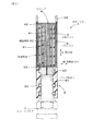
本例の点火コイル1は、図1〜図3に示すごとく、同心円状に巻回した1次コイル2及び2次コイル3と、スパークプラグ7を取り付けるプラグ取付口61とを備え、エンジンケースにおけるプラグホール内に挿入配置するよう構成されている。
Embodiments of the ignition coil and the manufacturing method thereof according to the present invention will be described below with reference to the drawings.
Example 1
As shown in FIGS. 1 to 3, the ignition coil 1 of this example includes a
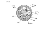
この点火コイル1は、図2、図3に示すごとく、1次コイル2及び2次コイル3の内周側に、金属製の中心コア4を備えると共に、1次コイル2及び2次コイル3の外周側に、金属製の外周筒5を備えている。そして、中心コア4は、複数の平板状の積層鋼板43を接着層44を介して点火コイル1の軸方向Lに直交するいずれかの径方向である横断面方向Wに向けて積層してなる。また、外周筒5は、複数の平板状の積層鋼板53を接着層54を介して点火コイル1の軸方向Lに直交するいずれかの径方向である横断面方向Wに向けて積層してなる。
以下に、これを詳説する。
As shown in FIGS. 2 and 3, the ignition coil 1 includes a metal
This will be described in detail below.
図1〜図3に示すごとく、上記1次コイル2は、円筒状樹脂からなる1次スプール21の外周面に絶縁被覆した1次ワイヤ22を巻回してなり、上記2次コイル3は、円筒状樹脂からなる2次スプール31の外周面に1次ワイヤ22よりも多い巻回数で絶縁被覆した2次ワイヤ32を巻回してなる。また、2次コイル3は、1次コイル2の内周側に挿通されており、2次コイル3の内周側に上記中心コア4が挿通されている。また、1次コイル2は、上記外周筒5の内周側に挿通されている。そして、1次コイル2に電流を流して発生させる磁束は、中心コア4及び外周筒5を通過させて増大させることができる。
なお、1次コイル2を2次コイル3の内周側に挿通してもよい。
As shown in FIGS. 1 to 3, the
The
図1に示すごとく、本例の点火コイル1は、1次コイル2に電力を供給するスイッチング素子等を有するイグナイタ部を備えていないものである。そして、点火コイル1の軸方向一端部(外周筒5の軸方向一端部501)には、1次コイル2の両端部に接続された一対の端子部33が配設されている。
また、点火コイル1の軸方向他端部(外周筒5の軸方向他端部502)には、上記プラグ取付口61を形成したプラグ取付筒6が配設されている。このプラグ取付筒6内には、プラグ取付口61に取り付けたスパークプラグ7の頭部と接触する導電部材62と、スパークプラグ7の外周面と密着するOリング63とが配設されている。また、上記導電部材62は、導電ゴムからなる。
また、2次コイル3の高圧側端部は、導電部材62に電気的に接続されており、2次コイル3の低圧側端部は、スパークプラグ7を介してエンジンケースに電気的に接続される。
As shown in FIG. 1, the ignition coil 1 of the present example does not include an igniter section having a switching element or the like that supplies power to the
In addition, a plug mounting cylinder 6 in which the
The high voltage side end of the
図2に示すごとく、本例においては、中心コア4の軸方向端部と外周筒5の軸方向端部とは、上記軸方向Lの両端部において連結されている。
すなわち、本例の中心コア4は、円形断面形状のコア本体部41と、このコア本体部41の軸方向一端部401から径方向外方に向けて突出したフランジ部42とを有している。また、本例では、コア本体部41に、磁束形成時の磁気的飽和を防止するためのギャップ35を形成している。このギャップ35は、中心コア4を軸方向Lに分割して形成した隙間に絶縁性のギャップ形成部材351を配置して形成されている。
また、本例の外周筒5は、円環断面形状の筒本体部51と、この筒本体部51の軸方向他端部502に形成された底部52とを有している。
As shown in FIG. 2, in this example, the axial end portion of the
That is, the
Further, the outer
そして、中心コア4のフランジ部42における外周面と、外周筒5の軸方向一端部501における内周面とが当接しており、中心コア4のコア本体部41における軸方向他端面402と、外周筒5の底部52における内側面とが当接している。こうして、中心コア4と外周筒5とは、1次コイル2に電流を流した際に生じる磁束を、ギャップ形成部材351を介して、中心コア4と外周筒5とへ連続して通過させることができる。また、上記ギャップ35を形成したことにより、上記磁束によって中心コア4及び外周筒5を磁気的に飽和させないようにすることができる。
And the outer peripheral surface in the
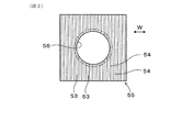
また、図5〜図8に示すごとく、本例の外周筒5は、複数の積層鋼板53を接着層54を介して積層してなる外周筒用積層体55から、円環断面形状に切り出してなる。そして、外周筒5の筒本体部51における外周面及び内周面は、互いに隣接する積層鋼板53による段差のない滑らかな曲面に形成されている。
また、図9〜図12に示すごとく、本例の中心コア4は、複数の積層鋼板43を接着層44を介して積層してなる中心コア用積層体45から、円形断面形状に切り出してなる。そして、中心コア4のコア本体部41及びフランジ部42における各外周面は、互いに隣接する積層鋼板43による段差のない滑らかな曲面に形成されている。
Moreover, as shown in FIGS. 5-8, the
Moreover, as shown in FIGS. 9-12, the
また、本例の点火コイル1は、高出力化を図ったことにより、軸方向長さを短く、外径を小さく形成したものである。
すなわち、上記外周筒5は、φ14〜17mmの外径を有し、30〜35mmの軸方向長さを有し、かつ0.46〜1.00mmの厚みを有している。また、上記中心コア4は、φ5〜8mmの外径を有している。
なお、外周筒5の加工性を向上させるために、中心コア4の外径をφ8mm以下としたときには、外周筒5の厚みは1mm以上にすることができる。
Moreover, the ignition coil 1 of this example is formed by shortening the axial length and reducing the outer diameter by increasing the output.
That is, the outer
In addition, in order to improve the workability of the outer
また、図2に示すごとく、本例では、上記1次コイル2に電流を流したときに生じる磁束の通過を容易にするために、上記中心コア4のコア本体部41がフランジ部42と繋がる部分の外周面には、コア本体部41の外径を緩やかに拡大させた曲線状角部(R形状部)411を設けている。また、このR形状部411の代わりにC面部を設けることもできる。また、R形状部411の大きさは、R0.2〜0.5mmの範囲にすることが好ましく、C面部の大きさは、C0.2〜0.5mmの範囲にすることが好ましい。
As shown in FIG. 2, in this example, the
また、上記磁束の通過を容易にするために、上記外周筒5の筒本体部51が底部52と繋がる部分の内周面には、筒本体部51の内径を緩やかに縮小させた曲線状角部(R形状部)511を設けている。また、このR形状部511の代わりにC面部を設けることもできる。また、R形状部511の大きさは、R0.2〜0.5mmの範囲にすることが好ましく、C面部の大きさは、C0.2〜0.5mmの範囲にすることが好ましい。
Further, in order to facilitate the passage of the magnetic flux, a curved corner in which the inner diameter of the
また、図示は省略するが、上記外周筒5の筒本体部51が底部52と繋がる部分の外周面にも、筒本体部51の外径を緩やかに縮小させた曲線状角部(R形状部)を設けてもよい。また、このR形状部の代わりにC面部を設けることもできる。
また、この外周面のR形状部又はC面部の大きさは、上記内周面のR形状部511又はC面部の大きさに、筒本体部51又は底部52の厚み分を加えた程度が好ましい。
このように、R形状部又はC面部を内周面及び外周面ともに設けることにより、磁束の通過が容易になると共に、外周筒5を小型化又は軽量化することができる。
Although not shown, a curved corner portion (R-shaped portion) in which the outer diameter of the cylinder
The size of the R-shaped portion or C-surface portion of the outer peripheral surface is preferably such that the thickness of the cylindrical
As described above, by providing the R-shaped portion or the C-surface portion together with the inner peripheral surface and the outer peripheral surface, the magnetic flux can be easily passed, and the outer
次に、上記点火コイル1を製造する方法につき、図4〜図12と共に説明する。
本例の点火コイル1の製造方法においては、以下の外周筒用積層工程及び外周筒切出工程を行って外周筒5を作製し、以下の中心コア用積層工程及び中心コア切出工程を行って中心コア4を作製する。
Next, a method for manufacturing the ignition coil 1 will be described with reference to FIGS.
In the manufacturing method of the ignition coil 1 of this example, the
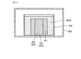
上記外周筒5を作製するに当たっては、まず、外周筒用積層工程として、複数の平板状の積層鋼板53を接着層54を介して一方向に積層して、外周筒用積層体55を得る。
図4に示すごとく、この外周筒用積層工程においては、真空含浸接着法を用いて複数の平板状の積層鋼板53を接着する。すなわち、本工程においては、重ね合わせて保持した状態の複数の積層鋼板53を、接着剤800の溶液中に含浸させ、真空状態と大気圧状態とを形成することにより、積層鋼板53同士の間の隙間に、接着剤800を浸透させる。その後、接着剤800を乾燥させて、複数の積層鋼板53同士を接着させることにより、外周筒用積層体55を得る。
In producing the outer
As shown in FIG. 4, in this outer cylinder stacking step, a plurality of flat
より具体的には、図4に示すごとく、まず、複数の積層鋼板53を重ね合わせた状態で、保持治具81内に保持する。次いで、この保持治具81を含浸容器82内に配置すると共に含浸容器82内に接着剤800の溶液を注入し、保持治具81における複数の積層鋼板53を接着剤800の溶液中に含浸させる。
次いで、複数の積層鋼板53を接着剤800の溶液中に含浸した状態の含浸容器82を真空タンク83内に配置し、真空タンク83内を真空状態(20mmHg以下)にして所定時間(10分程度)放置する。次いで、真空タンク83内を大気圧状態に戻し、複数の積層鋼板53を接着剤800の溶液中に含浸させたまま所定時間(5分程度)放置する。これにより、積層鋼板53同士の間の隙間に接着剤800を容易に浸透させることができる。
More specifically, as shown in FIG. 4, first, a plurality of
Next, the
そして、保持治具81の表面の接着剤800を拭き取った後、保持治具81を加熱(約120℃で60分程度)し、積層鋼板53同士の間の隙間に浸透した接着剤800を乾燥させて、上記外周筒用積層体55を得る。そして、各積層鋼板53同士の間には、接着剤800が充填されて、接着層54が形成される。
Then, after the adhesive 800 on the surface of the holding
次いで、図5〜図8に示すごとく、外周筒切出工程として、上記外周筒用積層体55における複数の積層鋼板53の積層方向Wが上記外周筒5の軸方向Lに直交する方向に向くよう当該外周筒用積層体55を外周筒5の外形に沿って切り出す。
この外周筒切出工程においては、切出加工としての放電加工及びワイヤ放電加工を行って、上記外周筒用積層体55を切り出す。
Next, as shown in FIGS. 5 to 8, as the outer peripheral cylinder cutting step, the stacking direction W of the plurality of
In this outer peripheral cylinder cutting step, electric discharge machining and wire electric discharge machining are performed as the cutting process, and the outer
すなわち、図5、図6に示すごとく、本工程においては、外周筒用積層体55に積層方向Wに直交する方向から放電加工を行い、外周筒5の内周面の形状を有する凹状穴56を明ける。次いで、図7、図8に示すごとく、外周筒用積層体55における凹状穴56の周りにワイヤ放電加工を行い、当該外周筒用積層体55を外周筒5の外周面の形状を有する円筒状に切り出す。このとき、円筒状の外周筒用積層体55は、上記筒本体部51と上記底部52とを有する有底円筒形状に形成される。その後、上記底部52を、ワイヤ放電加工を行って所定の厚みに加工する。
こうして、複数の平板状の積層鋼板53を、接着層54を介して軸方向Lに直交する横断面方向Wに積層してなる外周筒5を作製することができる。
That is, as shown in FIG. 5 and FIG. 6, in this step, the
In this way, it is possible to produce the outer
また、上記中心コア4を作製するに当たっては、まず、中心コア用積層工程として、複数の平板状の積層鋼板43を接着層44を介して一方向に積層して、中心コア用積層体45を得る。
図4に示すごとく、中心コア用積層工程においては、真空含浸接着法を用いて複数の平板状の積層鋼板43を接着する。すなわち、本工程においては、重ね合わせて保持した状態の複数の積層鋼板43を、接着剤800の溶液中に含浸させ、真空状態と大気圧状態とを形成することにより、積層鋼板43同士の間の隙間に、接着剤800を浸透させる。その後、接着剤800を乾燥させて、複数の積層鋼板43同士を接着させることにより、中心コア用積層体45を得る。
その他、中心コア用積層工程においても、上記外周筒用積層工程と同様の作業を行うことによって中心コア用積層体45を得ることができる。
In producing the
As shown in FIG. 4, in the central core laminating step, a plurality of flat
In addition, in the central core laminating process, the central core laminated
次いで、図9〜図12に示すごとく、中心コア切出工程として、上記中心コア用積層体45における複数の積層鋼板43の積層方向Wが上記中心コア4の軸方向Lに直交する方向に向くよう当該中心コア用積層体45を中心コア4の外形に沿って切り出す。
この中心コア切出工程においては、切出加工としての放電加工及びワイヤ放電加工を行って、上記中心コア用積層体45を切り出す。
Next, as shown in FIGS. 9 to 12, as the center core cutting process, the stacking direction W of the plurality of
In the center core cutting step, the
すなわち、図9、図10に示すごとく、本工程においては、中心コア用積層体45に積層方向Wに直交する方向から放電加工を行い、中心コア4の外周面の形状を内周側に有する環状の凹状穴46を明ける。次いで、図11、図12に示すごとく、中心コア用積層体45における環状の凹状穴46の外周縁部に沿ってワイヤ放電加工を行い、当該中心コア用積層体45を円柱状に切り出す。このとき、円柱状の中心コア用積層体45は、上記コア本体部41と上記フランジ部42とを有する段付円柱形状に形成される。その後、上記フランジ部42を、ワイヤ放電加工を行って所定の厚みに加工する。
こうして、複数の平板状の積層鋼板43を、接着層44を介して軸方向Lに直交する横断面方向Wに積層してなる中心コア4を作製することができる。
That is, as shown in FIGS. 9 and 10, in this step, the
Thus, the
上記のように作製してなる中心コア4及び外周筒5を有する点火コイル1は、以下の理由で高出力化及び小型化を図ることができる。
すなわち、上記中心コア4及び外周筒5は、それぞれ複数の積層鋼板43、53を、点火コイル1の軸方向Lに直交する横断面方向Wに向けて積層してなる。
そして、上記点火コイル1を使用する際に、エンジンのECU(電子制御ユニット)等から1次コイル2に電力が供給されると、この1次コイル2を流れる電流により生ずる磁束は、中心コア4及び外周筒5を通過する。このとき、中心コア4及び外周筒5における各積層鋼板43、53の1つ1つが上記磁束を通過させる磁路を形成し、上記磁束は、複数の積層鋼板43、53をそれぞれ通過することができる。
The ignition coil 1 having the
That is, the
When electric power is supplied to the
一方、中心コア4及び外周筒5における各積層鋼板43、53は、各接着層44、54を介して上記横断面方向Wに細かく分断されており、横断面方向Wに向けて並ぶ各接着層44、54によって、磁束形成による渦電流の発生を効果的に抑制することができる。これにより、上記磁束によって誘導されて上記2次コイル3に生ずる誘導起電力(逆起電力)を容易に大きくすることができる。そのため、上記点火コイル1のプラグ取付口61に取り付けたスパークプラグ7から発生させるスパークを容易に大きくすることができ、点火コイル1の高出力化を図ることができる。
また、点火コイル1の高出力化を実現することにより、点火コイル1の出力を小さくすることなく、点火コイル1の軸方向長さ又は外径の小型化を図ることができる。
On the other hand, the
Further, by realizing high output of the ignition coil 1, it is possible to reduce the axial length or the outer diameter of the ignition coil 1 without reducing the output of the ignition coil 1.
そして、点火コイル1の軸方向長さを短くすることにより、エンジンルームにおける限られたスペースにおいても、周辺との干渉を回避して点火コイル1をエンジンケースに搭載することが可能になる。また、点火コイル1の軸方向長さを短くすることにより、エンジンの低重心化を図ることができ、車両の走行性能を向上させることもできる。
また、点火コイル1の外径を小さくすることにより、エンジンケースにおける冷却手段の配置スペースを大きくすることが可能になる。
And by shortening the axial direction length of the ignition coil 1, it becomes possible to avoid the interference with the periphery and to mount the ignition coil 1 in the engine case even in a limited space in the engine room. Further, by shortening the length of the ignition coil 1 in the axial direction, the center of gravity of the engine can be lowered, and the running performance of the vehicle can be improved.
Further, by reducing the outer diameter of the ignition coil 1, it is possible to increase the arrangement space of the cooling means in the engine case.
さらに、上記中心コア4は、上記中心コア用積層体45から円形断面形状に切り出してなり、上記外周筒5は、上記外周筒用積層体55から円環断面形状に切り出してなる。
そのため、中心コア4における外周面と、外周筒5における外周面及び内周面とは、互いに隣接する積層鋼板43、53による段差のない滑らかな曲面に形成されている。そのため、中心コア4及び外周筒5において段差の形成による無駄なスペースがなく、直径が小さな中心コア4を作製することができると共に、径方向厚みが小さな外周筒5を作製することができる。
それ故、一層小型化を図った点火コイル1を製造することができる。
Further, the
Therefore, the outer peripheral surface of the
Therefore, the ignition coil 1 that is further miniaturized can be manufactured.
(実施例2)
本例は、図13〜図16に示すごとく、上記中心コア4及び上記外周筒5の加工性を向上させるために、これらを構成する複数の積層鋼板43、53の厚みを部分的に異ならせる工夫を行った例である。
すなわち、本例においては、図13に示すごとく、上記外周筒5を作製するに際し、上記外周筒用積層工程においては、一般部積層鋼板551と、この一般部積層鋼板551よりも厚い特別部積層鋼板552とを用いて上記外周筒用積層体55を形成する。
(Example 2)
In this example, as shown in FIGS. 13 to 16, in order to improve the workability of the
That is, in this example, as shown in FIG. 13, when producing the outer
そして、図13、図14に示すごとく、外周筒用積層体55において、外周筒5における上記横断面方向(積層方向)Wの最も外側に位置させる2つの外側積層鋼板53Aに相当する位置にある積層鋼板53を、特別部積層鋼板552にする。また、外周筒5における内周面を形成する積層鋼板53のうち上記横断面方向Wの最も外側に位置させる2つの内周面外側積層鋼板53Bに相当する位置にある積層鋼板53を、特別部積層鋼板552にする。
また、外側積層鋼板53A及び内周面外側積層鋼板53B以外の一般部に相当する位置にある多数の積層鋼板53は、一般部積層鋼板551とする。
As shown in FIGS. 13 and 14, in the
A large number of
次いで、上記外周筒切出工程において、上記外周筒用積層体55から上記外周筒5の外形を切り出す際には、上記外側積層鋼板53Aに相当する位置にある2つの積層鋼板53と、内周面外側積層鋼板53Bに相当する位置にある2つの積層鋼板53とには、円形状の加工ラインTがそれらの積層鋼板53の面方向Dに近い方向に向けて描かれる。そして、加工ラインTに沿って外周筒用積層体55を切り出して外周筒5を形成する。
Next, in the outer peripheral cylinder cutting step, when cutting the outer shape of the outer
そこで、面方向Dに近い方向に向けて分断する必要が生じる各積層鋼板53を、他の一般部積層鋼板551に比べて厚い特別部積層鋼板552とすることにより、上記外周筒用積層体55から外周筒5を切り出す際に、形崩れが生ずることを抑制することができる。これにより、上記外周筒用積層体55の切出加工性を向上させることができ、外側積層鋼板53A及び内周面外側積層鋼板53Bにおいても形崩れのほとんどない外周筒5を容易に形成することができる。
Therefore, the outer
また、本例においては、図15に示すごとく、上記中心コア4を作製するに際し、上記中心コア用積層工程においては、一般部積層鋼板451と、この一般部積層鋼板451よりも厚い特別部積層鋼板452とを用いて上記中心コア用積層体45を形成する。
そして、図15、図16に示すごとく、中心コア用積層体45において、中心コア4における上記横断面方向(積層方向)Wの最も外側に位置させる2つの外側積層鋼板43Aに相当する位置にある積層鋼板43を、特別部積層鋼板452にする。また、外側積層鋼板43A以外の一般部に相当する位置にある多数の積層鋼板43は、一般部積層鋼板451とする。
Further, in this example, as shown in FIG. 15, when the
As shown in FIGS. 15 and 16, the central core laminated
次いで、上記中心コア切出工程において、上記中心コア用積層体45から上記中心コア4の外形を切り出す際には、上記外側積層鋼板43Aに相当する位置にある2つの積層鋼板43には、円形状の加工ラインTがそれらの積層鋼板43の面方向Dに近い方向に向けて描かれる。そして、加工ラインTに沿って中心コア用積層体45を切り出して中心コア4を形成する。
Next, when the outer shape of the
そこで、面方向Dに近い方向に向けて分断する必要が生じる2つの積層鋼板43を、他の一般部積層鋼板451に比べて厚い特別部積層鋼板452とすることにより、上記中心コア用積層体45から中心コア4を切り出す際に、形崩れが生ずることを抑制することができる。これにより、上記中心コア用積層体45の切出加工性を向上させることができ、外側積層鋼板43Aにおいても形崩れのほとんどない中心コア4を容易に形成することができる。
本例においても、その他は上記実施例1と同様であり、上記実施例1と同様の作用効果を得ることができる。
Accordingly, the two
Also in this example, the other parts are the same as those in the first embodiment, and the same effects as those in the first embodiment can be obtained.
1 点火コイル
2 1次コイル
3 2次コイル
4 中心コア
41 コア本体部
42 フランジ部
43 積層鋼板
43A 外側積層鋼板
44 接着層
45 中心コア用積層体
451 一般部積層鋼板
452 特別部積層鋼板
5 外周筒
51 筒本体部
52 底部
53 積層鋼板
53A 外側積層鋼板
53B 内周面外側積層鋼板
54 接着層
55 外周筒用積層体
551 一般部積層鋼板
552 特別部積層鋼板
6 プラグ取付筒
61 プラグ取付口
7 スパークプラグ
L 軸方向
W 横断面方向
DESCRIPTION OF SYMBOLS 1
Claims (7)
該点火コイルは、上記1次コイル及び2次コイルの内周側に、金属製の中心コアを備えると共に、上記1次コイル及び2次コイルの外周側に、金属製の外周筒を備えており、該外周筒及び上記中心コアは、複数の積層鋼板を接着層を介して上記点火コイルの軸方向に直交する横断面方向に向けて積層してなり、
上記中心コアの軸方向端部と上記外周筒の軸方向端部とは、上記軸方向の両端部の全周において連結されており、
上記中心コアは、切出加工を行うことによって、円形断面形状のコア本体部と、該コア本体部の軸方向一端部から径方向外方に向けて突出したフランジ部とを一体的に有しており、該フランジ部及び上記コア本体部における各外周面は、互いに隣接する上記積層鋼板による段差のない滑らかな曲面に形成されており、
上記外周筒は、切出加工を行うことによって、円環断面形状の筒本体部と、該筒本体部の軸方向他端部に形成された底部とを一体的に有しており、上記筒本体部における外周面及び内周面は、互いに隣接する上記積層鋼板による段差のない滑らかな曲面に形成されていることを特徴とする点火コイル。 An ignition coil comprising a primary coil and a secondary coil concentrically wound, and a plug mounting opening for attaching a spark plug, and configured to be inserted into a plug hole in an engine case,
The ignition coil includes a metal central core on the inner peripheral side of the primary coil and the secondary coil, and a metal outer cylinder on the outer peripheral side of the primary coil and the secondary coil. The outer peripheral cylinder and the central core are formed by laminating a plurality of laminated steel sheets in a cross-sectional direction orthogonal to the axial direction of the ignition coil via an adhesive layer,
The axial end portion of the central core and the axial end portion of the outer peripheral cylinder are connected at the entire circumference of both end portions in the axial direction ,
The center core integrally includes a core body portion having a circular cross-sectional shape and a flange portion projecting radially outward from one axial end portion of the core body portion by performing a cutting process. And each outer peripheral surface of the flange portion and the core main body portion is formed into a smooth curved surface without a step due to the laminated steel plates adjacent to each other,
The outer peripheral cylinder integrally includes a cylindrical main body having an annular cross-sectional shape and a bottom formed at the other axial end of the cylindrical main body by cutting. An ignition coil characterized in that an outer peripheral surface and an inner peripheral surface of the main body are formed as smooth curved surfaces having no step due to the laminated steel plates adjacent to each other .
上記筒本体部が上記底部と繋がる部分の内周面には、上記筒本体部の内径を緩やかに縮小させた曲線状角部(R形状部)が設けられていることを特徴とする点火コイル。 An ignition coil characterized in that a curved corner portion (R-shaped portion) in which an inner diameter of the cylindrical body portion is gradually reduced is provided on an inner peripheral surface of a portion where the cylindrical body portion is connected to the bottom portion. .
Priority Applications (1)
| Application Number | Priority Date | Filing Date | Title |
|---|---|---|---|
| JP2004366107A JP4635598B2 (en) | 2004-12-17 | 2004-12-17 | Ignition coil |
Applications Claiming Priority (1)
| Application Number | Priority Date | Filing Date | Title |
|---|---|---|---|
| JP2004366107A JP4635598B2 (en) | 2004-12-17 | 2004-12-17 | Ignition coil |
Publications (2)
| Publication Number | Publication Date |
|---|---|
| JP2006173466A JP2006173466A (en) | 2006-06-29 |
| JP4635598B2 true JP4635598B2 (en) | 2011-02-23 |
Family
ID=36673863
Family Applications (1)
| Application Number | Title | Priority Date | Filing Date |
|---|---|---|---|
| JP2004366107A Expired - Fee Related JP4635598B2 (en) | 2004-12-17 | 2004-12-17 | Ignition coil |
Country Status (1)
| Country | Link |
|---|---|
| JP (1) | JP4635598B2 (en) |
Families Citing this family (2)
| Publication number | Priority date | Publication date | Assignee | Title |
|---|---|---|---|---|
| US8786392B2 (en) * | 2011-02-22 | 2014-07-22 | Federal-Mogul Ignition Company | Corona igniter with improved energy efficiency |
| SE541409C2 (en) | 2017-06-19 | 2019-09-24 | Sem Ab | Spark plug extension |
Family Cites Families (8)
| Publication number | Priority date | Publication date | Assignee | Title |
|---|---|---|---|---|
| JP2653160B2 (en) * | 1989-03-13 | 1997-09-10 | 株式会社デンソー | solenoid valve |
| JP2995763B2 (en) * | 1989-11-10 | 1999-12-27 | 株式会社デンソー | Ignition coil |
| JPH097860A (en) * | 1995-06-21 | 1997-01-10 | Hitachi Ltd | Ignition coil for internal combustion engine |
| JPH104019A (en) * | 1996-06-14 | 1998-01-06 | Toyota Motor Corp | Ignition coil for internal combustion engine |
| JPH10303047A (en) * | 1997-04-30 | 1998-11-13 | Denso Corp | Ignition coil for internal combustion engine |
| US6049264A (en) * | 1997-12-09 | 2000-04-11 | Siemens Automotive Corporation | Electromagnetic actuator with composite core assembly |
| US6162311A (en) * | 1998-10-29 | 2000-12-19 | Mmg Of North America, Inc. | Composite magnetic ceramic toroids |
| JP4032292B2 (en) * | 2002-05-13 | 2008-01-16 | 株式会社デンソー | Manufacturing method of integrated core for coil |
-
2004
- 2004-12-17 JP JP2004366107A patent/JP4635598B2/en not_active Expired - Fee Related
Also Published As
| Publication number | Publication date |
|---|---|
| JP2006173466A (en) | 2006-06-29 |
Similar Documents
| Publication | Publication Date | Title |
|---|---|---|
| CN103026435B (en) | Reactor device | |
| JPH09186029A (en) | Ignition coil for internal combustion engine | |
| JP5087880B2 (en) | Reactor | |
| JP7452616B2 (en) | Ignition coil for internal combustion engine | |
| JP4635598B2 (en) | Ignition coil | |
| JP2006278867A (en) | Ignition coil for internal combustion engine | |
| JPH11265833A (en) | Core for ignition coil and its manufacture | |
| JP2014212222A (en) | Ignition coil for internal combustion engine | |
| JP3671171B2 (en) | Coil device and manufacturing method thereof | |
| JP2006303447A (en) | Ignition coil | |
| US20200381177A1 (en) | Ignition coil device | |
| JP2000324740A (en) | Motor stator | |
| JP2007053188A (en) | Ignition coil for internal combustion engine | |
| JP2008199719A (en) | Rotating electric machine and field coil manufacturing method | |
| JP2002231543A (en) | Ignition coil for internal combustion engine | |
| JP2005236263A (en) | Ignition coil and its manufacturing method | |
| JP2008053676A (en) | Ignition coil and manufacturing method thereof | |
| JP5776338B2 (en) | Ignition coil | |
| JP2002136020A (en) | Iron core of stator coated with resin-made insulating layer for generator for internal combustion engine | |
| JP2006165150A (en) | Ignition coil for internal combustion engine | |
| JP2000323338A (en) | Ignition coil for internal combustion engine | |
| JP3802008B2 (en) | Ignition coil for internal combustion engine | |
| KR100783413B1 (en) | Stator stacking structure of reciprocating motor | |
| JPH08186958A (en) | Stator laminated iron core and manufacturing method thereof | |
| JP2017126590A (en) | Transformer component cross-section structure and ignition coil including the same. |
Legal Events
| Date | Code | Title | Description |
|---|---|---|---|
| A621 | Written request for application examination |
Free format text: JAPANESE INTERMEDIATE CODE: A621 Effective date: 20070123 |
|
| A977 | Report on retrieval |
Free format text: JAPANESE INTERMEDIATE CODE: A971007 Effective date: 20090806 |
|
| A131 | Notification of reasons for refusal |
Free format text: JAPANESE INTERMEDIATE CODE: A131 Effective date: 20090818 |
|
| A521 | Request for written amendment filed |
Free format text: JAPANESE INTERMEDIATE CODE: A523 Effective date: 20091015 |
|
| A131 | Notification of reasons for refusal |
Free format text: JAPANESE INTERMEDIATE CODE: A131 Effective date: 20100817 |
|
| A521 | Request for written amendment filed |
Free format text: JAPANESE INTERMEDIATE CODE: A523 Effective date: 20101007 |
|
| TRDD | Decision of grant or rejection written | ||
| A01 | Written decision to grant a patent or to grant a registration (utility model) |
Free format text: JAPANESE INTERMEDIATE CODE: A01 Effective date: 20101026 |
|
| A01 | Written decision to grant a patent or to grant a registration (utility model) |
Free format text: JAPANESE INTERMEDIATE CODE: A01 |
|
| A61 | First payment of annual fees (during grant procedure) |
Free format text: JAPANESE INTERMEDIATE CODE: A61 Effective date: 20101108 |
|
| FPAY | Renewal fee payment (event date is renewal date of database) |
Free format text: PAYMENT UNTIL: 20131203 Year of fee payment: 3 |
|
| R151 | Written notification of patent or utility model registration |
Ref document number: 4635598 Country of ref document: JP Free format text: JAPANESE INTERMEDIATE CODE: R151 |
|
| FPAY | Renewal fee payment (event date is renewal date of database) |
Free format text: PAYMENT UNTIL: 20131203 Year of fee payment: 3 |
|
| R250 | Receipt of annual fees |
Free format text: JAPANESE INTERMEDIATE CODE: R250 |
|
| R250 | Receipt of annual fees |
Free format text: JAPANESE INTERMEDIATE CODE: R250 |
|
| R250 | Receipt of annual fees |
Free format text: JAPANESE INTERMEDIATE CODE: R250 |
|
| R250 | Receipt of annual fees |
Free format text: JAPANESE INTERMEDIATE CODE: R250 |
|
| R250 | Receipt of annual fees |
Free format text: JAPANESE INTERMEDIATE CODE: R250 |
|
| R250 | Receipt of annual fees |
Free format text: JAPANESE INTERMEDIATE CODE: R250 |
|
| R250 | Receipt of annual fees |
Free format text: JAPANESE INTERMEDIATE CODE: R250 |
|
| LAPS | Cancellation because of no payment of annual fees |