JP4635581B2 - Optical scanning device - Google Patents
Optical scanning device Download PDFInfo
- Publication number
- JP4635581B2 JP4635581B2 JP2004342603A JP2004342603A JP4635581B2 JP 4635581 B2 JP4635581 B2 JP 4635581B2 JP 2004342603 A JP2004342603 A JP 2004342603A JP 2004342603 A JP2004342603 A JP 2004342603A JP 4635581 B2 JP4635581 B2 JP 4635581B2
- Authority
- JP
- Japan
- Prior art keywords
- mirror
- reflecting mirror
- reinforcing member
- scanning device
- optical scanning
- Prior art date
- Legal status (The legal status is an assumption and is not a legal conclusion. Google has not performed a legal analysis and makes no representation as to the accuracy of the status listed.)
- Expired - Fee Related
Links
Images


Landscapes
- Mechanical Optical Scanning Systems (AREA)
Description
本発明は、光走査装置にかかり、特に、画像形成装置に用いた際に高解像度の画像を形成可能とする光走査装置に関する。 The present invention relates to an optical scanning device, and more particularly to an optical scanning device capable of forming a high-resolution image when used in an image forming apparatus.
近年、市場では高解像度の画像形成装置が要求されており、画質低下の原因の一つとなっている光走査装置の反射鏡の振動を低減することが不可欠になってきている。 In recent years, a high-resolution image forming apparatus is required in the market, and it is indispensable to reduce the vibration of the reflecting mirror of the optical scanning apparatus, which is one of the causes of image quality degradation.
従来より、振動の低減を目的として反射鏡の剛性を上げる技術は知られており、例えば、特許文献1においては、反射鏡の側面に補強部材を設ける技術が開示されている。
近年では、光走査装置を複数の仕様が異なる画像形成装置に提供する場合がある。 In recent years, there are cases where an optical scanning device is provided to a plurality of image forming apparatuses having different specifications.
そのため、反射鏡の剛性を上げても、振動源の振動周波数が画像形成装置毎に多数存在するため、共振周波数を避けることが困難であり、共振により反射鏡が大きく振動してしまう場合がある。 For this reason, even if the rigidity of the reflecting mirror is increased, it is difficult to avoid the resonance frequency because there are many vibration frequencies of the vibration source for each image forming apparatus, and the reflection mirror may vibrate greatly due to resonance. .
また、反射鏡は、振動による反射鏡の撓みによるビームの位置変動の他に、補強によって反射鏡の剛性を上げることで反射鏡の重量バランスが悪くなり、走査線方向を軸として反射鏡が回転運動してビームの位置変動を起こす場合もある。 In addition to the beam position fluctuation caused by the deflection of the reflecting mirror due to vibration, the reflecting mirror's weight balance is worsened by increasing the rigidity of the reflecting mirror through reinforcement, and the reflecting mirror rotates around the scanning line direction. It may move and cause beam position fluctuations.
その結果、バンディングが発生して近年の高画質の要求を満足するには不十分な場合があった。 As a result, banding has occurred, which is insufficient to satisfy the recent demand for high image quality.
本発明は、上記問題を解決すべく成されたもので、画像形成装置に用いた際に高品質の画像を得ることができる光走査装置の提供を目的とする。 The present invention has been made to solve the above problem, and an object of the present invention is to provide an optical scanning device capable of obtaining a high-quality image when used in an image forming apparatus.
請求項1に記載の発明は、光ビームを出射する光源と、出射された光ビームを主走査方向に偏向させる偏向手段と、偏向された光ビームを被走査面上に結像させる光学系と、前記偏向手段と被走査面との間に設けられて光ビームを反射する反射鏡と、を備え、前記反射鏡は、装置本体のフレームに取り付けられ、前記反射鏡には、補強部材が複数箇所で点状に固定されていると共に、前記補強部材は、前記反射鏡の端面に固定される側部と、前記側部に連結され、前記反射鏡及び前記装置本体のフレームと離間して配置される振動部とを有し、前記振動部は、振動入力時に前記反射鏡の振動を抑えるように振動する、ことを特徴としている。 According to a first aspect of the present invention, there is provided a light source that emits a light beam, deflection means that deflects the emitted light beam in the main scanning direction, and an optical system that forms an image of the deflected light beam on a surface to be scanned. A reflecting mirror provided between the deflecting means and the surface to be scanned to reflect the light beam, and the reflecting mirror is attached to a frame of the apparatus body, and the reflecting mirror includes a plurality of reinforcing members. The reinforcing member is fixed in a spot shape at a location, and the reinforcing member is connected to the side portion fixed to the end face of the reflecting mirror, and is connected to the side portion and spaced apart from the reflecting mirror and the frame of the apparatus main body. The vibration part vibrates so as to suppress the vibration of the reflecting mirror at the time of vibration input.
次に、請求項1に記載の光走査装置の作用を説明する。 Next, the operation of the optical scanning device according to claim 1 will be described .
請求項1に記載の光走査装置では、反射面の両側部に補強部材が複数箇所で点状に固定されているため、反射鏡の剛性を上げることができ、反射鏡自体の変形による振動を抑えることができる。 In the optical scanning device according to claim 1, since the reinforcing members are fixed to the both sides of the reflecting surface in a dot shape at a plurality of locations, the rigidity of the reflecting mirror can be increased, and vibration due to deformation of the reflecting mirror itself is generated. Can be suppressed.
さらに、補強部材は、反射鏡と離間して配置され振動入力時に振動する振動部を有するので、振動入力時に振動部が振動して、いわゆるダイナミックダンパとして作用するので反射鏡の振動を更に抑えることが出来る。 Furthermore, since the reinforcing member has a vibrating portion that is arranged away from the reflecting mirror and vibrates when a vibration is input, the vibrating portion vibrates when the vibration is input and acts as a so-called dynamic damper, thereby further suppressing the vibration of the reflecting mirror. I can do it.
請求項2に記載の発明は、請求項1に記載の光走査装置において、前記反射鏡の両側部で単一の前記補強部材が固定されている、ことを特徴としている。 According to a second aspect of the invention, in the optical scanning device according to claim 1, a single of the reinforcing member at both sides of the reflecting mirror is fixed, it is characterized in that.
次に、請求項2に記載の光走査装置の作用を説明する。 Next, the operation of the optical scanning device according to claim 2 will be described .
請求項2に記載の光走査装置では、反射鏡の両側部で単一の補強部材が固定されているため、反射鏡の走査線方向を軸とする回転方向のバランスをとることができ、反射鏡を該回転方向に振動させないようにできる。 In the optical scanning device according to claim 2 , since the single reinforcing member is fixed on both side portions of the reflecting mirror, it is possible to balance the rotation direction around the scanning line direction of the reflecting mirror, and to reflect The mirror can be prevented from vibrating in the direction of rotation.
請求項3に記載の発明は、請求項1または請求項2に記載の光走査装置において、前記補強部材は、前記反射鏡の少なくとも一方の側部において、弾性体を介して前記反射鏡に接触している、ことを特徴としている。 According to a third aspect of the present invention, in the optical scanning device according to the first or second aspect, the reinforcing member contacts the reflecting mirror via an elastic body on at least one side portion of the reflecting mirror. It is characterized by that.
次に、請求項3に記載の光走査装置の作用を説明する。
Next, the operation of the optical scanning device according to
補強部材を両側部で反射鏡に接触させて保持するが、一方の側部においては弾性体を介して反射鏡に接触させて保持する構成をとることで、反射鏡の剛性を向上させ、かつ振動部の振動が反射鏡に伝達し難くなり、反射鏡を更に振動させ難くできる。 The reinforcing member is held in contact with the reflecting mirror on both sides, but the rigidity of the reflecting mirror is improved by taking a configuration in which the reinforcing member is held in contact with the reflecting mirror via an elastic body on one side, and The vibration of the vibration part becomes difficult to be transmitted to the reflecting mirror, and the reflecting mirror can be further prevented from vibrating.
請求項4に記載の発明は、請求項1乃至請求項3の何れか1項に記載の光走査装置において、前記反射鏡と前記補強部材とは、前記反射鏡の両側部の互いに対向する位置にて固定されている、ことを特徴としている。 According to a fourth aspect of the present invention, in the optical scanning device according to any one of the first to third aspects, the reflecting mirror and the reinforcing member are positioned opposite to each other on both sides of the reflecting mirror. It is characterized by being fixed by.
次に、請求項4に記載の光走査装置の作用を説明する。 Next, the operation of the optical scanning device according to claim 4 will be described .
例えば、反射鏡と補強部材とを固定する場合、固定箇所の数や、固定位置が一方の側部と他方の側部とで異なる場合、例えば、反射鏡と補強部材の線膨張係数が異なり、かつそれぞれに温度変化が生じた場合に、反射鏡に作用する熱膨張に起因する力のバランスが一方の側と他方の側とで異なって反射鏡が歪む(湾曲)する虞がある。 For example, when fixing the reflecting mirror and the reinforcing member, if the number of fixing points and the fixing position are different between one side and the other side, for example, the linear expansion coefficient of the reflecting mirror and the reinforcing member is different, In addition, when a temperature change occurs in each, the balance of the force due to thermal expansion acting on the reflecting mirror may be different on one side and the other side, and the reflecting mirror may be distorted (curved).
しかしながら、反射鏡と強部材とを、反射鏡の両側部の互いに対向する位置にて固定する構成とすれば、両側部の保持条件が同一となり、反射鏡の剛性を向上させつつ、反射鏡の歪み(湾曲)を極力抑えることができる。 However, if the reflecting mirror and the strong member are fixed at opposite positions on both sides of the reflecting mirror, the holding conditions on both sides become the same, and the rigidity of the reflecting mirror is improved while improving the rigidity of the reflecting mirror. Distortion (curvature) can be suppressed as much as possible.
以上説明したように本発明によれば、画像形成装置に用いた際に高品質の画像を得ることが出来る、という優れた効果を有する。 As described above, according to the present invention, there is an excellent effect that a high-quality image can be obtained when used in an image forming apparatus.
[参考例]
本発明の実施形態を説明する前に、図面を参照して参考例に係る光走査装置10を図面に従って説明する。
(光走査装置の概略構成)
図1、及び図2は、本参考例に係る光走査装置10の概略構成図である。
[ Reference example ]
Before describing an embodiment of the present invention, an
(Schematic configuration of optical scanning device)
1 and 2 are schematic configuration diagrams of an
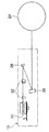
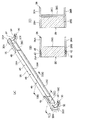
この光走査装置10は、レーザー光源12から出射された光ビームLが、コリメータレンズ14、スリット16、シリンドリカルレンズ18を通過し、回転多面鏡20により変更され、回転多面鏡20により偏向された光ビームLは、2枚のfθレンズ22を介して感光体24上を等速で走査するように主走査方向(矢印A方向)に走査される構成である。なお、fθレンズ22を通過した光ビームLは、ミラー26、及びミラー28で折り返されて感光体上24に結像される。
(ミラーの保持構造)
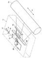
図3、及び図4に示すように、ミラー26は、光走査装置10のフレームに一体的に設けられた一対のブラケット30に保持されている。
In this
(Mirror holding structure)
As shown in FIGS. 3 and 4, the
ブラケット30は、フレームと一体的に設けられたベース部30Aと、該ベース部30Aと直角に設けられた支柱部30Bとを備えている。
The
本参考例のミラー26は、長尺状に形成され、その長手方向直角断面が長方形である。
The
ブラケット30のベース部30Aには、板ばね32が螺子34で固定されている。
A
ミラー26は、反射面を支柱部30B側に向けて配置されており、板ばね32は、ミラー32の反射面を支柱部30Bに押圧している。
The
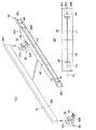
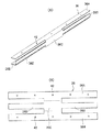
このミラー26には、補強部材36が取り付けられている。
A reinforcing
補強部材36の材質は特に問わないが、本参考例では金属を用いている。
The material of the reinforcing
補強部材36は、図4(B)に示すような長方形の金属板38に略H形状のスリット40、孔42、及び孔44をプレス等で打ち抜き後、2点鎖線で示す部分で折り曲げることで断面コ字形状に形成されている。
The reinforcing
図に示すように、補強部材36は、ミラー26の反射面の長手方向とは直交する方向の両側に位置する端面26A、26Bに対向して平行に設けられる部分が側部36A、36Bであり、側部36Aと側部36Bとを連結し、ミラー26の反射面とは反対側の裏面26Cと対向する部分が連結部36Cとされている。
As shown in the figure, the reinforcing
この補強部材36は、幅方向中心線CLを境にして対称形状であり、即ち、幅方向中心線CLを境にして図面上側部分の重量と図面下側部分との重量は同じに設定されている。
The reinforcing
補強部材36には、側部36A、36Bに複数の孔42が長手方向に沿って形成されており、連結部36Cの中央部分に孔44が形成されている。
In the reinforcing
なお、側部36A、及び側部36Bには、それぞれ5個の孔42が形成されており、かつ側部36Aの孔42と側部36Bの孔42とはそれぞれ対向する位置に形成されている。また、各孔42は、補強部材36の長手方向中心を対称軸として左右対称位置に形成されている。
Each of the
ここで、孔42、及び孔44にはそれぞれ合成樹脂系の接着剤46が流し込まれており、補強部材36は、ミラー26に対して接着剤部分にて複数箇所で点状に接着固定されることになる。
(作用)
本参考例の光走査装置10では、ミラー26の反射面両側の端面26A、端面26B、及び反射面の裏面26Cに補強部材36を接着固定したので、ミラー26の剛性を上げてミラー26の固有値を上げ、振動し難くすることができる。
Here, a
(Function)
In the
さらに、上記のように接着固定した補強部材36は、その幅方向中心線CLを境にして幅方向の重量を同一とすると共に、その幅方向中心線CLをミラー26の幅方向中心に一致させているので、走査線方向を軸とする回転方向(図1の矢印B方向)のバランスをとることができ、外部から振動が入力した際に、ミラー26を該回転方向に振動させないようにできる。
Further, the reinforcing
また、本参考例の補強部材36は、断面コ字形状であり、平板形状よりも断面2次モーメントを大きくでき、高い剛性が得られている。したがって、平板形状の補強部材を用いる場合より高い補強効果が得られる。
Further, the reinforcing
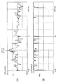
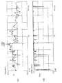
図5には、実際の画像形成装置に光走査装置10を組み込んだ状態で補強部材の無いミラーの振動を振動解析装置を用いて解析した結果が示されている(図5(A)は振動伝達関数(周波数応答関数)、図5(B)はコヒーレント関数を示している。)。試験の結果、ミラー単体の固有値は147Hzであった。
FIG. 5 shows a result of analyzing the vibration of a mirror without a reinforcing member using a vibration analysis device in a state where the
一方、図6は、補強部材をミラーの両側部、及び裏面に接着したものをブラケットに取り付けて振動レベルを実測した結果である(図2の構成)。ミラーの固有値は194Hzに上がっており、ミラー単体に対して剛性が上がっていることが分かる。また、振動伝達係数も低減されていることが分かる。 On the other hand, FIG. 6 shows the result of actually measuring the vibration level by attaching the reinforcing member bonded to both sides and the back surface of the mirror to the bracket (configuration of FIG. 2). The eigenvalue of the mirror is increased to 194 Hz, and it can be seen that the rigidity of the mirror is increased. It can also be seen that the vibration transfer coefficient is also reduced.
なお、本参考例では、ミラー26の保持構造を説明したが、ミラー28の保持構造もミラー26と同様である。
[第1の実施形態]
次に、本発明の第1の実施形態に係る光走査装置10を図7に従って説明する。なお、前述した参考例と同一構成には同一符号を付し、その説明は省略する。
In this reference example , the holding structure of the
[First Embodiment]
Next, the
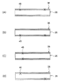
本実施形態では、図7(B)に示すように、補強部材36の連結部36Cとミラー26の裏面26Cとの間に隙間が設けられており、連結部36Cとミラー26の裏面26Cとが接着されていない。
In this embodiment, as shown in FIG. 7B, a gap is provided between the connecting
即ち、本実施形態では、補強部材36は、ミラー26の両側部のみで接着固定されている。
That is, in the present embodiment, the reinforcing
本実施形態の補強部材36は、連結部36Cが質量、側部36A、及び側部36Bと連結部36Cとの境界付近がバネに相当するダイナミックダンパとなっている。
In the reinforcing
本実施形態では、外部からの振動エネルギーに対して上記ダイナミックダンパ部分が振動することによって、本来ミラー自身が振動させられていた振動エネルギーを減少させることでミラー26の振動を抑制することができ、補強部材36によるミラー26の剛性向上との相乗効果により、さらにミラー26の振動を抑制することが出来る。
In this embodiment, the vibration of the
なお、本実施形態では、補強部材36の長手方向両側にダイナミクダンパが構成されることになるが、何れか一方にダイナミックダンパが構成されていれば振動抑制効果はある。
In this embodiment, dynamic dampers are formed on both sides of the reinforcing
図8は、上述したように両側にダイナミックダンパを構成した補強部材をミラーに接着したものをブラケットに取り付けてミラーの振動を解析した結果である。ミラーの固有値は194Hzであり、さらに振動伝達係数が24dBとなっている。 FIG. 8 shows the result of analyzing the vibration of the mirror by attaching the reinforcing member having the dynamic damper on both sides bonded to the mirror as described above to the bracket. The eigenvalue of the mirror is 194 Hz, and the vibration transfer coefficient is 24 dB.
参考例(ダイナミックダンパを持たない)の振動伝達係数35.7dBに対し、第1の実施形態(ダイナミックダンパ付き)は24dBであるので、ミラーの振動がより抑えられていることが分かる。
[第2の実施形態]
次に、本発明の第2の実施形態に係る光走査装置10を図9に従って説明する。なお、前述した実施形態と同一構成には同一符号を付し、その説明は省略する。
Since the first embodiment (with a dynamic damper) is 24 dB with respect to the vibration transmission coefficient of 35.7 dB in the reference example (without the dynamic damper), it can be seen that the vibration of the mirror is further suppressed.
[ Second Embodiment ]
Next, an
本実施形態の補強部材36は図9(A)に示すような形状であり、図9(B)に示すような形状の金属板48に孔42をプレス等で打ち抜き後、2点鎖線で示す部分で折り曲げることで断面コ字形状に形成したものである。
The reinforcing
本実施形態の補強部材36は、側部36Aの中央部分と側部36Bの中央部分が連結部36Cで連結されており、連結部36Cの両側には、振動部36Dが一体的に設けられている。
In the reinforcing
本実施形態も孔42に接着剤を流し込んでミラー26(図9では図示せず)の両側部の複数箇所のみで補強部材36を固定し、連結部36C、及び振動部36Dをミラー26の裏面より離す。
Also in this embodiment, an adhesive is poured into the
本実施形態では、振動部36Dがダイナミックダンパ(質量、及びバネ)の役目をしており、外部からの振動エネルギーに対して上記ダイナミックダンパ部分が振動することによって、ミラー26の振動が抑制される。
[第3の実施形態]
次に、本発明の第3の実施形態に係る光走査装置10を図10に従って説明する。なお、前述した実施形態と同一構成には同一符号を付し、その説明は省略する。
In the present embodiment, the vibrating
[ Third Embodiment ]
Next, an
図10に示すように、本実施形態の補強部材36は、ミラー26の端面26Aのみに接着剤46で固定されており、ミラー26の端面26Bとの間には弾性体50が介在している。
As shown in FIG. 10, the reinforcing
ここでいう弾性体50とは、ミラー26、及び補強部材36よりも剛性の低い、例えば、ゴム、合成樹脂等であり、その形態はスポンジ状であっても良い。
Here, the
これにより、減衰性を向上させることができ、また、ミラー26の幅W1と補強部材36の側部36Aと側部36Bとの間隔寸法W2との寸法公差を緩和することもできる。
Thereby, the attenuation can be improved, and the dimensional tolerance between the width W 1 of the mirror 26 and the distance dimension W 2 between the
なお、図示はしないが、補強部材36の連結部36Cとミラー26の裏面26Cとの間弾性体を介在させることもできる。
[第4の実施形態]
次に、本発明の第4の実施形態に係る光走査装置10を図11に従って説明する。なお、前述した実施形態と同一構成には同一符号を付し、その説明は省略する。
Although not shown, an elastic body may be interposed between the connecting
[ Fourth Embodiment ]
Next, an
図11には、ミラー26と補強部材36との接着部位が異なる例(概略)が示されている。なお、図11において、×印が接着部位(接着剤46)を示している。
FIG. 11 shows an example (schematic) in which the adhesion portion between the
前述した実施形態では、接着位置が補強部材36の長手方向中心部を対称軸として左右対称であり、ミラー26の両側部を接着していたが、接着位置は左右対称でなくても良く、場合によってはミラー26の一方の側部のみでも良い。
[その他の実施形態]
接着点を足すつなげることで補強部材36とミラー26間を一様に接着しても良い。また、上記実施形態では、ミラー26と補強部材36を接着剤46を用いて接着したが、接着剤の代わりに両面テープを用いても良い。
In the above-described embodiment, the bonding position is symmetric with respect to the longitudinal center of the reinforcing
[Other Embodiments]
The reinforcing
補強部材36の材質は金属に限らず、ミラー26を補強できれば合成樹脂等であっても良い。
The material of the reinforcing
10 光走査装置
12 レーザー光源
18 シリンドリカルレンズ(光学系)
20 回転多面鏡(偏向手段)
22 fθレンズ(光学系)
26 ミラー(反射鏡)
28 ミラー(反射鏡)
36 補強部材
36C 連結部(振動部)
50 弾性体
10
20 Rotating polygon mirror (deflection means)
22 fθ lens (optical system)
26 Mirror (Reflector)
28 Mirror (Reflector)
36 Reinforcing
50 Elastic body
Claims (4)
出射された光ビームを主走査方向に偏向させる偏向手段と、
偏向された光ビームを被走査面上に結像させる光学系と、
前記偏向手段と被走査面との間に設けられて光ビームを反射する反射鏡と、
を備え、
前記反射鏡は、装置本体のフレームに取り付けられ、前記反射鏡には、補強部材が複数箇所で点状に固定されていると共に、
前記補強部材は、前記反射鏡の端面に固定される側部と、前記側部に連結され、前記反射鏡及び前記装置本体のフレームと離間して配置される振動部とを有し、前記振動部は、振動入力時に前記反射鏡の振動を抑えるように振動する、ことを特徴とする光走査装置。 A light source that emits a light beam;
Deflection means for deflecting the emitted light beam in the main scanning direction;
An optical system for imaging the deflected light beam on the surface to be scanned;
A reflecting mirror provided between the deflecting means and the surface to be scanned and reflecting a light beam;
With
The reflector is attached to a frame of the apparatus main body , and reinforcing members are fixed to the reflector in a dotted manner at a plurality of locations.
The reinforcing member includes a side portion fixed to an end surface of the reflecting mirror, and a vibrating portion connected to the side portion and disposed apart from the reflecting mirror and the frame of the apparatus main body. The unit vibrates so as to suppress the vibration of the reflecting mirror at the time of vibration input.
Priority Applications (1)
| Application Number | Priority Date | Filing Date | Title |
|---|---|---|---|
| JP2004342603A JP4635581B2 (en) | 2004-11-26 | 2004-11-26 | Optical scanning device |
Applications Claiming Priority (1)
| Application Number | Priority Date | Filing Date | Title |
|---|---|---|---|
| JP2004342603A JP4635581B2 (en) | 2004-11-26 | 2004-11-26 | Optical scanning device |
Publications (2)
| Publication Number | Publication Date |
|---|---|
| JP2006154108A JP2006154108A (en) | 2006-06-15 |
| JP4635581B2 true JP4635581B2 (en) | 2011-02-23 |
Family
ID=36632524
Family Applications (1)
| Application Number | Title | Priority Date | Filing Date |
|---|---|---|---|
| JP2004342603A Expired - Fee Related JP4635581B2 (en) | 2004-11-26 | 2004-11-26 | Optical scanning device |
Country Status (1)
| Country | Link |
|---|---|
| JP (1) | JP4635581B2 (en) |
Families Citing this family (2)
| Publication number | Priority date | Publication date | Assignee | Title |
|---|---|---|---|---|
| JP4839165B2 (en) * | 2006-09-15 | 2011-12-21 | 株式会社リコー | Mirror reinforcing structure, optical scanning device, image reading device, and image forming device |
| JP4877223B2 (en) * | 2007-12-27 | 2012-02-15 | コニカミノルタビジネステクノロジーズ株式会社 | Laser scanning optical device and mirror unit |
Family Cites Families (1)
| Publication number | Priority date | Publication date | Assignee | Title |
|---|---|---|---|---|
| JPH0915523A (en) * | 1995-06-30 | 1997-01-17 | Canon Inc | Optical scanning device |
-
2004
- 2004-11-26 JP JP2004342603A patent/JP4635581B2/en not_active Expired - Fee Related
Also Published As
| Publication number | Publication date |
|---|---|
| JP2006154108A (en) | 2006-06-15 |
Similar Documents
| Publication | Publication Date | Title |
|---|---|---|
| TWI451148B (en) | Mount, lithography objective, projection exposure machine and method for producing semiconductor components | |
| KR101343314B1 (en) | light beam scanning device | |
| JPWO2008152979A1 (en) | Optical scanning sensor | |
| CN112117930A (en) | Vibration wave motor and driving apparatus | |
| US7548362B2 (en) | Optical deflecting device and image forming apparatus using the same | |
| JP4645251B2 (en) | Optical device | |
| JP4635581B2 (en) | Optical scanning device | |
| JP4140226B2 (en) | Optical scanning device | |
| JP5652154B2 (en) | Optical scanning element and image display device provided with the optical scanning element | |
| JP4467822B2 (en) | Scanning optical device | |
| JP2011027881A (en) | Optical scanner | |
| JP4591059B2 (en) | Optical scanning device | |
| JP3458639B2 (en) | Optical scanning device | |
| JP3836401B2 (en) | Optical device | |
| CN100460704C (en) | Imaging device and light scanning unit thereof | |
| JP4687705B2 (en) | Optical scanning device | |
| JP2002242898A (en) | Piezoelectric fan | |
| JP2016218102A (en) | Dynamic vibration absorber, and optical device and image forming apparatus including the same | |
| JP3653059B2 (en) | Document reader | |
| JPH0425613B2 (en) | ||
| JP4023941B2 (en) | Optical scanning device | |
| JPH11231245A (en) | Elongated optical member and its supporting mechanism in optical writing device of optical equipment | |
| JPH08189547A (en) | Vibration control device | |
| JP2005107064A (en) | Laser scanning device | |
| JPH0373909A (en) | Field curvature compensating device in scanning optical device |
Legal Events
| Date | Code | Title | Description |
|---|---|---|---|
| A621 | Written request for application examination |
Free format text: JAPANESE INTERMEDIATE CODE: A621 Effective date: 20071016 |
|
| A977 | Report on retrieval |
Free format text: JAPANESE INTERMEDIATE CODE: A971007 Effective date: 20100330 |
|
| A131 | Notification of reasons for refusal |
Free format text: JAPANESE INTERMEDIATE CODE: A131 Effective date: 20100525 |
|
| A521 | Request for written amendment filed |
Free format text: JAPANESE INTERMEDIATE CODE: A523 Effective date: 20100726 |
|
| A131 | Notification of reasons for refusal |
Free format text: JAPANESE INTERMEDIATE CODE: A131 Effective date: 20100817 |
|
| A521 | Request for written amendment filed |
Free format text: JAPANESE INTERMEDIATE CODE: A523 Effective date: 20101005 |
|
| TRDD | Decision of grant or rejection written | ||
| A01 | Written decision to grant a patent or to grant a registration (utility model) |
Free format text: JAPANESE INTERMEDIATE CODE: A01 Effective date: 20101026 |
|
| A01 | Written decision to grant a patent or to grant a registration (utility model) |
Free format text: JAPANESE INTERMEDIATE CODE: A01 |
|
| A61 | First payment of annual fees (during grant procedure) |
Free format text: JAPANESE INTERMEDIATE CODE: A61 Effective date: 20101108 |
|
| FPAY | Renewal fee payment (event date is renewal date of database) |
Free format text: PAYMENT UNTIL: 20131203 Year of fee payment: 3 |
|
| R150 | Certificate of patent or registration of utility model |
Ref document number: 4635581 Country of ref document: JP Free format text: JAPANESE INTERMEDIATE CODE: R150 Free format text: JAPANESE INTERMEDIATE CODE: R150 |
|
| LAPS | Cancellation because of no payment of annual fees |