JP4635563B2 - Electric blower - Google Patents
Electric blower Download PDFInfo
- Publication number
- JP4635563B2 JP4635563B2 JP2004320217A JP2004320217A JP4635563B2 JP 4635563 B2 JP4635563 B2 JP 4635563B2 JP 2004320217 A JP2004320217 A JP 2004320217A JP 2004320217 A JP2004320217 A JP 2004320217A JP 4635563 B2 JP4635563 B2 JP 4635563B2
- Authority
- JP
- Japan
- Prior art keywords
- electric blower
- opening
- centrifugal fan
- air
- fan
- Prior art date
- Legal status (The legal status is an assumption and is not a legal conclusion. Google has not performed a legal analysis and makes no representation as to the accuracy of the status listed.)
- Expired - Lifetime
Links
Images

Classifications
-
- A—HUMAN NECESSITIES
- A47—FURNITURE; DOMESTIC ARTICLES OR APPLIANCES; COFFEE MILLS; SPICE MILLS; SUCTION CLEANERS IN GENERAL
- A47L—DOMESTIC WASHING OR CLEANING; SUCTION CLEANERS IN GENERAL
- A47L5/00—Structural features of suction cleaners
- A47L5/12—Structural features of suction cleaners with power-driven air-pumps or air-compressors, e.g. driven by motor vehicle engine vacuum
-
- F—MECHANICAL ENGINEERING; LIGHTING; HEATING; WEAPONS; BLASTING
- F04—POSITIVE - DISPLACEMENT MACHINES FOR LIQUIDS; PUMPS FOR LIQUIDS OR ELASTIC FLUIDS
- F04D—NON-POSITIVE-DISPLACEMENT PUMPS
- F04D29/00—Details, component parts, or accessories
- F04D29/40—Casings; Connections of working fluid
- F04D29/42—Casings; Connections of working fluid for radial or helico-centrifugal pumps
- F04D29/44—Fluid-guiding means, e.g. diffusers
- F04D29/441—Fluid-guiding means, e.g. diffusers especially adapted for elastic fluid pumps
- F04D29/444—Bladed diffusers
-
- F—MECHANICAL ENGINEERING; LIGHTING; HEATING; WEAPONS; BLASTING
- F04—POSITIVE - DISPLACEMENT MACHINES FOR LIQUIDS; PUMPS FOR LIQUIDS OR ELASTIC FLUIDS
- F04D—NON-POSITIVE-DISPLACEMENT PUMPS
- F04D25/00—Pumping installations or systems
- F04D25/02—Units comprising pumps and their driving means
- F04D25/08—Units comprising pumps and their driving means the working fluid being air, e.g. for ventilation
- F04D25/082—Units comprising pumps and their driving means the working fluid being air, e.g. for ventilation the unit having provision for cooling the motor
-
- F—MECHANICAL ENGINEERING; LIGHTING; HEATING; WEAPONS; BLASTING
- F04—POSITIVE - DISPLACEMENT MACHINES FOR LIQUIDS; PUMPS FOR LIQUIDS OR ELASTIC FLUIDS
- F04D—NON-POSITIVE-DISPLACEMENT PUMPS
- F04D29/00—Details, component parts, or accessories
- F04D29/40—Casings; Connections of working fluid
- F04D29/42—Casings; Connections of working fluid for radial or helico-centrifugal pumps
- F04D29/44—Fluid-guiding means, e.g. diffusers
- F04D29/441—Fluid-guiding means, e.g. diffusers especially adapted for elastic fluid pumps
-
- F—MECHANICAL ENGINEERING; LIGHTING; HEATING; WEAPONS; BLASTING
- F04—POSITIVE - DISPLACEMENT MACHINES FOR LIQUIDS; PUMPS FOR LIQUIDS OR ELASTIC FLUIDS
- F04D—NON-POSITIVE-DISPLACEMENT PUMPS
- F04D29/00—Details, component parts, or accessories
- F04D29/58—Cooling; Heating; Diminishing heat transfer
- F04D29/5806—Cooling the drive system
-
- F—MECHANICAL ENGINEERING; LIGHTING; HEATING; WEAPONS; BLASTING
- F04—POSITIVE - DISPLACEMENT MACHINES FOR LIQUIDS; PUMPS FOR LIQUIDS OR ELASTIC FLUIDS
- F04D—NON-POSITIVE-DISPLACEMENT PUMPS
- F04D29/00—Details, component parts, or accessories
- F04D29/58—Cooling; Heating; Diminishing heat transfer
- F04D29/582—Cooling; Heating; Diminishing heat transfer specially adapted for elastic fluid pumps
- F04D29/584—Cooling; Heating; Diminishing heat transfer specially adapted for elastic fluid pumps cooling or heating the machine
Landscapes
- Engineering & Computer Science (AREA)
- Mechanical Engineering (AREA)
- General Engineering & Computer Science (AREA)
- Physics & Mathematics (AREA)
- Thermal Sciences (AREA)
- Structures Of Non-Positive Displacement Pumps (AREA)
- Motor Or Generator Cooling System (AREA)
Description
本発明は、電気掃除機等に使用される電動送風機に関する。 The present invention relates to an electric blower used for a vacuum cleaner or the like.
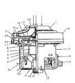
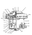
まず、最も一般的に用いられる電気掃除機等に使用される電動送風機の構成について図5を用いて簡単に説明する。 First, the configuration of an electric blower used for the most commonly used vacuum cleaner or the like will be briefly described with reference to FIG.
符号2は、界磁コア3に界磁巻線3aを施してなるステータである。符号5は軸6に通された電機子コア7に電機子巻線8を施し、整流子9を同軸上に配置して軸6の両端に設けられた軸受10によって回転自在に固定されたロータである。ステータ2およびロータ5は負荷側ブラケット11、反負荷側ブラケット12に固定され、反負荷側ブラケット12に一対のカーボンブラシ(図示せず)をブラシ保持器14を介してネジ15にて固定されることでモータ16を形成している。符号20は排気口である。また、軸6には遠心ファン17が備えられ、遠心ファン17の外周部に通風路を形成するエアガイド18が配されており、エアガイド18は表面の隣り合う静翼21a間によって構成される複数の通路をもつディフューザ部21と、流れをエアガイド18裏面へと導く流れ変更部22、さらに戻り通路23により構成される。そして、ファンケース19がこれらを覆うように取り付けられ電動送風機1となる。吸気口25が備えられている。
上記構成において、電力が供給されると界磁巻線3aを伝導した電流がカーボンブラシ(図示せず)を通って整流子9に伝わり、界磁コア3で発生した磁束と電機子巻線8を通る電流との間で力が発生し、ロータ5が回転する。次にロータ5が回転することにより、ロータ5の軸6に固定された遠心ファン17が回転し、遠心ファン17内の空気を増速し、増速された空気はエアガイド18のディフューザ部21を通り、減速されて流れ変更部22へと入り込み、方向を180度転換されて、戻り通路23を通り、モータ16へと導かれる。そしてその後、ロータ5、ステータ2、カーボンブラシを冷却しながら、反負荷側ブラケット12の排気口20より排出される。
In the above configuration, when electric power is supplied, a current conducted through the
上記のような一般的な電動送風機の構成では、近年の家庭用掃除機の高吸込仕事率化に伴う電動送風機の高効率化には限界があり、それを補うべく考案された例として、特開2001−133865号のマイクロフィルムに開示された例などがある。それによると図6のように、ファンケース19の外周に設けたスリット26の吸気側の端部から反吸気側の端部に向けて、ひさし状の切り起こし26aを設けた構成とし、ディフューザ部21を通過した空気の一部を外部に放出する開口部を設け電動送風機の効率を向上する構成のものが知られている。
解決しようとする問題点は、上記のような電動送風機にあっては、ファンケースの外周に設けたスリットの吸気側の端部から反吸気側の端部に向けて、ひさし状の切り起こしを設け、反ファンケース吸込口側に向かって開口された構成であるため、ディフューザ部を通過した空気の一部を外部に放出する開口部の面積が十分に確保できず、電動送風機の効率向上に限界があり、さらなる電動送風機の効率向上が図れなかった。 The problem to be solved is that, in the electric blower as described above, an eaves-like cut is raised from the suction side end of the slit provided on the outer periphery of the fan case to the end opposite to the suction side. Since it is configured to open toward the fan case suction port side, the area of the opening that releases part of the air that has passed through the diffuser part to the outside cannot be secured sufficiently, improving the efficiency of the electric blower There was a limit, and the efficiency of the electric blower could not be further improved.
上記課題を解決するために本発明は、巻線を施したステータ及び高速で回転するロータを有し、それらをブラケットで覆ったモータと、前記ロータの軸に固定され共に回転する遠心ファンと遠心ファン外周に複数の隣り合う静翼で形成されたディフューザ部を備えたエアガイドと、前記遠心ファンを覆うように前記ブラケットに圧入固定されたファンケースを備え、遠心ファンで発生させた気流によってモータの冷却を行う形態の電動送風機で、前記ファンケースの外周部にはディフューザ部を通過した空気の一部を外部に放出する開口部とその開口部の一部を覆うツバ状の凸部を構成したものである。 In order to solve the above-mentioned problems, the present invention has a stator with windings and a rotor that rotates at high speed, a motor that covers them with a bracket, a centrifugal fan that is fixed to the shaft of the rotor and rotates together with the motor. An air guide provided with a diffuser portion formed by a plurality of adjacent stationary blades on the outer periphery of the fan, and a fan case press-fitted and fixed to the bracket so as to cover the centrifugal fan, and a motor by airflow generated by the centrifugal fan In the electric blower in the form of cooling the fan case, the outer peripheral portion of the fan case is configured with an opening that discharges a part of the air that has passed through the diffuser portion to the outside and a flange-like convex portion that covers a part of the opening It is a thing.
本発明の電動送風機によれば、ファンケースの外周部には、ディフューザを通過した空気の一部を外部に放出する開口部とその開口部の一部を覆うツバ状の凸部を構成しているので、ディフューザを通過した空気の一部を外部に放出する開口部の面積が十分に確保することができる。 According to the electric blower of the present invention, the outer peripheral portion of the fan case is configured with an opening that discharges a part of the air that has passed through the diffuser to the outside, and a flange-like convex portion that covers a part of the opening. Therefore, the area of the opening that discharges a part of the air that has passed through the diffuser to the outside can be sufficiently secured.
また、ファンケース外周に設けた、開口部を覆うツバ部の幅を遠心ファン回転方向に対して徐々に小さくするようツバ形状を形成したので、ディフューザ部で減速された空気を効率よく外気へと放出することができる。 In addition, since the flange shape is formed so that the width of the flange portion provided on the outer periphery of the fan case and gradually covering the opening portion is gradually reduced with respect to the centrifugal fan rotation direction, the air decelerated at the diffuser portion is efficiently transferred to the outside air. Can be released.
また、開口部断面積に対してツバ部が開口部を30〜75%覆うように設定したことで、モータを冷却する風量と、ファンケース外周から放出する風量をバランス良く分配することができる。 In addition, since the brim portion is set so as to cover 30 to 75% of the opening cross-sectional area, the air volume for cooling the motor and the air volume discharged from the outer periphery of the fan case can be distributed in a well-balanced manner.
したがって、モータの冷却は十分に行いつつ、高効率の電動送風機を提供することができる。 Therefore, a highly efficient electric blower can be provided while sufficiently cooling the motor.
本発明の請求項1記載の発明は、巻線を施したステータ及び高速で回転するロータを有し、それらをブラケットで覆ったモータと、前記ロータの軸に固定され共に回転する遠心ファンと遠心ファン外周に複数の隣り合う静翼で形成されたディフューザ部を備えたエアガイドと、前記遠心ファンを覆うように前記ブラケットに圧入固定されたファンケースを備え、遠心ファンで発生させた気流によってモータの冷却を行う形態の電動送風機で、前記ファンケースの外周部には、ディフューザ部を通過した空気の一部を外部に放出する開口部とその開口部の一部を覆うツバ状の凸部を設けたことで、電動送風機の効率を向上させることができる。
The invention according to
また、本発明の請求項2記載の発明は、上記請求項1記載の発明において、ファンケース外周に設けた、開口部を覆うツバ部の幅を遠心ファン回転方向に対して徐々に小さくするようツバ形状を形成したことにより、ディフューザ部で減速された空気の一部を効率よく外気へと放出することができ、電動送風機の効率を向上させることができる。 According to a second aspect of the present invention, in the first aspect of the present invention, the width of the brim portion covering the opening provided on the outer periphery of the fan case is gradually reduced with respect to the centrifugal fan rotation direction. By forming the brim shape, part of the air decelerated at the diffuser portion can be efficiently discharged to the outside air, and the efficiency of the electric blower can be improved.
また、本発明の請求項3記載の発明は、上記請求項1または2記載の発明において、開口部断面積に対してツバ部が開口部を30〜75%覆うように設定したことにより、モータを冷却する風量と、ファンケース外周から放出する風量をバランス良く分配したので、モータの冷却は十分に行いつつ、効率の高い電動送風機を提供することができる。
The invention according to
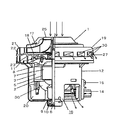
本発明の実施例1について図1を用いて説明する。なお従来例と同一構成部品については同一符号を付して、その説明を省略する。図1は、本実施例の電動送風機の半断面図を示している。27はファンケース19外周上に設けられた開口部で、28は開口部27の一部を覆うツバ状の凸部であり、この開口部27の円周方向の幅は、ディフューザ部21の隣り合う静翼29間で形成される通路が、流れを180度転換させる流れ変更部22へ突入する直前の円周方向の通路幅と略同一となっているとともに、前記開口部27とツバ状の凸部28は、通路の略延長上に配置され、効率よく排気が放出されるようになっている。また、図中の矢印は、吸気口25より吸い込まれた空気の流れを示している。
A first embodiment of the present invention will be described with reference to FIG. The same components as those in the conventional example are denoted by the same reference numerals, and the description thereof is omitted. FIG. 1 shows a half sectional view of the electric blower of this embodiment.
上記の構成において、動作を説明すると電力が供給されると、従来例と同様、電機子5が回転し、遠心ファン17で発生した気流が、エアガイド18のディフューザ部21を通り、一部はそのまま外気へと放出され、残りの空気は、流れ変更部22で流れを180度転換されると、同部での曲がり損失が増大するが、本実施例ではファンケース19外周上に設けられた複数の開口部27と開口部27の一部を覆うツバ状の凸部28が、ディフューザ部21外周に効率よく配設されているので一部の空気がツバ状の凸部28および開口部27より放出され損失は低減される。
In the above configuration, the operation will be described. When electric power is supplied, the
このように、本発明の電動送風機によれば、エアガイド18での曲がり損失をより低減できるので、効率の良い電動送風機を得ることができる。
Thus, according to the electric blower of this invention, since the bending loss in the
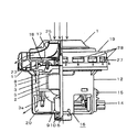
実施例2について図2を用いて説明する。なお、実施例1と同一構成部品については同一符号を付して、その説明を省略する。図2において、30はファンケース19開口部27の一部を覆うツバ部であり、このツバ部30は、開口部27を覆う幅を回転ファン17の回転方向に対して徐々に小さくするように形成されている。また、図中の矢印は、吸気口25より吸い込まれた空気の流れを示している。
A second embodiment will be described with reference to FIG. The same components as those in the first embodiment are denoted by the same reference numerals, and the description thereof is omitted. In FIG. 2,
上記の構成において、動作を説明すると電力が供給されると、従来例と同様、電機子5が回転し、遠心ファン17で発生した気流が、エアガイド18のディフューザ部21を通り、一部はそのまま外気へと放出され、残りの空気は、流れ変更部22で流れを180度転換されると、同部での曲がり損失が増大するが、本実施例ではファンケース19外周上に設けられた複数のツバ部30が遠心ファン17の回転方向に対して徐々に小さくするように形成されているので、ディフューザ部を通過した空気の一部がスムーズに外気へ放出されるため、開口部27での空気の衝突損失を低減される。
In the above configuration, the operation will be described. When electric power is supplied, the
このように、本発明の電動送風機によれば、ファンケース19の外周上に設けられた開口部27での衝突損失をより低減できるので、効率の良い電動送風機を得ることができる。
Thus, according to the electric blower of this invention, since the collision loss in the
実施例3について図3を用いて説明する。なお、実施例1と同一構成部品については同一符号を付して、その説明を省略する。27はファンケース19外周上に設けられた開口部で、28は開口部27の一部を覆うツバ状の凸部で、第1の実施例と同一であるが、開口部断面積に対してツバ状の凸部28が開口部27を30〜75%覆うように設定し、配設されている。
Example 3 will be described with reference to FIG. The same components as those in the first embodiment are denoted by the same reference numerals, and the description thereof is omitted.
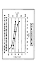
上記の構成において、ファンケース19から排気の一部を放出すると、電動送風機1の効率は改善できるが、その反面モータ16を冷却する風量が減少し、電動送風機1の温度は上昇する。図4には、開口部断面積に対しツバ状の凸部28が覆う断面積比に対する電動送風機1の効率と電機子巻線の温度上昇値の関係を示している。これによると断面積比が25%以下になると電機子巻線の温度上昇値が80Kを超え、危険な領域に入ると考えられる。一方、断面積比を80%以上に設定すると電動送風機1の効率改善効果が少なくなる。本実施例では、断面積比がモータ16の冷却を十分行いつつ、電動送風機1の効率改善を最大限行えるよう設定されているので、高効率で信頼性の確保ができた電動送風機を得ることができる。
In the above configuration, when a part of the exhaust gas is discharged from the
本発明の電動送風機は、吸込み仕事率向上に最適であり、家庭用や産業用掃除機用途などに有用である。 The electric blower of the present invention is optimal for improving the suction work rate and is useful for household and industrial vacuum cleaner applications.
1 電動送風機
16 モータ
17 遠心ファン
19 ファンケース
27 開口部
28 ツバ状の凸部
30 ツバ部
DESCRIPTION OF
Claims (3)
The electric blower according to claim 1 or 2, wherein the brim portion is set to cover 30 to 75% of the opening with respect to the sectional area of the opening.
Priority Applications (5)
| Application Number | Priority Date | Filing Date | Title |
|---|---|---|---|
| JP2004320217A JP4635563B2 (en) | 2004-11-04 | 2004-11-04 | Electric blower |
| PCT/JP2005/019972 WO2006049115A1 (en) | 2004-11-04 | 2005-10-31 | Electric blower |
| US11/577,549 US7845917B2 (en) | 2004-11-04 | 2005-10-31 | Electric blower |
| GB0707468A GB2438039B (en) | 2004-11-04 | 2005-10-31 | Electric blower |
| CN200580037652A CN100575714C (en) | 2004-11-04 | 2005-10-31 | Electric blower |
Applications Claiming Priority (1)
| Application Number | Priority Date | Filing Date | Title |
|---|---|---|---|
| JP2004320217A JP4635563B2 (en) | 2004-11-04 | 2004-11-04 | Electric blower |
Publications (2)
| Publication Number | Publication Date |
|---|---|
| JP2006132369A JP2006132369A (en) | 2006-05-25 |
| JP4635563B2 true JP4635563B2 (en) | 2011-02-23 |
Family
ID=36319122
Family Applications (1)
| Application Number | Title | Priority Date | Filing Date |
|---|---|---|---|
| JP2004320217A Expired - Lifetime JP4635563B2 (en) | 2004-11-04 | 2004-11-04 | Electric blower |
Country Status (5)
| Country | Link |
|---|---|
| US (1) | US7845917B2 (en) |
| JP (1) | JP4635563B2 (en) |
| CN (1) | CN100575714C (en) |
| GB (1) | GB2438039B (en) |
| WO (1) | WO2006049115A1 (en) |
Families Citing this family (13)
| Publication number | Priority date | Publication date | Assignee | Title |
|---|---|---|---|---|
| CN101832295B (en) * | 2010-01-18 | 2012-05-02 | 重庆长安汽车股份有限公司 | Blower for automobile air conditioning system |
| DE102011006546B4 (en) * | 2011-03-31 | 2013-07-04 | BSH Bosch und Siemens Hausgeräte GmbH | blower assembly |
| JP5762157B2 (en) | 2011-06-10 | 2015-08-12 | 三菱重工業株式会社 | Centrifugal blower and vehicle air conditioner equipped with the same |
| NL2011129C2 (en) | 2013-07-09 | 2015-01-12 | Eco Logical Entpr B V | COMPACT ELECTRICAL DEVICE AND ELECTRODYNAMIC LOUDSPEAKER, ELECTRIC MOTOR, SCREENER AND ADJUSTABLE COUPLING BASED ON THEM. |
| NL2011128C2 (en) * | 2013-07-09 | 2015-01-12 | Eco Logical Entpr B V | ROTATING DEVICE, FOR EXAMPLE A AIR MOUNT, SUCH AS A FAN, A PROPELLER OR LIFT SCREW, A WATER TURBINE OR A WIND TURBINE. |
| JP6375516B2 (en) * | 2014-08-20 | 2018-08-22 | パナソニックIpマネジメント株式会社 | Electric blower and electric vacuum cleaner using it |
| US11209006B2 (en) | 2014-09-09 | 2021-12-28 | Twin City Fan Companies, Ltd. | Motor cooling device and method |
| JP6438860B2 (en) | 2015-07-31 | 2018-12-19 | ミネベアミツミ株式会社 | Centrifugal fan |
| EP3348843A4 (en) * | 2015-09-10 | 2019-04-17 | Nidec Corporation | Blower device and cleaner |
| DE102016110923A1 (en) * | 2016-06-15 | 2017-12-21 | Miele & Cie. Kg | Blower device for a vacuum cleaner, method for operating a blower device, control unit and vacuum cleaner |
| JP7354569B2 (en) * | 2019-03-28 | 2023-10-03 | ニデック株式会社 | Air blower and vacuum cleaner |
| KR102334621B1 (en) * | 2019-07-10 | 2021-12-03 | 엘지전자 주식회사 | Fan Motor |
| CN112943698A (en) * | 2019-12-11 | 2021-06-11 | 鼎朋企业股份有限公司 | Air suction motor of dust suction device |
Family Cites Families (13)
| Publication number | Priority date | Publication date | Assignee | Title |
|---|---|---|---|---|
| DE7810865U1 (en) * | 1978-04-12 | 1978-09-21 | Dolmar Maschinen-Fabrik Gmbh & Co, 2000 Hamburg | EXHAUST SILENCER FOR EXHAUST DEVICES OF COMBUSTION MACHINES, IN PARTICULAR OF COMBUSTION MACHINE-DRIVEN HAND APPLIANCES |
| JPS5522913A (en) | 1978-08-04 | 1980-02-19 | Nec Corp | Box structure of printer |
| JPH06100195B2 (en) | 1989-06-19 | 1994-12-12 | 三洋電機株式会社 | Electric blower |
| JPH1026099A (en) | 1996-07-09 | 1998-01-27 | Mitsubishi Electric Corp | Electric blower |
| US5749704A (en) * | 1997-01-06 | 1998-05-12 | Wagner Spray Tech Corporation | Heat gun fan assembly |
| JP2001012395A (en) | 1999-06-25 | 2001-01-16 | Sanyo Electric Co Ltd | Electric fan |
| JP4568946B2 (en) * | 2000-03-28 | 2010-10-27 | パナソニック株式会社 | Electric blower and vacuum cleaner using it |
| JP3838071B2 (en) * | 2001-10-30 | 2006-10-25 | 松下電器産業株式会社 | Electric blower and electric vacuum cleaner using the same |
| GB0202839D0 (en) * | 2002-02-07 | 2002-03-27 | Johnson Electric Sa | Blower motor |
| ES2320795T3 (en) * | 2002-09-20 | 2009-05-28 | Panasonic Corporation | ELECTRIC BLOWER AND VACUUM CLEANER PROVIDED OF THE SAME. |
| JP2004169592A (en) * | 2002-11-19 | 2004-06-17 | Matsushita Electric Ind Co Ltd | Electric blower and vacuum cleaner using the same |
| USD533936S1 (en) * | 2004-11-17 | 2006-12-19 | Matsushita Electric Industrial Co., Ltd. | Fan case |
| JP6100195B2 (en) * | 2014-04-09 | 2017-03-22 | 富士フイルム株式会社 | Imaging device |
-
2004
- 2004-11-04 JP JP2004320217A patent/JP4635563B2/en not_active Expired - Lifetime
-
2005
- 2005-10-31 US US11/577,549 patent/US7845917B2/en active Active
- 2005-10-31 GB GB0707468A patent/GB2438039B/en not_active Expired - Fee Related
- 2005-10-31 WO PCT/JP2005/019972 patent/WO2006049115A1/en not_active Ceased
- 2005-10-31 CN CN200580037652A patent/CN100575714C/en not_active Expired - Lifetime
Also Published As
| Publication number | Publication date |
|---|---|
| JP2006132369A (en) | 2006-05-25 |
| GB2438039A (en) | 2007-11-14 |
| WO2006049115A1 (en) | 2006-05-11 |
| CN101052810A (en) | 2007-10-10 |
| CN100575714C (en) | 2009-12-30 |
| US7845917B2 (en) | 2010-12-07 |
| GB2438039B (en) | 2011-09-21 |
| US20080193305A1 (en) | 2008-08-14 |
| GB0707468D0 (en) | 2007-05-23 |
Similar Documents
| Publication | Publication Date | Title |
|---|---|---|
| CN101188373B (en) | Fan motor | |
| JP4635563B2 (en) | Electric blower | |
| JP2016005377A (en) | Electric blower and electric vacuum cleaner using the same | |
| JP4951588B2 (en) | Electric blower and vacuum cleaner equipped with the same | |
| JP2010190136A (en) | Electric blower and electric vacuum cleaner using the same | |
| JP3581301B2 (en) | Electric blower | |
| WO1997033357A1 (en) | Rotor of rotary machine | |
| JP4568946B2 (en) | Electric blower and vacuum cleaner using it | |
| JP4952061B2 (en) | Electric blower and electric vacuum cleaner using the same | |
| JP2025034604A (en) | Electric blower and vacuum cleaner equipped with same | |
| JP2005207235A (en) | Electric blower and electric vacuum cleaner using the same | |
| JP2006250016A (en) | Electric blower and electric vacuum cleaner using the same | |
| JP2007146746A (en) | Electric blower and electric vacuum cleaner using the same | |
| JP2004116450A (en) | Electric blower and vacuum cleaner using the same | |
| JP2004108317A (en) | Electric blower and vacuum cleaner using the same | |
| JP2002153017A (en) | Electric blower and vacuum cleaner using the same | |
| JP2002127048A (en) | Motor-driven tool | |
| WO2019176625A1 (en) | Electric blower, electric cleaner, and air towel | |
| JP2006299808A (en) | Electric blower and electric vacuum cleaner using the same | |
| JP2013231358A (en) | Electric fan and electric vacuum cleaner using the same | |
| JP2005155397A (en) | Electric blower and electric vacuum cleaner using the same | |
| JP2026007783A (en) | Electric blower and vacuum cleaner equipped with same | |
| JP2005147076A (en) | Electric blower and electric vacuum cleaner using the same | |
| JP2021120572A (en) | Electric blower and vacuum cleaner using the same | |
| JP2005291050A (en) | Centrifugal fan |
Legal Events
| Date | Code | Title | Description |
|---|---|---|---|
| A621 | Written request for application examination |
Free format text: JAPANESE INTERMEDIATE CODE: A621 Effective date: 20071024 |
|
| RD01 | Notification of change of attorney |
Free format text: JAPANESE INTERMEDIATE CODE: A7421 Effective date: 20071113 |
|
| RD01 | Notification of change of attorney |
Free format text: JAPANESE INTERMEDIATE CODE: A7421 Effective date: 20091120 |
|
| TRDD | Decision of grant or rejection written | ||
| A01 | Written decision to grant a patent or to grant a registration (utility model) |
Free format text: JAPANESE INTERMEDIATE CODE: A01 Effective date: 20101026 |
|
| A01 | Written decision to grant a patent or to grant a registration (utility model) |
Free format text: JAPANESE INTERMEDIATE CODE: A01 |
|
| A61 | First payment of annual fees (during grant procedure) |
Free format text: JAPANESE INTERMEDIATE CODE: A61 Effective date: 20101108 |
|
| FPAY | Renewal fee payment (event date is renewal date of database) |
Free format text: PAYMENT UNTIL: 20131203 Year of fee payment: 3 |
|
| R151 | Written notification of patent or utility model registration |
Ref document number: 4635563 Country of ref document: JP Free format text: JAPANESE INTERMEDIATE CODE: R151 |
|
| FPAY | Renewal fee payment (event date is renewal date of database) |
Free format text: PAYMENT UNTIL: 20131203 Year of fee payment: 3 |
|
| EXPY | Cancellation because of completion of term |