JP4635496B2 - Image forming apparatus - Google Patents
Image forming apparatus Download PDFInfo
- Publication number
- JP4635496B2 JP4635496B2 JP2004208239A JP2004208239A JP4635496B2 JP 4635496 B2 JP4635496 B2 JP 4635496B2 JP 2004208239 A JP2004208239 A JP 2004208239A JP 2004208239 A JP2004208239 A JP 2004208239A JP 4635496 B2 JP4635496 B2 JP 4635496B2
- Authority
- JP
- Japan
- Prior art keywords
- density adjustment
- density
- adjustment process
- image
- developing
- Prior art date
- Legal status (The legal status is an assumption and is not a legal conclusion. Google has not performed a legal analysis and makes no representation as to the accuracy of the status listed.)
- Expired - Fee Related
Links
Images

Classifications
-
- G—PHYSICS
- G03—PHOTOGRAPHY; CINEMATOGRAPHY; ANALOGOUS TECHNIQUES USING WAVES OTHER THAN OPTICAL WAVES; ELECTROGRAPHY; HOLOGRAPHY
- G03G—ELECTROGRAPHY; ELECTROPHOTOGRAPHY; MAGNETOGRAPHY
- G03G15/00—Apparatus for electrographic processes using a charge pattern
- G03G15/55—Self-diagnostics; Malfunction or lifetime display
- G03G15/553—Monitoring or warning means for exhaustion or lifetime end of consumables, e.g. indication of insufficient copy sheet quantity for a job
- G03G15/556—Monitoring or warning means for exhaustion or lifetime end of consumables, e.g. indication of insufficient copy sheet quantity for a job for toner consumption, e.g. pixel counting, toner coverage detection or toner density measurement
-
- G—PHYSICS
- G03—PHOTOGRAPHY; CINEMATOGRAPHY; ANALOGOUS TECHNIQUES USING WAVES OTHER THAN OPTICAL WAVES; ELECTROGRAPHY; HOLOGRAPHY
- G03G—ELECTROGRAPHY; ELECTROPHOTOGRAPHY; MAGNETOGRAPHY
- G03G2215/00—Apparatus for electrophotographic processes
- G03G2215/00025—Machine control, e.g. regulating different parts of the machine
- G03G2215/00029—Image density detection
- G03G2215/00033—Image density detection on recording member
- G03G2215/00037—Toner image detection
-
- G—PHYSICS
- G03—PHOTOGRAPHY; CINEMATOGRAPHY; ANALOGOUS TECHNIQUES USING WAVES OTHER THAN OPTICAL WAVES; ELECTROGRAPHY; HOLOGRAPHY
- G03G—ELECTROGRAPHY; ELECTROPHOTOGRAPHY; MAGNETOGRAPHY
- G03G2221/00—Processes not provided for by group G03G2215/00, e.g. cleaning or residual charge elimination
- G03G2221/16—Mechanical means for facilitating the maintenance of the apparatus, e.g. modular arrangements and complete machine concepts
- G03G2221/18—Cartridge systems
- G03G2221/1823—Cartridges having electronically readable memory
Landscapes
- Physics & Mathematics (AREA)
- General Physics & Mathematics (AREA)
- Control Or Security For Electrophotography (AREA)
- Dry Development In Electrophotography (AREA)
Description
本発明は、プリンタ、複写機、ファクシミリ等の画像形成装置に関し、特に、適切な濃度調整制御を行なうことのできる画像形成装置に関する。 The present invention relates to an image forming apparatus such as a printer, a copying machine, and a facsimile, and more particularly to an image forming apparatus capable of performing appropriate density adjustment control.
一般に、カラープリンタなどに設けられる電子写真技術を用いて画像を形成する画像形成装置は、画像データに応じて静電潜像が形成される像担持体と、像担持体の外周面を帯電させる帯電ユニットと、帯電された像担持体の外周面を画像データに応じて露光して静電潜像を形成する露光ユニットと、静電潜像に現像剤であるトナーを供給してトナー像に現像する現像装置と、トナー像を転写対象の媒体に転写させる転写ユニットとを有する。 In general, an image forming apparatus that forms an image using an electrophotographic technique provided in a color printer or the like charges an image carrier on which an electrostatic latent image is formed according to image data, and an outer peripheral surface of the image carrier. A charging unit; an exposure unit that exposes an outer peripheral surface of the charged image carrier in accordance with image data to form an electrostatic latent image; and a toner that is a developer is supplied to the electrostatic latent image to form a toner image. A developing device for developing, and a transfer unit for transferring the toner image to a medium to be transferred.
かかる画像形成装置では、通常、常に良好な画像濃度での画像出力が行えるように、画像の濃度調整という処理を行っている。この濃度調整は、例えば、画像形成装置の電源投入時、所定枚数の画像形成を実行した後、あるいは、像担持体を交換したときなど、像担持体へのトナー像形成についての特性に変化があったと思われる際に実行される。また、この濃度調整は、各運転条件でパッチや細線などのパターンを像担持体上に作像し、そのパターンの濃度等をセンサにより検出して運転条件にフィードバックすることによって行われている。例えば、現像装置が有するトナーを収容したトナーカートリッジのローラ部分に印加する現像バイアスを変化させて、各バイアス値において塗りつぶしのパッチを作像する。そして、それら形成された各パッチの濃度を計測し、それらの値から所望の濃度値になるような現像バイアス値を求めて、その値になるような制御を行なう。 In such an image forming apparatus, a process called image density adjustment is normally performed so that an image can always be output with a good image density. This density adjustment is performed, for example, when the power of the image forming apparatus is turned on, after a predetermined number of image formations are performed, or when the image carrier is replaced, and the characteristics of toner image formation on the image carrier are changed. It is executed when it seems to have been. The density adjustment is performed by forming a pattern such as a patch or a thin line on the image carrier under each operating condition, detecting the density of the pattern with a sensor, and feeding it back to the operating condition. For example, the development bias to be applied to the roller portion of the toner cartridge that contains the toner included in the developing device is changed to form a solid patch at each bias value. Then, the density of each of the formed patches is measured, and a development bias value that achieves a desired density value is obtained from these values, and control is performed so as to obtain that value.
このような濃度調整の制御については、従来より幾つかの提案がなされており、下記特許文献1に記載の装置においては、速度を優先するモードに設定されている際に、前記濃度調整を実施せずに装置の立ち上げ動作を行い、画像出力までの時間短縮を図るという制御方法が開示されている。
Regarding the control of density adjustment, several proposals have been made so far. In the apparatus described in
一方、前記現像装置に装着されるトナーカートリッジには、その装着によりプリンタなどの画像形成装置が本来の性能を発揮できることが保証されているトナーカートリッジ、即ち、画像形成装置の製造元等が製造・販売しているトナーカートリッジと、そうでないトナーカートリッジ、即ち、画像形成装置の製造元が製造・販売に全く関与していないトナーカートリッジがある。以下、前者のトナーカートリッジをプリンタなどの画像形成装置の製造元が品質を保証した品と呼び、後者のトナーカートリッジをプリンタなどの画像形成装置の製造元が品質を確認していない品と呼ぶこととする。本来、画像形成装置には品質が保証された品を装着して使用すべきであるが、製造元が品質を確認していない品も販売されていることから、ユーザが、製造元が品質を確認していない品を装着して使用する場合もある。
以上説明したように、従来から画像形成装置における濃度調整制御というものが行われていたが、かかる制御において、画像形成装置に装着されているトナーカートリッジが前述した品質が保証された品であるか否かについては考慮されていなかった。 As described above, the density adjustment control in the image forming apparatus has been conventionally performed. In this control, whether the toner cartridge mounted on the image forming apparatus has the above-mentioned quality guaranteed. It was not considered whether or not.
通常の場合、画像形成装置には品質が保証された品のトナーカートリッジが装着されると想定されるので、前述した濃度調整も品質が保証されたトナーカートリッジに適した内容で、例えば、前記現像バイアスの調整では品質が保証された品に適した範囲で、処理が実行されるように制御される。従って、従来装置においては、製造元が品質を確認していないトナーカートリッジが装着されている時でも、そのことが考慮されないので、品質が保証された品と同様の内容で濃度調整が行われることとなる。一般に、品質が保証された品と製造元が品質を確認していない品とでは、トナーカートリッジ自体及び中に収容されるトナーの特性が異なることがあるため、同様の方法では濃度調整が行えない場合があり、その場合には、上述したように製造元が品質を確認していない品が装着されていると、濃度調整の処理がエラーとなり処理が中断する事態となってしまう。また、エラーが発生せずに濃度調整処理が終了したとしても良好な調整結果を得られない場合がある。従って、従来装置における濃度調整制御には未だ課題があった。 In a normal case, it is assumed that a quality-assured toner cartridge is installed in the image forming apparatus. Therefore, the density adjustment described above is suitable for a quality-assured toner cartridge. In the adjustment of the bias, the process is controlled so as to be executed within a range suitable for a product whose quality is guaranteed. Therefore, in the conventional apparatus, even when a toner cartridge whose quality has not been confirmed by the manufacturer is installed, this is not taken into consideration, so that the density adjustment is performed with the same content as a product with guaranteed quality. Become. Generally, the toner cartridge itself and the characteristics of the toner contained in the toner cartridge itself and the toner contained therein may differ between the product with guaranteed quality and the product whose quality is not confirmed by the manufacturer. In such a case, as described above, if a product whose quality has not been confirmed by the manufacturer is mounted, the density adjustment process will result in an error and the process will be interrupted. Even if the density adjustment process is completed without an error, a good adjustment result may not be obtained. Therefore, there is still a problem in the density adjustment control in the conventional apparatus.
そこで、本発明の目的は、どの様なトナーカートリッジが装着されている場合であっても、適切な濃度調整制御が可能な画像形成装置を提供することである。 SUMMARY OF THE INVENTION An object of the present invention is to provide an image forming apparatus capable of appropriate density adjustment control regardless of what kind of toner cartridge is mounted.
上記の目的を達成するために、本発明の一つの側面は、トナーを用いて画像形成を行う画像形成装置が、前記トナーを収容する現像ユニットが着脱可能に装着される現像手段と、前記現像手段に装着された現像ユニットが品質が保証された品であるか否かを識別する識別手段と、前記現像手段に装着された現像ユニットについての濃度調整処理を制御する手段であって、前記識別手段によって品質が保証された品であると識別された場合と、品質が保証された品でないと識別された場合とで前記濃度調整処理について異なる制御を実行する制御手段とを有することである。従って、本発明によれば、装着されている現像ユニットが品質が保証された品であるか否かに関わらず一律に品質が保証された品用の濃度調整を行う従来の制御による問題を解決することができる。すなわち、装着されている現像ユニットが製造元が品質を確認していない品である場合に、それに適した濃度調整制御が実施され、無理に品質が保証された品用の濃度調整を行ってエラーが発生してしまうという事態などを避けることができる。 In order to achieve the above object, according to one aspect of the present invention, there is provided an image forming apparatus that forms an image using toner, a developing unit in which a developing unit containing the toner is detachably mounted, and the developing Identification means for identifying whether or not the development unit attached to the means is a product whose quality is guaranteed, and means for controlling density adjustment processing for the development unit attached to the development means, the identification And a control unit that executes different control for the density adjustment process depending on whether the product is identified as a product whose quality is guaranteed and when the product is identified as a product whose quality is not guaranteed. Therefore, according to the present invention, it is possible to solve the problems caused by the conventional control that performs density adjustment for a product whose quality is uniformly guaranteed, regardless of whether or not the installed developing unit is a product whose quality is guaranteed. can do. In other words, when the installed development unit is a product whose quality has not been confirmed by the manufacturer, density adjustment control suitable for that is performed, and an error occurs due to density adjustment for products for which quality is forcibly guaranteed. It is possible to avoid the situation that it occurs.
更に、上記の発明において、一つの態様は、前記制御手段が、前記識別手段によって品質が保証された品でないと識別された場合に、前記濃度調整処理を行わないように制御することを特徴とする。これにより、製造元が品質を確認していない品の現像ユニットについて相応しくない可能性のある品質が保証された品用の濃度調整処理を行ってしまい問題が発生することを避けることができる。 Furthermore, in the above invention, one aspect is characterized in that the control means controls so as not to perform the density adjustment process when the identification means identifies that the quality is not guaranteed. To do. Accordingly, it is possible to avoid the occurrence of a problem due to the density adjustment processing for a product whose quality is guaranteed that may not be suitable for a developing unit whose quality has not been confirmed by the manufacturer.
また、上記の発明において、別の態様は、前記制御手段が、前記識別手段によって品質が保証された品でないと識別された場合に、前記識別手段によって品質が保証された品であると識別された場合に行う濃度調整処理が可能であるか否かを判断し、可能であると判断した場合には当該濃度調整処理を行い、可能でないと判断した場合には濃度調整処理を行わない、という制御を行なうことを特徴とする。これにより、装着されている現像ユニットが製造元が品質を確認していない品であり、品質が保証された品用の濃度調整が不可能な場合に無理に濃度調整を行ってしまうことを防ぐことができる。 In the above invention, in another aspect, when the control unit is identified as a product whose quality is not guaranteed by the identification unit, it is identified as a product whose quality is guaranteed by the identification unit. It is determined whether or not the density adjustment process can be performed in the case where it is possible, the density adjustment process is performed when it is determined to be possible, and the density adjustment process is not performed when it is determined that the density adjustment process is not possible. Control is performed. As a result, it is possible to prevent forcibly adjusting the density when the installed development unit is a product whose quality has not been confirmed by the manufacturer and it is impossible to adjust the density for a product whose quality is guaranteed. Can do.
更にまた、上記の発明において、別の態様は、前記制御手段が、前記識別手段によって品質が保証された品でないと識別された場合に、前記画像形成装置において当該品質が保証された品でないと識別された現像ユニットについての濃度調整処理が可能であるか否かを判断し、可能であると判断した場合には濃度調整処理を行い、可能でないと判断した場合には濃度調整処理を行わない、という制御を行なうことを特徴とする。これにより、装着されている現像ユニットが製造元が品質を確認していない品の場合にも可能な限り適正な濃度調整処理が行われ、良好な画質濃度での出力を保つことができる。 Furthermore, in the above invention, another aspect is that, when the control unit is identified as a product whose quality is not guaranteed by the identification unit, the quality is not guaranteed in the image forming apparatus. It is determined whether the density adjustment process for the identified developing unit is possible. If it is determined that the density adjustment process is possible, the density adjustment process is performed. If it is determined that the density adjustment process is not possible, the density adjustment process is not performed. It is characterized by performing the control. As a result, even when the mounted developing unit is a product whose quality has not been confirmed by the manufacturer, an appropriate density adjustment process is performed as much as possible, and an output with a good image quality density can be maintained.
更に、上記の発明において、一つの態様は、前記制御手段が制御する濃度調整処理に、前記現像手段における現像バイアス値の調整が含まれ、前記識別手段によって品質が保証された品でないと識別された場合に、前記識別手段によって品質が保証された品であると識別された場合の前記現像バイアス値の調整範囲よりも広い前記画像形成装置の許容調整範囲をもって前記濃度調整処理が可能であるか否かを判断し、可能であると判断した場合には前記現像バイアス値の調整を行い、可能でないと判断した場合には前記現像バイアス値の調整を行わない、という制御が行われることを特徴とする。 Further, in the above invention, according to one aspect, the density adjustment processing controlled by the control unit includes adjustment of a developing bias value in the developing unit, and is identified as a product whose quality is not guaranteed by the identifying unit. The density adjustment processing is possible with an allowable adjustment range of the image forming apparatus wider than the adjustment range of the development bias value when the identification means identifies that the product is quality guaranteed. If it is determined that it is possible, the development bias value is adjusted. If it is determined that the development bias value is not possible, the development bias value is not adjusted. And
本発明の更なる目的及び、特徴は、以下に説明する発明の実施の形態から明らかになる。 Further objects and features of the present invention will become apparent from the embodiments of the invention described below.
以下、図面を参照して本発明の実施の形態例を説明する。しかしながら、かかる実施の形態例が、本発明の技術的範囲を限定するものではない。なお、図において、同一又は類似のものには同一の参照番号又は参照記号を付して説明する。 Embodiments of the present invention will be described below with reference to the drawings. However, such an embodiment does not limit the technical scope of the present invention. In the drawings, the same or similar elements are denoted by the same reference numerals or reference symbols.
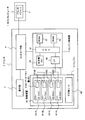
図1は、本発明を適用した画像形成装置であるプリンタの実施の形態例に係る構成図である。図1に示すプリンタ2が本発明を適用した画像形成装置であり、ホストコンピュータ1からの印刷要求等に基づいて、所定の印刷媒体に対して画像の形成を行なう装置である。かかるプリンタ2は、装着されているトナーカートリッジ611(現像ユニット)が品質が保証された品であるか否かを識別し、その結果に基づいて各トナーカートリッジ611に関する濃度調整を制御し、どの様なトナーカートリッジ611が装着されている場合にも適切な濃度調整制御が行えるようにしようとするものである。
FIG. 1 is a configuration diagram according to an embodiment of a printer which is an image forming apparatus to which the present invention is applied. A
図1に示すホストコンピュータ1は、プリンタ2に対して印刷要求を行なうホスト装置であり、ユーザ操作等に基づいて画像データと制御コマンドを含む印刷データをプリンタ2に送信する。なお、ホストコンピュータ1は、所謂パーソナルコンピュータなどで構成することができる。ホストコンピュータ1内のプリンタドライバ3は、ホストコンピュータ1内のアプリケーション(図示せず)などからのデータを受け取って、プリンタ2に送信する上記印刷データを生成する部分である。なお、プリンタドライバ3は、前記機能に関する処理をホストコンピュータ1に実行させるプログラムである。
A
図1に示すように、プリンタ2は、コントローラ部4、エンジン制御部5、エンジン6、及び操作部7などで構成される。コントローラ部4は、前記ホストコンピュータ1から送信される印刷データを受信し、当該データに含まれる制御コマンドを解釈すると共に、当該データに含まれる画像データに対して所定の処理を施してエンジン6側へ提供するデータを生成する。図示していないが、コントローラ部4には、CPUやメモリなどが備えられており、当該メモリには上記生成したデータなどが格納される。また、コントローラ部4は、プリンタ2の電源投入時、所定枚数の印刷処理が実施された時点、後述する感光体ドラム621が交換された時、あるいはトナーカートリッジ611が交換されたときなどに、エンジン制御部5に対して濃度調整処理の要求を行う。
As shown in FIG. 1, the
次に、エンジン制御部5は、図1に示されるように、CPU51(識別手段、制御手段)、ROM52、RAM53、本体側メモリ54、及びI/F55等で構成される。CPU51は、エンジン6の各部を制御する部分であるが、前述したコントローラ部4からの濃度調整要求を受けて濃度調整処理の制御も行い、この濃度調整制御に特徴がある。具体的な制御内容については後述する。
Next, as shown in FIG. 1, the
前記ROM52は、エンジン6を制御するための各種プログラムを記憶し、また、前記RAM53は、エンジン6に関する各種情報を一時的に記憶する。次に、本体側メモリ54は、後述する現像装置61の各トナーカートリッジ611に関する情報等を格納するデータ格納手段である。具体的には、現像装置61におけるトナーカートリッジ611の有無情報や後述するトナーカートリッジ側メモリ612に書き込まれたトナーの色情報、消費量情報等を格納する。
The
また、I/F55は、前記CPU51とトナーカートリッジ側メモリ612とのインターフェースであり、CPU51がトナーカートリッジ側メモリ612に書き込まれた前記情報を読み出して前記本体側メモリ54に書き込む際などに用いられる。
The I /
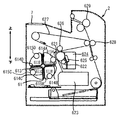
次に、エンジン6は、帯電ユニット、露光ユニット、現像装置、転写ユニット等で構成されるが、図1においては、現像装置61(現像手段)とその他ユニット62という区分で表現している。図2は、本プリンタ2のエンジン6部分の機構を中心に示した構成図である。
Next, the
感光体ドラム621は、円筒状の導電性基材とその外周面に形成された感光層を有し、中心軸に対して回転可能であり、矢印で示されるように時計方向に回転する。帯電ユニット622は、感光体ドラム621を帯電し、露光ユニット623は内蔵するレーザやLEDアレイなどの光源からのビームを帯電された感光体ドラム621に照射して静電気による潜像を形成する。露光ユニット623のビーム照射は、ホストコンピュータ1から入力される画像情報に基づいて変調された駆動信号により制御される。
The
現像装置61は、現像材であるトナーを収容するトナーカートリッジ611A〜611Dが着脱可能に装着される装着部614A〜614Dを有し、中心軸613に対して回転可能な現像ロータリーである。現像装置61を回転させて必要なトナーカートリッジ611A〜611Dを感光体ドラム621に近接させ、現像ローラ615A〜615Dに印加される現像バイアスにより、現像材を潜像が形成された感光体ドラム621に供給することで、潜像が現像材による像に現像される。
The developing
なお、現像装置61の装着部614A〜614Dには、ブラックK、シアンC、マゼンタM、イエローYの現像材をそれぞれ収容するトナーカートリッジ611A〜611Dを装着するなど、様々な色のトナーを組み合わせて装着することもできるが、本実施の形態例では、装着されている全てのトナーカートリッジ611A〜611DにブラックKのトナーが収容されているものとする。また、これらのトナーカートリッジ611A〜611Dは全て“品質が保証された品”のトナーカートリッジであるとは限らず、“製造元が品質を確認していない品”のトナーカートリッジが混在することもある。なお、トナーカートリッジ611A〜611Dなどに付されているA〜Dは、現像装置61におけるトナーカートリッジ611の装着位置を識別する記号である。
It should be noted that
一次転写ユニット626は、感光体621に形成されたトナー像を中間転写体627に転写する。中間転写体627は、例えばPETフィルムの表面にアルミ蒸着層を形成しその表面に半導電塗料を形成したエンドレスのベルトであり、感光体ドラム621と同じ周速度で回転駆動される。そして、二次転写ユニット628が、中間転写体627に形成されたトナー像を紙などの印刷媒体に転写し、定着ユニット629が、印刷媒体上に転写されたトナー像を媒体に溶着させて永久像とし、その印刷媒体はプリンタ2外に排出される。
The
クリーニングユニット624は、一次転写ユニット626と帯電ユニット622との間に設けられ、感光体ドラム621の表面に当接されるクリーニングブレード625を有し、一次転写された後に感光体ドラム621上に残存する現像材(トナー)がクリーニングブレード625により除去される。
The
また、装着されたトナーカートリッジ611の状態をプリンタ2が認識できるように、各トナーカートリッジ611には、現像材の色情報、残量情報等を記憶する記憶媒体、例えば非接触型不揮発性メモリ、であるトナーカートリッジ側メモリ612A〜612Dが設けられている。そして、電源が立ち上がった後や、トナーカートリッジ611が現像装置61に装着された後に、そのトナーカートリッジ側メモリ612の情報が読み出される。また、現像後にトナーカートリッジ611のトナーカートリッジ側メモリ612の残量情報が更新される。なお、このトナーカートリッジ側メモリ612には、そのトナーカートリッジ611の製造元やリサイクル回数などトナーカートリッジ611が品質が保証された品であるか否かを判断するための情報が含まれていても良い。
Each toner cartridge 611 has a storage medium for storing color information, remaining amount information, etc., such as a non-contact type nonvolatile memory, so that the
図1に示す操作部7は、ユーザがプリンタ2を操作するための部分であり、表示パネルや操作ボタン等で構成される。当該操作部7では、プリンタ2における印刷条件の設定など各種の設定行為が可能である。
An
以上説明したような構成を有する本実施の形態例に係るプリンタ2は、印刷時に、ホストコンピュータ1から所定の言語で記述された前記印刷データを供給され、感光体ドラム621への静電潜像の形成、対応するトナーカートリッジ611による現像、一次転写ユニット626による中間転写体627へのトナー像の転写を行なう。そして、さらに、二次転写ユニット628により紙などの印刷媒体に転写を行い、定着ユニット629により定着した後に、プリンタ2外に排出する。また、この印刷処理以外に、良好な画像濃度を保つために、所定のタイミングで濃度調整処理を行う。本プリンタ2では、この濃度調整制御に特徴があり、以下、この点について具体的に説明する。
The
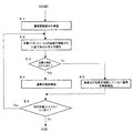
図3は、本プリンタ2が濃度調整処理を実行する際のCPU51が行う濃度調整制御の内容を例示したフローチャートである。まず、CPU51は、コントローラ部4が発する濃度調整要求を受信する(ステップS1)。かかる濃度調整要求は、前述のように、プリンタ2の電源投入時、所定枚数の印刷処理が実施された時点、感光体ドラム621が交換された時、あるいはトナーカートリッジ611が交換されたときなどに発せられる。
FIG. 3 is a flowchart illustrating the contents of density adjustment control performed by the
濃度調整要求を受けると、CPU51は、各トナーカートリッジ611A〜611Dに関して濃度調整処理の制御を開始し、まず、濃度調整の対象とするトナーカートリッジ611が品質が保証された品であるか否かを識別する(ステップS2)。この識別の処理は様々な方法で行うことができるが、例えば、前述したトナーカートリッジ側メモリ612にアクセスし、そこに記録された製造元の情報から品質が保証された品であるか否かを判断することができる。また、装着されているトナーカートリッジ611A〜611Dが品質が保証された品であるか否かの情報を事前に作成しておき、本体側メモリ54等にテーブル形式で記憶しておいてもよい。この場合には、CPU51がかかるテーブルにアクセスすることにより、容易に上記識別処理を行うことができる。なお、この事前に作成しておく品質が保証された品であるか否かの情報は、トナーカートリッジ611が交換された際などに、上記トナーカートリッジ側メモリ612に記憶された情報等からCPU51が判断して自動生成してもよいし、プリンタ2のユーザが品質が保証された品であるか否かを知っている場合には、操作部7やホストコンピュータ1での操作によってユーザが入力してもよい。
Upon receiving the density adjustment request, the
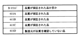
かかる識別処理の結果、対象のトナーカートリッジ611が品質が保証された品である場合には(ステップS3のYes)、CPU51は通常の濃度調整処理が行われるようにエンジン6の各部を制御する(ステップS4)。すなわち、品質が保証された品のトナーカートリッジ611に適した濃度調整が行われるように制御する。一方、対象のトナーカートリッジ611が製造元が品質を確認していない品である場合には(ステップS3のNo)、CPU51は製造元が品質を確認していない品用の濃度調整制御を実施する(ステップS5)。図4は、プリンタ2が装着しているトナーカートリッジ611が品質が保証された品であるか否かを例示した図である。図4に示す例の場合には、対象としているカートリッジが、トナーカートリッジ611A〜611Cであれば通常の濃度調整制御が行われ、トナーカートリッジ611Dであれば製造元が品質を確認していない品用の濃度調整制御が行われることになる。
As a result of such identification processing, if the target toner cartridge 611 is a product whose quality is guaranteed (Yes in step S3), the
かかる通常の、あるいは、製造元が品質を確認していない品用の濃度調整制御に基づいて濃度調整処理が実行されると、CPU51は、濃度調整を行うべき次のトナーカートリッジ611があるかをチェックし(ステップS6)、次の対象があれば(ステップS6のYes)、前記ステップS2からの処理を同様に行う。そして、次の対象がなくなれば(ステップS6のNo)、すなわち、今回の濃度調整要求に対して調整すべき全てのトナーカートリッジ611について処理が終了すると、一連の濃度調整制御を終了する。
When the density adjustment process is executed based on the density adjustment control for a product for which the quality is not confirmed by the manufacturer or the manufacturer, the
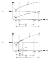
このように、本プリンタ2における濃度調整制御では、対象とするトナーカートリッジ611が品質が保証された品である場合と製造元が品質を確認していない品である場合とで制御を異にしており、この点が大きな特徴である。なお、通常の制御(ステップS4)によって行われる濃度調整処理の一例について以下に説明する。図5は、現像バイアスの調整について説明するための図である。図5に基づいて、濃度調整処理の一つである現像バイアスの調整について説明する。
As described above, in the density adjustment control in the
CPU51は、まず、複数の異なる現像バイアス値で、それぞれ、塗りつぶしのパッチを作像するように指示する。この指示に従って、エンジン6が動作し、調整対象のトナーカートリッジ611が感光体ドラム621に接近して、各現像バイアス値が印加されてトナー像が形成される。その後、形成された各パッチの濃度がセンサ(図示せず)によって計測される。
First, the
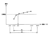
図5は、パッチが形成された各現像バイアス値と、計測された各パッチの濃度をプロット(図中の三角)したものである。この例では、通常の(品質が保証された品の)現像バイアスの調整範囲R1が−110V〜−330Vに設定されており、その範囲で、異なる6のバイアス値によるパッチ形成が行われている。 FIG. 5 is a plot (triangles in the figure) of the development bias values on which the patches are formed and the measured densities of the patches. In this example, the normal development bias adjustment range R1 (of a product whose quality is guaranteed) is set to -110V to -330V, and patches are formed with different bias values of 6 within that range. .
その後、CPU51は、上記得られた各パッチの現像バイアス値と濃度値の関係から、予め定められた目標値の濃度(図5の点線)になるような現像バイアスを求める。具体的には、図5に示すように、各パッチについてプロットされた点(図中の三角)間を線形補間し、それによって得られる現像バイアス−濃度曲線(正確には折線)から、目標濃度となる現像バイアス値(−XV)を求める。そして、求められた現像バイアス値になるように制御を行なう。なお、図5に示すR2は、本プリンタ2の現像バイアスについての許容調整範囲を示しており、この例では、−50V〜−400Vの範囲は調整が可能である。
Thereafter, the
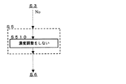
以上、通常(品質が保証された品)の濃度調整についてその一例を説明したが、一方、製造元が品質を確認していない品であった場合の制御(図3のステップS5)について以下に具体的に説明する。ここでは、3つの制御方法について述べるが、まず、第一の方法では、対象のトナーカートリッジ611が製造元が品質を確認していない品であった場合には、濃度調整を行わないという制御を行なう。図6は、かかる第一の方法を示したフローチャートである。図に示すように、この方法では、製造元が品質を確認していない品であると識別された場合には(ステップS3のNo)、単に、濃度調整処理を行わずに(ステップS510)当該トナーカートリッジ611についての濃度調整処理を終了し、次のトナーカートリッジ611へと処理が移行する(ステップS6)。このように、第一の方法では、どのように濃度調整を行えばよいか明らかでない製造元が品質を確認していない品のトナーカートリッジ611について濃度調整を行わないので、無理に通常(品質が保証された品用)の濃度調整を行ってしまいエラーが発生するなどの事態となることを避けることができる。 As described above, an example of the density adjustment of a normal product (a product whose quality is guaranteed) has been described. On the other hand, the control (step S5 in FIG. 3) when the manufacturer has not confirmed the quality is described below in detail. I will explain it. Here, three control methods will be described. First, in the first method, when the target toner cartridge 611 is a product whose quality has not been confirmed by the manufacturer, control is performed such that density adjustment is not performed. . FIG. 6 is a flowchart showing the first method. As shown in the figure, in this method, when it is identified that the manufacturer has not confirmed the quality (No in Step S3), the toner is simply not subjected to the density adjustment process (Step S510). The density adjustment process for the cartridge 611 is terminated, and the process proceeds to the next toner cartridge 611 (step S6). As described above, in the first method, since it is not clear how the density adjustment should be performed, the density adjustment is not performed for the toner cartridge 611 of a product whose quality is not confirmed by the manufacturer. It is possible to avoid the occurrence of an error or the like due to the density adjustment of the product.
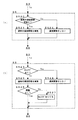
次に、図7は、製造元が品質を確認していない品であった場合の第二の制御方法を示したフローチャートである。第二の方法では、図7の(a)に示すように、まず、通常の濃度調整が可能であるか否かが判断される(ステップS520)。その結果、可能であると判断された場合には(ステップS520のYes)、通常(品質が保証された品用)の濃度調整を行うように制御し、濃度調整が実施される(ステップS521)。一方、不可能であると判断された場合には(ステップS520のNo)、濃度調整を行わないという制御を行なう(ステップS522)。 Next, FIG. 7 is a flowchart showing a second control method in the case where the manufacturer does not confirm the quality. In the second method, as shown in FIG. 7A, it is first determined whether or not normal density adjustment is possible (step S520). As a result, if it is determined that it is possible (Yes in step S520), control is performed so as to perform normal (for products with guaranteed quality) density adjustment, and density adjustment is performed (step S521). . On the other hand, if it is determined that it is not possible (No in step S520), control is performed not to perform density adjustment (step S522).
図8は、第二の方法を説明するための図である。図8は、図5と同様に、現像バイアスと濃度の関係を示した図であるが、例えば、調整対象としている製造元が品質を確認していない品のトナーカートリッジ611の特性が図中のaで示すような曲線で表される場合には、前述した通常の調整範囲R1内において、濃度が目標値となることがないので(図8のb部分を参照)、このような場合には、通常の濃度調整が不可能と判断されることになる。 FIG. 8 is a diagram for explaining the second method. FIG. 8 is a diagram showing the relationship between the developing bias and the density as in FIG. 5. For example, the characteristics of the toner cartridge 611 of the product whose quality is not confirmed by the manufacturer to be adjusted are shown in FIG. Since the density does not become the target value within the normal adjustment range R1 described above (see the part b in FIG. 8), in such a case, It will be judged that normal density adjustment is impossible.
また、図7の(b)は、当該第二の方法をより具体的に例示したフローチャートである。この例によれば、まず、対象としているトナーカートリッジ611に対してNGフラグなるものが立てられているか否かをチェックする(ステップS523)。このNGフラグは、通常の濃度調整が不可能であることを意味しており、該当する各トナーカートリッジ611に対して付加されるものである。そして、このNGフラグは、各トナーカートリッジ側メモリ612や本体側メモリ54に収められ、トナーカートリッジ611が交換された際などに消去される。
FIG. 7B is a flowchart illustrating the second method more specifically. According to this example, first, it is checked whether or not an NG flag is set for the target toner cartridge 611 (step S523). This NG flag means that normal density adjustment is impossible, and is added to each corresponding toner cartridge 611. The NG flag is stored in each toner cartridge side memory 612 and main
かかるチェックの結果、NGフラグがない場合には(ステップS523のNo)、通常の濃度調整を実施する(ステップS525)。そして、問題なく調整が実施されていれば(ステップS526のYes)、当該トナーカートリッジ611についての制御を終了し、エラーとなるなど調整が良好に行われなかった場合には(ステップS526のNo)、前述したNGフラグを当該トナーカートリッジ611に立てて(ステップS527)制御を終了する。一方、既にNGフラグが立っている場合には(ステップS523のYes)、濃度調整を実施しないで当該トナーカートリッジ611についての制御を終了する。 If the result of this check is that there is no NG flag (No in step S523), normal density adjustment is performed (step S525). If the adjustment is performed without any problem (Yes in step S526), the control on the toner cartridge 611 is terminated, and if the adjustment is not performed satisfactorily such as an error (No in step S526). Then, the above-mentioned NG flag is set in the toner cartridge 611 (step S527), and the control is terminated. On the other hand, if the NG flag is already set (Yes in step S523), the control for the toner cartridge 611 is terminated without performing the density adjustment.
このように、図7の(b)に示す例では、製造元が品質を確認していない品の場合にも1度は通常の濃度調整を試してみて通常の濃度調整が可能であるかを判断し、不可能である場合には、そのことをNGフラグで表現して、以降、このNGフラグに基づいて濃度調整を行なわない。 As described above, in the example shown in FIG. 7B, even if the manufacturer does not confirm the quality, the normal density adjustment is tried once to determine whether the normal density adjustment is possible. If this is not possible, this is expressed by an NG flag, and thereafter no density adjustment is performed based on this NG flag.
以上説明したように、第二の方法では、トナーカートリッジ611が製造元が品質を確認していない品であった場合にも、通常の濃度調整が可能であれば濃度調整を実施して良好な濃度での出力を実現でき、また、通常の濃度調整が不可能であるば濃度調整を行ってエラーとなる回数を減らすことができる。 As described above, in the second method, even when the toner cartridge 611 is a product whose quality has not been confirmed by the manufacturer, if the normal density adjustment is possible, the density adjustment is performed to obtain a good density. If the normal density adjustment is impossible, the density adjustment can be performed to reduce the number of errors.
次に、図9は、製造元が品質を確認していない品であった場合の第三の制御方法を示したフローチャートである。第三の方法では、図9の(a)に示すように、まず、対象のトナーカートリッジ611について通常の濃度調整であるか否かを問わず濃度調整が可能であるか否かをチェックする(ステップS530)。その結果、可能であると判断された場合には(ステップS530のYes)、濃度調整を実施する(ステップS531)。一方、不可能であると判断された場合には(ステップS530のNo)、濃度調整を行わないという制御を行なう(ステップS532)。すなわち、対象となっている製造元が品質を確認していない品について本プリンタ2において濃度調整が可能であれば実施し、可能でなければ実施しないという制御を行なう。ここで、濃度調整が可能であるか否かの判断は、様々な方法で行うことができるが、その判断の一例も含めて、図9の(b)に示すフローチャートに基づいて、第三の方法によるより具体的な処理例を説明する。
Next, FIG. 9 is a flowchart showing a third control method in the case where the manufacturer does not confirm the quality. In the third method, as shown in FIG. 9A, first, it is checked whether or not density adjustment is possible regardless of whether or not the target toner cartridge 611 is normal density adjustment ( Step S530). As a result, if it is determined that it is possible (Yes in step S530), density adjustment is performed (step S531). On the other hand, when it is determined that it is impossible (No in step S530), control is performed not to perform density adjustment (step S532). That is, control is performed such that if the density adjustment can be performed in the
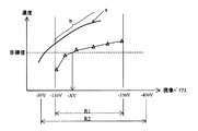
図9の(b)は、製造元が品質を確認していない品のトナーカートリッジ611について前述した現像バイアス値の調整を行おうとする場合の例であり、まず、可能な最も小さい現像バイアス値(正確には、絶対値が最小の現像バイアス値)での前記パッチの生成を行う(ステップS533)。図10は、図9の(b)に示す方法を説明するための図である。前記最小現像バイアス値でのパッチ生成は、図10に示す例では、前述したプリンタ2の許容調整範囲R2の最小値−50Vでパッチ生成を行うことを意味する。
FIG. 9B shows an example in which the above-described adjustment of the development bias value is attempted for the toner cartridge 611 whose quality has not been confirmed by the manufacturer. First, the smallest possible development bias value (accurate) is shown. In step S533, the patch is generated with the development bias value having the smallest absolute value. FIG. 10 is a diagram for explaining the method shown in FIG. In the example shown in FIG. 10, the patch generation with the minimum developing bias value means that the patch generation is performed with the minimum value −50 V of the allowable adjustment range R2 of the
次に、生成したパッチについて濃度を検出し(ステップS534)、その濃度に問題があるか否かをチェックする(ステップS535)。ここで問題があるか否かは、例えば、検出した濃度値が目標値よりも高いか否かで判断する。図10の(a)に示すように、この最小現像バイアス値で生成されたパッチについてcに示す位置にプロットされた場合には、すなわち、最小現像バイアス値での濃度が目標値よりも高い場合には、現像バイアスと濃度の関係が図のdに示す曲線のようになること、言い換えれば、現像バイアス値が許容調整範囲R2の間で濃度が目標値になることはないことが予想される。従って、このような場合には、本プリンタ2において良好な濃度値とするための現像バイアス値の調整が不可能であり、問題があると判断する。
Next, the density of the generated patch is detected (step S534), and it is checked whether there is a problem in the density (step S535). Whether there is a problem here is determined, for example, based on whether the detected density value is higher than the target value. As shown in FIG. 10A, when the patch generated with the minimum development bias value is plotted at the position shown in c, that is, when the density at the minimum development bias value is higher than the target value. Therefore, it is expected that the relationship between the developing bias and the density is as shown by a curve shown in FIG. 4D, in other words, the density does not become the target value when the developing bias value is within the allowable adjustment range R2. . Therefore, in such a case, it is determined that there is a problem because it is impossible to adjust the developing bias value to obtain a good density value in the
このように、検出された濃度値に問題があると判断された場合には(ステップS535のNo)、前述のように、適正な濃度調整ができないので濃度調整処理を実行しない(ステップS541)。一方、検出された濃度値に問題がないと判断された場合には(ステップS535のYes)、可能な最も大きい現像バイアス値(正確には、絶対値が最大の現像バイアス値)での前記パッチの生成を行う(ステップS536)。この最大現像バイアス値でのパッチ生成は、図10に示す例では、前述したプリンタ2の許容調整範囲R2の最大値−400Vでパッチ生成を行うことを意味する。
As described above, when it is determined that there is a problem with the detected density value (No in step S535), the density adjustment process is not executed because the appropriate density adjustment cannot be performed as described above (step S541). On the other hand, if it is determined that there is no problem with the detected density value (Yes in step S535), the patch with the largest possible development bias value (more precisely, the development bias value with the maximum absolute value) is used. Is generated (step S536). In the example shown in FIG. 10, the patch generation with the maximum developing bias value means that the patch generation is performed with the maximum value −400 V of the allowable adjustment range R2 of the
次に、生成したパッチについて濃度を検出し(ステップS537)、その濃度に問題があるか否かをチェックする(ステップS538)。ここで問題があるか否かは、例えば、検出した濃度値が目標値よりも低いか否かで判断する。図10の(a)に示すように、この最大現像バイアス値で生成されたパッチについてfに示す位置にプロットされた場合には、すなわち、最大現像バイアス値での濃度が目標値よりも低い場合には、前記ステップ535において最小現像バイアスでの濃度が目標値よりも低いと判断されているので(図10の(a)のe)、現像バイアスと濃度の関係が図のgに示す曲線のようになること、言い換えれば、現像バイアス値が許容調整範囲R2の間で濃度が目標値になることはないことが予想される。従って、このような場合には、本プリンタ2において良好な濃度値とするための現像バイアス値の調整が不可能であり、問題があると判断する。
Next, the density of the generated patch is detected (step S537), and it is checked whether there is a problem with the density (step S538). Here, whether there is a problem is determined by, for example, whether the detected density value is lower than the target value. As shown in FIG. 10A, when the patch generated at this maximum development bias value is plotted at the position indicated by f, that is, when the density at the maximum development bias value is lower than the target value. In step 535, since it is determined that the density at the minimum developing bias is lower than the target value (e in FIG. 10A), the relationship between the developing bias and the density is a curve shown in g of FIG. In other words, it is expected that the density does not become the target value when the development bias value is within the allowable adjustment range R2. Therefore, in such a case, it is determined that there is a problem because it is impossible to adjust the developing bias value to obtain a good density value in the
このように、検出された濃度値に問題があると判断された場合には(ステップS538のNo)、前述のように、適正な濃度調整ができないので濃度調整処理を実行しない(ステップS541)。一方、検出された濃度値に問題がないと判断された場合には(ステップS538のYes)、当該トナーカートリッジ611について濃度調整を行うべく、その調整範囲を決定する(ステップS539)。 As described above, when it is determined that there is a problem with the detected density value (No in step S538), as described above, the density adjustment process is not performed because appropriate density adjustment cannot be performed (step S541). On the other hand, if it is determined that there is no problem with the detected density value (Yes in step S538), an adjustment range is determined to perform density adjustment for the toner cartridge 611 (step S539).
図10の(b)には、前記ステップS538で問題なしと判断された場合の例を示しており、最小現像バイアス値で生成されたパッチについてはhに示す位置にプロットされ、最大現像バイアス値で生成されたパッチについてiに示す位置にプロットされている。従って、jで示す曲線のような特性が予想され、許容調整範囲R2の間で濃度が目標値になり得るので、このような場合には濃度調整を行う。そして、プロット点h及びiの位置関係から、例えば、図のR3で示す範囲が調整範囲として決定される。 FIG. 10B shows an example when it is determined that there is no problem in step S538. The patch generated with the minimum development bias value is plotted at the position indicated by h, and the maximum development bias value is shown. Is plotted at a position indicated by i. Therefore, a characteristic such as a curve indicated by j is expected, and the density can reach the target value within the allowable adjustment range R2. In such a case, density adjustment is performed. Then, for example, a range indicated by R3 in the figure is determined as the adjustment range from the positional relationship between the plot points h and i.
このように調整範囲が決定されると、その範囲内において、図5に基づいて説明した通常の調整と同様の手順で濃度調整処理が実施される(ステップS540)。図10の(b)に示す例では、各プロット点(図の三角)間が線形補間され、目標値の濃度を出すための現像バイアス−YVが導かれ、その値に設定される。 When the adjustment range is determined in this way, the density adjustment process is performed in the same procedure as in the normal adjustment described with reference to FIG. 5 (step S540). In the example shown in FIG. 10B, linear interpolation is performed between the plot points (triangles in the figure), and the developing bias -YV for obtaining the density of the target value is derived and set to that value.
このようにして、図9の(b)に示す方法では、本プリンタ2における現像バイアス値の調整が可能であるかをチェックし、可能な場合のみ適正な調整範囲において調整処理を実行する。
In this way, in the method shown in FIG. 9B, it is checked whether the development bias value in the
以上説明したように、第三の方法によれば、対象のトナーカートリッジ611が製造元が品質を確認していない品である場合に、通常の調整範囲を越えてプリンタ2の許容範囲で濃度調整の可能性がチェックされるので、製造元が品質を確認していない品であっても濃度調整が実行されて良好な濃度での画像出力ができる可能性がより高くなる。また、プリンタ2の許容範囲で濃度調整ができない場合には、濃度調整処理が実行されないので処理がエラーで中断するようなことを避けることができる。
As described above, according to the third method, when the target toner cartridge 611 is a product whose quality is not confirmed by the manufacturer, the density adjustment is performed within the allowable range of the
なお、前記第二の方法において、通常の濃度調整ができないと判断された場合(図7の(a)のステップS520のNo)に、直ぐに濃度調整を行わないと判断せずに、上記第三の方法を適用するようにしてもよい。すなわち、通常の濃度調整ができない場合に、調整範囲をプリンタ2の許容範囲まで広げて調整が可能であるか否かを判断し、その結果、可能であれば濃度調整処理を実施するようにする。これにより、製造元が品質を確認していない品の際に濃度調整がなされる機会が多くなる。
In the second method, when it is determined that the normal density adjustment cannot be performed (No in step S520 of FIG. 7A), the third method is performed without determining that the density adjustment is not performed immediately. The method may be applied. That is, when normal density adjustment cannot be performed, it is determined whether or not adjustment is possible by expanding the adjustment range to the allowable range of the
以上説明したように、本実施の形態例に係るプリンタ2では、濃度調整の際にトナーカートリッジ611が品質が保証された品であるか否かが考慮され、それぞれに適した制御がなされる。そして、製造元が品質を確認していない品である場合には、可能な限り濃度調整が実行されるように制御が行われる。従って、製造元が品質を確認していない品である場合にも適切に濃度調整が行われる可能性が高くなり、また、製造元が品質を確認していない品に対して誤った方法で濃度調整を実行してしまうこともなくなる。
As described above, in the
なお、前述の説明では濃度調整の具体例として現像バイアスの調整について述べたが、濃度調整の具体的な内容は他のものであってもよい。例えば、露光ユニット623における露光パワーの調整や濃度の階調補正などの濃度調整に関しても本発明を適用することができる。また、前記実施の形態例においては、複数の黒のトナーカートリッジ611を装着した装置として説明したが、CMYKの各トナーカートリッジを装着する場合や、一つの黒のトナーカートリッジを装着する場合においても、本発明を適用することができる。また、本実施の形態例では、各色毎に順番に印刷処理を行ういわゆる4サイクルの装置として説明したが、各色の処理を並行して行ういわゆるタンデム式の装置についても、本発明を適用することができる。
In the above description, the development bias adjustment is described as a specific example of the density adjustment, but the specific contents of the density adjustment may be other. For example, the present invention can be applied to density adjustment such as exposure power adjustment and density gradation correction in the
本発明の保護範囲は、上記の実施の形態に限定されず、特許請求の範囲に記載された発明とその均等物に及ぶものである。 The protection scope of the present invention is not limited to the above-described embodiment, but covers the invention described in the claims and equivalents thereof.
1 ホストコンピュータ、 2 プリンタ、 3 プリンタドライバ、 4 コントローラ部、 5 エンジン制御部、 6 エンジン、 7 操作部、 51 CPU(識別手段、制御手段)、 52 ROM、 53 RAM、 54 本体側メモリ、 55 I/F、 61 現像装置(現像手段)、 62 その他ユニット、 611 トナーカートリッジ(現像ユニット)、 612 トナーカートリッジ側メモリ
DESCRIPTION OF
Claims (4)
前記現像手段に装着された現像ユニットが、品質が保証された品であるか否かを識別する識別手段と、
前記トナー像の濃度を所定の目標値に調整するための濃度調整処理を制御する制御手段と、
を少なくとも備え、
前記制御手段は、前記濃度調整処理として、第1の濃度調整処理と、前記第1の濃度調整処理よりも濃度調整範囲が広い第2の濃度調整処理とを実行可能であり、
前記識別手段によって品質が保証された前記現像ユニットであると識別された場合には、前記第1の濃度調整処理を実行し、
前記識別手段によって品質が保証された前記現像ユニットでないと識別された場合には、前記第2の濃度調整処理を実行し、
さらに、前記第1の濃度調整処理を実行しても前記トナー像の濃度を所定の目標値に調整することができないと判断した場合には、該判断結果を画像形成装置または前記現像ユニットに備えられた記憶手段に記憶させる
ことを特徴とする画像形成装置。 Developing means for developing the electrostatic latent image on the image carrier to form a toner image;
Identification means for identifying whether or not the development unit mounted on the development means is a product whose quality is guaranteed;
Control means for controlling density adjustment processing for adjusting the density of the toner image to a predetermined target value;
Comprising at least
The control means can execute a first density adjustment process and a second density adjustment process having a wider density adjustment range than the first density adjustment process as the density adjustment process.
If the identification unit identifies the development unit assured in quality, the first density adjustment processing is executed,
If it is identified that the quality is not the developing unit whose quality is guaranteed by the identifying means, the second density adjustment processing is executed ,
Further, if it is determined that the density of the toner image cannot be adjusted to a predetermined target value even if the first density adjustment process is executed, the determination result is provided in the image forming apparatus or the developing unit. An image forming apparatus, wherein the image forming apparatus is stored in a storage unit .
前記トナー像の濃度を所定の目標値に調整するための濃度調整処理を制御する制御手段と、
を少なくとも備え、
前記制御手段は、前記濃度調整処理として、第1の濃度調整処理と、前記第1の濃度調整処理よりも濃度調整範囲が広い第2の濃度調整処理とを実行可能であり、
前記制御手段は、前記第1の濃度調整処理を実行しても前記トナー像の濃度を所定の目標値に調整することができないと判断した場合には、前記制御手段は、前記第2の濃度調整処理を実行し、
さらに、該判断結果を画像形成装置または前記現像ユニットに備えられた記憶手段に記憶させる
ことを特徴とする画像形成装置。 Developing means for developing the electrostatic latent image on the image carrier using toner contained in the mounted developing unit to form a toner image;
Control means for controlling density adjustment processing for adjusting the density of the toner image to a predetermined target value;
Comprising at least
The control means can execute a first density adjustment process and a second density adjustment process having a wider density adjustment range than the first density adjustment process as the density adjustment process.
If the control means determines that the density of the toner image cannot be adjusted to a predetermined target value even after executing the first density adjustment process, the control means Run the adjustment process ,
Further, the determination result is stored in a storage unit provided in the image forming apparatus or the developing unit .
ことを特徴とする請求項1または請求項2に記載の画像形成装置。 The second density adjustment process is executed based on density characteristics of the toner image obtained in correspondence with a minimum value and a maximum value of the density adjustment range with respect to the second density adjustment process. The image forming apparatus according to claim 1 or 2.
ことを特徴とする請求項1ないし請求項3のいずれか1つに記載の画像形成装置。 4. The density adjustment range according to claim 1, wherein the density adjustment range corresponds to a density adjustment factor selected from a group of development bias, exposure power, and gradation correction. Image forming apparatus.
Priority Applications (2)
| Application Number | Priority Date | Filing Date | Title |
|---|---|---|---|
| JP2004208239A JP4635496B2 (en) | 2004-07-15 | 2004-07-15 | Image forming apparatus |
| US11/182,054 US7317880B2 (en) | 2004-07-15 | 2005-07-15 | Image forming device for controlling density adjustment based on a type of development unit |
Applications Claiming Priority (1)
| Application Number | Priority Date | Filing Date | Title |
|---|---|---|---|
| JP2004208239A JP4635496B2 (en) | 2004-07-15 | 2004-07-15 | Image forming apparatus |
Publications (2)
| Publication Number | Publication Date |
|---|---|
| JP2006030514A JP2006030514A (en) | 2006-02-02 |
| JP4635496B2 true JP4635496B2 (en) | 2011-02-23 |
Family
ID=35599559
Family Applications (1)
| Application Number | Title | Priority Date | Filing Date |
|---|---|---|---|
| JP2004208239A Expired - Fee Related JP4635496B2 (en) | 2004-07-15 | 2004-07-15 | Image forming apparatus |
Country Status (2)
| Country | Link |
|---|---|
| US (1) | US7317880B2 (en) |
| JP (1) | JP4635496B2 (en) |
Families Citing this family (7)
| Publication number | Priority date | Publication date | Assignee | Title |
|---|---|---|---|---|
| JP4110003B2 (en) * | 2003-01-31 | 2008-07-02 | キヤノン株式会社 | Image forming apparatus |
| JP4960027B2 (en) * | 2006-06-23 | 2012-06-27 | 京セラドキュメントソリュ−ションズ株式会社 | Image forming apparatus |
| KR101249843B1 (en) * | 2007-08-10 | 2013-04-05 | 삼성전자주식회사 | Image forming apparatus and cartridge and control method of the image forming apparatus |
| JP5027641B2 (en) * | 2007-12-21 | 2012-09-19 | 京セラドキュメントソリューションズ株式会社 | Image forming apparatus |
| JP2013101194A (en) * | 2011-11-08 | 2013-05-23 | Sharp Corp | Image forming apparatus, system, printer driver, and method |
| JP6312756B2 (en) * | 2016-08-09 | 2018-04-18 | キヤノン株式会社 | Image forming apparatus, control method, and program |
| JP7467856B2 (en) * | 2019-09-27 | 2024-04-16 | ブラザー工業株式会社 | Image forming apparatus and consumable cartridge |
Family Cites Families (9)
| Publication number | Priority date | Publication date | Assignee | Title |
|---|---|---|---|---|
| JPH05224479A (en) * | 1992-02-10 | 1993-09-03 | Toshiba Corp | Image forming device |
| JP2000131900A (en) * | 1998-10-28 | 2000-05-12 | Canon Inc | Concentration control device and method |
| US6658219B1 (en) * | 1999-09-30 | 2003-12-02 | Fuji Photo Film Co., Ltd. | Method, device, system and recording medium for detecting improper cartridge, and cartridge |
| JP2002023444A (en) * | 2000-07-07 | 2002-01-23 | Canon Inc | Image forming apparatus, control method for image forming apparatus, and storage medium |
| JP2002251047A (en) * | 2001-02-23 | 2002-09-06 | Seiko Epson Corp | Image forming apparatus and image forming method |
| JP2003195705A (en) * | 2001-12-28 | 2003-07-09 | Murata Mach Ltd | Image forming apparatus |
| JP2003345180A (en) | 2002-05-23 | 2003-12-03 | Ricoh Co Ltd | Image forming device |
| US7330672B2 (en) * | 2004-05-17 | 2008-02-12 | Fuji Xerox Co., Ltd. | Image forming apparatus able to execute selected operating mode upon replacement of replaceable unit, and method therefore |
| JP4650781B2 (en) * | 2004-05-17 | 2011-03-16 | 富士ゼロックス株式会社 | Image forming apparatus equipped with an exchange unit |
-
2004
- 2004-07-15 JP JP2004208239A patent/JP4635496B2/en not_active Expired - Fee Related
-
2005
- 2005-07-15 US US11/182,054 patent/US7317880B2/en not_active Expired - Fee Related
Also Published As
| Publication number | Publication date |
|---|---|
| JP2006030514A (en) | 2006-02-02 |
| US7317880B2 (en) | 2008-01-08 |
| US20060013599A1 (en) | 2006-01-19 |
Similar Documents
| Publication | Publication Date | Title |
|---|---|---|
| JP5257602B2 (en) | Image forming apparatus, image forming method, program, and recording medium | |
| JP4635496B2 (en) | Image forming apparatus | |
| JP2002221833A (en) | Image forming apparatus and cartridge | |
| JP4461906B2 (en) | Image forming apparatus that performs calibration without reducing printing throughput | |
| US7860413B2 (en) | Image forming apparatus and method therefor as well as program and storage medium thereof | |
| JP3888069B2 (en) | Image forming apparatus and image forming method | |
| JP2001147620A (en) | Electrophotographic image forming apparatus and cartridge | |
| JP4239966B2 (en) | Image forming apparatus | |
| JP2005091767A (en) | Image forming apparatus | |
| US7233749B2 (en) | Image forming device for performing calibration by patch pattern | |
| JP2007010745A (en) | Image forming apparatus and registration adjusting method in the apparatus | |
| JP2007264371A (en) | Image forming apparatus and image forming density adjusting method | |
| JPH10105021A (en) | Process cartridge, image forming apparatus, and image adjustment control method for image forming apparatus | |
| JP2005246723A (en) | Image forming apparatus and driver program | |
| JP7151212B2 (en) | image forming device | |
| JP4682537B2 (en) | Image forming apparatus, image forming system, and program for image forming apparatus | |
| JP2008151855A (en) | Image forming apparatus and image forming method | |
| JP4576990B2 (en) | Image forming apparatus | |
| US9423753B1 (en) | Image forming apparatus | |
| JP2005352409A (en) | Image forming apparatus | |
| JP2006003498A (en) | Image forming apparatus and driver program | |
| JP2025139874A (en) | Image formation control method and image forming apparatus | |
| JP2005292771A (en) | Image forming apparatus | |
| JP4736421B2 (en) | Image forming apparatus | |
| JP2025173148A (en) | Image forming apparatus |
Legal Events
| Date | Code | Title | Description |
|---|---|---|---|
| A621 | Written request for application examination |
Free format text: JAPANESE INTERMEDIATE CODE: A621 Effective date: 20070703 |
|
| RD04 | Notification of resignation of power of attorney |
Free format text: JAPANESE INTERMEDIATE CODE: A7424 Effective date: 20090625 |
|
| RD03 | Notification of appointment of power of attorney |
Free format text: JAPANESE INTERMEDIATE CODE: A7423 Effective date: 20090706 |
|
| A977 | Report on retrieval |
Free format text: JAPANESE INTERMEDIATE CODE: A971007 Effective date: 20100326 |
|
| A131 | Notification of reasons for refusal |
Free format text: JAPANESE INTERMEDIATE CODE: A131 Effective date: 20100406 |
|
| A521 | Request for written amendment filed |
Free format text: JAPANESE INTERMEDIATE CODE: A523 Effective date: 20100517 |
|
| A131 | Notification of reasons for refusal |
Free format text: JAPANESE INTERMEDIATE CODE: A131 Effective date: 20100803 |
|
| A521 | Request for written amendment filed |
Free format text: JAPANESE INTERMEDIATE CODE: A523 Effective date: 20100914 |
|
| TRDD | Decision of grant or rejection written | ||
| A01 | Written decision to grant a patent or to grant a registration (utility model) |
Free format text: JAPANESE INTERMEDIATE CODE: A01 Effective date: 20101026 |
|
| A01 | Written decision to grant a patent or to grant a registration (utility model) |
Free format text: JAPANESE INTERMEDIATE CODE: A01 |
|
| A61 | First payment of annual fees (during grant procedure) |
Free format text: JAPANESE INTERMEDIATE CODE: A61 Effective date: 20101108 |
|
| FPAY | Renewal fee payment (event date is renewal date of database) |
Free format text: PAYMENT UNTIL: 20131203 Year of fee payment: 3 |
|
| R150 | Certificate of patent or registration of utility model |
Ref document number: 4635496 Country of ref document: JP Free format text: JAPANESE INTERMEDIATE CODE: R150 Free format text: JAPANESE INTERMEDIATE CODE: R150 |
|
| S531 | Written request for registration of change of domicile |
Free format text: JAPANESE INTERMEDIATE CODE: R313532 |
|
| R350 | Written notification of registration of transfer |
Free format text: JAPANESE INTERMEDIATE CODE: R350 |
|
| LAPS | Cancellation because of no payment of annual fees |