JP4461906B2 - Image forming apparatus that performs calibration without reducing printing throughput - Google Patents
Image forming apparatus that performs calibration without reducing printing throughput Download PDFInfo
- Publication number
- JP4461906B2 JP4461906B2 JP2004150451A JP2004150451A JP4461906B2 JP 4461906 B2 JP4461906 B2 JP 4461906B2 JP 2004150451 A JP2004150451 A JP 2004150451A JP 2004150451 A JP2004150451 A JP 2004150451A JP 4461906 B2 JP4461906 B2 JP 4461906B2
- Authority
- JP
- Japan
- Prior art keywords
- unit
- calibration
- developing unit
- developing
- printing
- Prior art date
- Legal status (The legal status is an assumption and is not a legal conclusion. Google has not performed a legal analysis and makes no representation as to the accuracy of the status listed.)
- Expired - Fee Related
Links
Images


Classifications
-
- G—PHYSICS
- G03—PHOTOGRAPHY; CINEMATOGRAPHY; ANALOGOUS TECHNIQUES USING WAVES OTHER THAN OPTICAL WAVES; ELECTROGRAPHY; HOLOGRAPHY
- G03G—ELECTROGRAPHY; ELECTROPHOTOGRAPHY; MAGNETOGRAPHY
- G03G15/00—Apparatus for electrographic processes using a charge pattern
- G03G15/55—Self-diagnostics; Malfunction or lifetime display
- G03G15/553—Monitoring or warning means for exhaustion or lifetime end of consumables, e.g. indication of insufficient copy sheet quantity for a job
- G03G15/556—Monitoring or warning means for exhaustion or lifetime end of consumables, e.g. indication of insufficient copy sheet quantity for a job for toner consumption, e.g. pixel counting, toner coverage detection or toner density measurement
-
- G—PHYSICS
- G03—PHOTOGRAPHY; CINEMATOGRAPHY; ANALOGOUS TECHNIQUES USING WAVES OTHER THAN OPTICAL WAVES; ELECTROGRAPHY; HOLOGRAPHY
- G03G—ELECTROGRAPHY; ELECTROPHOTOGRAPHY; MAGNETOGRAPHY
- G03G2215/00—Apparatus for electrophotographic processes
- G03G2215/00362—Apparatus for electrophotographic processes relating to the copy medium handling
- G03G2215/00535—Stable handling of copy medium
- G03G2215/00717—Detection of physical properties
- G03G2215/00729—Detection of physical properties of sheet amount in input tray
-
- G—PHYSICS
- G03—PHOTOGRAPHY; CINEMATOGRAPHY; ANALOGOUS TECHNIQUES USING WAVES OTHER THAN OPTICAL WAVES; ELECTROGRAPHY; HOLOGRAPHY
- G03G—ELECTROGRAPHY; ELECTROPHOTOGRAPHY; MAGNETOGRAPHY
- G03G2215/00—Apparatus for electrophotographic processes
- G03G2215/01—Apparatus for electrophotographic processes for producing multicoloured copies
- G03G2215/0103—Plural electrographic recording members
- G03G2215/0109—Single transfer point used by plural recording members
- G03G2215/0116—Rotating set of recording members
Landscapes
- Physics & Mathematics (AREA)
- General Physics & Mathematics (AREA)
- Control Or Security For Electrophotography (AREA)
- Color Electrophotography (AREA)
- Dry Development In Electrophotography (AREA)
Description
本発明は、電子印刷技術を用いて画像を形成する画像形成装置に関し、特に、同色の現像剤を収納する複数の現像ユニットを有し、印刷のスループットを低下させずにパッチパターンによるキャリブレーションを行う画像形成装置に関する。 The present invention relates to an image forming apparatus that forms an image using an electronic printing technique, and in particular, has a plurality of developing units that store developers of the same color, and performs calibration with a patch pattern without reducing printing throughput. The present invention relates to an image forming apparatus.
電子写真技術を用いて画像を形成する画像形成装置は、プリンタ、ファクシミリ、複写機などに設けられ、画像データに応じて静電潜像が形成される像担持体(感光体ドラム)と、像担持体の外周面を帯電させる帯電ユニットと、帯電された像担持体の外周面を画像データに応じて露光して静電潜像を形成する露光ユニットと、像担持体に現像剤であるトナーを供給して像担持体の静電潜像をトナー像に現像する現像装置と、トナー像を転写対象の媒体に転写させる転写ユニットとを有する。現像装置は、複数のカラートナーまたは同色のトナーを収容する現像ユニットを着脱可能に保持し、現像タイミングに対応して適切な現像ユニットを像担持体に近接させる。そのために現像装置は、回転制御される現像ロータリーを有する。カラー印刷を行うときは、複数色のカラートナー、例えば4色(イエローY、マゼンタM、シアンC、ブラックK)の現像ユニットが現像ロータリーに装着され、それらの現像ユニットが順次像担持体に近接され、各色の現像が行われる。 An image forming apparatus that forms an image using electrophotographic technology is provided in a printer, a facsimile machine, a copying machine, etc., and an image carrier (photosensitive drum) on which an electrostatic latent image is formed according to image data, and an image A charging unit that charges the outer peripheral surface of the carrier, an exposure unit that exposes the outer peripheral surface of the charged image carrier according to image data to form an electrostatic latent image, and a toner that is a developer on the image carrier And a developing device that develops the electrostatic latent image on the image carrier into a toner image, and a transfer unit that transfers the toner image to a transfer target medium. The developing device detachably holds a developing unit containing a plurality of color toners or toners of the same color, and brings an appropriate developing unit close to the image carrier corresponding to the development timing. For this purpose, the developing device has a developing rotary whose rotation is controlled. When performing color printing, a plurality of color toners, for example, four color (yellow Y, magenta M, cyan C, black K) developing units are mounted on the developing rotary, and these developing units sequentially approach the image carrier. Then, development of each color is performed.
一方、現像装置の現像ロータリーに、同じ色、例えばブラック、の現像ユニットを複数個同時に装着し、モノクロ印刷専用の画像形成装置とすることが提案されている。例えば、特許文献1、2に示される通りである。このモノクロ専用の画像形成装置は、複数のブラックの現像ユニットが装着可能であるため、大量のモノクロ印刷を行う場合でも、複数の現像ユニットを順次使用することで、現像ユニットの交換頻度を少なくすることができる。 On the other hand, it has been proposed that a plurality of developing units of the same color, for example, black, be simultaneously mounted on the developing rotary of the developing device to provide an image forming apparatus dedicated to monochrome printing. For example, as shown in Patent Documents 1 and 2. Since this monochrome-dedicated image forming apparatus can be equipped with a plurality of black development units, even when a large amount of monochrome printing is performed, the development units can be replaced less frequently by sequentially using the plurality of development units. be able to.
電子写真技術を利用した画像形成装置では、像担持体(感光体ドラム)を所定バイアス電位に帯電し、所定の強度の露光ビームを照射して潜像を形成し、現像ユニットと像担持体とのバイアス電圧差により現像ユニットからトナーを付着させる。従って、現像ユニットと像担持体との間のバイアス電圧や露光強度などの制御パラメータに応じて、トナーの付着状態が異なる。また、同じ制御パラメータでも外部環境の変化、現像ユニットの使用回数の増大、現像ユニットの交換などに伴って、トナーの付着状態が異なる。そして、かかるトナー付着状態は、現像パターンの濃度に影響する。そこで、一般に、像担持体上にトナーによる所定のパッチパターンを形成し、そのパッチパターンの光学濃度に応じて、最適な制御パラメータを決定するキャリブレーションが適宜行われる。
現像ユニットによる印刷枚数の増大に伴い、帯電履歴によりトナーの状態が変化し、上記のパッチパターンを利用したキャリブレーションが必要になる。そこで、通常は、所定の印刷枚数だけ使用された現像ユニットに対しては、キャリブレーション動作を実行して、制御パラメータを適正値に更新することが行われる。しかしながら、かかるキャリブレーション動作は、露光、現像、パッチパターンの光学濃度の検出など一定の工数と時間を要するので、ユーザから要求される印刷要求の途中に実行されると、印刷が中断され、印刷スループットの低下を招く。 As the number of printed sheets by the developing unit increases, the toner state changes depending on the charging history, and calibration using the patch pattern is required. Therefore, normally, a calibration operation is executed for a development unit that has been used for a predetermined number of printed sheets, and the control parameter is updated to an appropriate value. However, this calibration operation requires a certain amount of man-hours and time such as exposure, development, and detection of the optical density of the patch pattern. Therefore, if it is executed in the middle of a print request requested by the user, printing is interrupted and printing is performed. The throughput is reduced.
そこで、本発明の目的は、印刷スループットの低下を回避して、パッチパターンによるキャリブレーションを行う画像形成装置を提供することにある。 SUMMARY OF THE INVENTION An object of the present invention is to provide an image forming apparatus that performs calibration using a patch pattern while avoiding a decrease in printing throughput.
上記の目的を達成するために、本発明の第1の側面によれば、画像形成装置は、潜像が形成される像担持体と、同色の現像剤を収納する複数の現像ユニットが着脱自在に装着される現像装置と、印刷要求に応答して像担持体の潜像に現像ユニットの現像剤を付着させて現像を行う印刷動作を制御する制御手段とを有する。そして、画像形成装置の制御手段は、印刷要求を実行すると使用中の第1の現像ユニットがキャリブレーションタイミングに達する場合に、キャリブレーションタイミングに達しない第2の現像ユニットが存在する場合は当該第2の現像ユニットを使用して印刷動作を実行し、キャリブレーションタイミングに達しない第2の現像ユニットが存在しない場合は、印刷要求枚数が所定閾値を超えない場合に第1の現像ユニットを使用して印刷動作を実行し、所定閾値を超える場合にキャリブレーション動作を実行しその後印刷動作を実行する。可能な限りキャリブレーションを回避して複数の現像ユニットのいずれかを使用して印刷要求の印刷動作を実行することで、キャリブレーションによる印刷の中断をできるだけ避けて印刷のスループットを上げることができる。 In order to achieve the above object, according to a first aspect of the present invention, an image forming apparatus is detachably attachable to an image carrier on which a latent image is formed and a plurality of developing units containing the same color developer. And a control unit that controls a printing operation in which development is performed by attaching the developer of the developing unit to the latent image of the image carrier in response to a print request. Then, the control unit of the image forming apparatus, when the first developing unit in use to execute the print requests is reached in the calibration timing, when the second developing unit does not reach the calibration timing exists the When the printing operation is executed using the second developing unit and there is no second developing unit that does not reach the calibration timing , the first developing unit is used when the requested number of prints does not exceed the predetermined threshold. The printing operation is executed, and when the predetermined threshold value is exceeded, the calibration operation is executed, and then the printing operation is executed. By avoiding calibration as much as possible and using any one of a plurality of development units to execute a print operation for a print request, it is possible to avoid printing interruption due to calibration as much as possible and increase printing throughput.
上記の第1の側面において、より好ましい実施例では、キャリブレーションタイミングに達しない第2の現像ユニットが存在する場合でも、印刷要求枚数が所定閾値を超えない場合には使用中の第1の現像ユニットを使用して印刷動作を実行し、所定閾値を超える場合には上記の通り第2の現像ユニットを使用して印刷動作を実行する。第2の現像ユニットが使用可能であっても、印刷枚数が少ない場合は、現像ユニットの切換を行わずに第1の現像ユニットで印刷動作を行うことにより、現像ユニットの切換に伴う時間を節約することができ、印刷スループットを上げることができる。 In the first aspect described above, in a more preferred embodiment, even when there is a second developing unit that does not reach the calibration timing, the first development in use is performed if the requested number of prints does not exceed a predetermined threshold. The printing operation is executed using the unit, and when the predetermined threshold value is exceeded, the printing operation is executed using the second developing unit as described above. Even if the second development unit can be used, if the number of printed sheets is small, the printing operation is performed with the first development unit without switching the development unit, thereby saving the time required for switching the development unit. Printing throughput can be increased.
上記の目的を達成するために、本発明の第2の側面は、潜像が形成される像担持体と、同色の現像剤を収納する複数の現像ユニットが着脱自在に装着される現像装置と、印刷要求に応答して前記像担持体の潜像に前記現像ユニットの現像剤を付着させて現像を行う印刷動作と、前記像担持体にパッチパターンを現像してキャリブレーションを行うキャリブレーション動作とを制御する制御手段とを有し、
前記制御手段は、前記印刷要求の印刷動作を実行すると使用中の第1の現像ユニットのキャリブレーションタイミングに達する場合に、
キャリブレーションタイミングに達しない第2の現像ユニットが存在する場合は、当該第2の現像ユニットを使用して印刷動作を実行し、
前記キャリブレーションタイミングに達しない第2の現像ユニットが存在しない場合は、印刷要求枚数が所定閾値を超えない場合に前記第1の現像ユニットを使用して印刷動作を実行し、前記所定閾値を超える場合に前記キャリブレーション動作を実行しその後印刷動作を実行することを特徴とする画像形成装置である。
In order to achieve the above object, according to a second aspect of the present invention, there is provided an image carrier on which a latent image is formed, and a developing device in which a plurality of developing units containing the same color developer are detachably mounted. A printing operation in which the developer of the developing unit is attached to the latent image of the image carrier in response to a print request and development is performed, and a calibration operation in which a patch pattern is developed on the image carrier to perform calibration And control means for controlling
When the control means, is reached in the calibration timing of the first developing unit in use and to perform the printing operation of the print request,
If there is a second developing unit that does not reach the calibration timing, a printing operation is executed using the second developing unit,
If there is no second developing unit that does not reach the calibration timing, a printing operation is executed using the first developing unit when the requested number of prints does not exceed a predetermined threshold, and the predetermined threshold is exceeded. In this case, the image forming apparatus is characterized in that the calibration operation is executed and then the printing operation is executed.
上記第2の側面において、好ましい実施例では、前記制御手段は、前記キャリブレーションタイミングに達しない第2の現像ユニットが存在する場合でも、前記印刷要求枚数が所定閾値を超えない場合は前記第1の現像ユニットを使用して印刷動作を実行し、前記所定閾値を超える場合は当該第2の現像ユニットを使用して印刷動作を実行することを特徴とする。 In the second aspect described above, in a preferred embodiment, the control unit includes the first control unit when the requested number of prints does not exceed a predetermined threshold even when there is a second developing unit that does not reach the calibration timing . The developing operation is performed using the second developing unit, and when the predetermined threshold is exceeded, the printing operation is performed using the second developing unit.
以下、図面にしたがって本発明の実施の形態について説明する。但し、本発明の技術的範囲はこれらの実施の形態に限定されず、特許請求の範囲に記載された事項とその均等物まで及ぶものである。 Hereinafter, embodiments of the present invention will be described with reference to the drawings. However, the technical scope of the present invention is not limited to these embodiments, but extends to the matters described in the claims and equivalents thereof.
図1は、本実施の形態における画像形成装置の主要構成図である。本実施の形態では、画像形成装置としてレーザービームプリンタ10を例にして説明する。図1のプリンタ10は、モノクロ印刷モード時の構成を示す。
FIG. 1 is a main configuration diagram of an image forming apparatus according to the present embodiment. In the present embodiment, a
プリンタ10は、潜像を担持する像担持体である感光体ドラム20の回転方向に沿って、帯電ユニット30と、露光ユニット40と、現像装置50と、一次転写ユニット60と、中間転写体70と、クリーニングユニット75とを有する。さらに、プリンタ10は、二次転写ユニット80と、定着ユニット90と、ユーザへの種々の情報を出力する表示ユニット95と、これらのユニットを制御する制御ユニット100とを有する。
The
感光体ドラム20は、円筒状の導電性基材とその外周面に形成された感光層を有し、中心軸に対して回転可能であり、矢印で示されるように時計方向に回転する。帯電ユニット30は、感光体ドラム20の外周面を一様に帯電し、露光ユニット40は、内蔵するレーザやLEDアレイなどの光源のビームを帯電した感光体ドラム20に照射して、静電気による潜像を形成する。露光ユニット40のビーム照射は、ホストコンピュータから入力される画像情報に基づいて変調された駆動信号により制御される。
The
現像装置50は、中心軸50eに対して回転可能な現像ロータリーであり、その装着部50a〜50dに現像剤であるトナーを収容する現像ユニット51〜54が着脱可能に装着される。現像装置50を回転させて必要な現像ユニット51〜54を感光体ドラム20に近接させ、帯電した現像剤を感光体ドラム20に現像ユニットと感光体ドラム間のバイアス電圧によって供給することで、潜像が現像剤による像に現像される。
The developing
図1の例では、現像装置50の装着部50a〜50dには、全てブラックKの現像剤を収容する現像ユニット51〜54が装着され、モノクロ印刷モードにされている。モノクロ印刷プロセスでは、4つの現像ユニットのうちいずれかの現像ユニットの現像剤を使用して現像が行われる。また、現像装置50の装着部50a〜50dに、ブラックK、シアンC、マゼンタM、及びイエローYの現像剤をそれぞれ収容する現像ユニットが装着されると、カラー印刷モードにされる。カラー印刷プロセスでは、CMYKの順番で感光体ドラム20への潜像の形成とそれぞれの現像剤による現像とが行われる。したがって、現像装置50は、各色の潜像形成と現像プロセス毎に、時計方向に回転して適切な色の現像ユニットを感光体ドラム20に近接させ、順次現像を行う。
In the example of FIG. 1, the developing
一次転写ユニット60は、感光体20に形成されたトナー像を中間転写体70に転写する。中間転写体70は、例えばPETフィルムの表面にアルミ蒸着層を形成しその表面に半導電塗料を形成したエンドレスのベルトであり、感光体ドラム20と同じ周速度で回転駆動される。カラー印刷モードでは、中間転写体70にCMYKそれぞれの画像が重ねて転写され、モノクロ印刷モードでは、中間転写体70に単色の画像が転写される。そして、二次転写ユニット80が、中間転写体70に形成されたトナー像を紙などの印刷媒体に転写し、定着ユニット90が、印刷媒体上に転写されたトナー像を媒体に溶着させて永久像とし、その印刷媒体はプリンタの外に排出される。
The
クリーニングユニット75は、一次転写ユニット60と帯電ユニット30との間に設けられ、感光体ドラム20の表面に常時当接されるクリーニングブレード76を有し、一次転写された後に感光体ドラム20上に残存する現像剤(トナー)がクリーニングブレード76により除去される。クリーニングブレード76を有するクリーニングユニット75には、除去された現像剤が蓄積される。
The
各現像ユニット51〜54は、現像装置50に着脱可能であり、装着された現像ユニットの状態をプリンタが認識できるように、現像ユニットには、現像剤の色情報、残量情報、過去の印刷枚数などの情報を記憶する記憶媒体、例えば非接触型不揮発性メモリが設けられている。そして、電源が立ち上がった後や、現像ユニットが現像装置に装着された後に、その現像ユニットの不揮発性メモリの情報が読み出される。また、現像後に現像ユニットの不揮発性メモリに現像剤の残量情報や印刷枚数などの情報が更新される。
Each of the developing
図1に示されるように、現像装置50の全ての装着位置にブラック用の現像ユニット51〜54が装着されると、4つの現像ユニットの不揮発性メモリから色情報が読み出され、制御ユニット100によりモノクロ印刷モードと判定される。また、現像装置50の装着位置にCMYKの現像ユニットが装着されると、同様に4つの現像ユニットの不揮発性メモリから色情報が読み出され、制御ユニット100によりカラー印刷モードと判定される。そして、いずれの印刷モードでも、印刷が実行されるとその時に使用した現像剤量が求められ、その使用した現像剤量に基づいて、それぞれの現像ユニットのトナー残量情報が更新され各不揮発性メモリに維持される。
As shown in FIG. 1, when the
図2は、現像装置50の詳細な構造を示す断面図である。現像装置50は、複数の現像ユニット51〜54を、ハウジング50fと中心軸50eを中心に回転する装着部50aとの間のスペースに、それぞれ着脱可能に装着する。複数の現像ユニットは全て同じ構造を有し、例えば現像ユニット51は、容器51aと、現像ローラ51bと、供給ローラ51cと、仕切り板51dとを備える。現像ローラ51bと供給ローラ51cとは、容器51aに対して回転可能に取り付けられ、現像ユニットが感光体ドラム20の近接した時に、図示しないモータによりそれぞれ回転する。供給ローラ51cは現像ローラbに圧接して回転することで、その周囲のトナーを摩耗帯電させ、帯電したトナーが現像ローラbを介して感光体ドラム20に供給される。仕切り板51dは、供給ローラ51cを囲むように設けられ、容器51c内のトナー収容空間を左右に仕切っている。この仕切り板51dを設けることで、供給ローラ51c側の空間内のトナーが当該供給ローラ51cと現像ローラ51bとの圧接回転により現像ローラ51b側に供給される。また、現像装置50が矢印で示されるように半時計回り方向に90度ずつ回転して180度回転すると、現像ユニット53の位置になり、供給ローラ51c側の収納空間内のトナーが仕切り板51cの上部で供給ローラ51cとは反対側の収納空間のトナーと混合され、更に90度回転することで混合したトナーが撹拌されてリフレッシュされる。更に90度回転すると、その撹拌されてリフレッシュされたトナーの一部が、供給ローラ51c側の収納空間内に収納される。このように、仕切り板51を設けてトナー収納空間を分割し、その一方のトナー収納空間内に供給ローラを設けているので、現像装置50の回転により、摩擦帯電されたトナーが撹拌されリフレッシュされる。
FIG. 2 is a cross-sectional view showing a detailed structure of the developing
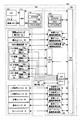
図3は、本実施の形態における制御ユニット100の構成図である。制御手段としての制御ユニット100は、ホストコンピュータから印刷ジョブデータを供給され所定の画像処理を行い、エンジンへの制御信号と画像信号を生成すると共に、表示パネル95に対する表示制御を行うメインコントローラ101と、印刷エンジンの各ユニットを制御するエンジンコントローラ102とを有する。メインコントローラ101は、ホストコンピュータからの印刷ジョブデータを受信するインターフェース112と、印刷ジョブデータ内の画像データを格納する画像メモリ113と、ハーフトーン処理などの画像処理と表示モードの設定、自動判別、表示パネルの表示制御などを行うCPU111と、不揮発性メモリ114aとRAM,ROM114bとを有するメモリユニット114とを有する。不揮発性メモリ114aには、プリンタがカラー印刷モードか、モノクロ印刷モードかを示す印刷モード情報が格納される。印刷モードは、電源オン時に現像装置に装着された現像ユニットのメモリからの色情報に応じてメインコントローラ101により判定され、判定された印刷モード情報が不揮発性メモリ114aに書き込まれる。
FIG. 3 is a configuration diagram of the
また、エンジンコントローラ102は、CPU120に加えて、メモリユニット116と、シリアルインターフェース121と、入出力ポート123と、帯電ユニット30、露光ユニット40、現像装置50をそれぞれ駆動する駆動制御回路124,125,126と、一次転写ユニット60、二次転写ユニット80、定着ユニット90、表示ユニット95、クリーニングユニット75をそれぞれ駆動する駆動制御回路群128とを有する。また、現像装置50のホームポジションを検出する検出部31が設けられる。エンジンコントローラ102は、メインコントローラ101から印刷プロセスを制御する制御信号と露光ビームの照射を制御する画像信号とを供給され、各ユニットの制御を行う。
In addition to the
また、現像装置50に装着される現像ユニット51〜54は、それぞれ現像ユニット側メモリ51a〜54aを有する。これらのメモリは、例えばFeRAMやEEPROMなどの不揮発性メモリで構成され、現像剤の色情報、現像剤の残量情報、現像ユニットのID情報、現像ユニットによる過去の印刷枚数などの情報を格納する。電源オン時や現像ユニットを交換または追加装着した時に、エンジンコントローラ102がこれらの現像ユニット側メモリ51a〜54aにアクセスし、現像ユニットの装着の有無、色情報、ID情報、現像剤の残量情報、過去の印刷枚数情報などを読み取る。また、現像プロセス時に、現像プロセスを終えた現像ユニットのメモリに現像剤の残量情報や過去の印刷枚数情報の更新を行う。
The developing
メモリユニット116内の不揮発性メモリ116aには、現像装置の4つの装着位置に現像ユニットが装着されているか否かの情報と、装着された現像ユニットの色情報、ID情報、現像剤の残量情報、過去の印刷枚数情報などが格納される。更に、不揮発性メモリ116aには、エンジン制御のための制御パラメータ、各現像ユニットに対応する制御パラメータ(露光強度や帯電電圧値など)、カラーまたはモノクロ印刷モード情報などが格納される。メモリユニット116には、プログラムROMとRAMが設けられ、プログラムROMには、エンジン制御プログラム、キャリブレーション制御プログラムなどが格納されている。CPU120が、不揮発性メモリ116aの制御パラメータを参照して、エンジン制御プログラムを実行することにより、通常の印刷動作を実行する。また、所定のキャリブレーションタイミング時に、CPU120がキャリブレーション制御プログラムを実行して、所定の現像ユニットを利用したパッチパターンによるキャリブレーション動作を行い、そのキャリブレーション結果に応じて、制御パラメータを更新する。
In the
本実施の形態において、制御ユニット100、好ましくはエンジンコントローラ102は、露光プロセスや現像プロセスにおける制御パラメータを最適化するために、パッチパターンによるキャリブレーションを行う。この制御パラメータには、露光ユニット40による露光強度や、帯電ユニット30によるバイアス電圧が含まれる。これらの制御パラメータに基づいて、感光体ドラム20上に潜像が形成され、現像剤であるトナーによる現像が行われる。露光強度やバイアス電圧が大きくなると現像されたトナー像の光学濃度が高くなり、逆に小さくなると低くなる。また、現像ユニットの現像剤や構造、更に、現像剤の帯電履歴、感光体ドラム20の特性、周囲の環境(温度、湿度)などが異なると、同じ制御パラメータであってもトナー像の光学濃度が変化する。そこで、いかなる環境、いかなる感光体ドラム、いかなる現像ユニット、いかなる帯電履歴であっても、同じ最適な光学濃度が再現されるように、パッチパターンによるキャリブレーションが、所定の事象が発生した時に行われる。キャリブレーション動作では、露光プロセスにより所定のパッチパターンの潜像が感光体ドラムに形成され、現像プロセスにより潜像が現像され、現像されたパッチパターンの光学濃度が検出され、それに基づいて制御パラメータが決定される。この制御パラメータは、各現像ユニットに対応して決定され、本体側の不揮発性メモリ116aに記憶される。
In the present embodiment, the
現像されたトナー像の光学濃度を最適に保つために、キャリブレーションが行われるタイミングは、(1)電源投入時、(2)像担持体である感光体ドラム20が交換された時、(3)現像ユニットが交換または新たに装着された時、(4)現像ユニットが過去に印刷した枚数が所定のキャリブレーション枚数に達した時などである。電源投入時は、使用環境に対応した制御パラメータにするためであり、感光体ドラム20が交換された時は、その交換された感光体ドラムの特性に適した露光強度パラメータなどを決定するためであり、現像ユニットが交換または新たに装着された時は、現像ユニットに適したバイアス電圧パラメータなどを決定するためであり、そして、現像ユニットが過去に印刷した枚数が所定のキャリブレーション枚数に達した時は、一定の帯電履歴を持つ現像剤に最適のバイアス電圧パラメータなどを決定するために、それぞれキャリブレーションが行われる。
In order to keep the optical density of the developed toner image optimal, the calibration is performed at the timing of (1) when the power is turned on, (2) when the
そこで、ホストコンピュータからの印刷要求を受信した時に、その印刷要求の印刷枚数を実行すると上記のキャリブレーション枚数(4)に達してしまう場合に、印刷動作がキャリブレーション動作により中断または待機させられ、印刷動作のスループットの低下を招くという問題が生じる。本実施の形態では、モノクロ印刷モードの時は、複数の現像ユニットが現像装置に装着されていることを利用して、印刷動作のスループットの低下を招かずにキャリブレーション動作を行う画像形成装置を提供する。 Therefore, when the print request from the host computer is received and the number of prints of the print request is executed and the calibration number (4) is reached, the print operation is interrupted or waited by the calibration operation, There arises a problem that the throughput of the printing operation is reduced. In the present embodiment, in the monochrome printing mode, an image forming apparatus that performs a calibration operation without reducing a throughput of a printing operation by using a plurality of developing units mounted in the developing device. provide.
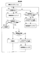
図4は、本実施の形態における印刷動作とキャリブレーション動作が競合するときの制御フローチャート図である。この制御は、エンジンコントローラ102により行われることを想定しているが、メインコントローラ101とエンジンコントローラ102とにより行われても良い。また、この制御は、4個または複数のブラックの現像ユニットが現像装置に装着されている状態、例えばモノクロ印刷モードを前提にしている。その場合、エンジンコントローラ102は、現在どの現像ユニットが使用中であるかの情報を不揮発性メモリ116aなどに格納しており、現像ロータリーを回転してその使用中の現像ユニットを現像位置まで回転移動させる。
FIG. 4 is a control flowchart when the printing operation and the calibration operation in the present embodiment compete. This control is assumed to be performed by the
まず、印刷ジョブが発生すると、メインコントローラ101により所定の画像処理が行われ、エンジンコントローラ102に印刷要求が出される(S10)。印刷要求がある(S10のYES)と、現在使用中の現像ユニットにおける過去の印刷枚数がカウントアップされる(S12)。このカウントアップ数は、プリンタが受け付けた印刷ジョブの枚数であっても良いし、単にエンジンコントローラに出される印刷単位の枚数であっても良い。また、この過去の印刷枚数は、現像ユニットの不揮発性メモリ51a〜54aまたは不揮発性メモリ116aに格納されている。そして、カウントアップされた印刷枚数が、キャリブレーションを実行すべき枚数(以下キャリブレーション枚数)以上になるか否かがチェックされ(S14)、キャリブレーション枚数に達していなければ(S14のNO)、現在使用対象の現像ユニットを使用して印刷が実行される(S16)。そして、印刷要求がある限り、現在使用対象の現像ユニットによる印刷が繰り返される。
First, when a print job is generated, predetermined image processing is performed by the
印刷要求があった時に、現在使用中の現像ユニットについてカウントアップされた印刷要求枚数がキャリブレーション枚数以上になる場合は(S14のYES)、その印刷要求を実行すると現像ユニットがキャリブレーション枚数に達してしまうことになり、印刷動作とキャリブレーション動作とが競合する。つまり、印刷動作を継続すれば最適ではない制御パラメータにより印刷動作が行われ、印刷画像の画質低下を招くおそれがあり、一方、キャリブレーション動作を優先すると、印刷動作が中断または待機され、印刷動作のスループットが低下する。 When there is a print request, if the number of print requests counted up for the development unit currently in use is equal to or greater than the number of calibrations (YES in S14), when the print request is executed, the development unit reaches the number of calibrations. As a result, the printing operation and the calibration operation compete. In other words, if the printing operation is continued, the printing operation is performed with a non-optimal control parameter, which may cause a reduction in image quality of the printed image. On the other hand, if the calibration operation is given priority, the printing operation is interrupted or waited, and the printing operation is performed. Throughput decreases.
そこで、本実施の形態では、現在使用中の現像ユニットについてカウントアップされた印刷枚数がキャリブレーション枚数以上になる場合は(S14のYES)、別の現像ユニットで未だキャリブレーション枚数に達していない現像ユニットがあるか否かがチェックされる(S18)。つまり、現在使用中の現像ユニットに変えて交換して使用可能な別の現像ユニット(トナーカートリッジ)が存在するが存在するか否かがチェックされ、存在する場合は(S18のYES)、現在受付済みの印刷要求枚数が所定の閾値枚数Vth未満か否かがチェックされる(S20)。もし、現在実行すべき印刷要求枚数が所定の閾値枚数Vth以上であれば(S20のYES)、使用可能な別の現像ユニットに交換して印刷を実行する。これにより、受け付けた印刷要求を優先的に処理することができ、且つ、キャリブレーション不要の現像ユニットを使用して印刷を実行するので、印刷画像の品質の低下を避けることができる。また、現在実行すべき印刷要求枚数が所定の閾値枚数Vth未満であれば(S20のNO)、現在使用中の現像ユニットを使用して印刷を実行する。印刷要求枚数が少なければ、キャリブレーションが必要になっている現像ユニットを使用しても、それほど印刷画像の品質低下にはならないし、現像ユニットを交換するために現像ロータリーを回転制御する必要もないので、印刷のスループットの低下を避けることができるからである。なお、エンジンコントローラ102は、工程S20の判断を行うために、メインコントローラ101から現在受付済みの印刷要求枚数の情報を受信する。
Therefore, in this embodiment, when the number of printed sheets counted up for the developing unit currently in use is equal to or greater than the number of calibrations (YES in S14), the development that has not yet reached the number of calibrations in another developing unit. It is checked whether there is a unit (S18). That is, it is checked whether there is another developing unit (toner cartridge) that can be used by replacing the developing unit currently in use, and if it exists (YES in S18), the current acceptance is made. It is checked whether the requested number of prints is less than a predetermined threshold number Vth (S20). If the requested number of prints to be currently executed is equal to or greater than the predetermined threshold number Vth (YES in S20), printing is performed after replacing with another usable development unit. As a result, the received print request can be preferentially processed, and printing is performed using a development unit that does not require calibration, so that it is possible to avoid deterioration in the quality of the printed image. If the requested number of prints to be executed is less than the predetermined threshold number Vth (NO in S20), printing is executed using the developing unit currently in use. If the required number of prints is small, even if a development unit that requires calibration is used, the quality of the printed image will not be reduced so much, and it is not necessary to control the rotation of the development rotary to replace the development unit. This is because a decrease in printing throughput can be avoided. Note that the
更に、別の現像ユニットで未だキャリブレーション枚数に達していない現像ユニットが存在しない場合は(S18のNO)、現在受付済みの印刷要求枚数が所定の閾値枚数Vth未満か否かがチェックされる(S26)。そして、現在実行すべき印刷要求枚数が所定の閾値枚数Vth未満であれば(S20のNO)、現在使用中の現像ユニットを使用して印刷を実行する。印刷要求枚数が少なければ、キャリブレーションが必要になっている現像ユニットを使用しても、それほど印刷画像の品質低下にはならないからである。一方、印刷要求枚数が所定の閾値枚数Vthを超えている場合は、印刷動作を待機させ、パッチパターンによるキャリブレーション動作を実行する(S28)。印刷要求枚数が多い場合は、印刷画質の低下を避けるために、キャリブレーション動作を優先させる必要があるからである。そして、キャリブレーション動作により、現在使用中の現像ユニットの制御パラメータが最適値に更新される。キャリブレーションが終了すると、その現像ユニットの印刷枚数情報がクリアされる(S30)。 Further, when there is no developing unit that has not yet reached the calibration number in another developing unit (NO in S18), it is checked whether or not the currently requested printing number is less than a predetermined threshold number Vth ( S26). If the requested number of prints to be executed is less than the predetermined threshold number Vth (NO in S20), printing is executed using the developing unit currently in use. This is because if the number of print requests is small, the quality of the printed image will not be reduced so much even if a developing unit that requires calibration is used. On the other hand, if the requested number of prints exceeds the predetermined threshold number Vth, the printing operation is waited and a calibration operation using a patch pattern is executed (S28). This is because when the number of print requests is large, it is necessary to prioritize the calibration operation in order to avoid deterioration in print image quality. The control parameter of the developing unit currently in use is updated to the optimum value by the calibration operation. When the calibration is completed, the print number information of the developing unit is cleared (S30).
上記のように、複数の同色の現像ユニットが装着されているので、現在使用中の現像ユニットについてキャリブレーションを実行すべきタイミングが来ても、他の現像ユニットで使用可能なものがある限りは、他の現像ユニットを使用して受付済みの印刷を実行することができる。そして、他に使用可能な現像ユニットがなくなった時点(S18のNO)で、印刷要求枚数が多い場合に初めて、現像ユニットに対するキャリブレーションが実行される。但し、他に使用可能な現像ユニットがなくたった時点でも、印刷要求枚数が少なければ(S26のYES)、キャリブレーションを後回しにして印刷が実行される。これにより、印刷のスループットの低下をできるだけ避けることができる。また、他に使用可能な現像ユニットが存在する場合でも、印刷要求枚数が少なければ(S20のNO)、キャリブレーションを後回しにして印刷が実行される。 As described above, since multiple development units of the same color are installed, even if it is time to execute calibration for the development unit currently in use, as long as there is something that can be used by other development units The received printing can be executed using another developing unit. Then, when there is no other usable development unit (NO in S18), calibration for the development unit is executed only when the number of requested prints is large. However, even when there is no other development unit that can be used, if the requested number of prints is small (YES in S26), the printing is executed after the calibration. Thereby, it is possible to avoid a decrease in printing throughput as much as possible. Even when there are other development units that can be used, if the requested number of prints is small (NO in S20), the printing is executed after the calibration.
やがて印刷が終了して印刷要求がなくなると(S10のNO)、後回しにしたキャリブレーション動作が実行される(S32,S34,S36)。つまり、印刷要求がない時に、印刷を優先した結果後回しにされていた現像ユニットのキャリブレーションを実行することで、印刷スループットの低下を回避してキャリブレーションを実行することができる。この後回しにしたキャリブレーション動作の実行(S32,S34,S36)は、例えば、メインコントローラ101からキャリブレーション実行許可を与えられたことに応答して行うようにしても良い。
When printing is finished and there is no print request (NO in S10), the post-calibration operation is executed (S32, S34, S36). That is, when there is no print request, calibration of the development unit that has been postponed as a result of giving priority to printing can be performed by avoiding a decrease in print throughput. The subsequent execution of the calibration operation (S32, S34, S36) may be performed in response to the calibration execution permission given from the
上記図4において、工程S14にて使用中の現像ユニットがキャリブレーション枚数に達することが判明した場合(S14のYES)、エンジンコントローラは、印刷要求枚数が閾値Vthを超えるか否かを先に判定してもよい。つまり、工程S20、S26を先に判定する。そして、印刷要求枚数が閾値Vthを超えていなければ、工程S24のように現在使用中の現像ユニットを使用して印刷を実行する。一方、印刷要求枚数が閾値Vthを超えていれば、他の現像ユニットが交換して使用可能か否かを判定し(工程S18)、可能なら、他の現像ユニットに交換して印刷を実行し、不可能なら印刷を待機させてキャリブレーションを実行する。 In FIG. 4, when it is found that the developing unit in use reaches the calibration number in step S14 (YES in S14), the engine controller first determines whether or not the requested number of prints exceeds the threshold value Vth. May be. That is, the processes S20 and S26 are determined first. If the requested number of prints does not exceed the threshold value Vth, printing is executed using the developing unit currently in use as in step S24. On the other hand, if the requested number of prints exceeds the threshold value Vth, it is determined whether another developing unit can be replaced and used (step S18). If possible, the printing is performed after replacing the developing unit with another developing unit. If not possible, wait for printing and execute calibration.
また、上記の場合に、印刷要求枚数が閾値Vthを超えていなくても、他の現像ユニットが交換して使用可能なら当該他の現像ユニットに交換して印刷を実行してもよい。 In the above case, even if the requested number of prints does not exceed the threshold value Vth, if another developing unit can be replaced and used, printing may be performed after replacing the other developing unit.
[変形例1]
図5は、本実施の形態における印刷動作とキャリブレーション動作が競合するときの制御フローチャート図の変形例である。この制御フローチャートも、複数の同色のトナーカートリッジが装着されたモノクロ印刷モードを前提としている。また、エンジンコントローラ102による制御を前提にしているが、メインコントローラ101とエンジンコントローラ102とにより行われてもよい。
[Modification 1]
FIG. 5 is a modified example of a control flowchart when the printing operation and the calibration operation in the present embodiment compete. This control flowchart also assumes a monochrome printing mode in which a plurality of toner cartridges of the same color are mounted. In addition, although control by the
この変形例では、カウントアップされた印刷枚数がキャリブレーション枚数以上になる場合(S14のYES)、交換可能な別のトナーカートリッジが存在する場合に(S18のYES)、印刷要求枚数の大小にかかわらず、別の使用可能なトナーカートリッジに交換して印刷を実行する(S40)。それ以外の動作は、図4と同じであり、各工程には同じ引用番号を与えている。つまり、この変形例では、複数のブラックの現像ユニットが同時に装着されていることを利用して、一つの現像ユニットがキャリブレーションを必要とするタイミングになると、他のキャリブレーションを必要としない現像ユニットに交換して、印刷を実行することを基本的制御とする。また、他の交換使用可能な現像ユニットが存在しない場合でも、印刷要求枚数が所定の閾値枚数より少ない場合には、キャリブレーションが必要になった現在の現像ユニットをそのまま使用して、印刷を実行し、印刷のスループットの低下をできるだけ抑えている。 In this modified example, when the counted number of printed sheets is equal to or greater than the number of calibration sheets (YES in S14), or when another toner cartridge that can be replaced exists (YES in S18), the number of print requests is large or small. First, the toner cartridge is replaced with another usable toner cartridge and printing is executed (S40). The other operations are the same as those in FIG. 4, and the same reference numbers are given to the respective steps. In other words, in this modification, by utilizing the fact that a plurality of black development units are mounted at the same time, when it is time for one development unit to require calibration, another development unit that does not require calibration. The basic control is to execute printing. Even if there is no other replaceable development unit, if the requested number of prints is less than the predetermined threshold number, printing is performed using the current development unit that requires calibration as it is. In addition, a decrease in printing throughput is suppressed as much as possible.
[変形例2]
図6は、本実施の形態における印刷動作とキャリブレーション動作が競合するときの制御フローチャート図の変形例である。この制御フローチャートは、CMYKの現像ユニットが装着されたカラー印刷モードにおけるモノクロ印刷を前提にしている。また、前述と同様に、エンジンコントローラ102による制御を前提にしているが、メインコントローラ101とエンジンコントローラ102とにより行われてもよい。
[Modification 2]
FIG. 6 is a modified example of a control flowchart when the printing operation and the calibration operation in the present embodiment compete. This control flowchart is premised on monochrome printing in a color printing mode in which a CMYK developing unit is mounted. Further, as described above, control by the
カラー印刷モードでは、CMYKのいずれかの現像ユニットがキャリブレーションタイミングに達すると、混合色の劣化を防止するために、カラー印刷の実行よりもキャリブレーションを優先することが望まれる。一方、カラー印刷モードにおけるモノクロ印刷では、一つのブラック現像ユニットを利用して印刷動作が実行される。その場合、そのブラック現像ユニットのキャリブレーション動作と印刷動作とが競合することが問題となる。 In the color printing mode, when any of the CMYK development units reaches the calibration timing, it is desirable to prioritize the calibration over the execution of the color printing in order to prevent the deterioration of the mixed color. On the other hand, in monochrome printing in the color printing mode, a printing operation is executed using one black developing unit. In that case, there is a problem that the calibration operation and the printing operation of the black developing unit compete.
そこで、この変形例では、ブラック現像ユニットの印刷枚数がキャリブレーション枚数以上になる場合は(S14)、印刷要求枚数が所定の閾値枚数Vth未満か否かがチェックされ(S50)、印刷要求枚数が所定の閾値枚数Vth未満の場合は(S50のYES)、キャリブレーション動作を待機させて、そのブラック現像ユニットを使用して印刷動作を行う(S52)。印刷要求枚数が少ないので、そのブラック現像ユニットで印刷してもそれほどの画質の低下にはならないからである。特に、モノクロ印刷では複数のトナー像を重ねる必要がないので、このような印刷が許されるのである。一方、印刷要求枚数が所定の閾値枚数Vth以上の場合は(S50のNO)、印刷を待機させて、キャリブレーションを実行する(S54)。キャリブレーションが実行されると、ブラック現像ユニットの過去の印刷枚数のカウント値がクリアされる(S56)。そして、ブラック現像ユニットの制御パラメータを最適値に更新した後に、印刷が実行される(S16)。 Therefore, in this modification, when the number of prints of the black developing unit is equal to or greater than the number of calibrations (S14), it is checked whether or not the print request number is less than a predetermined threshold number Vth (S50). If it is less than the predetermined threshold number Vth (YES in S50), the calibration operation is waited for and the printing operation is performed using the black developing unit (S52). This is because the requested number of prints is small, and even if printing is performed with the black developing unit, the image quality does not deteriorate so much. In particular, in monochrome printing, it is not necessary to superimpose a plurality of toner images, and such printing is allowed. On the other hand, if the print request number is equal to or greater than the predetermined threshold number Vth (NO in S50), the printer waits for printing and executes calibration (S54). When calibration is executed, the count value of the past number of printed sheets of the black developing unit is cleared (S56). Then, after updating the control parameter of the black developing unit to the optimum value, printing is executed (S16).
また、この変形例でも、キャリブレーションを待機させて印刷動作を優先した場合は、印刷要求がなくなった時点で(S10のNO)、または、メインコントローラ101からのキャリブレーション許可通知を受信した時点で(図示せず)、キャリブレーション動作(S32,S34,S36)を実行する。
Also in this modified example, when the print operation is prioritized by waiting for calibration, when the print request is lost (NO in S10) or when the calibration permission notification from the
図3,4,5の制御フローチャートでは、印刷を優先するかキャリブレーションを優先するかの判断を、エンジンコントローラ102が、メインコントローラ101から受信した受付済み印刷要求の印刷枚数の情報に基づいて行っているが、この判断を、メインコントローラ101側で行い、いずれを優先すべきかの命令をメインコントローラ101がエンジンコントローラ102に通知するようにしてもよい。
In the control flowcharts of FIGS. 3, 4, and 5, the
以上、実施の形態によれば、複数の同色現像ユニットが装着されていることを利用して、印刷動作のスループットの低下を回避してキャリブレーション動作を実行することができる。また、カラー印刷モードでも、モノクロ印刷であれば、同様に印刷動作のスループットの低下を回避してキャリブレーション動作を実行することができる。 As described above, according to the embodiment, it is possible to execute the calibration operation while avoiding a decrease in the throughput of the printing operation by utilizing the fact that a plurality of the same color developing units are mounted. Even in the color printing mode, if the printing is monochrome, the calibration operation can be executed while avoiding a decrease in the throughput of the printing operation.
10:画像形成装置(プリンタ)、20:像担持体(感光体ドラム)、40:露光ユニット
50:現像装置、51〜54:現像ユニット、100:制御ユニット、
101:メインコントローラ、102:エンジンコントローラ
10: image forming apparatus (printer), 20: image carrier (photosensitive drum), 40: exposure unit 50: developing device, 51-54: developing unit, 100: control unit,
101: Main controller, 102: Engine controller
Claims (4)
同色の現像剤を収納する複数の現像ユニットが着脱自在に装着される現像装置と、
印刷要求に応答して前記像担持体の潜像に前記現像ユニットの現像剤を付着させて現像を行う印刷動作と、前記像担持体にパッチパターンを現像してキャリブレーションを行うキャリブレーション動作とを制御する制御手段とを有し、
前記制御手段は、前記印刷要求の印刷動作を実行すると使用中の第1の現像ユニットのキャリブレーションタイミングに達する場合に、
キャリブレーションタイミングに達しない第2の現像ユニットが存在する場合は、当該第2の現像ユニットを使用して印刷動作を実行し、
前記キャリブレーションタイミングに達しない第2の現像ユニットが存在しない場合は、前記印刷要求の印刷要求枚数が所定閾値を超えない場合に前記第1の現像ユニットを使用して印刷動作を実行し、前記所定閾値を超える場合に前記キャリブレーション動作を実行しその後印刷動作を実行することを特徴とする画像形成装置。 An image carrier on which a latent image is formed;
A developing device in which a plurality of developing units containing the same color developer are detachably mounted; and
A printing operation in which a developer of the developing unit is attached to a latent image on the image carrier in response to a print request and development is performed; and a calibration operation in which a patch pattern is developed on the image carrier to perform calibration. Control means for controlling
When the control means reaches the calibration timing of the first developing unit in use when the printing operation of the print request is executed,
If there is a second developing unit that does not reach the calibration timing, a printing operation is executed using the second developing unit,
When there is no second developing unit that does not reach the calibration timing, a printing operation is performed using the first developing unit when the number of print requests for the print request does not exceed a predetermined threshold, An image forming apparatus, wherein when the predetermined threshold value is exceeded, the calibration operation is executed and then the printing operation is executed.
前記制御手段は、前記キャリブレーションタイミングに達しない第2の現像ユニットが存在する場合でも、前記印刷要求の印刷要求枚数が所定閾値を超えない場合は前記第1の現像ユニットを使用して印刷動作を実行し、前記所定閾値を超える場合は当該第2の現像ユニットを使用して印刷動作を実行することを特徴とする画像形成装置。 In claim 1,
Even when there is a second developing unit that does not reach the calibration timing, the control means performs a printing operation using the first developing unit when the number of print requests for the print request does not exceed a predetermined threshold. The image forming apparatus is configured to execute a printing operation using the second developing unit when the predetermined threshold value is exceeded.
同色の現像剤を収納する複数の現像ユニットが着脱自在に装着される現像装置と、
印刷要求に応答して前記像担持体の潜像に前記現像ユニットの現像剤を付着させて現像を行う印刷動作と、前記像担持体にパッチパターンを現像してキャリブレーションを行うキャリブレーション動作とを制御する制御手段とを有し、
前記制御手段は、前記印刷要求の印刷動作を実行すると使用中の第1の現像ユニットのキャリブレーションタイミングに達する場合に、
前記印刷要求の印刷要求枚数が所定閾値を超えない場合は、当該使用中の第1の現像ユニットを使用して印刷動作を実行し、
前記印刷要求の印刷要求枚数が所定閾値を超える場合は、キャリブレーションタイミングに達しない第2の現像ユニットが存在する場合には、当該第2の現像ユニットを使用して印刷動作を実行し、前記キャリブレーションタイミングに達しない第2の現像ユニットが存在しない場合には、前記キャリブレーション動作を実行しその後印刷動作を実行することを特徴とする画像形成装置。 An image carrier on which a latent image is formed;
A developing device in which a plurality of developing units containing the same color developer are detachably mounted; and
A printing operation in which a developer of the developing unit is attached to a latent image on the image carrier in response to a print request and development is performed; and a calibration operation in which a patch pattern is developed on the image carrier to perform calibration. Control means for controlling
When the control means reaches the calibration timing of the first developing unit in use when the printing operation of the print request is executed,
If the print request number of the print request does not exceed a predetermined threshold, a printing operation is executed using the first developing unit in use,
When the print request number of print requests exceeds a predetermined threshold, if there is a second development unit that does not reach the calibration timing, a printing operation is performed using the second development unit, An image forming apparatus, wherein when there is no second developing unit that does not reach the calibration timing, the calibration operation is executed, and then the printing operation is executed.
前記制御手段は、前記印刷要求の印刷要求枚数が所定閾値を超えない場合でも、キャリブレーションタイミングに達しない第2の現像ユニットが存在しない場合に前記第1の現像ユニットを使用して印刷動作を実行し、前記キャリブレーションタイミングに達しない第2の現像ユニットが存在する場合は当該第2の現像ユニットを使用して印刷動作を実行することを特徴とする画像形成装置。 In claim 3,
The control means performs a printing operation using the first development unit when there is no second development unit that does not reach the calibration timing even when the print request number of print requests does not exceed a predetermined threshold. An image forming apparatus that executes and performs a printing operation using the second developing unit when there is a second developing unit that does not reach the calibration timing.
Priority Applications (2)
| Application Number | Priority Date | Filing Date | Title |
|---|---|---|---|
| JP2004150451A JP4461906B2 (en) | 2004-05-20 | 2004-05-20 | Image forming apparatus that performs calibration without reducing printing throughput |
| US11/133,467 US7251421B2 (en) | 2004-05-20 | 2005-05-20 | Image forming apparatus for performing calibration without reducing throughput in printing |
Applications Claiming Priority (1)
| Application Number | Priority Date | Filing Date | Title |
|---|---|---|---|
| JP2004150451A JP4461906B2 (en) | 2004-05-20 | 2004-05-20 | Image forming apparatus that performs calibration without reducing printing throughput |
Publications (3)
| Publication Number | Publication Date |
|---|---|
| JP2005331740A JP2005331740A (en) | 2005-12-02 |
| JP2005331740A5 JP2005331740A5 (en) | 2006-06-15 |
| JP4461906B2 true JP4461906B2 (en) | 2010-05-12 |
Family
ID=35486444
Family Applications (1)
| Application Number | Title | Priority Date | Filing Date |
|---|---|---|---|
| JP2004150451A Expired - Fee Related JP4461906B2 (en) | 2004-05-20 | 2004-05-20 | Image forming apparatus that performs calibration without reducing printing throughput |
Country Status (2)
| Country | Link |
|---|---|
| US (1) | US7251421B2 (en) |
| JP (1) | JP4461906B2 (en) |
Families Citing this family (10)
| Publication number | Priority date | Publication date | Assignee | Title |
|---|---|---|---|---|
| JP2006305827A (en) * | 2005-04-27 | 2006-11-09 | Brother Ind Ltd | Image forming system and image forming apparatus |
| JP2007193056A (en) * | 2006-01-18 | 2007-08-02 | Kyocera Mita Corp | Image forming apparatus |
| JP4333732B2 (en) * | 2006-11-30 | 2009-09-16 | コニカミノルタビジネステクノロジーズ株式会社 | Color image forming apparatus |
| KR101231643B1 (en) * | 2006-12-11 | 2013-02-08 | 삼성전자주식회사 | Image forming apparatus and control method thereof |
| KR20080073599A (en) * | 2007-02-06 | 2008-08-11 | 삼성전자주식회사 | Image forming apparatus and toner sensor status sensing method thereof |
| JP5156484B2 (en) * | 2008-05-28 | 2013-03-06 | 京セラドキュメントソリューションズ株式会社 | Image forming apparatus |
| JP5961988B2 (en) * | 2010-12-16 | 2016-08-03 | 株式会社リコー | Image forming apparatus, control method thereof, program, and computer-readable recording medium |
| JP6057729B2 (en) * | 2013-01-16 | 2017-01-11 | キヤノン株式会社 | Image forming apparatus |
| JP6418875B2 (en) * | 2014-10-01 | 2018-11-07 | キヤノン株式会社 | Image forming apparatus |
| JP6468829B2 (en) * | 2014-12-12 | 2019-02-13 | キヤノン株式会社 | Image forming apparatus |
Family Cites Families (12)
| Publication number | Priority date | Publication date | Assignee | Title |
|---|---|---|---|---|
| JPH0740152B2 (en) * | 1984-12-15 | 1995-05-01 | ミノルタ株式会社 | Image forming device |
| JPS63306477A (en) * | 1987-06-08 | 1988-12-14 | Minolta Camera Co Ltd | Developing unit control method for image forming device |
| JP3408119B2 (en) * | 1996-08-23 | 2003-05-19 | キヤノン株式会社 | Image processing apparatus and method, and recording medium |
| JP2000015896A (en) | 1998-06-30 | 2000-01-18 | Canon Inc | Image processing apparatus and image processing method |
| JP2001109219A (en) * | 1999-10-07 | 2001-04-20 | Canon Inc | Color image forming device |
| JP2002229278A (en) | 2001-01-30 | 2002-08-14 | Canon Inc | Calibration method, printer and image processor |
| JP3945188B2 (en) * | 2001-05-25 | 2007-07-18 | セイコーエプソン株式会社 | Image forming apparatus |
| JP2003035978A (en) * | 2001-07-23 | 2003-02-07 | Canon Inc | Image forming apparatus |
| JP2003035977A (en) * | 2001-07-23 | 2003-02-07 | Canon Inc | Image forming apparatus |
| JP2003316106A (en) | 2002-04-23 | 2003-11-06 | Canon Inc | Image recorder, control method therefor, and developing unit |
| US7426352B2 (en) * | 2002-10-24 | 2008-09-16 | Canon Kabushiki Kaisha | Image formation apparatus |
| US7437102B2 (en) * | 2004-03-18 | 2008-10-14 | Seiko Epson Corporation | Image forming apparatus with controlled adjustment of toner stored in developing cartridge |
-
2004
- 2004-05-20 JP JP2004150451A patent/JP4461906B2/en not_active Expired - Fee Related
-
2005
- 2005-05-20 US US11/133,467 patent/US7251421B2/en not_active Expired - Fee Related
Also Published As
| Publication number | Publication date |
|---|---|
| US20060008285A1 (en) | 2006-01-12 |
| US7251421B2 (en) | 2007-07-31 |
| JP2005331740A (en) | 2005-12-02 |
Similar Documents
| Publication | Publication Date | Title |
|---|---|---|
| US7251421B2 (en) | Image forming apparatus for performing calibration without reducing throughput in printing | |
| US7286775B2 (en) | Image formation device enabling switching display of remaining developing agent in monochrome printing mode | |
| JP2008238459A (en) | Printer | |
| US20060002729A1 (en) | Image forming apparatus with reduced printing time | |
| JP2005195843A (en) | Image forming apparatus capable of changing over color printing mode and monochrome printing mode | |
| US8995004B2 (en) | Control apparatus of non-volatile memory and image forming apparatus | |
| JP2007010745A (en) | Image forming apparatus and resist adjustment method for the device | |
| US7233749B2 (en) | Image forming device for performing calibration by patch pattern | |
| JP4363402B2 (en) | Image forming apparatus capable of displaying total amount of remaining developer in monochrome printing mode | |
| US7317880B2 (en) | Image forming device for controlling density adjustment based on a type of development unit | |
| JP3969392B2 (en) | Image forming apparatus capable of switching between color printing mode and monochrome printing mode | |
| US7460817B2 (en) | Image forming apparatus | |
| JPH1115216A (en) | Image processor, control method therefor and record medium | |
| US20080292357A1 (en) | Image Forming Apparatus, Computer-Readable Medium, Image Forming System, and Image Forming Method | |
| JP2005246723A (en) | Image forming apparatus and driver program | |
| JP2007240916A (en) | Image forming apparatus, and control method and program for same | |
| JP2005352409A (en) | Image forming apparatus | |
| JP2005321709A (en) | Image forming apparatus using specified developing unit for management operation | |
| JP4600101B2 (en) | Image forming apparatus and adjustment method thereof | |
| JP2006231697A (en) | Image forming device and firmware overwriting method | |
| JP2006003498A (en) | Image forming apparatus and driver program | |
| JP2022076201A (en) | Image forming apparatus | |
| JPH11338217A (en) | Image forming device | |
| JP2005292771A (en) | Image forming apparatus | |
| JP2007114535A (en) | Image forming apparatus, control method and control program for the apparatus |
Legal Events
| Date | Code | Title | Description |
|---|---|---|---|
| A521 | Written amendment |
Free format text: JAPANESE INTERMEDIATE CODE: A523 Effective date: 20060427 |
|
| A621 | Written request for application examination |
Free format text: JAPANESE INTERMEDIATE CODE: A621 Effective date: 20060427 |
|
| A977 | Report on retrieval |
Free format text: JAPANESE INTERMEDIATE CODE: A971007 Effective date: 20090520 |
|
| A131 | Notification of reasons for refusal |
Free format text: JAPANESE INTERMEDIATE CODE: A131 Effective date: 20090602 |
|
| A131 | Notification of reasons for refusal |
Free format text: JAPANESE INTERMEDIATE CODE: A131 Effective date: 20091006 |
|
| A521 | Written amendment |
Free format text: JAPANESE INTERMEDIATE CODE: A523 Effective date: 20091119 |
|
| TRDD | Decision of grant or rejection written | ||
| A01 | Written decision to grant a patent or to grant a registration (utility model) |
Free format text: JAPANESE INTERMEDIATE CODE: A01 Effective date: 20100126 |
|
| A01 | Written decision to grant a patent or to grant a registration (utility model) |
Free format text: JAPANESE INTERMEDIATE CODE: A01 |
|
| A61 | First payment of annual fees (during grant procedure) |
Free format text: JAPANESE INTERMEDIATE CODE: A61 Effective date: 20100208 |
|
| FPAY | Renewal fee payment (event date is renewal date of database) |
Free format text: PAYMENT UNTIL: 20130226 Year of fee payment: 3 |
|
| R150 | Certificate of patent or registration of utility model |
Free format text: JAPANESE INTERMEDIATE CODE: R150 |
|
| LAPS | Cancellation because of no payment of annual fees |