JP4635462B2 - Fuel cell with porous separator - Google Patents
Fuel cell with porous separator Download PDFInfo
- Publication number
- JP4635462B2 JP4635462B2 JP2004091168A JP2004091168A JP4635462B2 JP 4635462 B2 JP4635462 B2 JP 4635462B2 JP 2004091168 A JP2004091168 A JP 2004091168A JP 2004091168 A JP2004091168 A JP 2004091168A JP 4635462 B2 JP4635462 B2 JP 4635462B2
- Authority
- JP
- Japan
- Prior art keywords
- layer
- fuel cell
- passage
- diffusion layer
- separator
- Prior art date
- Legal status (The legal status is an assumption and is not a legal conclusion. Google has not performed a legal analysis and makes no representation as to the accuracy of the status listed.)
- Expired - Fee Related
Links
Images


Classifications
-
- Y—GENERAL TAGGING OF NEW TECHNOLOGICAL DEVELOPMENTS; GENERAL TAGGING OF CROSS-SECTIONAL TECHNOLOGIES SPANNING OVER SEVERAL SECTIONS OF THE IPC; TECHNICAL SUBJECTS COVERED BY FORMER USPC CROSS-REFERENCE ART COLLECTIONS [XRACs] AND DIGESTS
- Y02—TECHNOLOGIES OR APPLICATIONS FOR MITIGATION OR ADAPTATION AGAINST CLIMATE CHANGE
- Y02E—REDUCTION OF GREENHOUSE GAS [GHG] EMISSIONS, RELATED TO ENERGY GENERATION, TRANSMISSION OR DISTRIBUTION
- Y02E60/00—Enabling technologies; Technologies with a potential or indirect contribution to GHG emissions mitigation
- Y02E60/30—Hydrogen technology
- Y02E60/50—Fuel cells
Landscapes
- Fuel Cell (AREA)
- Inert Electrodes (AREA)
Description
本発明は、燃料電池に関し、特に、隣接する2つのセルの間に設けられるセパレータの技術に関する。 The present invention relates to a fuel cell, and more particularly to a separator technology provided between two adjacent cells.
燃料電池は、複数のセルを含んでおり、隣接する2つのセルの間には、セパレータが設けられている。 The fuel cell includes a plurality of cells, and a separator is provided between two adjacent cells.
特許文献1では、隣接する2つのセルの間には、2つのセパレータが設けられている。各セパレータは、双方の面に複数の凸部を有しており、凹部によって流路が形成されている。第1のセパレータは、第1の面側に形成された複数の凸部において第1のMEA(イオン交換膜電解質/電極組立体)と接触しており、第1のセパレータと第1のMEAとの間には、凹部によって水素ガスが通る水素ガス流路が形成されている。同様に、第2のセパレータは、第1の面側に形成された複数の凸部において第2のMEAと接触しており、第2のセパレータと第2のMEAとの間には、凹部によって空気(酸素ガス)が通る酸素ガス流路が形成されている。また、第1のセパレータの第2の面側に形成された複数の凸部は、第2のセパレータの第2の面側に形成された複数の凸部と接触しており、2つのセパレータの間には、対向する凹部によって冷却水が通る冷却水流路が形成される。 In Patent Document 1, two separators are provided between two adjacent cells. Each separator has a plurality of convex portions on both surfaces, and a flow path is formed by the concave portions. The first separator is in contact with the first MEA (ion exchange membrane electrolyte / electrode assembly) at the plurality of convex portions formed on the first surface side, and the first separator, the first MEA, A hydrogen gas flow path through which hydrogen gas passes is formed between the recesses. Similarly, the second separator is in contact with the second MEA at the plurality of convex portions formed on the first surface side, and a concave portion is provided between the second separator and the second MEA. An oxygen gas flow path through which air (oxygen gas) passes is formed. In addition, the plurality of convex portions formed on the second surface side of the first separator are in contact with the plurality of convex portions formed on the second surface side of the second separator, and the two separators A cooling water flow path through which the cooling water passes is formed between the concave portions facing each other.
カソードで生成された水(生成水)は、多孔質の第2のセパレータを透過して、冷却水流路へ移動する。これにより、酸素ガス流路内におけるフラッディング状態の発生を抑制することができる。なお、生成水の移動は、酸素ガスの圧力と冷却水の圧力との間に、所定の圧力差を発生させることによって、実現されている。 The water (generated water) generated at the cathode permeates the porous second separator and moves to the cooling water flow path. Thereby, generation | occurrence | production of the flooding state in an oxygen gas flow path can be suppressed. The movement of the generated water is realized by generating a predetermined pressure difference between the pressure of the oxygen gas and the pressure of the cooling water.
しかしながら、従来の技術では、カソードで生成された水を多孔質のセパレータを介して効率よく除去することが困難であるという問題があった。これは、多孔質のセパレータの凸部の頂面から吸収された水分の一部が、該凸部の側面や該凸部の周囲の底面を介して、酸素ガス流路内へ流出してしまうためである。 However, the conventional technique has a problem that it is difficult to efficiently remove water generated at the cathode through the porous separator. This is because part of the water absorbed from the top surface of the convex portion of the porous separator flows out into the oxygen gas flow path through the side surface of the convex portion and the bottom surface around the convex portion. Because.
この発明は、従来技術における上述の課題を解決するためになされたものであり、電極で生成された水分をセパレータを介して効率よく除去することを目的とする。 The present invention has been made to solve the above-described problems in the prior art, and an object thereof is to efficiently remove moisture generated by an electrode through a separator.
上述の課題の少なくとも一部を解決するため、本発明の装置は、燃料電池であって、
電解質層と、
前記電解質層の一方の側に設けられた第1の電極層と、
前記電解質層の前記一方の側に設けられた第1のガス拡散層であって、前記第1のガス拡散層と前記電解質層との間には、前記第1の電極層が設けられている、前記第1のガス拡散層と、
前記電解質層の前記一方の側に設けられた第1のセパレータであって、前記第1のセパレータと前記第1の電極層との間には、前記第1のガス拡散層が設けられており、前記第1のセパレータの第1の側には、前記第1のガス拡散層を介して前記第1の電極層に反応ガスを供給するための反応ガス通路が形成されている、前記第1のセパレータと、
を備え、
前記第1のセパレータは、
前記第1の側に、前記第1のガス拡散層に接触する接触面と、前記第1のガス拡散層に接触せずに前記反応ガス通路を形成する通路形成面と、を有する多孔質部と、
前記通路形成面に形成され、前記多孔質部よりも小さな気孔率を有する表層と、
を備え、
前記燃料電池は、さらに、前記第1のガス拡散層上の前記通路形成面に対応する第1の部分領域であって、前記第1のガス拡散層と前記第1のセパレータとの間の前記第1の部分領域に設けられた第1の撥水層を備えることを特徴とする。
In order to solve at least a part of the problems described above, an apparatus of the present invention is a fuel cell,
An electrolyte layer;
A first electrode layer provided on one side of the electrolyte layer;
A first gas diffusion layer provided on the one side of the electrolyte layer, wherein the first electrode layer is provided between the first gas diffusion layer and the electrolyte layer. The first gas diffusion layer;
A first separator provided on the one side of the electrolyte layer, wherein the first gas diffusion layer is provided between the first separator and the first electrode layer. The first side of the first separator is formed with a reaction gas passage for supplying a reaction gas to the first electrode layer through the first gas diffusion layer. A separator of
With
The first separator is
A porous part having a contact surface in contact with the first gas diffusion layer on the first side and a passage forming surface that forms the reaction gas passage without contacting the first gas diffusion layer. When,
A surface layer formed on the passage forming surface and having a porosity smaller than that of the porous portion;
Equipped with a,
The fuel cell is further a first partial region corresponding to the passage forming surface on the first gas diffusion layer, and the fuel cell is located between the first gas diffusion layer and the first separator. comprising a first water-repellent layer provided on the first partial region, characterized in Rukoto.
この装置では、多孔質部の通路形成面には、多孔質部よりも小さな気孔率を有する表層が形成されている。このため、電極(第1の電極層または他の電極層)で生成されて第1のガス拡散層内に存在する水分が、多孔質部の接触面を介して多孔質部に吸収された後に、通路形成面を介して反応ガス通路内へ流出するのを抑制することができる。この結果、電極で生成された水分を第1のセパレータを介して効率よく除去することが可能となる。また、この装置では、水分が第1のガス拡散層を介して反応ガス通路内へ移動するのを抑制することができ、この結果、多孔質部は、接触面を介して水分を効率よく吸収することができる。
In this apparatus, a surface layer having a porosity smaller than that of the porous portion is formed on the passage forming surface of the porous portion. For this reason, after the water | moisture content produced | generated by the electrode (a 1st electrode layer or another electrode layer) and existing in a 1st gas diffusion layer is absorbed by the porous part via the contact surface of a porous part. , It is possible to suppress the flow out into the reaction gas passage through the passage formation surface. As a result, it is possible to efficiently remove the moisture generated by the electrode through the first separator. In addition, in this apparatus, it is possible to suppress the movement of moisture into the reaction gas passage through the first gas diffusion layer, and as a result, the porous portion efficiently absorbs moisture through the contact surface. can do.
上記の装置において、
前記表層は、緻密質層であることが好ましい。
In the above device,
The surface layer is preferably a dense layer.
こうすれば、多孔質部に吸収された水分が通路形成面から流出するのを確実に抑制することができる。 If it carries out like this, it can suppress reliably that the water | moisture content absorbed by the porous part flows out from a channel | path formation surface.
上記の装置において、
前記表層が形成される前記通路形成面上の領域は、前記第1のガス拡散層から離れた領域であることが好ましい。
In the above device,
Realm on the passage forming surface on which the surface layer is formed is preferably the remote from the first gas diffusion layer region.
この場合には、表層が接触面の近傍領域に形成されていないため、接触面の近傍領域を介して第1の電極層に反応ガスが与えられる。このため、表層が該近傍領域に形成される場合と比較して、前記第1の電極層により多くの反応ガスを供給することができ、この結果、燃料電池の出力電圧の低下を抑制することができる。 In this case, since the surface layer is not formed in the region near the contact surface, the reaction gas is given to the first electrode layer through the region near the contact surface. For this reason, compared with the case where the surface layer is formed in the vicinity region, more reactive gas can be supplied to the first electrode layer, and as a result, a decrease in the output voltage of the fuel cell can be suppressed. Can do.
また、上記の装置において、さらに、
前記第1の電極層と前記第1のガス拡散層との間の前記通路形成面に対応する第2の部分領域に設けられた第2の撥水層を備えるようにしてもよい。
Moreover, in the above apparatus,
You may make it provide the 2nd water repellent layer provided in the 2nd partial area | region corresponding to the said channel | path formation surface between the said 1st electrode layer and the said 1st gas diffusion layer.
上記の装置において、
前記接触面には、親水処理が施されていることが好ましい。
In the above device,
The contact surface is preferably subjected to a hydrophilic treatment.
こうすれば、多孔質部は、接触面を介して水分を効率よく吸収することができる。 If it carries out like this, a porous part can absorb a water | moisture content efficiently via a contact surface.
上記の装置において、
前記多孔質部の内部には、撥水処理が施されていることが好ましい。
In the above device,
It is preferable that a water repellent treatment is performed inside the porous portion.
こうすれば、多孔質部は、吸収した水分を速やかに移動させることができる。 If it carries out like this, the porous part can move the absorbed water | moisture content rapidly.
上記の装置において、
前記多孔質部の第2の側の表面には、親水処理が施されていることが好ましい。
In the above device,
The surface on the second side of the porous part is preferably subjected to a hydrophilic treatment.
こうすれば、多孔質部は、吸収した水分を第2の側から効率よく放出することができる。 By so doing, the porous portion can efficiently release the absorbed moisture from the second side.
上記の装置において、さらに、
前記電解質層の他方の側に設けられた第2の電極層と、
前記電解質層の前記他方の側に設けられた第2のガス拡散層であって、前記第2のガス拡散層と前記電解質層との間には、前記第2の電極層が設けられている、前記第2のガス拡散層と、
前記第2の電極層と前記第2のガス拡散層との間に設けられた第3の撥水層と、
を備えることが好ましい。
In the above apparatus,
A second electrode layer provided on the other side of the electrolyte layer;
A second gas diffusion layer provided on the other side of the electrolyte layer, wherein the second electrode layer is provided between the second gas diffusion layer and the electrolyte layer. The second gas diffusion layer;
A third water-repellent layer provided between the second electrode layer and the second gas diffusion layer;
It is preferable to provide.
こうすれば、電解質層の他方の側への水分の移動を抑制することができるため、多孔質部は、接触面を介して水分を効率よく吸収することができる。 By so doing, the movement of moisture to the other side of the electrolyte layer can be suppressed, so that the porous portion can efficiently absorb moisture via the contact surface.
あるいは、上記の装置において、さらに、
前記電解質層の他方の側に設けられた第2の電極層と、
前記電解質層の前記他方の側に設けられ第2のガス拡散層であって、前記第2のガス拡散層と前記電解質層との間には、前記第2の電極層が設けられている、前記第2のガス拡散層と、
前記電解質層の前記他方の側に設けられた第2のセパレータであって、前記第2のセパレータと前記第2の電極層との間には、前記第2のガス拡散層が設けられている、前記第2のセパレータと、
前記第2のガス拡散層と前記第2のセパレータとの間に設けられた第4の撥水層と、
を備えるようにしてもよい。
Alternatively, in the above apparatus,
A second electrode layer provided on the other side of the electrolyte layer;
A second gas diffusion layer provided on the other side of the electrolyte layer, wherein the second electrode layer is provided between the second gas diffusion layer and the electrolyte layer, The second gas diffusion layer;
A second separator provided on the other side of the electrolyte layer, wherein the second gas diffusion layer is provided between the second separator and the second electrode layer. The second separator;
A fourth water repellent layer provided between the second gas diffusion layer and the second separator;
You may make it provide.
上記の装置において、
前記多孔質部は、前記反応ガス通路の下流側の部位に配置されているようにしてもよい。
In the above device,
The porous portion may be disposed at a site downstream of the reaction gas passage.
こうすれば、第1のセパレータは、水分が比較的多い反応ガス通路の下流側の部位から水分を除去することができる。 In this way, the first separator can remove moisture from the downstream portion of the reaction gas passage with relatively much moisture.
上記の装置において、
前記反応ガスは、空気であることが好ましい。
In the above device,
The reaction gas is preferably air.
上記の装置において、
前記多孔質部の第2の側には、冷却ガスが通る冷却ガス通路が形成されており、
前記冷却ガス通路内には、空気が供給され、
前記燃料電池は、さらに、
前記冷却ガス通路を経由した空気を、前記反応ガス通路に供給するための供給通路を備えることが好ましい。
In the above device,
A cooling gas passage through which a cooling gas passes is formed on the second side of the porous portion,
Air is supplied into the cooling gas passage,
The fuel cell further includes:
It is preferable to provide a supply passage for supplying air that has passed through the cooling gas passage to the reaction gas passage.
こうすれば、冷却ガス通路内で加湿された空気を反応ガス通路に供給することができ、水分が比較的少ない反応ガス通路の上流側の乾燥を抑制することができる。 If it carries out like this, the air humidified in the cooling gas channel | path can be supplied to a reaction gas channel | path, and the drying of the upstream of the reaction gas channel | path with comparatively little water | moisture content can be suppressed.
なお、この発明は、種々の形態で実現することが可能であり、例えば、燃料電池、該燃料電池を備える燃料電池システム、該燃料電池システムを搭載した移動体などの装置等の形態で実現することができる。 Note that the present invention can be realized in various forms, for example, in the form of a fuel cell, a fuel cell system including the fuel cell, and a device such as a moving body equipped with the fuel cell system. be able to.
次に、本発明の実施の形態を実施例に基づき以下の順序で説明する。
A.第1参考例:
A−1.燃料電池システムの全体構成:
A−2.セルの概略構成:
A−3.セルの具体的な構成:
B.実施例:
C.第2参考例:
D.第3参考例:
E.第4参考例:
F.第5参考例:
Next, embodiments of the present invention will be described in the following order based on examples.
A. First reference example:
A-1. Overall configuration of the fuel cell system:
A-2. Cell schematic configuration:
A-3. Specific cell configuration:
B. Real施例:
C. Second reference example:
D. Third reference example:
E. Fourth reference example:
F. Fifth reference example:
A.第1参考例:
A−1.燃料電池システムの全体構成:
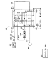
図1は、第1参考例における燃料電池システムの概略構成を示す説明図である。なお、この燃料電池システムは、車両に搭載されている。
A. First reference example:
A-1. Overall configuration of the fuel cell system:
FIG. 1 is an explanatory diagram showing a schematic configuration of a fuel cell system in a first reference example. The fuel cell system is mounted on a vehicle.
燃料電池システムは、燃料電池スタック100と、燃料電池スタックに燃料ガス(水素ガス)を供給するための燃料ガス供給系と、燃料電池スタックに空気を供給するための空気供給系と、燃料電池スタックに冷却液を供給するための冷却液供給系と、を備えている。また、燃料電池システムは、システム全体の動作を制御するためのコントローラ600を備えている。
The fuel cell system includes a
燃料電池スタック(以下、単に「スタック」とも呼ぶ)100は、比較的小型で発電効率に優れる固体高分子型燃料電池である。スタック100は、積層された複数のセルを含んでいる。また、スタック100内部には、複数の内部通路が設けられている。具体的には、スタック内部には、燃料ガスが通る内部燃料ガス通路210と、酸化ガス(空気)が通る内部酸化ガス通路220と、冷却液が通る内部冷却液通路230と、冷却ガス(空気)が通る内部冷却ガス通路240と、が設けられている。
A fuel cell stack (hereinafter also simply referred to as “stack”) 100 is a polymer electrolyte fuel cell that is relatively small and excellent in power generation efficiency. The
燃料ガス供給系は、水素タンク302と、減圧弁304と、流量制御弁306と、を備えている。水素タンク302は、水素ガス(燃料ガス)を比較的高い圧力で貯蔵している。減圧弁304は、水素タンク302から供給された燃料ガスを所定の圧力に減圧する。流量制御弁306は、燃料ガスの流量を調整する。燃料ガスは、燃料ガス通路310を介してスタック100に供給される。燃料ガスは、内部燃料ガス通路210を通る際に、スタック内部での電気化学反応に利用される。内部燃料ガス通路210を通過した使用済みの燃料オフガスは、燃料オフガス通路390を介して外部に排出される。燃料オフガス通路390には、遮断弁392が設けられている。遮断弁392は、間欠的に開状態に設定され、これにより、燃料オフガスがスタック100から排出される。
The fuel gas supply system includes a
空気供給系は、空気ブロワ402を備えている。空気は、空気通路を介してスタック100に供給される。ここで、空気通路は、スタック外部に設けられた第1および第2の外部空気通路410,420と、内部冷却ガス通路240と、を含んでいる。空気は、内部冷却ガス通路240を通る際には、冷却ガスとして機能し、スタック100を冷却する。また、空気は、内部酸化ガス通路220を通る際には、酸化ガスとして機能し、スタック内部での電気化学反応に利用される。内部酸化ガス通路220を通過した使用済みの空気(酸化オフガス)は、酸化オフガス通路490を介して外部に排出される。
The air supply system includes an
冷却液供給系は、循環ポンプ502と、熱交換器504と、を備えている。循環ポンプ502は、スタック外部に設けられた循環通路510と、内部冷却液通路230と、の間で冷却液(例えば水)を循環させる。冷却液は、内部冷却液通路230を通る際に、スタック100を冷却する。熱交換器504は、スタック100から排出された比較的温度の高い冷却液を冷却する。
The coolant supply system includes a
なお、本実施例では、内部冷却ガス通路240を経由した空気が、内部酸化ガス通路220に供給されているが、これに代えて、内部酸化ガス通路220と内部冷却ガス通路240とには、独立して、空気が供給されるようにしてもよい。
In this embodiment, the air passing through the internal
また、本実施例では、内部冷却ガス通路240を経由した空気は、第2の外部空気通路420を介して、内部酸化ガス通路220に供給されているが、第2の外部空気通路420に代えて、スタック内部に、内部冷却ガス通路240を経由した空気を内部酸化ガス通路220に供給するための空気通路を設けるようにしてもよい。この説明から分かるように、本実施例における第2の外部空気通路420が本発明における供給通路に相当する。
In this embodiment, the air that has passed through the internal
A−2.セルの概略構成:
図2は、燃料電池スタック100内部のセルの構成を模式的に示す説明図である。図示するように、セル110は、膜−電極アセンブリ(MEA:Membrane-Electrode Assembly )120と、2つのガス拡散層130,140と、2つのセパレータ150,160と、を備えている。
A-2. Cell schematic configuration:
FIG. 2 is an explanatory diagram schematically showing the configuration of cells inside the
MEA120は、電解質膜122と、電解質膜の両側に形成された2つの電極層(触媒層)124,126と、を備えている。第1の電極層124は、アノード(水素極)であり、第2の電極層126は、カソード(酸素極)である。なお、電解質膜としては、フッ素系樹脂などの固体高分子材料で形成された膜を用いることができ、例えば、デュポン社製のナフィオン(Nafion)膜を用いることができる。また、電極層としては、カーボン粒子に白金などの触媒を担持させた触媒層を用いることができる。
The
2つのガス拡散層(以下、単に「拡散層」とも呼ぶ)130,140は、MEA120を挟む。アノード側拡散層130は、外部から供給された燃料ガスを拡散させてアノード124に供給する機能を有し、カソード側拡散層140は、外部から供給された空気(酸素ガス)を拡散させてカソード126に供給する機能を有する。なお、拡散層は、炭素繊維を織成したカーボンクロスや、カーボンペーパ、カーボンフエルトなどの充分なガス拡散性および導電性を有する材料で形成されている。
Two gas diffusion layers (hereinafter also simply referred to as “diffusion layers”) 130 and 140 sandwich the
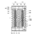
2つのセパレータ150,160は、MEA120および2つの拡散層130,140を挟む。アノード側セパレータ150とカソード側セパレータ160とには、複数の孔や凹部が形成されている。複数の孔や凹部は、内部通路210,220,230,240(図1)を形成する。具体的には、各セパレータの一対の孔は、複数のセルを積層したときに、複数のセルを貫くように設けられている。すなわち、各セパレータの一対の孔は、上流側のセル間通路と下流側のセル間通路とを形成する。また、各セパレータの凹部は、一対の孔間を接続するように設けられている。すなわち、各セパレータの凹部は、上流側のセル間通路と下流側のセル間通路との間で流体を流通可能とするセル内通路を形成する。
The two
より具体的には、各セパレータ150,160には、上流側および下流側のセル間燃料ガス通路210a,210cを構成する一対の孔と、上流側および下流側のセル間酸化ガス通路220a,220cを構成する一対の孔と、が形成されている。また、各セパレータ150,160には、上流側および下流側のセル間冷却液通路230a,230cを構成する一対の孔と、上流側および下流側のセル間冷却ガス通路240a,240cを構成する一対の孔と、が形成されている。
More specifically, each
図3は、カソード側セパレータ160を模式的に示す説明図である。図3(A),(B)は、それぞれ、図2に示すカソード側セパレータ160の第1の面Sc1と第2の面Sc2とを示している。図示するように、カソード側セパレータの第1の面Sc1には、セル内酸化ガス通路(カソード側通路)220bを構成する凹部が形成されている。また、第2の面Sc2には、セル内冷却液通路230bを構成する凹部と、セル内冷却ガス通路240bを構成する凹部と、が形成されている。なお、セル内冷却液通路230bを構成する凹部は、セル内酸化ガス通路220bを構成する凹部の上流側部分の背面に形成されており、セル内冷却ガス通路240bを構成する凹部は、セル内酸化ガス通路220bを構成する凹部の下流側部分の背面に形成されている。
FIG. 3 is an explanatory view schematically showing the
アノード側セパレータ150は、カソード側セパレータ160と同様である。ただし、アノード側セパレータの第1の面Sa1には、セル内燃料ガス通路(アノード側通路)を構成する凹部が形成されている。また、第2の面Sa2には、セル内冷却液通路230bを構成する凹部と、セル内冷却ガス通路240bを構成する凹部と、が形成されている。
The
なお、実際には、セル内ガス通路210b,220b,240bを構成する各凹部には、複数の凸部が設けられている。
In practice, a plurality of convex portions are provided in each concave portion constituting the in-
図4は、セル110の断面を模式的に示す説明図である。図示するように、セル内燃料ガス通路(アノード側通路)210bは、アノード側セパレータ150の第1の面Sa1に設けられた凹部とアノード側拡散層130との間に形成されており、セル内酸化ガス通路(カソード側通路)220bは、カソード側セパレータ160の第1の面Sc1に設けられた凹部とカソード側拡散層140との間に形成されている。また、セル内冷却液通路230bとセル内冷却ガス通路240bとは、2つのセパレータ150,160の第2の面Sa2,Sc2に設けられた凹部が組み合わされて形成されている。なお、上流側および下流側のセル間酸化ガス通路220a,220cは、各セパレータ150,160に設けられた一対の孔によって形成されている。
FIG. 4 is an explanatory diagram schematically showing a cross section of the
ところで、アノード側セパレータ150は、緻密質領域のみを含む部材である。一方、カソード側セパレータ160は、緻密質領域161と多孔質領域162とを含む複合部材である。なお、緻密質領域161と多孔質領域162とは、それぞれ、カソード側セパレータ160の第1の面Sc1側から第2の面Sc2側まで連続する。このため、カソード側セパレータ160の表面には、緻密質領域161と多孔質領域162との双方が現れる。なお、多孔質領域162は、図2,図3に示す領域Pに設けられている。
By the way, the anode-
2つのセパレータ150,160に含まれる緻密質領域は、比較的小さな気孔率を有しており、水およびガスを透過させない性質を有している。一方、カソード側セパレータ160に含まれる多孔質領域は、比較的大きな気孔率を有しており、水およびガスが透過可能な性質を有している。
The dense regions included in the two
なお、緻密質領域と多孔質領域とは、導電性材料を用いて形成される。具体的には、緻密質領域と多孔質領域とは、それぞれ、カーボン粉末とバインダとの混合物を圧縮成形して得られる緻密質部材と多孔質部材とを用いて形成される。なお、多孔質領域の気孔率は、カーボン粉末の形状やサイズ、カーボン粉末とバインダとの混合比率などを調整することによって変更可能である。カソード側セパレータ160は、例えば、個別に準備された緻密質部材と多孔質部材とを組み合わせ、バインダの溶融温度以上に加熱することによって、形成可能である。
Note that the dense region and the porous region are formed using a conductive material. Specifically, the dense region and the porous region are respectively formed using a dense member and a porous member obtained by compression molding a mixture of carbon powder and a binder. Note that the porosity of the porous region can be changed by adjusting the shape and size of the carbon powder, the mixing ratio of the carbon powder and the binder, and the like. The cathode-
上記のようなセパレータ150,160を用いれば、セル内冷却ガス通路240bに冷却ガス(空気)を供給することによって、スタックを冷却することができる。また、セル内冷却ガス通路240bに冷却ガス(空気)を供給することによって、カソード126で生成された水分を多孔質領域162を介して除去することができる。具体的には、カソード126で生成された水分は、カソード側拡散層140に蓄えられる。多孔質領域162は、毛管吸引力によって、カソード側拡散層140に蓄えられた水分を内部に取り込む。水分は、多孔質領域162内部を移動して、セル内冷却ガス通路240bを流れる冷却ガス(空気)中に排出される。
By using the
また、本実施例では、多孔質領域162は、セル内酸化ガス通路220bの下流側部分と、セル内冷却ガス通路240bと、の間に設けられているため、スタック内部で発生した水分を多孔質領域162を介して効率よく除去することができる。具体的には、スタック内部で発生した水分は、セル内酸化ガス通路220bを通る酸化ガス中に気化して、該酸化ガスと共に下流に向かう。このため、セル内酸化ガス通路220bでは、上流側部分の水分量が比較的少なく、下流側部分の水分量が比較的多い。したがって、セル内酸化ガス通路220bの下流側部分に多孔質領域162を設けることにより、スタック内部で発生した水分を多孔質領域162を介して効率よく除去することが可能となる。
In the present embodiment, since the
さらに、本実施例では、セル内冷却ガス通路240bを経由して加湿された酸化ガスが、セル内酸化ガス通路220bに供給されている。このため、加湿された酸化ガスは、水分量が比較的少ないセル内酸化ガス通路220bの上流側部分に、水分を与えることができ、該上流側部分の乾燥を抑制することができる。
Further, in this embodiment, the humidified oxidizing gas is supplied to the in-cell oxidizing
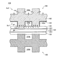
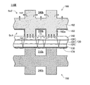
A−3.セルの具体的な構成:
図5は、第1参考例におけるセル110の具体的な構造を示す説明図である。図5では、図4に示すカソード側セパレータ160の多孔質領域(多孔質部)162付近が拡大して描かれている。なお、燃料電池スタックでは、複数のセルは、その両端に設けられた図示しない締付部材によって、両側から加圧される。このため、図示するように、拡散層130,140は、セパレータ150,160の凸部によって押圧されて変形している。このように、セルの積層方向に圧力を加えることによって、アノード124とアノード側セパレータ150との間、および、カソード126とカソード側セパレータ160との間の導電性を高めることができる。
A-3. Specific cell configuration:
FIG. 5 is an explanatory diagram showing a specific structure of the
図4で説明したように、カソード側セパレータ160は、緻密質部161と多孔質部162とを含んでいる。また、図5に示すように、カソード側セパレータ160は、緻密質層163を含んでいる。緻密質層163は、多孔質部162の第1の面Sc1側の凸部162aの頂面の周辺領域、より具体的には、凸部162aの側面と凸部162aの周囲の底面(すなわち凹部の底面)とに形成されている。
As described with reference to FIG. 4, the cathode-
なお、凸部162aの頂面は、カソード側拡散層140と接触する接触面であり、凸部162aの側面と凸部162aの周囲の底面とは、カソード側拡散層140と接触せずに、セル内酸化ガス通路220bの壁面を構成する通路形成面である。
The top surface of the
このように、凸部162aの頂面の周辺領域に緻密質層163を設ければ、緻密質層163が設けられない場合と比較して、カソード126で生成された水分をセル内冷却ガス通路240bへ効率よく排出することができる。すなわち、前述のように、カソード126で生成された水分は、カソード側拡散層140内に蓄えられる。また、カソード側拡散層140は、セル内酸化ガス通路220b中に気化した水分を捕獲して蓄える。多孔質部162は、カソード側拡散層140と接触する凸部162aの頂面を介して、カソード側拡散層内に蓄えられた水分を吸収する。そして、吸収された水分は、多孔質部162内部を移動し、セル内冷却ガス通路240b内に排出される。仮に、緻密質層163が設けられていない場合には、凸部162aの頂面を介して吸収された水分の一部は、凸部162aの頂面の周辺領域(凸部の側面および凸部の周囲の底面)を介して、セル内酸化ガス通路220b内に排出されてしまう。しかしながら、本実施例では、緻密質層163が設けられているため、吸収された水分が、凸部162aの頂面の周辺領域を介して、セル内酸化ガス通路220b内に排出されるのを抑制することができる。この結果、カソード126で生成された水分をセル内冷却ガス通路240bへ効率よく排出することができ、セル内酸化ガス通路220bにおけるフラッディング状態の発生を抑制することができる。
As described above, when the
また、本実施例では、緻密質層163が設けられているため、セル内冷却ガス通路240bを通る冷却ガス(空気)が、多孔質部162を介して、セル内酸化ガス通路220bへ侵入するのを抑制することができる。このため、カソード側セパレータ160の設計自由度を高めることができる。例えば、圧力損失が比較的大きな通路を有するカソード側セパレータや、多孔質部の気孔径が比較的大きなカソード側セパレータを利用することができる。また、多孔質部162を介した空気の侵入(漏れ)を抑制することによって、セル内冷却ガス通路240bおよびセル内酸化ガス通路220b内で空気を円滑に流通させることができるため、空気ブロワ402の消費電力を低減させることができる。
In this embodiment, since the
ところで、本実施例では、緻密質層163は、凸部162aの側面の一部の領域VFには形成されていない。具体的には、緻密質層163は、凸部162aの側面の一部を構成する凸部の頂面の近傍領域VFには形成されておらず、カソード側拡散層140から離れた領域に形成されている。この構成を採用することにより、緻密質層が凸部162aの側面の全体に形成される場合と比較して、スタックの出力特性を向上させることができる。すなわち、緻密質層が凸部162aの側面の全体に形成される場合には、酸素ガスは、凸部の頂面付近の電極反応場RFに供給され難く、該電極反応場RFに供給される酸素ガス量は比較的小さい。このため、カソードの濃度過電圧が大きくなり、この結果、スタックの出力電圧が低くなってしまう。一方、本実施例のように、緻密質層163が近傍領域VFに形成されていない場合には、酸素ガスは、近傍領域VFを介して、凸部の頂面付近の電極反応場RFへ供給され易く、該電極反応場RFに供給される酸素ガス量は比較的大きい。このため、カソードの濃度過電圧を比較的小さくすることができ、この結果、スタックの出力電圧の低下を抑制することが可能となる。
In the present embodiment, the
なお、本実施例では、前述のように、多孔質部162は、セル内酸化ガス通路220bの下流側部分に設けられているため、多孔質部162付近の酸素ガスの分圧は比較的低い。このため、近傍領域VFに緻密質層が形成されている場合には、酸素ガスは、特に、電極反応場RFに供給され難い。すなわち、本実施例のように、多孔質部162がセル内酸化ガス通路220bの下流側部分に設けられる場合には、近傍領域VFに緻密質層を形成しないことに伴う上記の効果は、顕著となる。
In this embodiment, as described above, since the
緻密質層163は、種々の方法で作製可能である。第1の製法では、多孔質部162の第1の面Sc1の全体に所定の混合液を塗布することによって、緻密質層が形成される。そして、凸部162aの頭部(頂面およびその近傍領域VF)に形成された一部の緻密質層が削り取られる。これにより、図5に示す緻密質層163が作製される。第2の製法では、多孔質部162の第1の面Sc1側の凸部162aの頭部(頂面およびその近傍領域VF)にマスクが形成される。その後、多孔質部162の第1の面Sc1に所定の混合液を塗布することによって、緻密質層が形成される。なお、マスクは、所定の混合液が塗布された後に、除去される。これにより、図5に示す緻密質層163が作製される。
The
なお、上記の所定の混合液としては、炭素材料とバインダとアルコールとを含む混合液を用いることができる。炭素材料としては、例えば、天然黒鉛や、鱗片状黒鉛、カーボンブラックを用いることができる。バインダとしては、変成スチレンブタジエンゴム(SBR)などのゴムバインダを用いることができる。また、塗布方法としては、エアレス塗装法やエア霧化塗装法を利用することができる。エア霧化塗装法は、エアレス塗装法よりも、噴霧の粒径を小さくすることができるので、より均一な緻密質層を形成可能である。 In addition, as said predetermined liquid mixture, the liquid mixture containing a carbon material, a binder, and alcohol can be used. As the carbon material, for example, natural graphite, scaly graphite, or carbon black can be used. As the binder, a rubber binder such as modified styrene butadiene rubber (SBR) can be used. As an application method, an airless coating method or an air atomization coating method can be used. In the air atomization coating method, since the particle size of the spray can be made smaller than that in the airless coating method, a more uniform dense layer can be formed.
以上説明したように、本実施例では、多孔質部162の凸部162aの頂面の周辺領域には、緻密質層163が形成されている。このため、カソードで生成されてカソード側拡散層140内に存在する水分が、凸部の頂面を介して多孔質部に吸収された後に、凸部の頂面の周辺領域を介して反応ガス通路内へ流出するのを抑制することができる。この結果、カソードで生成された水分をカソード側セパレータ160を介して効率よく除去することが可能となる。
As described above, in the present embodiment, the
なお、上記の説明から分かるように、本実施例における多孔質部162と緻密質層163とは、拡散層から水分を吸収して除去するための水分除去部として機能する。
As can be seen from the above description, the
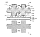
B.実施例:
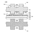
図6は、実施例におけるセル110Bの具体的な構造を示す説明図である。図6は、図5とほぼ同じであるが、セル110Bは、カソード側拡散層140とカソード側セパレータ160との間に設けられた撥水層171を備えている。撥水層171は、カソード側拡散層140上に形成されている。より具体的には、撥水層171は、多孔質部162に対応する矩形領域のうち、凸部162aの周囲の底面(すなわち凹部の底面)に対応する部分領域に形成されている。換言すれば、撥水層171は、多孔質部162の通路形成面に対応する部分領域に形成されている。撥水層171は、水分の透過を抑制しつつ、酸素ガスを透過させる機能を有している。
B. Real施例:
Figure 6 is an explanatory view showing a specific structure of the
撥水層171は、カソード側拡散層140上に撥水処理が施された撥水処理層であってもよいし、撥水処理層よりも高い撥水能力を有する撥水フィルムであってもよい。撥水処理層は、例えば、ポリテトラフルオロエチレン(PTFE)などの樹脂とカーボンとを混練したペースト状の混合材料を、スプレー法などを利用して、カソード側拡散層140上に塗布することによって作製される。また、撥水フィルムは、例えば、PTFEとカーボンとを含むフィルムである。撥水フィルムは、通常、ホットプレス法によって、カソード側拡散層140に接合される。
The
図6の構成を採用すれば、カソード126で生成された水分の一部が、カソード側拡散層140を介してセル内酸化ガス通路220b内へ移動するのを抑制することができ、この結果、多孔質部162は、凸部162aの頂面を介して水分を効率よく吸収することができる。
If the configuration of FIG. 6 is adopted, it is possible to suppress a part of moisture generated at the
C.第2参考例:
図7は、第2参考例におけるセル110Cの具体的な構造を示す説明図である。図7は、図6とほぼ同じであるが、撥水層172の配置が変更されている。具体的には、撥水層172は、カソード126とカソード側拡散層140との間に設けられている。また、撥水層172は、凸部162aの周囲の底面(すなわち凹部の底面)に対応する部分領域、換言すれば、多孔質部162の通路形成面に対応する部分領域に形成されている。
C. Second reference example:
FIG. 7 is an explanatory diagram showing a specific structure of the
なお、本実施例では、撥水層172は、撥水フィルムであるが、これに代えて、カソード側拡散層140上に撥水処理が施された撥水処理層であってもよい。
In this embodiment, the water-
図7の構成を採用すれば、カソード126で生成された水分がカソード側拡散層140の全体に拡散するのが抑制され、水分を凸部162aの頂面に対応する領域に選択的に集合させることができる。このため、カソード126で生成された水分の一部が、カソード側拡散層140を介して、セル内酸化ガス通路220b内へ移動するのを抑制することができ、この結果、多孔質部162は、凸部162aの頂面を介して水分を効率よく吸収することができる。
If the configuration of FIG. 7 is adopted, the moisture generated at the
D.第3参考例:
図8は、第3参考例におけるセル110Dの具体的な構造を示す説明図である。図8は、図6とほぼ同じであるが、撥水層173の配置および形状が変更されている。具体的には、図8では、撥水層173は、アノード124とアノード側拡散層130との間に設けられている。また、図8では、撥水層173は、アノード側拡散層130に対応する領域に形成されている。なお、撥水層173は、多孔質部162に対応する矩形領域のみに形成されていてもよい。
D. Third reference example:
FIG. 8 is an explanatory diagram showing a specific structure of the
なお、本実施例では、撥水層173は、撥水フィルムであるが、これに代えて、アノード側拡散層130上に撥水処理が施された撥水処理層であってもよい。
In this embodiment, the water-
図8の構成を採用すれば、カソード126で生成された水分が、電解質膜122を介して、セル内燃料ガス通路210bへ移動するのを抑制することができる。このため、多孔質部162は、凸部162aの頂面を介して水分を効率よく吸収することができる。また、セル内燃料ガス通路210b内におけるフラッディング状態の発生を防止することができる。
If the configuration of FIG. 8 is adopted, it is possible to suppress the movement of moisture generated at the
E.第4参考例:
図9は、第4参考例におけるセル110Eの具体的な構造を示す説明図である。図9は、図8とほぼ同じであるが、撥水層174の配置が変更されている。具体的には、図9では、撥水層174は、アノード側拡散層130とアノード側セパレータ150との間に設けられている。
E. Fourth reference example:
FIG. 9 is an explanatory diagram showing a specific structure of the
なお、本実施例では、撥水層174は、撥水フィルムであるが、これに代えて、アノード側拡散層130上に撥水処理が施された撥水処理層であってもよい。
In this embodiment, the water-
図9の構成を採用しても、カソード126で生成された水分が、電解質膜122を介して、セル内燃料ガス通路210bへ移動するのを抑制することができる。このため、多孔質部162は、凸部162aの頂面を介して水分を効率よく吸収することができる。また、セル内燃料ガス通路210b内におけるフラッディング状態の発生を防止することができる。
Even if the configuration of FIG. 9 is adopted, it is possible to suppress the movement of moisture generated at the
F.第5参考例:
図10は、第5参考例におけるセル110Fの具体的な構造を示す説明図である。図10は、図5とほぼ同じであるが、多孔質部162Fが変更されている。
F. Fifth reference example:
FIG. 10 is an explanatory diagram showing a specific structure of the
具体的には、多孔質部162Fの第1の面Sc1側の凸部162aの頂面には、親水処理が施された第1の親水処理層HL1が形成されている。また、多孔質部162Fの内部には、撥水処理が施された撥水処理領域RAが形成されている。そして、多孔質部162Fの第2の面Sc2側の表面には、親水処理が施された第2の親水処理層HL2が形成されている。
Specifically, a first hydrophilic treatment layer HL1 subjected to a hydrophilic treatment is formed on the top surface of the
多孔質部162Fは、例えば、以下の方法で作製可能である。まず、多孔質部を、ポリテトラフルオロエチレン(PTFE)を含む溶液に含浸させる。これにより、多孔質部に撥水処理が施される。次に、撥水処理済みの多孔質部の第1の面Sc1側の凸部162aの頂面に、ナフィオン液とカーボンとを含む混合液が塗布される。これにより、第1の面Sc1側の凸部162aの頂面に親水処理が施される。また、撥水処理済みの多孔質部の第2の面Sc2の表面に、ナフィオン液とカーボンとを含む混合液が塗布される。これにより、第2の面Sc2の表面に親水処理が施される。
The
なお、本実施例では、多孔質部の第2の面Sc2側の表面全体に親水処理層HL2が形成されている。しかしながら、第2の面Sc2側の凸部162bの頂面は、緻密質のアノード側セパレータ150の凸部と接触する。このため、凸部162bの頂面には、親水処理層は形成されていなくてもよい。この場合には、例えば、凸部162bの頂面に形成された一部の親水処理層を削り取ればよい。あるいは、凸部162bの頂面にマスクを形成した後に、親水処理を施せばよい。
In the present embodiment, the hydrophilic treatment layer HL2 is formed on the entire surface of the porous portion on the second surface Sc2 side. However, the top surface of the
図10の構成を採用すれば、多孔質部162Fは、カソード126で生成された水分をセル内冷却ガス通路240bへ効率よく排出することができる。具体的には、第1の面Sc1側の凸部162aの頂面には第1の親水処理層HL1が形成されているため、多孔質部162Fは、凸部162aの頂面を介して、水分を効率よく吸収することができる。また、多孔質部162Fの内部には撥水処理領域RAが形成されているため、多孔質部162Fは、吸収した水分を速やかに第2の面Sc2側へ移動させることができる。さらに、多孔質部162Fの第2の面Sc2には第2の親水処理層HL2が形成されているため、多孔質部162Fは、水分をセル内冷却ガス通路240b内へ効率よく放出することができる。
If the configuration of FIG. 10 is adopted, the
なお、本実施例では、多孔質部162Fは、2つの親水処理層HL1,HL2と撥水処理領域RAとを備えているが、これに代えて、これらのうちの少なくとも1つを備えるようにしてもよい。例えば、多孔質部は、第1の親水処理層HL1のみを備えるようにしてもよいし、第1の親水処理層HL1と撥水処理領域RAとを備えるようにしてもよい。
In the present embodiment, the
なお、この発明は上記の実施例や実施形態に限られるものではなく、その要旨を逸脱しない範囲において種々の態様で実施することが可能であり、例えば次のような変形も可能である。 In addition, this invention is not restricted to said Example and embodiment, In the range which does not deviate from the summary, it can be implemented in a various aspect, For example, the following deformation | transformation is also possible.
(1)上記実施例では、各セパレータの成形材料は、カーボン粉末とバインダとを含んでいるが、他の成形材料を利用してもよい。例えば、成形材料は、金属材料(金属粉末)とバインダとを含んでいてもよい。また、各セパレータを構成する緻密質領域は、金属部材であってもよい。さらに、緻密質層に代えて、金属層が利用されてもよい。 (1) In the above embodiment, the molding material for each separator contains carbon powder and a binder, but other molding materials may be used. For example, the molding material may include a metal material (metal powder) and a binder. Further, the dense region constituting each separator may be a metal member. Furthermore, a metal layer may be used instead of the dense layer.
(2)上記実施例では、多孔質部は、凸部が略矩形の断面形状を有する凹凸面を備えているが、これに代えて、凸部が波形(すなわち山形)の断面形状を有する凹凸面を備えていてもよい。 (2) In the above embodiment, the porous portion has an uneven surface in which the convex portion has a substantially rectangular cross-sectional shape. A surface may be provided.
一般には、多孔質部は、一方の側に、カソード拡散層に接触する接触面と、カソード拡散層に接触せずにセル内酸化ガス通路を形成する通路形成面と、を有していればよい。 In general, if the porous portion has, on one side, a contact surface that contacts the cathode diffusion layer, and a passage formation surface that forms an in-cell oxidizing gas passage without contacting the cathode diffusion layer. Good.
(3)上記実施例では、緻密質層163は、凸部162aの側面と凸部162aの周囲の底面との双方に形成されているが、緻密質層163は、いずれか一方の面のみに形成されてもよい。ただし、凸部162aの側面のみに緻密質層が形成される場合には、凸部162aの周囲の底面のみに緻密質層が形成される場合よりも、吸収された水分がセル内酸化ガス通路220b内へ流出するのを抑制することができると考えられる。したがって、緻密質層は、少なくとも凸部の側面に形成されていることが望ましい。
(3) In the above embodiment, the
また、上記実施例では、緻密質層163は、凸部162aの頂面の近傍領域VFには形成されていないが、緻密質層は、該近傍領域VFに形成されてもよい。ただし、上記実施例の構成を採用すれば、前述したように、スタックの出力電圧の低下を抑制することができるという利点がある。
Moreover, in the said Example, although the
さらに、上記実施例では、緻密質層163が利用されているが、これに代えて、緻密質ではないが多孔質部よりも小さな気孔率を有する層が利用されてもよい。この場合にも、水分が凸部の頂面の周辺領域からセル内酸化ガス通路内へ流出するのを抑制することができる。ただし、上記実施例の構成を採用すれば、水分が凸部の頂面の周辺領域から流出するのを確実に抑制することができるという利点がある。
Furthermore, in the said Example, although the
一般には、多孔質部の一方の面に形成される表層は、通路形成面の少なくとも一部の領域に形成され、多孔質部よりも小さな気孔率を有していればよい。 In general, the surface layer formed on one surface of the porous portion may be formed in at least a partial region of the passage forming surface and have a smaller porosity than the porous portion.
(4)上記実施例では、カソード側セパレータが、多孔質部と表層とを備えているが、これに代えて、あるいは、これと共に、アノード側セパレータが多孔質部と表層とを備えるようにしてもよい。 (4) In the above embodiment, the cathode side separator has a porous portion and a surface layer. Instead of or in addition to this, the anode side separator has a porous portion and a surface layer. Also good.
一般には、セパレータは、多孔質部と表層とを備え、ガス拡散層に存在する水分を吸収して除去すればよい。 In general, the separator has a porous portion and a surface layer, and absorbs and removes moisture present in the gas diffusion layer.
(5)上記実施例では、セルの種々の構成を説明したが、これらの構成のうちの2以上を任意に組み合わせたセルを利用することも可能である。 (5) Although the various configurations of the cell have been described in the above embodiment, a cell in which two or more of these configurations are arbitrarily combined can be used.
100…燃料電池スタック
110,B,C,D,E,F…セル
120…MEA
122…電解質膜
124…電極層(アノード)
126…電極層(カソード)
130…アノード側拡散層
140…カソード側拡散層
150…アノード側セパレータ
160…カソード側セパレータ
161…緻密質領域(緻密質部)
162,F…多孔質領域(多孔質部)
162a…凸部
162b…凸部
163…緻密質層
171〜174…撥水層
210…内部燃料ガス通路
210a,210c…セル間燃料ガス通路
210b…セル内燃料ガス通路(アノード側通路)
220…内部酸化ガス通路
220a,220c…セル間酸化ガス通路
220b…セル内酸化ガス通路(カソード側通路)
230…内部冷却液通路
230a,230c…セル間冷却液通路
230b…セル内冷却液通路
240…内部冷却ガス通路
240a,240c…セル間冷却ガス通路
240b…セル内冷却ガス通路
302…水素タンク
304…減圧弁
306…流量制御弁
310…燃料ガス通路
390…燃料オフガス通路
392…遮断弁
402…空気ブロワ
410,420…外部空気通路
490…酸化オフガス通路
502…循環ポンプ
504…熱交換器
510…循環通路
600…コントローラ
100 ...
122 ...
126 ... Electrode layer (cathode)
DESCRIPTION OF
162, F ... porous region (porous portion)
162a ...
220 ... Internal oxidizing
230 ...
Claims (12)
電解質層と、
前記電解質層の一方の側に設けられた第1の電極層と、
前記電解質層の前記一方の側に設けられた第1のガス拡散層であって、前記第1のガス拡散層と前記電解質層との間には、前記第1の電極層が設けられている、前記第1のガス拡散層と、
前記電解質層の前記一方の側に設けられた第1のセパレータであって、前記第1のセパレータと前記第1の電極層との間には、前記第1のガス拡散層が設けられており、前記第1のセパレータの第1の側には、前記第1のガス拡散層を介して前記第1の電極層に反応ガスを供給するための反応ガス通路が形成されている、前記第1のセパレータと、
を備え、
前記第1のセパレータは、
前記第1の側に、前記第1のガス拡散層に接触する接触面と、前記第1のガス拡散層に接触せずに前記反応ガス通路を形成する通路形成面と、を有する多孔質部と、
前記通路形成面に形成され、前記多孔質部よりも小さな気孔率を有する表層と、
を備え、
前記燃料電池は、さらに、前記第1のガス拡散層上の前記通路形成面に対応する第1の部分領域であって、前記第1のガス拡散層と前記第1のセパレータとの間の前記第1の部分領域に設けられた第1の撥水層を備えることを特徴とする燃料電池。 A fuel cell,
An electrolyte layer;
A first electrode layer provided on one side of the electrolyte layer;
A first gas diffusion layer provided on the one side of the electrolyte layer, wherein the first electrode layer is provided between the first gas diffusion layer and the electrolyte layer. The first gas diffusion layer;
A first separator provided on the one side of the electrolyte layer, wherein the first gas diffusion layer is provided between the first separator and the first electrode layer. The first side of the first separator is formed with a reaction gas passage for supplying a reaction gas to the first electrode layer through the first gas diffusion layer. A separator of
With
The first separator is
A porous part having a contact surface in contact with the first gas diffusion layer on the first side and a passage forming surface that forms the reaction gas passage without contacting the first gas diffusion layer. When,
A surface layer formed on the passage forming surface and having a porosity smaller than that of the porous portion;
With
The fuel cell is further a first partial region corresponding to the passage forming surface on the first gas diffusion layer, and the fuel cell is located between the first gas diffusion layer and the first separator. A fuel cell comprising a first water-repellent layer provided in the first partial region.
前記表層は、緻密質層である、燃料電池。 The fuel cell according to claim 1, wherein
The fuel cell according to claim 1, wherein the surface layer is a dense layer.
前記表層が形成される前記通路形成面上の領域は、前記第1のガス拡散層から離れた領域である、燃料電池。 The fuel cell according to claim 1 or 2,
The realm on the passage-forming surface the surface layer is formed is a region remote from said first gas diffusion layer, a fuel cell.
前記第1の電極層と前記第1のガス拡散層との間の前記通路形成面に対応する第2の部分領域に設けられた第2の撥水層を備える、燃料電池。 The fuel cell according to any one of claims 1 to 3, further comprising:
A fuel cell comprising a second water-repellent layer provided in a second partial region corresponding to the passage forming surface between the first electrode layer and the first gas diffusion layer.
前記接触面には、親水処理が施されている、燃料電池。 A fuel cell according to any one of claims 1 to 4,
The fuel cell, wherein the contact surface is subjected to a hydrophilic treatment.
前記多孔質部の内部には、撥水処理が施されている、燃料電池。 A fuel cell according to any one of claims 1 to 5,
A fuel cell in which a water repellent treatment is performed inside the porous portion.
前記多孔質部の第2の側の表面には、親水処理が施されている、燃料電池。 The fuel cell according to any one of claims 1 to 6,
A fuel cell, wherein a surface on the second side of the porous portion is subjected to a hydrophilic treatment.
前記電解質層の他方の側に設けられた第2の電極層と、
前記電解質層の前記他方の側に設けられた第2のガス拡散層であって、前記第2のガス拡散層と前記電解質層との間には、前記第2の電極層が設けられている、前記第2のガス拡散層と、
前記第2の電極層と前記第2のガス拡散層との間に設けられた第3の撥水層と、
を備える、燃料電池。 The fuel cell according to any one of claims 1 to 7, further comprising:
A second electrode layer provided on the other side of the electrolyte layer;
A second gas diffusion layer provided on the other side of the electrolyte layer, wherein the second electrode layer is provided between the second gas diffusion layer and the electrolyte layer. The second gas diffusion layer;
A third water-repellent layer provided between the second electrode layer and the second gas diffusion layer;
A fuel cell comprising:
前記電解質層の他方の側に設けられた第2の電極層と、
前記電解質層の前記他方の側に設けられ第2のガス拡散層であって、前記第2のガス拡散層と前記電解質層との間には、前記第2の電極層が設けられている、前記第2のガス拡散層と、
前記電解質層の前記他方の側に設けられた第2のセパレータであって、前記第2のセパレータと前記第2の電極層との間には、前記第2のガス拡散層が設けられている、前記第2のセパレータと、
前記第2のガス拡散層と前記第2のセパレータとの間に設けられた第4の撥水層と、
を備える、燃料電池。 The fuel cell according to any one of claims 1 to 7, further comprising:
A second electrode layer provided on the other side of the electrolyte layer;
A second gas diffusion layer provided on the other side of the electrolyte layer, wherein the second electrode layer is provided between the second gas diffusion layer and the electrolyte layer; The second gas diffusion layer;
A second separator provided on the other side of the electrolyte layer, wherein the second gas diffusion layer is provided between the second separator and the second electrode layer. The second separator;
A fourth water repellent layer provided between the second gas diffusion layer and the second separator;
A fuel cell comprising:
前記多孔質部は、前記反応ガス通路の下流側の部位に配置されている、燃料電池。 The fuel cell according to any one of claims 1 to 9,
The porous part is a fuel cell, which is disposed at a site downstream of the reaction gas passage.
前記反応ガスは、空気である、燃料電池。 The fuel cell according to any one of claims 1 to 10,
The fuel cell, wherein the reaction gas is air.
前記多孔質部の第2の側には、冷却ガスが通る冷却ガス通路が形成されており、
前記冷却ガス通路内には、空気が供給され、
前記燃料電池は、さらに、
前記冷却ガス通路を経由した空気を、前記反応ガス通路に供給するための供給通路を備える、燃料電池。 The fuel cell according to any one of claims 1 to 11,
A cooling gas passage through which a cooling gas passes is formed on the second side of the porous portion,
Air is supplied into the cooling gas passage,
The fuel cell further includes:
A fuel cell comprising a supply passage for supplying air that has passed through the cooling gas passage to the reaction gas passage.
Priority Applications (1)
| Application Number | Priority Date | Filing Date | Title |
|---|---|---|---|
| JP2004091168A JP4635462B2 (en) | 2004-03-26 | 2004-03-26 | Fuel cell with porous separator |
Applications Claiming Priority (1)
| Application Number | Priority Date | Filing Date | Title |
|---|---|---|---|
| JP2004091168A JP4635462B2 (en) | 2004-03-26 | 2004-03-26 | Fuel cell with porous separator |
Publications (2)
| Publication Number | Publication Date |
|---|---|
| JP2005276731A JP2005276731A (en) | 2005-10-06 |
| JP4635462B2 true JP4635462B2 (en) | 2011-02-23 |
Family
ID=35176150
Family Applications (1)
| Application Number | Title | Priority Date | Filing Date |
|---|---|---|---|
| JP2004091168A Expired - Fee Related JP4635462B2 (en) | 2004-03-26 | 2004-03-26 | Fuel cell with porous separator |
Country Status (1)
| Country | Link |
|---|---|
| JP (1) | JP4635462B2 (en) |
Families Citing this family (5)
| Publication number | Priority date | Publication date | Assignee | Title |
|---|---|---|---|---|
| JP5422992B2 (en) * | 2008-12-24 | 2014-02-19 | トヨタ自動車株式会社 | Fuel cell |
| JP5051203B2 (en) * | 2009-03-24 | 2012-10-17 | 大日本印刷株式会社 | Membrane-electrode assembly of fuel cell, transfer sheet for electrode production, and production method thereof |
| JP5474691B2 (en) * | 2010-07-21 | 2014-04-16 | 日本特殊陶業株式会社 | Manufacturing method of fuel cell stack |
| US9178236B2 (en) | 2011-08-02 | 2015-11-03 | Panasonic Intellectual Property Management Co., Ltd. | Polymer electrolyte fuel cell |
| CN120727887A (en) * | 2024-03-27 | 2025-09-30 | 罗伯特·博世有限公司 | Fuel cell membrane electrode, fuel cell and electrical equipment having the same |
Family Cites Families (4)
| Publication number | Priority date | Publication date | Assignee | Title |
|---|---|---|---|---|
| JPH08130025A (en) * | 1994-10-28 | 1996-05-21 | Toyota Motor Corp | Fuel cell |
| JPH08138691A (en) * | 1994-11-04 | 1996-05-31 | Yamaha Motor Co Ltd | Fuel cell |
| JP2003109603A (en) * | 2001-09-27 | 2003-04-11 | Matsushita Electric Ind Co Ltd | Polymer electrolyte fuel cell |
| JP2003142121A (en) * | 2001-11-01 | 2003-05-16 | Matsushita Electric Ind Co Ltd | Polymer electrolyte fuel cell |
-
2004
- 2004-03-26 JP JP2004091168A patent/JP4635462B2/en not_active Expired - Fee Related
Also Published As
| Publication number | Publication date |
|---|---|
| JP2005276731A (en) | 2005-10-06 |
Similar Documents
| Publication | Publication Date | Title |
|---|---|---|
| WO2001017047A9 (en) | Polymer electrolyte type fuel cell | |
| JP4086894B2 (en) | Fuel cell | |
| WO2007083838A1 (en) | Fuel cell | |
| KR102084568B1 (en) | Component for fuel cell including graphene foam and functioning as flow field and gas diffusion layer | |
| EP1844509A1 (en) | Multi-layer fuel cell diffuser | |
| JP2011192617A (en) | Solid polymer fuel cell | |
| JP5124900B2 (en) | Fuel cell having a stack structure | |
| JP5153159B2 (en) | Fuel cell | |
| JP5364980B2 (en) | Fuel cell | |
| JP4635462B2 (en) | Fuel cell with porous separator | |
| JP2005197150A (en) | Fuel cell | |
| JP4923386B2 (en) | Fuel cell with porous separator | |
| WO2006057155A1 (en) | Fuel cell | |
| US20110086288A1 (en) | Fuel cell structure with porous metal plate | |
| JP2007311089A (en) | Fuel cell separator | |
| JP5341321B2 (en) | Electrolyte membrane / electrode structure for polymer electrolyte fuel cells | |
| JP4923387B2 (en) | Fuel cell with porous separator | |
| JP5352228B2 (en) | Fuel cell | |
| JP2008027810A (en) | Fuel cell, membrane-electrode assembly for fuel cell, and method for producing fuel cell | |
| JP4635465B2 (en) | Fuel cell and gas separator for fuel cell | |
| JP2009048905A (en) | Fuel cell | |
| JP2009080943A (en) | Fuel cell separator and fuel cell | |
| JP2009043623A (en) | Fuel cell | |
| JP2009218190A (en) | Fuel cell | |
| JP5130686B2 (en) | Fuel cell |
Legal Events
| Date | Code | Title | Description |
|---|---|---|---|
| A621 | Written request for application examination |
Free format text: JAPANESE INTERMEDIATE CODE: A621 Effective date: 20060607 |
|
| A977 | Report on retrieval |
Free format text: JAPANESE INTERMEDIATE CODE: A971007 Effective date: 20090116 |
|
| A131 | Notification of reasons for refusal |
Free format text: JAPANESE INTERMEDIATE CODE: A131 Effective date: 20090421 |
|
| A521 | Request for written amendment filed |
Free format text: JAPANESE INTERMEDIATE CODE: A523 Effective date: 20090605 |
|
| A131 | Notification of reasons for refusal |
Free format text: JAPANESE INTERMEDIATE CODE: A131 Effective date: 20100824 |
|
| A521 | Request for written amendment filed |
Free format text: JAPANESE INTERMEDIATE CODE: A523 Effective date: 20101004 |
|
| TRDD | Decision of grant or rejection written | ||
| A01 | Written decision to grant a patent or to grant a registration (utility model) |
Free format text: JAPANESE INTERMEDIATE CODE: A01 Effective date: 20101026 |
|
| A01 | Written decision to grant a patent or to grant a registration (utility model) |
Free format text: JAPANESE INTERMEDIATE CODE: A01 |
|
| A61 | First payment of annual fees (during grant procedure) |
Free format text: JAPANESE INTERMEDIATE CODE: A61 Effective date: 20101108 |
|
| FPAY | Renewal fee payment (event date is renewal date of database) |
Free format text: PAYMENT UNTIL: 20131203 Year of fee payment: 3 |
|
| FPAY | Renewal fee payment (event date is renewal date of database) |
Free format text: PAYMENT UNTIL: 20131203 Year of fee payment: 3 |
|
| LAPS | Cancellation because of no payment of annual fees |