JP4635408B2 - Suction filter - Google Patents
Suction filter Download PDFInfo
- Publication number
- JP4635408B2 JP4635408B2 JP2003085407A JP2003085407A JP4635408B2 JP 4635408 B2 JP4635408 B2 JP 4635408B2 JP 2003085407 A JP2003085407 A JP 2003085407A JP 2003085407 A JP2003085407 A JP 2003085407A JP 4635408 B2 JP4635408 B2 JP 4635408B2
- Authority
- JP
- Japan
- Prior art keywords
- filter element
- room
- filter
- opening
- suction
- Prior art date
- Legal status (The legal status is an assumption and is not a legal conclusion. Google has not performed a legal analysis and makes no representation as to the accuracy of the status listed.)
- Expired - Fee Related
Links
Images
Landscapes
- Structures Of Non-Positive Displacement Pumps (AREA)
- Filtering Of Dispersed Particles In Gases (AREA)
Description
【0001】
【発明の属する技術分野】
本発明は圧縮機の吸入ラインの吸入側に設けられる吸入フィルタに関するものである。
【0002】
【従来の技術】
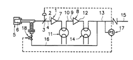
たとえば、ターボ圧縮機のうち、2段式のターボ圧縮機は、図3に一例の概要を示す如き構成のものが提案されている。すなわち、第1段圧縮機1の吸入口2には、途中に吸入弁3を有する吸入ライン4を接続してあって、該吸入ライン4の吸入側となる一端側に、ダスト等の異物を取り除くフィルタエレメント6を備えた吸入フィルタ5が取り付けてあり、第1段圧縮機1の吐出口7と第2段圧縮機8の吸入口9とを結ぶライン10には、第2段圧縮機8に入る圧縮空気を冷却して体積を収縮させるべくインタークーラ11が設けてある。更に、第2段圧縮機8の吐出口12に接続した吐出ライン13には、アフタークーラ14が設けてあり、該アフタークーラ14の下流側は、圧縮空気供給ライン15と放風ライン16とに分岐されていて、該分岐個所よりも下流側となる吐出ライン13に取り付けた圧力スイッチ17により、上記吸入弁3と、放風ライン16に設けた放風弁18の各開閉を制御するようにしたものが提案されている(特許文献1参照)。
【0003】
上記特許文献1に開示されている如く、従来のターボ圧縮機に用いられている吸入フィルタ5は、図4に示す如く、吸入部20を有するケーシング19と、該ケーシング19の中央部に設けてあって、吸入ライン4に連通させられる吐出部21と、該吐出部21に連通するよう外周に開口部を有する大口径のフィルタエレメント取付部22と、該フィルタエレメント取付部22の外側に嵌合して取り付けてある大型の筒形状のフィルタエレメント6とからなる構成としてあり、ケーシング19の一部に開口した吸入部20から吸入した空気を、フィルタエレメント6を通して吸い込んで吐出部21へ導くようにし、この間に空気中のダスト等の異物を除去するようにしてある。
【0004】
【特許文献1】
特開平8−121398号公報
【0005】
【発明が解決しようとする課題】
ところが、上記従来の吸入フィルタ5は、1つの吐出部21に対し、図示の如くフィルタエレメント6が1本の場合がほとんどであるため、圧縮機運転中にフィルタエレメント6に目詰り等が生じて交換の必要が生じた際に、圧縮機の運転を停止できればよいが、圧縮機の運転中に1本のフィルタエレメント6の交換を余儀なくされる場合がある。かかる場合には、1本のフィルタエレメント6の交換に際してフィルタエレメント6を取り外すと、空気の吸い込みを継続する必要上、該取り外されたフィルタエレメント取付部22の開口部をカバーで塞ぐことができないため、フィルタエレメント取付部22の開口部を通って多くの空気が吸い込まれることになる。そのため、本来、フィルタエレメント6で取り除かれるべきダスト等の異物が、フィルタエレメント交換中は除去されないことになって、多くの異物を吸い込むおそれがある。又、フィルタエレメント6は大型で且つ取扱いが難しいために、交換作業時にクレーン等の使用が必要となる等、交換作業に多くの時間と労力を必要としていた。
【0006】
そこで、本発明は、圧縮機の運転中にフィルタエレメントを交換するときでも、多くの異物を吸い込むおそれを低減もしくはなくすと共に、交換作業を簡単に且つ短時間に行うことができるようにしようとするものである。
【0007】
【課題を解決するための手段】
本発明は、上記課題を解決するために、前後方向の一側に吸入部と吐出部を有するケーシングの内側中央部に、密閉構造とした矩形状の部屋を設けて、該ケーシングの内部を部屋の内側と外側とに区画し、上記部屋の左右方向の両側面に複数個の開口を設け、且つ該部屋の各開口部の外側面に、外周部にフィルタエレメントを取外し可能に嵌合して取り付けている複数個のフィルタエレメント取付部を、左右方向へ水平状態に突出するように個別に取り付けて備えて、該各フィルタエレメントを通して吸い込まれた空気のみをフィルタエレメント取付部内から上記部屋の左右方向両側面の開口を通して該部屋内に導くようにし、更に、上記部屋の前後方向の一側に、吐出部に連通させるための開口を設けて、該部屋に導かれた空気を該開口を経て吐出部へ導くようにした構成とする。これにより、フィルタエレメントを交換するとき、1つのフィルタエレメントの交換を行っても他のフィルタエレメントで空気の吸い込みを行わせることができる。又、交換中の1つのフィルタエレメント取付部で吸い込む空気量を少なくすることができるので、異物の吸い込み確率を低くすることができる。この際、フィルタエレメントを取り外したフィルタエレメント取付部の開口部を塞ぐようにしても、全体の抵抗値は小さく圧縮機の運転に与える影響は少なく、該開口部を塞ぐようにすれば、当該フィルタエレメントを外したフィルタエレメント取付部を通して異物を吸い込むことがなくなる。
【0008】
又、上記構成としてあることにより、部屋の両側のフィルタエレメントを多数本とすることが可能となり、このことから、1本1本のフィルタエレメントを小さくすることができるため、フィルタエレメント取付部の開口部面積をより小さくすることができることになり、これに伴いフィルタエレメント交換時の異物の吸い込み確率をより低下させることが可能となる。
【0009】
更に、ケーシングの左右方向の両側部に、複数個のフィルタエレメント取付部の外周部に取外し可能に嵌合して取り付けてあるフィルタエレメントの設置領域に対応する大きさの窓を設け、且つ該窓に密閉式の蓋を開閉可能に取り付けるようにした構成とする。1本1本のフィルタエレメントの交換を窓を通して容易に行うことができることになる。
【0010】
【発明の実施の形態】
以下、本発明の実施の形態を図面を参照して説明する。
【0011】
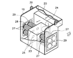
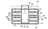
図1及び図2は本発明の実施の一形態を示すもので、吸入部20と吐出部21を有するケーシング19内の中央部に、所要の厚さ及び高さを有する密閉構造とした部屋23を設けて、該ケーシング19の内側を、部屋23の内側と外側に区画するようにする。上記ケーシング19内に設置した部屋23の前後方向の一側に、吐出部21に連通させるための開口24を設けると共に、該部屋23の前後方向と直交する厚み方向となる左右の両側面に、部屋23の外側に取り付けるフィルタエレメント取付部26と連通させる開口25を各々4個設け、該各開口25部の外側面に、円筒状としてあって周方向に開口部を有する小径のフィルタエレメント取付部26を、左右方向へ水平状態に突出するように取り付ける。上記各フィルタエレメント取付部26の外周部に、円筒状とした小径のフィルタエレメント27を各々取外し可能に嵌合して取り付け、上記吸入部20から流入した空気が部屋23の外側で左右に分かれてから各フィルタエレメント27より吸い込まれて、フィルタエレメント取付部26内を通り各開口25より部屋23内に入り、該部屋23から開口24を経て吐出部21へ至り、ここから吸入ライン4(図3参照)へ送られるようにした構成とする。
【0012】
更に、上記ケーシング19の左右両側壁に4本のフィルタエレメント27の設置領域よりも大きい窓28を設け、該窓28に密閉式の蓋29を開閉可能に取り付けるようにしてある。
【0013】
30は本発明の吸入フィルタを取り扱うときの吊ピースである。
【0014】
図3に示す如き圧縮機の運転中は、本発明の吸入フィルタ5の吸入部20から流入する空気を、左右合計8個のフィルタエレメント27を個別に通すことによりダスト等の異物を取り除くようにしてから部屋23の内部へ導入し、しかる後、清浄化された空気を開口24より吐出部21を経て圧縮機側へ流すようにする。これにより第1段圧縮機1には異物が混入していない空気が導入されることになる。この際、8本のフィルタエレメント27は、左右両側に4本組として配してあり、吸入部20から流入した空気を左右の片側で4本のフィルタエレメント27により一斉に吸い込まれるようになるので、1個所に8本のフィルタエレメント27が集中して配置するようにした場合に比して空気の吸入抵抗を減らすことができる。
【0015】
圧縮機の運転中にフィルタエレメント27の交換の必要が生じた場合には、同時にすべてのフィルタエレメント27を交換することなく、交換の必要なフィルタエレメント27を1本ずつ単独に取り外して新しいフィルタエレメント27に交換するようにする。この場合は、交換を必要とするフィルタエレメント27をフィルタエレメント取付部26から取り外すようにする。この際、交換を必要とするフィルタエレメント27が存在している側の蓋29を開けて窓28の外から目的のフィルタエレメント27をフィルタエレメント取付部26より取り外すようにするので、容易に取り外すことができる。次に、このフィルタエレメント27を取り外したフィルタエレメント取付部26に、新しいフィルタエレメント27又は補修し終えたフィルタエレメント27を取り付けることにより1つのフィルタエレメント27の交換を行うことができる。
【0016】
上記において、フィルタエレメント27が取り外されたフィルタエレメント取付部26には、該フィルタエレメント取付部26の開口部を覆うようにするカバーを取り付けておくようにすることができ、又、カバーを取り付けることなくそのままにしておくようにすることもできる。
【0017】
フィルタエレメント27を取り外したところのフィルタエレメント取付部26にカバーをしないでおく場合には、交換を必要とするフィルタエレメント27を取り外して、ケーシング19の窓28より取り出した後は、新たなフィルタエレメント27を当該フィルタエレメント取付部26への取付け作業に入るまでは上記窓28を蓋29で閉じておくようにする。これにより吸い込まれる空気の一部は、フィルタエレメント27のないフィルタエレメント取付部26に吸い込まれることになるが、1つひとつのフィルタエレメント取付部26の開口部面積は小さくしてあるので、ここを流れる空気量を少なくすることができて、異物の吸い込み確率を低下させることができる。又、必要に応じて各開口25の部分にダスト除去物を取り付けるようにすることもできる。
【0018】
一方、フィルタエレメント27を取り外したフィルタエレメント取付部26の開口部をカバーで覆い空気の吸い込みを防止するようにしておくと、当該フィルタエレメント取付部26では空気の吸い込みが行われないので、異物の吸い込みを未然に防止することができる。この際、ケーシング19に吸い込まれた空気は、他の7本のフィルタエレメント27を通して吸い込まれるので、空気の吸い込みに支障を来たすようなことはない。
【0019】
又、本発明の吸入フィルタ5においては、フィルタエレメント27を小径の8本に分割して複数個所に配設した構成としてあるので、個々のフィルタエレメント27の重量を軽くでき且つ取り扱いが容易となるように小型化することができて、クレーン等の大型機械を用いることなく、手作業で容易に交換作業を行うことができる。
【0020】
なお、本発明は上記実施の形態にのみ限定されるものではなく、たとえば、左右4本、合計8本のフィルタエレメント27を備えた場合を示したが、8本に限られることなく、任意の本数とすることができること、各フィルタエレメント27の径は等しいものとして示してあるが、異径のフィルタエレメントの組み合わせとしてもよいこと、その他本発明の要旨を逸脱しない範囲内において種々の変更を加え得ることは勿論である。
【0021】
【発明の効果】
以上述べた如く、本発明の吸入フィルタによれば、次の如き優れた効果を奏し得る。
(1)前後方向の一側に吸入部と吐出部を有するケーシングの内側中央部に、密閉構造とした矩形状の部屋を設けて、該ケーシングの内部を部屋の内側と外側とに区画し、上記部屋の左右方向の両側面に複数個の開口を設け、且つ該部屋の各開口部の外側面に、外周部にフィルタエレメントを取外し可能に嵌合して取り付けている複数個のフィルタエレメント取付部を、左右方向へ水平状態に突出するように個別に取り付けて備えて、該各フィルタエレメントを通して吸い込まれた空気のみをフィルタエレメント取付部内から上記部屋の左右方向両側面の開口を通して該部屋内に導くようにし、更に、上記部屋の前後方向の一側に、吐出部に連通させるための開口を設けて、該部屋に導かれた空気を該開口を経て吐出部へ導くようにした構成としてあるので、空気吸い込み中にフィルタエレメントを交換するとき、一部のフィルタエレメントを交換して他のフィルタエレメントを残して空気の吸い込みを行わせることができ、これに伴い交換中の1つのフィルタエレメント取付部で吸い込む空気量を少なくすることができて、異物の吸い込み確率を低下させることができる。
(2)上記(1)において、フィルタエレメントが取り外されたフィルタエレメント取付部の開口部をカバーで塞ぐようにすると、当該フィルタエレメントが取り外されたフィルタエレメント取付部の開口部を通して異物を吸い込むことを防止することができる。
(3)上記(1)のような構成としてあることにより、部屋の両側のフィルタエレメントを多数本並べて備えることが容易に可能となって、1本1本のフィルタエレメントを小型にすることができて交換時の取り扱いがより楽になり、又、対応するフィルタエレメント取付部の開口部面積をより小さくすることができて、フィルタエレメント交換時における該フィルタエレメント取付部からの異物の吸い込み確率をより低下させることができる。
(4)更に、ケーシングの左右方向の両側部に、複数個のフィルタエレメント取付部の外周部に取外し可能に嵌合して取り付けてあるフィルタエレメントの設置領域に対応する大きさの窓を設け、且つ該窓に密閉式の蓋を開閉可能に取り付けるようにした構成とすることにより、フィルタエレメントを1本1本窓を通して容易に交換することができる。
【図面の簡単な説明】
【図1】本発明の吸入フィルタの実施の一形態を示す一部切断斜視図である。
【図2】図1のII方向からの切断平面図である。
【図3】従来のターボ圧縮機の一例を示す概略図である。
【図4】従来の吸入フィルタの概略を示す断面図である。
【符号の説明】
19 ケーシング
20 吸入部
21 吐出部
23 部屋
24 開口
25 開口
26 フィルタエレメント取付部
27 フィルタエレメント
28 窓
29 蓋[0001]
BACKGROUND OF THE INVENTION
The present invention relates to a suction filter provided on the suction side of a suction line of a compressor.
[0002]
[Prior art]
For example, among the turbo compressors, a two-stage turbo compressor having a configuration as outlined in FIG. 3 is proposed. That is, a
[0003]
As disclosed in Patent Document 1, a
[0004]
[Patent Document 1]
JP-A-8-121398 [0005]
[Problems to be solved by the invention]
However, since the
[0006]
Accordingly, the present invention reduces or eliminates the possibility of sucking in a large amount of foreign matter even when the filter element is replaced during the operation of the compressor, and attempts to perform the replacement operation easily and in a short time. Is.
[0007]
[Means for Solving the Problems]
In order to solve the above-mentioned problem, the present invention provides a rectangular room having a sealed structure at the inner central part of a casing having a suction part and a discharge part on one side in the front-rear direction , and the interior of the casing is placed in the room. A plurality of openings are provided on both sides of the room in the left-right direction, and the filter element is fitted to the outer surface of each opening of the room so that the filter element can be removed. a plurality of filter element attaching portion which is attached, the lateral direction with mounted individually as to protrude in a horizontal state, the left-right direction of the room only air sucked through the respective filter element from the filter element attaching portion An opening for communicating with the discharge portion is provided on one side in the front-rear direction of the room so that the air guided to the room is passed through the opening on both sides. A configuration in which the guided to the discharge portion Te. Thereby, when replacing | exchanging a filter element, even if it replaces | exchanges one filter element, it can be made to inhale air with another filter element. In addition, since the amount of air sucked by one filter element mounting portion being replaced can be reduced, the probability of sucking in foreign matters can be lowered. At this time, even if the opening of the filter element mounting portion from which the filter element is removed is closed, the overall resistance value is small and has little influence on the operation of the compressor. If the opening is closed, the filter Foreign matter is no longer sucked through the filter element mounting part from which the element is removed.
[0008]
In addition, the above configuration makes it possible to have a large number of filter elements on both sides of the room, which makes it possible to reduce the size of each filter element. The partial area can be further reduced, and accordingly, the foreign substance suction probability when the filter element is replaced can be further reduced.
[0009]
Furthermore, a window having a size corresponding to the installation area of the filter element that is removably fitted to and attached to the outer periphery of the plurality of filter element mounting portions is provided on both side portions of the casing in the left-right direction, and the windows It is set as the structure which attached the airtight cover so that opening and closing was possible . The replacement of each filter element can be easily performed through the window.
[0010]
DETAILED DESCRIPTION OF THE INVENTION
Hereinafter, embodiments of the present invention will be described with reference to the drawings.
[0011]
FIG. 1 and FIG. 2 show an embodiment of the present invention. A
[0012]
Furthermore, a
[0013]
[0014]
During the operation of the compressor as shown in FIG. 3, foreign substances such as dust are removed by letting the air flowing in from the
[0015]
When it is necessary to replace the
[0016]
In the above, a cover that covers the opening of the filter
[0017]
When the filter
[0018]
On the other hand, if the opening of the filter
[0019]
Further, in the
[0020]
The present invention is not limited to the above-described embodiment. For example, the case where the left and right four
[0021]
【The invention's effect】
As described above, according to the suction filter of the present invention, the following excellent effects can be obtained.
(1) A rectangular room having a sealed structure is provided in an inner central part of a casing having a suction part and a discharge part on one side in the front-rear direction , and the inside of the casing is partitioned into an inside and an outside of the room, A plurality of filter element attachments provided with a plurality of openings on both side surfaces in the left-right direction of the room, and on the outer surface of each opening of the room , the filter element is detachably fitted to the outer periphery. the section, the lateral direction with mounted individually so as to protrude in a horizontal state, only the air drawn through the respective filter element from the filter element attaching portion to the site indoor through an opening in the left-right direction side surfaces of the room to guide further to one side in the longitudinal direction of the room, and an opening for communicating the discharge section and to guide the air introduced into該部Ya to the discharge portion through the opening configuration Therefore, when replacing the filter element during air suction, some filter elements can be replaced and other filter elements can be left to suck in air. The amount of air sucked by the filter element mounting portion can be reduced, and the probability of sucking in foreign matters can be reduced.
(2) In (1) above, when the opening of the filter element mounting portion from which the filter element has been removed is closed with a cover, foreign matter is sucked through the opening of the filter element mounting portion from which the filter element has been removed. Can be prevented.
(3) The configuration as described in (1 ) above makes it easy to arrange a large number of filter elements on both sides of the room, and the size of each filter element can be reduced. This makes it easier to handle at the time of replacement, and can also reduce the opening area of the corresponding filter element mounting part, further reducing the probability of sucking in foreign matter from the filter element mounting part when replacing the filter element. Can be made.
(4) Further, on both side portions of the casing in the left-right direction, a window having a size corresponding to the installation area of the filter element that is detachably fitted to and attached to the outer peripheral portion of the plurality of filter element mounting portions is provided. In addition, by adopting a configuration in which a hermetic lid is attached to the window so as to be opened and closed, the filter elements can be easily exchanged one by one through the window.
[Brief description of the drawings]
FIG. 1 is a partially cut perspective view showing an embodiment of an intake filter of the present invention.
FIG. 2 is a plan view cut from the direction II in FIG. 1;
FIG. 3 is a schematic view showing an example of a conventional turbo compressor.
FIG. 4 is a cross-sectional view schematically showing a conventional suction filter.
[Explanation of symbols]
19
Claims (2)
Priority Applications (14)
| Application Number | Priority Date | Filing Date | Title |
|---|---|---|---|
| JP2003085407A JP4635408B2 (en) | 2003-03-26 | 2003-03-26 | Suction filter |
| CN 200480008036 CN1764497A (en) | 2003-03-26 | 2004-03-19 | Suction filter, turbo compressor and assembly method thereof |
| ES04722032T ES2385560T3 (en) | 2003-03-26 | 2004-03-19 | Suction filter, turbocharger and method for compact assembly of the same |
| EP08016031A EP1997548A1 (en) | 2003-03-26 | 2004-03-19 | Suction filter |
| KR1020057017838A KR100892574B1 (en) | 2003-03-26 | 2004-03-19 | Turbo compressor, and method of packaging the compressor |
| AT04722032T ATE554845T1 (en) | 2003-03-26 | 2004-03-19 | SUCTION FILTER, TURBO COMPRESSOR AND METHOD OF PACKAGING THE COMPRESSOR |
| EP04722032A EP1634634B1 (en) | 2003-03-26 | 2004-03-19 | Suction filter, turbo compressor, and method of packaging the compressor |
| US10/544,786 US7621717B2 (en) | 2003-03-26 | 2004-03-19 | Suction filter, turbo compressor, and method of packaging the compressor |
| PCT/JP2004/003771 WO2004085031A1 (en) | 2003-03-26 | 2004-03-19 | Suction filter, turbo compressor, and method of packaging the compressor |
| CN2007101370383A CN101105191B (en) | 2003-03-26 | 2004-03-19 | Turbo compressor and assembly method thereof |
| KR1020087010210A KR100892231B1 (en) | 2003-03-26 | 2004-03-19 | Suction filter |
| HK08107713.3A HK1117584B (en) | 2003-03-26 | 2008-07-14 | Turbo compressor and packaging method thereof |
| US12/554,089 US20090320690A1 (en) | 2003-03-26 | 2009-09-04 | Suction filter, turbo compressor and method for compact assembling of the same |
| US12/554,053 US7967551B2 (en) | 2003-03-26 | 2009-09-04 | Suction filter, turbocompressor, and method for compact assembling of the same |
Applications Claiming Priority (1)
| Application Number | Priority Date | Filing Date | Title |
|---|---|---|---|
| JP2003085407A JP4635408B2 (en) | 2003-03-26 | 2003-03-26 | Suction filter |
Publications (2)
| Publication Number | Publication Date |
|---|---|
| JP2004290790A JP2004290790A (en) | 2004-10-21 |
| JP4635408B2 true JP4635408B2 (en) | 2011-02-23 |
Family
ID=33400338
Family Applications (1)
| Application Number | Title | Priority Date | Filing Date |
|---|---|---|---|
| JP2003085407A Expired - Fee Related JP4635408B2 (en) | 2003-03-26 | 2003-03-26 | Suction filter |
Country Status (2)
| Country | Link |
|---|---|
| JP (1) | JP4635408B2 (en) |
| CN (2) | CN101105191B (en) |
Families Citing this family (5)
| Publication number | Priority date | Publication date | Assignee | Title |
|---|---|---|---|---|
| KR100886197B1 (en) | 2008-05-29 | 2009-02-27 | 주식회사 우양이엠에스 | Dust collector |
| JP5802414B2 (en) * | 2011-03-30 | 2015-10-28 | アルバックテクノ株式会社 | Oil mist trap |
| JP5672171B2 (en) * | 2011-06-28 | 2015-02-18 | 株式会社Ihi | Turbo compressor |
| CN103047189A (en) * | 2011-10-17 | 2013-04-17 | 复盛易利达(上海)压缩机有限公司 | Centrifugal compressor for integrating rear cooler |
| CN106121998A (en) * | 2016-08-18 | 2016-11-16 | 湖南天宏泵业制造有限公司 | A kind of pump housing machine envelope metalworking coolant supply filtration system |
Family Cites Families (9)
| Publication number | Priority date | Publication date | Assignee | Title |
|---|---|---|---|---|
| US1425855A (en) * | 1920-12-01 | 1922-08-15 | Graemiger Benjamin | Cooling device in multistage centrifugal compressors |
| US2014639A (en) * | 1934-03-13 | 1935-09-17 | Charles A Stumm | Control and mixing apparatus for hot and cold water |
| JPS5757777Y2 (en) * | 1978-03-22 | 1982-12-11 | ||
| JPS58178319U (en) * | 1982-05-26 | 1983-11-29 | 西中 謙 | Simple dust collector for surface scraps, plane scraps, etc. |
| JPS5944527U (en) * | 1982-09-13 | 1984-03-24 | 東洋電機製造株式会社 | Air filter element for electric blower |
| JPS6111922U (en) * | 1984-06-28 | 1986-01-24 | 帝国ピストンリング株式会社 | Oil mist dust collector |
| JPH0663330A (en) * | 1992-08-21 | 1994-03-08 | Ishikawajima Harima Heavy Ind Co Ltd | Filter |
| EP1215449A4 (en) * | 1999-09-24 | 2005-01-19 | Sanyo Electric Co | Multi-stage compression refrigerating device |
| SG89409A1 (en) * | 2000-10-13 | 2002-06-18 | Mitsubishi Heavy Ind Ltd | Multistage compression refrigeration machine for supplying refrigerant from intercooler to cool rotating machine and lubricating oil |
-
2003
- 2003-03-26 JP JP2003085407A patent/JP4635408B2/en not_active Expired - Fee Related
-
2004
- 2004-03-19 CN CN2007101370383A patent/CN101105191B/en not_active Expired - Lifetime
- 2004-03-19 CN CN 200480008036 patent/CN1764497A/en active Pending
Also Published As
| Publication number | Publication date |
|---|---|
| CN1764497A (en) | 2006-04-26 |
| CN101105191B (en) | 2011-01-26 |
| CN101105191A (en) | 2008-01-16 |
| JP2004290790A (en) | 2004-10-21 |
Similar Documents
| Publication | Publication Date | Title |
|---|---|---|
| US7967551B2 (en) | Suction filter, turbocompressor, and method for compact assembling of the same | |
| US8257456B2 (en) | Vacuum system using a filter cartridge | |
| JP4635408B2 (en) | Suction filter | |
| KR102014503B1 (en) | Automatic suction filter cleaner of a ventilation system | |
| JP2001152982A (en) | Engine air precleaner | |
| CN103321797A (en) | Vehicle engine intake system with fan-ejected dust removal device | |
| CN113639368B (en) | Energy-saving and environment-friendly air purification device for operating room | |
| CN214437493U (en) | Air inlet filtering silencer | |
| KR20080071281A (en) | Air cleaner | |
| CN112438654A (en) | Cleaning equipment | |
| CN209771716U (en) | Can collect dust remove micronic dust ware | |
| CN216171016U (en) | A new type of ultra-long-life air filter | |
| US7371269B2 (en) | Electromagnetic vibrating pump | |
| CN111365149B (en) | Air filter capable of quickly renewing filter element without dismounting | |
| CN210164610U (en) | Air compressor | |
| KR102081942B1 (en) | Cleaning Appliance | |
| CN216842216U (en) | Air filter box assembly and air compressor unit admit air | |
| JP3369662B2 (en) | Safety cabinet | |
| CN214063237U (en) | Outdoor air inlet filtering silencer | |
| CN216326011U (en) | Welding protective structure for cover trimming robot | |
| CN223326186U (en) | Novel sucking disc device for copper radiator processing | |
| CN217503953U (en) | Cabinet type fan | |
| JP2003047815A (en) | Multistage dust collector | |
| CN214665027U (en) | Air purifier | |
| CN212867823U (en) | Air inlet silencing structure of air compressor and double-cylinder oil-free air compressor |
Legal Events
| Date | Code | Title | Description |
|---|---|---|---|
| A621 | Written request for application examination |
Free format text: JAPANESE INTERMEDIATE CODE: A621 Effective date: 20060222 |
|
| A131 | Notification of reasons for refusal |
Free format text: JAPANESE INTERMEDIATE CODE: A131 Effective date: 20090331 |
|
| A521 | Request for written amendment filed |
Free format text: JAPANESE INTERMEDIATE CODE: A523 Effective date: 20090529 |
|
| A131 | Notification of reasons for refusal |
Free format text: JAPANESE INTERMEDIATE CODE: A131 Effective date: 20100202 |
|
| A521 | Request for written amendment filed |
Free format text: JAPANESE INTERMEDIATE CODE: A523 Effective date: 20100329 |
|
| A131 | Notification of reasons for refusal |
Free format text: JAPANESE INTERMEDIATE CODE: A131 Effective date: 20100907 |
|
| A521 | Request for written amendment filed |
Free format text: JAPANESE INTERMEDIATE CODE: A523 Effective date: 20101005 |
|
| TRDD | Decision of grant or rejection written | ||
| A01 | Written decision to grant a patent or to grant a registration (utility model) |
Free format text: JAPANESE INTERMEDIATE CODE: A01 Effective date: 20101026 |
|
| A01 | Written decision to grant a patent or to grant a registration (utility model) |
Free format text: JAPANESE INTERMEDIATE CODE: A01 |
|
| A61 | First payment of annual fees (during grant procedure) |
Free format text: JAPANESE INTERMEDIATE CODE: A61 Effective date: 20101108 |
|
| FPAY | Renewal fee payment (event date is renewal date of database) |
Free format text: PAYMENT UNTIL: 20131203 Year of fee payment: 3 |
|
| R151 | Written notification of patent or utility model registration |
Ref document number: 4635408 Country of ref document: JP Free format text: JAPANESE INTERMEDIATE CODE: R151 |
|
| FPAY | Renewal fee payment (event date is renewal date of database) |
Free format text: PAYMENT UNTIL: 20131203 Year of fee payment: 3 |
|
| S111 | Request for change of ownership or part of ownership |
Free format text: JAPANESE INTERMEDIATE CODE: R313111 |
|
| R350 | Written notification of registration of transfer |
Free format text: JAPANESE INTERMEDIATE CODE: R350 |
|
| R250 | Receipt of annual fees |
Free format text: JAPANESE INTERMEDIATE CODE: R250 |
|
| LAPS | Cancellation because of no payment of annual fees |


