JP4635397B2 - Inter-cylinder EGR operation method of multi-cylinder internal combustion engine - Google Patents
Inter-cylinder EGR operation method of multi-cylinder internal combustion engine Download PDFInfo
- Publication number
- JP4635397B2 JP4635397B2 JP2001267353A JP2001267353A JP4635397B2 JP 4635397 B2 JP4635397 B2 JP 4635397B2 JP 2001267353 A JP2001267353 A JP 2001267353A JP 2001267353 A JP2001267353 A JP 2001267353A JP 4635397 B2 JP4635397 B2 JP 4635397B2
- Authority
- JP
- Japan
- Prior art keywords
- cylinder
- exhaust
- intake
- cylinders
- engine
- Prior art date
- Legal status (The legal status is an assumption and is not a legal conclusion. Google has not performed a legal analysis and makes no representation as to the accuracy of the status listed.)
- Expired - Fee Related
Links
Images

Landscapes
- Electrical Control Of Air Or Fuel Supplied To Internal-Combustion Engine (AREA)
- Combined Controls Of Internal Combustion Engines (AREA)
- Exhaust-Gas Circulating Devices (AREA)
- Control Of Throttle Valves Provided In The Intake System Or In The Exhaust System (AREA)
- Output Control And Ontrol Of Special Type Engine (AREA)
Description
【0001】
【発明の属する技術分野】
本発明は、内燃機関の運転方法に係り、特に多気筒内燃機関の排気ガス再循環(EGR)を伴う運転方法に係る。
【0002】
【従来の技術】
内燃機関において、排気系の一部をガス通路手段により吸気系の一部に接続し、かかるガス通路手段により排気の一部を吸気側に戻して吸気に混入させることが、排気ガス再循環の技術として知られている。かかる排気ガス再循環には、排気中にNOxが排出されることを抑制する効果がある。尚、内燃機関に於けるNOxの排出は、多くの場合、機関が十分暖機した後の運転における問題であり、機関が暖機するまでの運転においては、HCやCOの排出の方が問題である。
【0003】
排気系に酸化触媒を設けたディーゼルエンジンにおいて、アイドル運転時に各気筒の出力低下に伴う排気の温度低下によって酸化触媒が作動しなくなることに対処し、アイドル運転時には半数の気筒の排気ポートを出た排気を残り半数の気筒の吸気ポートへ戻す要領による排気ガス再循環を行ない、酸化触媒に至る排気が気筒を2度通った排気となることにより温度が高められ、酸化触媒の活性化を図ることが、特開平9−112256号公報に記載されている。
【0004】
【発明が解決しようする課題】
内燃機関の始動時、特に冷温始動時には、気筒が冷えていることから、燃料の不完全燃焼は避けられず、そのため排気中のHCやCOの濃度が高くなるという問題がある。これに対しては、排気ガス再循環により吸気の加熱を図ることが考えられるが、排気系の一部を管の如きガス通路手段により吸気系の一部に接続した従来の排気ガス再循環構造では、排気の再循環通路がかなり長く、またその熱容量がかなり大きいことから、機関の冷温始動時に排気ガス再循環により吸気の加熱を得るにはかなりの時間遅れが伴う。
【0005】
本発明は、機関始動時、特に冷温始動時の排気浄化の問題に関し、近年実用化されつつある電磁式吸/排気弁の如く、クランク軸の回転とは独立して開閉タイミングの制御が可能な吸/排気弁、特に排気弁を用い、気筒間に排気ポートを介した排気ガス再循環を行うことにより吸気の早期の加熱を図り、もって機関始動時、特に冷温始動時の排気浄化を達成することを主たる課題としている。
【0006】
【課題を解決するための手段】
かかる課題を解決するものとして、本発明は、排気マニホルドにて排気ポートが互いに接続された第一および第二の気筒を有する多気筒内燃機関を少なくとも所定期間にわたって前記第一の気筒の排気が前記排気マニホルドを経て吸気行程中にある前記第二の気筒の排気ポートより該第二の気筒内へ導入されるように運転することを特徴とする多気筒内燃機関の気筒間EGR運転方法を提供するものである。
【0007】
前記所定期間は、上に記した発明の主たる課題に鑑み、当然内燃機関の始動時を含んでいてよいが、排気マニホルドより排気ポートを経ての排気ガス再循環は、排気系より管の如きガス通路手段を経て排気を吸気系に戻す従来の排気ガス再循環に比して、何らの再循環用ガス通路手段を要せず、またそのオン/オフの迅速性を含む制御性に優れているので、機関始動時以外の機関運転中にも任意の機関運転制御に応じて適宜実施されてよい。
【0008】
かかる気筒間EGR運転においては、前記第二の気筒の吸気行程は前記第一の気筒の排気行程の少なくとも一部と重なるようになっていてよい。
【0009】
また、排気マニホルドにて排気ポートが互いに接続された気筒が前記第一および第二の気筒の他に作動サイクルの順で見て該第一および第二の気筒の間に位置する第三の気筒を含み、前記第一の気筒が機関始動時に吸気行程を最初に行う気筒であるとき、前記第三の気筒については機関始動時に初回の作動サイクルにおける燃料の供給を行わないようにしてよい。
【0010】
更にまた、排気マニホルドの集合部には絞り弁が設けられており、該排気マニホルドを経て前記第一の気筒の排気を前記第二の気筒の排気ポートより該第二の気筒内へ導入するに当たって、かかる絞り弁を絞るようにしてもよい。
【0011】
【発明の作用および効果】
内燃機関の始動時、特に冷温始動時に、吸気に適当量の排気を混ぜることができれば、排気の熱によりシリンダ室にて圧縮される吸気の温度を高め、続く爆発行程における燃料の燃焼をよくし、排気中に排出されるHCやCOの量を低減させることができる。ただ、排気は吸気、圧縮、爆発の各行程を経て初めて生ずるので、機関始動時に最初に行なわれる吸気行程の吸気に排気を混入させることは不可能である。しかし多気筒内燃機関では、各気筒は順次ずらせて吸気、圧縮、爆発、排気の各行程を行うので、機関始動時に最初に吸気行程を行う気筒は別として、後続の気筒においては、もし先行して作動サイクルを行う気筒からの排気が排気マニホルドを介して排気ポートより供給されれば、従来の排気ガス再循環経路を経て排気が供給されるよりもより早く先行作動サイクルによる排気を受けることができ、それだけで早期に吸気加熱効果を得ることができる。
【0012】
また、既に記したとおり、排気マニホルドより排気ポートを経ての排気ガス再循環は、排気系より管の如きガス通路手段を経て排気を吸気系に戻す従来の排気ガス再循環に比して、何らの再循環用ガス通路手段を要しないという構造上の利点があるだけでなく、そのオン/オフの迅速性を含む制御性に優れているので、機関始動時のHCやCOの抑制のためだけでなく、NOxの抑制をも含む排気ガス再循環運転全般にわたって排気ガス再循環率の制御をより高度に実施することを可能にする。
【0013】
上記の如き排気ポートからの排気ガス再循環により第一の気筒の排気により第二の気筒の吸気加熱が最も早く達成できるのは、第二の気筒の吸気行程が第一の気筒の排気行程の少なくとも一部と重なるときである。
【0014】
更に、排気マニホルドにて排気ポートが互いに接続された気筒が第一および第二の気筒の他に作動サイクルの順で見て該第一および第二の気筒の間に位置する第三の気筒を含み、該第一の気筒が機関始動時に吸気行程を最初に行う気筒であるとき、そのような第三の気筒について機関始動時に初回の作動サイクルにおける燃料の供給を行わないようにすれば、吸気加熱を経ない作動サイクルを減らし、排気ポートからの排気ガス再循環による吸気加熱の効果をよりよく発揮させ、機関始動時、特に冷温始動時のHCやCOの発生をより効果的に抑制することができる。
【0015】
現在の多気筒内燃機関、特に車輌用多気筒内燃機関は、通常4気筒以上である。かかる多気筒内燃機関は、冷温状態にて始動されるときにも、始動後一瞬回転数が吹き上がるようになっている。かかる多気筒内燃機関においては、機関始動時に最初に作動する気筒に続く1、2ないし3程度の気筒の最初の作動サイクルが非作動とされても、機関の始動性に問題はなく、むしろ機関始動直後の回転数の吹き上がりがなくなり、機関始動が静粛化されるという利点が得られる。
【0016】
更にまた、排気マニホルドの集合部に絞り弁を設け、排気マニホルドを経て第一の気筒の排気を第二の気筒の排気ポートより該第二の気筒内へ導入するに当たって、かかる絞り弁を適宜絞るようにすれば、第一の気筒の排気ポートより排出された排気を排気マニホルド内にて適宜第二の気筒の排気ポートへ向かわせることができ、排気マニホルドと排気ポートを介した気筒間EGRをより適切に行わせることができる。
【0017】
【発明の実施の形態】
以下に添付の図を参照して本発明を実施例について詳細に説明する。
【0018】
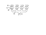
図1は4気筒4サイクルエンジンの気筒配列と吸/排気構造の本発明に係わる要部を示す概略図である。図において、気筒1、2、3、4は、それぞれ気筒1について符号を付した如くシリンダ室10と吸気ポート20と排気ポート30とを備えており,吸気ポート20および排気ポート30は、それぞれ図示は省略されている吸気弁および排気弁により開閉されるようになっている。このうち特に排気ポート30を開閉する排気弁は、従来のクランク軸回転に同期して回転されるカムによりクランク軸回転角や吸気弁の開閉に同期してのみ開閉されるものではなく、電磁式開閉弁の如く、図には示されていないマイクロコンピュータを備えた機関運転制御装置の制御判断に応じて独自に任意の開閉タイミングにて開閉され得るようになっているものである。この種の電磁式開閉弁の例は、例えば本件出願人と同一人の出願による特開2001−193504号公報に示されている。但し、本発明にとって、電磁式開閉弁は排気ポート30の開閉に適用できる一例であり、本発明における排気ポート30の開閉は、上記のとおり機関運転制御装置の制御判断に応じて独自に任意の開閉タイミングにて開閉され得さえすれば、電磁式開閉弁により行なわれることに限られない。4気筒内燃機関の排気ポートは一般に図示の如きは熊手型の排気マニホルド40により相互に接続されている。排気マニホルドの集合部には絞り弁50が設けられていてよい。
【0019】
図示の如く直列に配列された4つの気筒よりなる4気筒4サイクルエンジンにおける各気筒の作動サイクルは180°を単位として相互にずらされており、図示の如く左側より気筒を順に気筒1、2、3、4とすると、その作動順序は1−3−4−2である。
【0020】
図2はこれらの気筒を上から作動順に並べてその作動サイクルを示した線図である。今説明の便宜上、機関始動に当たって気筒1が最初に吸気行程に入るとすると、気筒1が吸気行程を終えて圧縮行程に入るとき気筒3が吸気行程を開始し、次いで気筒1が爆発行程に入るとき気筒4が吸気行程を開始し、気筒1が排気行程に入るとき気筒2が吸気行程を開始する。そこで、本発明により各気筒が吸気行程中にも排気ポートを開くことができるようになっていれば、気筒1の排気行程に重なる気筒2の吸気行程中に気筒2の排気ポートを開くことにより、排気マニホルド40の一部を通るだけで気筒1からの排気を直ちに気筒2の吸気に混入させ、吸気の温度上昇を図ることができる。尚、このとき気筒1からの排気を気筒2の排気ポートが受けやすくするよう、絞り弁50を一時的に閉じる制御が行われてよい。
【0021】
更に本発明によれば、気筒3および4のいずれか一方または両方は、吸気行程が図中破線にて示されていることから示唆されているように、その最初の作動サイクルが実質非作動とされてもよい。かかる気筒3または4の初回作動サイクルの実質非作動は、吸気行程において吸気ポートを開かないこと、あるいは吸気行程と圧縮行程とを通じて吸気ポートを開いたままとすること、のいずれよって行われてもよく、またいずれによる場合にも爆発行程ための燃料は供給しないことによって行われてよい。
【0022】
かくして、気筒3および4の両方の初回作動サイクルが実質非作動とされるときには、機関始動時に吸気加熱が行われないのは最初に吸気行程を行う気筒1のみで済み、機関の冷温始動時にも燃料の燃焼が改善されて排気中へのHCやCOの排出が抑制される。尚、図示の実施例では、気筒2に続く気筒1の吸気行程においては、気筒1の排気行程の終了時に排気ポートを閉じる時期が次の吸気行程に幾分重なるまで延長され、それ自身の先の作動サイクルにて生じた排気の一部が吸気に混入され、吸気の加熱が行なわれる。
【0023】
これ以後、気筒3の2回目の作動サイクルにおいては、その吸気行程の初期に気筒3の排気ポートが適宜開かれることにより、気筒1にて生じた排気の一部が吸気中に混入され、その加熱が行なわれる。同様に、続く気筒4の2回目の作動サイクルにおいては、その吸気行程の初期にその排気ポートが適宜開かれ、気筒1にて生じた排気、またはこのとき気筒2は既に排気行程にあるので、気筒2より得られた排気の一部が吸気中に混入され、その加熱が行なわれる。気筒2もまた、その排気行程の終りに、排気ポートが次の吸気行程に適宜重なるようその閉じ時点が適宜遅らされ、次の吸気行程における吸気が排気の一部の混入により加熱されてよい。同様のことは作動を開始した気筒3および4についても行なわれてよい。
【0024】
4気筒4サイクルエンジンにおいては、図2に示すとおり機関始動時に最初に吸気行程を行う気筒の排気により後続の気筒の吸気加熱が可能となるのは、最初の気筒1から数えて三つ目の気筒であり、その間には気筒1の排気による吸気加熱が行えない二つの気筒があるので、これら二つの気筒の両者について第1回目の作動サイクルを行わせなければ,機関始動時のHCやCOの排出をよりよく抑制することができるが、機関始動の迅速性やその他の条件に応じて初回の作動サイクルを非作動とするのは、気筒3または4のいずれか一方にのみ限られてもよい。また、かかる排気による吸気の加熱は、各気筒について冷温始動後10〜30サイクルを実行する程度までであってよく、それによってシリンダヘッドやシリンダ壁は排気混入による吸気の加熱が行われなくても好ましいからざるHCやCOの排出を生じない程度に暖機される。
【0025】
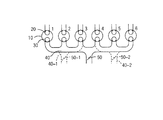
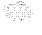
図3は直列6気筒4サイクルエンジンについて、その気筒配列とその吸/排気構造を、排気マニホルドが単一の場合について実線にて、また排気マニホルドを二つに分けた場合について破線にて示す、図1と同様の概略図である。この図においても、直列に配列された6つの気筒は気筒1〜6として番号を付されて示されている。各気筒はシリンダ室10と吸気ポート20と排気ポート30とを備えており、各気筒の排気ポート30は熊手型の単一の排気マニホルド40または二つの排気マニホルド40−1および40−2により互いに接続されている。排気マニホルドにはその集合部に絞り弁50または50−1および50−2が設けられている。かかる直列6気筒4サイクルエンジンにおける各気筒間の作動サイクルは120°を単位として順次ずらされており、通常その作動順序は1−5−3−6−2−4である。
【0026】
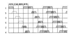
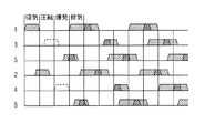
図4は上記の如き作動順序にて6つの気筒が順次サイクル作動を行う場合の各気筒における吸気、圧縮、爆発、排気行程を示す線図である。単一の排気マニホルドの場合には、機関が気筒1の吸気行程から始動されるとすると、気筒2および4は初回の吸気行程時から気筒1の排気を吸気の加熱のために得ることができる。また、かかる実施例においても、気筒5、3、6のいずれか少なくとも一つについて、その第1回目の作動サイクルを実質的に行わせなければ、それだけ機関始動時のHCやCOの排出を抑制することができる。勿論、気筒5、3、6の全てついて第1回目の作動サイクルを行なわせなければ、HCやCOの抑制については最大の効果が得られるが、この場合にも機関始動の迅速性に対する要求やその他の状況に応じて、第1回目の作動サイクルを行わせないのは、これら三つの気筒のうちいずれか一つまたは二つに制限されてよい。またこの実施例においても、各気筒が作動サイクルを開始したときには、次のサイクルにおける吸気の加熱は、それ自身の先のサイクルにおける排気ポートの閉じ時点を吸気行程の途中まで遅らせることにより、それ自身の先の作動サイクルにおける排気の一部によって行われてよい。絞り弁50、50−1、50−2の作動要領は4気筒4サイクルエンジンについて上に説明したのと同じである。
【0027】
排気マニホルドが二つに分けられた場合には、相互に他の気筒からの排気を吸気の加熱に利用できるのは二つの群のそれぞれに属する三つの気筒間のみである。気筒1−2−3の群については、気筒2がその最初の吸気行程に気筒1からの排気を用いることができ、気筒4−5−6の群については、気筒4がその最初の吸気行程に気筒5からの排気を用いることができる。それぞれの群について絞り弁50−1または50−2が同様に開閉制御されてよい。更に、気筒1−2−3の群については、気筒3の初回の作動サイクルが実質非作動とされてよく、気筒4−5−6の群については、気筒6の初回の作動サイクルが実質非作動とされてよい。
【0028】
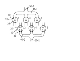
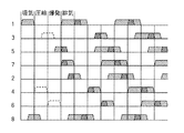
図5は3気筒ずつ二つの群に分けられたV型6気筒4サイクルエンジンの気筒配列および吸/排気構造の例を示す図1および図3と同様の概略図である。図5においても、気筒1〜6の各々はシリンダ室10と吸気ポート20と排気ポート30とを備えており、気筒1と3と5とがそれらの排気ポートを排気マニホルド40−1より互いに接続されて一つの群とされ、気筒2と4と6とがそれらの排気ポートを排気マニホルド40−2より互いに接続されて他の一つの群とされている。排気マニホルド40−1には絞り弁50−1が、また排気マニホルド40−2には絞り弁50−2が設けられている。かかるV型6気筒4サイクルエンジンにおける気筒のサイクル作動の順序は気筒1−2−3−4−5−6であり、各気筒における吸気、圧縮、爆発、排気行程を順に示せば図6の線図に示す通りである。
【0029】
この場合にも、相互に他の気筒からの排気を吸気の加熱に利用できるのは二つの群のそれぞれに属する三つの気筒間のみである。気筒1−3−5の群については、気筒5がその最初の吸気行程に気筒1からの排気を用いることができ、気筒2−4−6の群については、気筒6がその最初の吸気行程に気筒2からの排気を用いることができる。それぞれの群について絞り弁50−1または50−2が同様に開閉制御されてよい。更に、気筒1−3−5の群については、気筒3の初回の作動サイクルが実質非作動とされてよく、気筒2−4−6の群については、気筒4の初回の作動サイクルが実質非作動とされてよい。
【0030】
図7は気筒が4つずつ2つの群に分けられたV型8気筒4サイクルエンジンについての気筒配列と吸/排気構造の例を示す図1、3、5と同様の図である。かかるV型8気筒4サイクルエンジンにおける気筒1〜8の作動順序は、好ましい一例として1−8−4−3−6−5−7−2とされ、各気筒における吸気、圧縮、爆発、排気行程を順に示せば図8の線図に示す通りである。この場合にも、他の気筒の排気により吸気の加熱が可能なのは気筒1と3と5と7の間および気筒2と4と6と8の間である。
【0031】
気筒1−3−5−7の群については、気筒5および7がその最初の吸気行程に気筒1からの排気を用いることができ、気筒2−4−6−8の群については、気筒2がその最初の吸気行程に気筒8からの排気を用いることができる。更に、気筒1−3−5−7の群については、気筒3の初回の作動サイクルが実質非作動とされてよく、気筒4−5−6−8の群については、気筒4および6の初回の作動サイクルが実質非作動とされてよい。それぞれの群について絞り弁50−1または50−2が同様に開閉制御されてよい。
【0032】
以上においては、本発明をいくつかの実施例について詳細に説明したが、本発明がこれらの実施例にのみ限られるもではなく、本発明の範囲内にて他に種々の実施例が可能であることは当業者にとって明らかであろう。
【図面の簡単な説明】
【図1】4気筒4サイクルエンジンの気筒配列と吸/排気構造を本発明に係る要部についてのみ示す概略図。
【図2】図1に示す4気筒4サイクルエンジンが気筒1の吸気行程から始動されるとして各気筒の作動サイクルを示す線図。
【図3】直列6気筒4サイクルエンジンの気筒配列と吸/排気構造を本発明に係る要部についてのみ示す概略図。
【図4】図3に示す直列6気筒4サイクルエンジンが気筒1の吸気行程から始動されるとして各気筒の作動サイクルを示す線図。
【図5】V型6気筒4サイクルエンジンの気筒配列と吸/排気構造を本発明に係る要部についてのみ示す概略図。
【図6】図5に示すV型6気筒4サイクルエンジンが気筒1の吸気行程から始動されるとして各気筒の作動サイクルを示す線図。
【図7】V型8気筒4サイクルエンジンの気筒配列と吸/排気構造を本発明に係る要部についてのみ示す概略図。
【図8】図7に示すV型8気筒4サイクルエンジンが気筒1の吸気行程から始動されるとして各気筒の作動サイクルを示す線図。
【符号の説明】
10…シリンダ室
20…吸気弁
30…排気弁
40、40−1、40−2…排気マニホルド
50、50−1、50−2…絞り弁[0001]
BACKGROUND OF THE INVENTION
The present invention relates to an internal combustion engine operation method, and more particularly, to an operation method involving exhaust gas recirculation (EGR) of a multi-cylinder internal combustion engine.
[0002]
[Prior art]
In an internal combustion engine, a part of the exhaust system is connected to a part of the intake system by the gas passage means, and a part of the exhaust gas is returned to the intake side by the gas passage means and mixed into the intake air. Known as technology. Such exhaust gas recirculation has an effect of suppressing the discharge of NOx into the exhaust gas. In many cases, NOx emissions in an internal combustion engine are a problem in operation after the engine is sufficiently warmed up, and HC and CO emissions are more problematic in the operation until the engine is warmed up. It is.
[0003]
In a diesel engine equipped with an oxidation catalyst in the exhaust system, we coped with the fact that the oxidation catalyst became inoperable due to a decrease in exhaust gas temperature due to a decrease in the output of each cylinder during idle operation, and exited the exhaust ports of half of the cylinders during idle operation. Exhaust gas recirculation is performed by returning the exhaust gas to the intake ports of the remaining half of the cylinders, and the exhaust gas that reaches the oxidation catalyst becomes exhaust gas that has passed through the cylinder twice, so that the temperature is raised and the oxidation catalyst is activated. Is described in JP-A-9-112256.
[0004]
[Problems to be solved by the invention]
When the internal combustion engine is started, particularly at a cold start, the cylinder is cold, so that incomplete combustion of the fuel cannot be avoided, and there is a problem that the concentration of HC and CO in the exhaust becomes high. For this, it is conceivable to heat the intake air by exhaust gas recirculation, but a conventional exhaust gas recirculation structure in which a part of the exhaust system is connected to a part of the intake system by a gas passage means such as a pipe. In this case, since the exhaust gas recirculation passage is considerably long and its heat capacity is considerably large, it takes a considerable time delay to obtain the heating of the intake air by exhaust gas recirculation at the cold start of the engine.
[0005]
The present invention relates to the problem of exhaust purification when starting an engine, particularly at a cold start, and the opening / closing timing can be controlled independently of the rotation of the crankshaft, like an electromagnetic intake / exhaust valve that has been put into practical use in recent years. By using the intake / exhaust valve, especially the exhaust valve, exhaust gas is recirculated between the cylinders through the exhaust port to heat the intake air at an early stage, thereby achieving exhaust purification when starting the engine, particularly when starting cold. This is the main issue.
[0006]
[Means for Solving the Problems]
In order to solve such a problem, the present invention relates to a multi-cylinder internal combustion engine having first and second cylinders whose exhaust ports are connected to each other by an exhaust manifold. Provided is an inter-cylinder EGR operation method for a multi-cylinder internal combustion engine, wherein the operation is performed so as to be introduced into the second cylinder through an exhaust manifold through an exhaust port of the second cylinder in an intake stroke. Is.
[0007]
The predetermined period may naturally include the start of the internal combustion engine in view of the main problems of the invention described above. However, the exhaust gas recirculation from the exhaust manifold through the exhaust port is a gas like a pipe from the exhaust system. Compared to the conventional exhaust gas recirculation that returns the exhaust gas to the intake system via the passage means, no recirculation gas passage means is required and the controllability including the on / off speed is excellent. Therefore, it may be appropriately performed according to arbitrary engine operation control even during engine operation other than when the engine is started.
[0008]
In such inter-cylinder EGR operation, the intake stroke of the second cylinder may overlap with at least a part of the exhaust stroke of the first cylinder.
[0009]
In addition to the first and second cylinders, the third cylinder in which the exhaust ports are connected to each other in the exhaust manifold is located between the first and second cylinders in the order of the operation cycle. When the first cylinder is a cylinder that first performs an intake stroke when starting the engine, the third cylinder may not be supplied with fuel in the first operation cycle when starting the engine.
[0010]
In addition, a throttle valve is provided at a collecting portion of the exhaust manifold, and when the exhaust of the first cylinder is introduced into the second cylinder from the exhaust port of the second cylinder through the exhaust manifold. The throttle valve may be throttled.
[0011]
Operation and effect of the invention
If an appropriate amount of exhaust can be mixed with the intake air at the start of the internal combustion engine, especially at a cold start, the temperature of the intake air compressed in the cylinder chamber is raised by the heat of the exhaust, and fuel combustion in the subsequent explosion stroke is improved. The amount of HC and CO discharged in the exhaust can be reduced. However, since the exhaust gas is generated only after the intake, compression, and explosion strokes, it is impossible to mix the exhaust gas into the intake air in the intake stroke that is first performed when the engine is started. However, in a multi-cylinder internal combustion engine, each cylinder is shifted sequentially to perform the intake, compression, explosion, and exhaust strokes. If the exhaust from the cylinder performing the operation cycle is supplied from the exhaust port via the exhaust manifold, the exhaust from the preceding operation cycle may be received earlier than the exhaust is supplied through the conventional exhaust gas recirculation path. It is possible to obtain the intake air heating effect at an early stage.
[0012]
Further, as already described, the exhaust gas recirculation from the exhaust manifold through the exhaust port is not compared with the conventional exhaust gas recirculation that returns the exhaust gas to the intake system through the gas passage means such as a pipe from the exhaust system. In addition to the structural advantage of not requiring recirculation gas passage means, it also has excellent controllability including rapid on / off, so only for the suppression of HC and CO during engine start-up In addition, the exhaust gas recirculation rate can be controlled to a higher degree throughout the exhaust gas recirculation operation including the suppression of NOx.
[0013]
By the exhaust gas recirculation from the exhaust port as described above, the intake air heating of the second cylinder can be achieved earliest by the exhaust of the first cylinder because the intake stroke of the second cylinder is the exhaust stroke of the first cylinder. This is when it overlaps at least part of it.
[0014]
In addition to the first and second cylinders, the cylinder in which the exhaust ports are connected to each other in the exhaust manifold includes a third cylinder located between the first and second cylinders in the order of the operation cycle. In addition, when the first cylinder is a cylinder that performs an intake stroke first at the time of engine start, if the third cylinder is not supplied with fuel in the first operation cycle at the time of engine start, Reduce the number of operating cycles that do not require heating, and more effectively demonstrate the effect of intake air heating by exhaust gas recirculation from the exhaust port, and more effectively suppress the generation of HC and CO during engine startup, especially during cold start Can do.
[0015]
Current multi-cylinder internal combustion engines, particularly multi-cylinder internal combustion engines for vehicles, usually have four or more cylinders. Such a multi-cylinder internal combustion engine is designed to increase its rotational speed for a moment after starting even when it is started in a cold state. In such a multi-cylinder internal combustion engine, even if the first operation cycle of about 1, 2 or 3 cylinders following the cylinder that first operates at the time of engine start is deactivated, there is no problem in engine startability, rather the engine There is no advantage that the engine speed increases immediately after starting, and the engine starting is quieted.
[0016]
Furthermore, a throttle valve is provided at a collection portion of the exhaust manifold, and the throttle valve is appropriately throttled when the exhaust of the first cylinder is introduced into the second cylinder from the exhaust port of the second cylinder via the exhaust manifold. By doing so, the exhaust discharged from the exhaust port of the first cylinder can be appropriately directed to the exhaust port of the second cylinder in the exhaust manifold, and the inter-cylinder EGR via the exhaust manifold and the exhaust port can be reduced. This can be done more appropriately.
[0017]
DETAILED DESCRIPTION OF THE INVENTION
Hereinafter, embodiments of the present invention will be described in detail with reference to the accompanying drawings.
[0018]
FIG. 1 is a schematic view showing a main part according to the present invention of a cylinder arrangement and intake / exhaust structure of a four-cylinder four-cycle engine. In the figure,
[0019]
In the four-cylinder four-cycle engine composed of four cylinders arranged in series as shown in the figure, the operating cycles of the cylinders are shifted from each other in units of 180 °. Assuming 3 and 4, the operation sequence is 1-3-4-2.
[0020]
FIG. 2 is a diagram showing the operation cycle of these cylinders arranged in order of operation from the top. For convenience of explanation, if the
[0021]
In addition, according to the present invention, one or both of
[0022]
Thus, when the initial operation cycle of both the
[0023]
Thereafter, in the second operation cycle of the
[0024]
In the four-cylinder four-cycle engine, as shown in FIG. 2, the third cylinder, counting from the
[0025]
FIG. 3 shows the cylinder arrangement and the intake / exhaust structure of an in-line 6-cylinder four-cycle engine with a solid line when the exhaust manifold is single, and a broken line when the exhaust manifold is divided into two. It is the schematic similar to FIG. Also in this figure, the six cylinders arranged in series are numbered and shown as cylinders 1-6. Each cylinder includes a
[0026]
FIG. 4 is a diagram showing intake, compression, explosion, and exhaust strokes in each cylinder when six cylinders sequentially cycle in the operation sequence as described above. In the case of a single exhaust manifold, if the engine is started from the intake stroke of
[0027]
When the exhaust manifold is divided into two, the exhaust from the other cylinders can be used for heating the intake air only between the three cylinders belonging to each of the two groups. For the group of cylinders 1-2-3,
[0028]
FIG. 5 is a schematic view similar to FIGS. 1 and 3 showing an example of the cylinder arrangement and intake / exhaust structure of a V-type 6-cylinder four-cycle engine divided into two groups of three cylinders. Also in FIG. 5, each of the
[0029]
In this case as well, exhaust gas from other cylinders can be used for heating the intake air only between the three cylinders belonging to each of the two groups. For the group of cylinders 1-3-5, the
[0030]
FIG. 7 is a view similar to FIGS. 1, 3 and 5 showing an example of the cylinder arrangement and intake / exhaust structure for a V-type 8-cylinder 4-cycle engine in which four cylinders are divided into two groups. The operation order of the
[0031]
For the group of cylinders 1-3-5-7,
[0032]
Although the present invention has been described in detail with reference to several embodiments, the present invention is not limited to these embodiments, and various other embodiments are possible within the scope of the present invention. It will be apparent to those skilled in the art.
[Brief description of the drawings]
BRIEF DESCRIPTION OF DRAWINGS FIG. 1 is a schematic view showing a cylinder arrangement and an intake / exhaust structure of a four-cylinder four-cycle engine only with respect to main parts according to the present invention.
2 is a diagram showing an operation cycle of each cylinder on the assumption that the four-cylinder four-cycle engine shown in FIG. 1 is started from the intake stroke of the
FIG. 3 is a schematic diagram showing only a main part according to the present invention of a cylinder arrangement and an intake / exhaust structure of an in-line six-cylinder four-cycle engine.
4 is a diagram showing an operation cycle of each cylinder on the assumption that the in-line six-cylinder four-cycle engine shown in FIG. 3 is started from the intake stroke of the
FIG. 5 is a schematic view showing only a main part according to the present invention of a cylinder arrangement and an intake / exhaust structure of a V-type six-cylinder four-cycle engine.
6 is a diagram showing an operation cycle of each cylinder on the assumption that the V-type six-cylinder four-cycle engine shown in FIG. 5 is started from the intake stroke of the
FIG. 7 is a schematic view showing only a main part according to the present invention of a cylinder arrangement and an intake / exhaust structure of a V-type 8-cylinder 4-cycle engine.
8 is a diagram showing an operation cycle of each cylinder on the assumption that the V-type eight-cylinder four-cycle engine shown in FIG. 7 is started from the intake stroke of the
[Explanation of symbols]
DESCRIPTION OF
Claims (3)
Priority Applications (1)
| Application Number | Priority Date | Filing Date | Title |
|---|---|---|---|
| JP2001267353A JP4635397B2 (en) | 2001-09-04 | 2001-09-04 | Inter-cylinder EGR operation method of multi-cylinder internal combustion engine |
Applications Claiming Priority (1)
| Application Number | Priority Date | Filing Date | Title |
|---|---|---|---|
| JP2001267353A JP4635397B2 (en) | 2001-09-04 | 2001-09-04 | Inter-cylinder EGR operation method of multi-cylinder internal combustion engine |
Publications (2)
| Publication Number | Publication Date |
|---|---|
| JP2003074416A JP2003074416A (en) | 2003-03-12 |
| JP4635397B2 true JP4635397B2 (en) | 2011-02-23 |
Family
ID=19093490
Family Applications (1)
| Application Number | Title | Priority Date | Filing Date |
|---|---|---|---|
| JP2001267353A Expired - Fee Related JP4635397B2 (en) | 2001-09-04 | 2001-09-04 | Inter-cylinder EGR operation method of multi-cylinder internal combustion engine |
Country Status (1)
| Country | Link |
|---|---|
| JP (1) | JP4635397B2 (en) |
Families Citing this family (1)
| Publication number | Priority date | Publication date | Assignee | Title |
|---|---|---|---|---|
| EP1811154B1 (en) * | 2004-10-20 | 2013-12-11 | Koichi Hatamura | Engine control method |
Family Cites Families (4)
| Publication number | Priority date | Publication date | Assignee | Title |
|---|---|---|---|---|
| JPS609419Y2 (en) * | 1979-10-03 | 1985-04-03 | 株式会社兼坂技術研究所 | Internal combustion engine starting accelerator |
| JPS56162238A (en) * | 1980-05-19 | 1981-12-14 | Nissan Motor Co Ltd | Promotion of starting of diesel engine |
| JPH01136666U (en) * | 1988-03-15 | 1989-09-19 | ||
| JPH0586992A (en) * | 1991-09-30 | 1993-04-06 | Mazda Motor Corp | Egr control device for inter-cylinder fuel-injection type engine |
-
2001
- 2001-09-04 JP JP2001267353A patent/JP4635397B2/en not_active Expired - Fee Related
Also Published As
| Publication number | Publication date |
|---|---|
| JP2003074416A (en) | 2003-03-12 |
Similar Documents
| Publication | Publication Date | Title |
|---|---|---|
| US7308872B2 (en) | Method and apparatus for optimized combustion in an internal combustion engine utilizing homogeneous charge compression ignition and variable valve actuation | |
| JP3963144B2 (en) | Control device for spark ignition engine | |
| JP4954708B2 (en) | engine | |
| JP2004132191A (en) | Control device for spark ignition engine | |
| CN107575276B (en) | Engine system and method and system for engine | |
| JP3280758B2 (en) | Intake device for engine with mechanical supercharger | |
| JP4253984B2 (en) | Diesel engine control device | |
| JP2009243360A (en) | Engine combustion control device | |
| JP4635397B2 (en) | Inter-cylinder EGR operation method of multi-cylinder internal combustion engine | |
| JP2004190514A (en) | Internal combustion engine with variable valve timing mechanism | |
| JPH08218879A (en) | Intake structure of 4-cycle engine | |
| JP2006336579A (en) | Control device for internal combustion engine | |
| JP4102268B2 (en) | Compression ignition internal combustion engine | |
| JP2005291044A (en) | Multi-cylinder engine with turbocharger | |
| JP5549544B2 (en) | Control device for internal combustion engine | |
| JP2004124752A (en) | Control device for supercharged spark ignition engine | |
| JP3711941B2 (en) | Control device for spark ignition engine | |
| JP4045867B2 (en) | Operation mode detection device and control device for spark ignition engine | |
| JP4285091B2 (en) | Control device for spark ignition engine | |
| JP3826850B2 (en) | Control device for spark ignition engine | |
| JP3888261B2 (en) | Control device for spark ignition engine | |
| JP3972744B2 (en) | Control device for spark ignition type 4-cycle engine | |
| JP4779386B2 (en) | diesel engine | |
| JP4107180B2 (en) | Control device for spark ignition engine | |
| JPH10274072A (en) | In-cylinder injection engine with turbocharger |
Legal Events
| Date | Code | Title | Description |
|---|---|---|---|
| A621 | Written request for application examination |
Free format text: JAPANESE INTERMEDIATE CODE: A621 Effective date: 20080820 |
|
| A977 | Report on retrieval |
Free format text: JAPANESE INTERMEDIATE CODE: A971007 Effective date: 20100729 |
|
| A131 | Notification of reasons for refusal |
Free format text: JAPANESE INTERMEDIATE CODE: A131 Effective date: 20100803 |
|
| A521 | Request for written amendment filed |
Free format text: JAPANESE INTERMEDIATE CODE: A523 Effective date: 20101001 |
|
| TRDD | Decision of grant or rejection written | ||
| A01 | Written decision to grant a patent or to grant a registration (utility model) |
Free format text: JAPANESE INTERMEDIATE CODE: A01 Effective date: 20101026 |
|
| A01 | Written decision to grant a patent or to grant a registration (utility model) |
Free format text: JAPANESE INTERMEDIATE CODE: A01 |
|
| A61 | First payment of annual fees (during grant procedure) |
Free format text: JAPANESE INTERMEDIATE CODE: A61 Effective date: 20101108 |
|
| FPAY | Renewal fee payment (event date is renewal date of database) |
Free format text: PAYMENT UNTIL: 20131203 Year of fee payment: 3 |
|
| FPAY | Renewal fee payment (event date is renewal date of database) |
Free format text: PAYMENT UNTIL: 20131203 Year of fee payment: 3 |
|
| LAPS | Cancellation because of no payment of annual fees |