JP4635374B2 - Printing to the end of the print media without soiling the platen - Google Patents
Printing to the end of the print media without soiling the platen Download PDFInfo
- Publication number
- JP4635374B2 JP4635374B2 JP2001144538A JP2001144538A JP4635374B2 JP 4635374 B2 JP4635374 B2 JP 4635374B2 JP 2001144538 A JP2001144538 A JP 2001144538A JP 2001144538 A JP2001144538 A JP 2001144538A JP 4635374 B2 JP4635374 B2 JP 4635374B2
- Authority
- JP
- Japan
- Prior art keywords
- dot
- sub
- element group
- print medium
- partial
- Prior art date
- Legal status (The legal status is an assumption and is not a legal conclusion. Google has not performed a legal analysis and makes no representation as to the accuracy of the status listed.)
- Expired - Fee Related
Links
Images


Landscapes
- Ink Jet (AREA)
- Handling Of Sheets (AREA)
Description
【0001】
【発明の属する技術分野】
この発明は、ドット記録ヘッドを用いて記録媒体の表面にドットの記録を行う技術に関し、特に、プラテンを汚すことなく印刷用紙の端部まで印刷を行う技術に関する。
【0002】
【従来の技術】
近年、コンピュータの出力装置として、印刷ヘッドのノズルからインクを吐出するプリンタが広く普及している。図27は、従来のプリンタの印刷ヘッドの周辺を示す側面図である。印刷用紙Pは、プラテン26o上でヘッド28oに向かい合うように支持される。そして、印刷用紙Pは、プラテン26oの上流に配された上流側紙送りローラ25p,25q、およびプラテン26の下流に配された下流側紙送りローラ25r,25sによって、矢印Aの方向に送られる。ヘッドからインクが吐出されると、印刷用紙P上に順次、ドットが記録されて、画像が印刷される。
【0003】
【発明が解決しようとする課題】
上記のようなプリンタにおいて印刷用紙の端まで画像を印刷しようとすると、印刷用紙の端が印刷ヘッド下方、すなわちプラテン上に位置するように印刷用紙を配し、印刷ヘッドからインク滴を吐出させる必要がある。しかし、そのような印刷においては、印刷用紙の送りの誤差やインク滴の着弾位置のずれなどによって、インク滴が本来着弾すべき印刷用紙端部からはずれてプラテン上に着弾してしまう場合がある。そのような場合には、プラテン上に着弾したインクによって、その後にプラテン上を通過する印刷用紙が、汚されてしまう。
【0004】
この発明は、従来技術における上述の課題を解決するためになされたものであり、プラテンにインク滴を着弾させることなく印刷用紙の端部まで印刷を行う技術を提供することを目的とする。
【0005】
【課題を解決するための手段およびその作用・効果】
上述の課題の少なくとも一部を解決するため、本発明では、インク滴を吐出する複数のドット形成要素からなるドット形成要素群が設けられたドット記録ヘッドを用いて印刷媒体の表面にドットの記録を行うドット記録装置を対象として、所定の処理を行う。このドット記録装置は、ドット記録ヘッドと印刷媒体の少なくとも一方を駆動して主走査を行う主走査駆動部と、主走査の最中に複数のドット形成要素のうちの少なくとも一部を駆動してドットの形成を行わせるヘッド駆動部と、主走査の行路の少なくとも一部において複数のドット形成要素と向かい合うように、主走査の方向に延長して設けられ、印刷媒体をドット記録ヘッドと向かい合うように支持するプラテンと、主走査の合間に印刷媒体を主走査の方向と交わる方向に駆動して副走査を行う副走査駆動部と、各部を制御するための制御部と、を備えている。
【0006】
このドット記録装置のプラテンは、複数のドット形成要素の一部のドット形成要素からなる第1の部分ドット形成要素群と向かい合う位置に主走査の方向に延長して設けられ、印刷媒体を支える第1の支持部と、複数のドット形成要素のうち第1の部分ドット形成要素群よりも副走査の方向の下流側に設けられる第2の部分ドット形成要素群と向かい合う位置に、主走査の方向に延長して設けられる第1の溝部と、複数のドット形成要素のうち第2の部分ドット形成要素群よりも副走査の方向の下流側に設けられる第3の部分ドット形成要素群と向かい合う位置に主走査の方向に延長して設けられ、印刷媒体を支える第2の支持部と、複数のドット形成要素のうち第3の部分ドット形成要素群よりも副走査の方向の下流側に設けられる第4の部分ドット形成要素群と向かい合う位置に、主走査の方向に延長して設けられる第2の溝部と、を有している。
【0007】
そのようなドット記録装置において、以下のような印刷を行う。ここで、印刷媒体の表面部を、上から順に、上端を含む上端部、上端移行部、中間部、下端移行部、下端を含む下端部、と区分する。その印刷とは、まず、第1ないし第3の部分ドット形成要素群を使用せずに、第4の部分ドット形成要素群を使用して、第1の副走査モードで、上端部にドットを形成する。そして、第1ないし第4の部分ドット形成要素群を使用して、第1の副走査モードで、上端移行部にドットを形成する。その後、第1ないし第4の部分ドット形成要素群を使用して、副走査の最大の送り量が第1の副走査モードの副走査の最大の送り量よりも大きい第2の副走査モードで、中間部にドットを形成する。
【0008】
このような態様とすれば、上端部において、プラテンを汚すことなく印刷媒体の端までドットを形成することができる。そして、第4の部分ドット形成要素群を使用する上端部のドット形成から、第1ないし第4の部分ドット形成要素群を使用する中間部のドット形成に、副走査の逆送りを行うことなくスムーズに移行することができる。
【0009】
なお、上端部のドット形成の際には、印刷媒体がプラテンに支持され、かつ、印刷媒体の上端が第2の溝部の開口上にあるときに、ドットを形成するようにすることができる。このような態様とすれば、第4の部分ドット形成要素群を使用して、印刷媒体の上端に余白なくドットを形成することができる。
【0010】
また、中間部におけるドット形成の後、さらに、以下のような印刷を行うことが好ましい。すなわち、第1の部分ドット形成要素群を使用せずに、第2ないし第4の部分ドット形成要素群を使用して、副走査の最大の送り量が第2の副走査モードの副走査の最大の送り量よりも小さい第3の副走査モードで、下端移行部にドットを形成する。そして、第1、第3および第4の部分ドット形成要素群を使用せずに、第2の部分ドット形成要素群を使用して、第3の副走査モードで、下端部にドットを形成する。
【0011】
このような態様とすれば、下端部において、プラテンを汚すことなく印刷媒体の端までドットを形成することができる。そして、第1ないし第4の部分ドット形成要素群を使用する中間部のドット形成から、第2の部分ドット形成要素群を使用する下端部のドット形成に、副走査の逆送りを行うことなくスムーズに移行することができる。
【0012】
なお、第2の部分ドット形成要素群のノズルは、第1の部分ドット形成要素群のノズルよりも、印刷媒体上のドット形成位置の平均ズレ量が小さいことが好ましい。このような態様とすれば、第2の部分ドット形成要素群のノズルのみを使用する下端部の印刷において、高品質な印刷を行うことができる。
【0013】
なお、下端部のドット形成の際には、印刷媒体がプラテンに支持され、かつ、印刷媒体の下端が第1の溝部の開口上にあるときに、ドットを形成するようにすることができる。このような態様とすれば、第2の部分ドット形成要素群を使用して、印刷媒体の下端に余白なくドットを形成することができる。
【0014】
なお、プラテンが、さらに、複数のドット形成要素のうち第4の部分ドット形成要素群よりも副走査の方向の下流側に設けられる第5の部分ドット形成要素群と向かい合う位置に主走査の方向に延長して設けられ、印刷媒体を支える第3の支持部と、を有している場合には、以下のような印刷を行うことが好ましい。
【0015】
まず、第1、第2、第3および第5の部分ドット形成要素群を使用せずに、第4の部分ドット形成要素群を使用して、第1の副走査モードで、上端部にドットを形成する。そして、第1ないし第4の部分ドット形成要素群を使用して、第1の副走査モードで、上端移行部にドットを形成する。その後、第1ないし第5の部分ドット形成要素群を使用して、副走査の最大の送り量が第1の副走査モードの副走査の最大の送り量よりも大きい第2の副走査モードで、中間部にドットを形成する。
【0016】
このような態様とすれば、上端部において、プラテンを汚すことなく印刷媒体の端までドットを形成することができる。そして、第4の部分ドット形成要素群を使用する上端部のドット形成から、第1ないし第5の部分ドット形成要素群を使用する中間部のドット形成に、副走査の逆送りを行うことなくスムーズに移行することができる。
【0017】
なお、第4の部分ドット形成要素群のノズルは、第5の部分ドット形成要素群のノズルよりも、印刷媒体上のドット形成位置の平均ズレ量が小さいことが好ましい。このような態様とすれば、第4の部分ドット形成要素群のノズルのみを使用する下端部の印刷において、高品質な印刷を行うことができる。
【0018】
また、中間部におけるドット形成の後、さらに、以下のような印刷を行うことが好ましい。すなわち、第1の部分ドット形成要素群を使用せずに、第2ないし第5の部分ドット形成要素群を使用して、副走査の最大の送り量が第2の副走査モードの副走査の最大の送り量よりも小さい第3の副走査モードで、下端移行部にドットを形成する。そして、第1、第3、第4および第5の部分ドット形成要素群を使用せずに、第2の部分ドット形成要素群を使用して、第3の副走査モードで、下端部にドットを形成する。
【0019】
このような態様とすれば、下端部において、プラテンを汚すことなく印刷媒体の端までドットを形成することができる。そして、第1ないし第5の部分ドット形成要素群を使用する中間部のドット形成から、第2の部分ドット形成要素群を使用する下端部のドット形成に、副走査の逆送りを行うことなくスムーズに移行することができる。
【0020】
なお、本発明は、以下に示すような種々の態様で実現することが可能である。
(1)ドット記録装置、ドット記録制御装置、印刷装置。
(2)ドット記録方法、ドット記録制御方法、印刷方法。
(3)上記の装置や方法を実現するためのコンピュータプログラム。
(4)上記の装置や方法を実現するためのコンピュータプログラムを記録した記録媒体。
(5)上記の装置や方法を実現するためのコンピュータプログラムを含み搬送波内に具現化されたデータ信号。
【0021】
【発明の実施の形態】
以下で、本発明の実施の形態を実施例に基づいて以下の順序で説明する。
A.実施形態の概要:
B.第1実施例:
B1.装置の全体構成:
B2.画像データと印刷用紙との関係:
B3.印刷中の副走査送り:
C.第2実施例:
D.第3実施例:
E.変形例:
E1.変形例1:
E2.変形例2:
E3.変形例3:
【0022】
A.実施形態の概要:
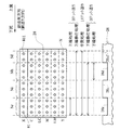
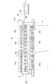
図1は、本発明の実施の形態におけるインクジェットプリンタの印刷ヘッド28上の使用ノズルの変化を示す説明図である。図1においては、左側に印刷ヘッド28の下面を示し、右側に、印刷ヘッド28上の各ノズルに対応するプラテン26の構成を側面図として示している。このプリンタのプラテン26には、副走査方向の上流から順に、上流側支持部26sf、上流側溝部26f、中央支持部26c、下流側溝部26rが設けられている。そして、そのプラテン26と向かい合う印刷ヘッド28上に設けられたノズルは、上流から順に、上流側支持部26sfと向かい合う第1のノズル群Nf、上流側溝部26fと向かい合う第2のノズル群Nh、中央支持部26cと向かい合う第3のノズル群Ni、下流側溝部26rと向かい合う第4のノズル群Nrに分類される。
【0023】
このプリンタは、印刷用紙の上端部については、上端が下流側溝部26r上にあるときに、下流側溝部26rと向かい合う第4のノズル群Nrのみで印刷を行う(上端処理)。そして、印刷用紙の下端部については、下端が上流側溝部26f上にあるときに、上流側溝部26fと向かい合う第2のノズル群Nhのみで印刷を行う(下端処理)。こうすることにより、プラテン26の上面を汚すことなく、印刷用紙の端まで余白なく画像を印刷することができる。また、印刷用紙の中間部は、全ノズル群を使用して印刷を行う(中間処理)。このため、中間部分については高速に印刷を行うことができる。
【0024】
さらに、上端処理と中間処理の間に、上端処理と同じ副走査送りを行い、中間処理と同じく全ノズル群を使用して印刷を行う上端移行処理を行う。また、中間処理と下端処理の間には、下端処理と同じ副走査送りを行い、ノズル群Nh,Ni,Nrを使用して印刷を行う下端移行処理を行う。すなわち、下端移行処理においては、ノズル群Nfは使用しない。これらの移行処理を行うことで、副走査の逆送り、または大きな送りとなる位置合わせ送りを行うことなく、上端処理、中間処理、下端処理をスムーズに行うことができる。その結果、印刷の品質が高くなる。
【0025】
B.第1実施例:
B1.装置の構成:
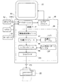
図2は、本印刷装置のソフトウェアの構成を示すブロック図である。コンピュータ90では、所定のオペレーティングシステムの下で、アプリケーションプログラム95が動作している。オペレーティングシステムには、ビデオドライバ91やプリンタドライバ96が組み込まれており、アプリケーションプログラム95からは、これらのドライバを介して、プリンタ22に転送するための画像データDが出力されることになる。画像のレタッチなどを行うアプリケーションプログラム95は、スキャナ12から画像を読み込み、これに対して所定の処理を行いつつビデオドライバ91を介してCRT21に画像を表示している。スキャナ12から供給されるデータORGは、カラー原稿から読み取られ、レッド(R)、グリーン(G)、ブルー(B)の3色の色成分からなる原カラー画像データORGである。
【0026】
このアプリケーションプログラム95が、マウス13やキーボードから入力される指示に応じて印刷命令を発すると、コンピュータ90のプリンタドライバ96が、画像データをアプリケーションプログラム95から受け取り、これをプリンタ22が処理可能な信号(ここではシアン、マゼンタ、ライトシアン、ライトマゼンタ、イエロ、ブラックの各色についての多値化された信号)に変換している。図2に示した例では、プリンタドライバ96の内部には、解像度変換モジュール97と、色補正モジュール98と、ハーフトーンモジュール99と、ラスタライザ100とが備えられている。また、色補正テーブルLUT、ドット形成パターンテーブルDTも記憶されている。
【0027】
解像度変換モジュール97は、アプリケーションプログラム95が扱っているカラー画像データの解像度、即ち、単位長さ当りの画素数をプリンタドライバ96が扱うことができる解像度に変換する役割を果たす。こうして解像度変換された画像データは、まだRGBの3色からなる画像情報であるから、色補正モジュール98は色補正テーブルLUTを参照しつつ、各画素ごとにプリンタ22が使用するシアン(C)、マゼンタ(M)、ライトシアン(LC)、ライトマゼンタ(LM)、イエロ(Y)、ブラック(K)の各色のデータに変換する。
【0028】
色補正されたデータは、例えば256階調等の幅で階調値を有している。ハーフトーンモジュール99は、ドットを分散して形成することによりプリンタ22で、この階調値を表現するためのハーフトーン処理を実行する。ハーフトーンモジュール99は、ドット形成パターンテーブルDTを参照することにより、画像データの階調値に応じて、それぞれのインクドットのドット形成パターンを設定した上で、ハーフトーン処理を実行する。こうして処理された画像データは、ラスタライザ100によりプリンタ22に転送すべきデータ順に並べ替えられ、最終的な印刷データPDとして出力される。印刷データPDは、各主走査時のドットの記録状態を表すラスタデータと副走査送り量を示すデータとを含んでいる。
本実施例では、プリンタ22は印刷データPDに従ってインクドットを形成する役割を果たすのみであり画像処理は行っていないが、勿論これらの処理をプリンタ22で行うものとしても差し支えない。
【0029】
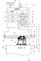
次に、図3によりプリンタ22の概略構成を説明する。図示するように、このプリンタ22は、紙送りモータ23によって用紙Pを搬送する機構と、キャリッジモータ24によってキャリッジ31を摺動軸34の軸方向に往復動させる機構と、キャリッジ31に搭載された印刷ヘッド28を駆動してインクの吐出およびインクドットの形成を行う機構と、これらの紙送りモータ23、キャリッジモータ24、印刷ヘッド28および操作パネル32との信号のやり取りを司る制御回路40とから構成されている。
【0030】
キャリッジ31をプラテン26の軸方向に往復動させる機構は、印刷用紙Pの搬送方向と垂直な方向に架設され、キャリッジ31を摺動可能に保持する摺動軸34とキャリッジモータ24との間に無端の駆動ベルト36を張設するプーリ38と、キャリッジ31の原点位置を検出する位置検出センサ39等から構成されている。
【0031】
キャリッジ31には、黒インク(K)用のカートリッジ71とシアン(C),ライトシアン(LC)、マゼンタ(M),ライトマゼンダ(LM)、イエロ(Y)の6色のインクを収納したカラーインク用カートリッジ72が搭載可能である。キャリッジ31の下部の印刷ヘッド28には計6個のインク吐出用ヘッド61ないし66が形成されており、キャリッジ31に黒(K)インク用のカートリッジ71およびカラーインク用カートリッジ72を上方から装着すると、各インクカートリッジから吐出用ヘッド61ないし66へのインクの供給が可能となる。
【0032】
図4は、印刷ヘッド28におけるインクジェットノズルの配列を示す説明図である。これらのノズルの配置は、ブラック(K)、シアン(C)、ライトシアン(LC)、マゼンタ(M)、ライトマゼンダ(LM)、イエロ(Y)各色ごとにインクを吐出する6組のノズルアレイから成っており、それぞれ48個のノズルが一定のノズルピッチkで一列に配列されている。これらの6組のノズルアレイは主走査方向に沿って並ぶように配列されている。より詳しく言えば、各ノズルアレイの対応するノズル同士は、同一の主走査ライン上に並ぶように配されている。これらのノズルアレイ(ノズル列)が特許請求の範囲にいう「ドット形成要素群」に相当する。なお、「ノズルピッチ」とは、印刷ヘッド上に配されるノズルの副走査方向の間隔が何ラスタ分(すなわち、何画素分)であるかを示す値である。例えば、間に3ラスタ分の間隔をあけて配されているノズルのピッチkは4である。「ラスタ」とは、主走査方向に並ぶ画素の列である。そして、「画素」とは、インク滴を着弾させドットを記録する位置を規定するために、印刷媒体上に(場合によっては印刷媒体の端を超えて)仮想的に定められた方眼状の升目である。なお、図4は、各ノズルの配置を大まかに示したものであり、実施例のヘッドの寸法やノズルの正確な個数を反映したものではない。
【0033】
各ノズルアレイ内のノズルは、副走査方向の上流から順に4個のサブグループに分類される。このサブグループが特許請求の範囲にいう「部分ドット形成要素群」である。以下、各ノズルアレイのサブグループを、副走査方向の上流から順にまとめて、ノズル群Nf,Nh,Ni,Nrと呼ぶ。最も上流側にある第1のノズル群Nfが特許請求の範囲にいう「第1の部分ドット形成要素群」に相当し、第2のノズル群Nhが特許請求の範囲にいう「第2の部分ドット形成要素群」に相当する。第3のノズル群Niが特許請求の範囲にいう「第3の部分ドット形成要素群」に相当し、第4のノズル群Nrが特許請求の範囲にいう「第4の部分ドット形成要素群」に相当する。なお、ここでは、各ノズルアレイの部分ドット形成要素群をまとめて取り扱って、それぞれノズル群Nf,Nh,Ni,Nrとしている。これらのノズル群は、主走査において印刷ヘッド28と向かい合う位置に設けられているプラテン26の、溝部や支持部などの構成部分と対応するように定められている。プラテン26の、溝部や支持部などの構成部分と各ノズル群の対応については後述する。
【0034】
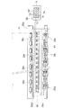
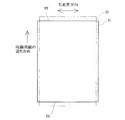
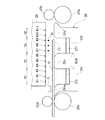
図5は、プラテン26の周辺を示す平面図である。プラテン26は、主走査の方向について、このプリンタ22で使用可能な印刷用紙Pの最大幅よりも長く設けられている。そして、プラテン26の上流には、上流側紙送りローラ25a、25bが設けられている。上流側紙送りローラ25aが一つの駆動ローラであるのに対し、上流側紙送りローラ25bは自由に回転する複数の小ローラである。また、プラテンの下流には、下流側紙送りローラ25c、25dが設けられている。下流側紙送りローラ25cが駆動軸に設けられた複数のローラであり、下流側紙送りローラ25dは自由に回転する複数の小ローラである。下流側紙送りローラ25dは、外周面に放射状に歯(溝と溝の間の部分)を有しており、回転軸方向から見た場合に歯車状の形状に見える。この下流側紙送りローラ25dは、通称「ギザローラ」と呼ばれ、印刷用紙Pをプラテン26上に押しつける役割を果たす。なお、下流側紙送りローラ25cと上流側紙送りローラ25aとは、外周の速さが等しくなるように同期して回転する。
【0035】
印刷ヘッド28は、これらの上流側紙送りローラ25a、25bおよび下流側紙送りローラ25c、25dに挟まれたプラテン26上を主走査において往復動する。印刷用紙Pは、上流側紙送りローラ25a、25bおよび下流側紙送りローラ25c、25dに保持され、その間の部分をプラテン26の上面によって印刷ヘッド28のノズル列と向かい合うように支持される。そして、上流側紙送りローラ25a、25bおよび下流側紙送りローラ25c、25dによって副走査送りを実施されて、印刷ヘッド28のノズルから吐出されるインクにより順次画像を記録される。
【0036】
また、プラテン26には、副走査方向の上流側および下流側にそれぞれ上流側溝部26fと下流側溝部26rが設けられている。上流側溝部26fと下流側溝部26rは、それぞれ主走査方向に沿って、このプリンタ22で使用可能な印刷用紙Pの最大幅よりも長く設けられている。これらの上流側溝部26fと下流側溝部26rの底部には、それぞれインク滴Ipを受けてこれを吸収するための吸収部材27f,27rが配されている。プラテン26の上流側溝部26fよりも上流側の部分を、上流側支持部26sfと呼ぶ。そして、プラテン26の上流側溝部26fと下流側溝部26rの間の部分を中央支持部26cと呼ぶ。また、プラテンの下流側溝部26rよりも下流の部分を下流側支持部26srと呼ぶ。上流側溝部26fが特許請求の範囲にいう「第1の溝部」に相当し、下流側溝部26rが特許請求の範囲にいう「第2の溝部」に相当する。そして、上流側支持部26sfが特許請求の範囲にいう「第1の支持部」に相当し、中央支持部26cが特許請求の範囲にいう「第2の支持部」に相当する。
【0037】
副走査方向の上流側から順に説明すると、まず、上流側支持部26sfは、印刷ヘッド28上のノズルのうちで最上流側にある第1のノズル群Nfと向かい合う位置に、主走査の方向に延長して設けられている。この上流側支持部26sfは、上面を平らに設けられている。次に、上流側溝部26fは、第1のノズル群Nfの下流側に位置する第2のノズル群Nhと向かい合う位置に、主走査の方向に延長して設けられている。そして、中央支持部26cは、第2のノズル群Nhの下流側に位置する第3のノズル群Niと向かい合う位置に、主走査の方向に延長して設けられている。下流側溝部26rは、第3のノズル群Niの下流側に位置する第4のノズル群Nrと向かい合う位置に、主走査の方向に延長して設けられている。最後に、下流側支持部26srは、印刷ヘッド28上のノズルのうち副走査の方向の下流の端に位置するノズルよりも副走査方向の下流側の位置に、主走査の方向に延長して設けられている。なお、図5に示す印刷ヘッド28において、ノズル群Nf,Nh,Ni,Nrは、それぞれ異なる向きおよび間隔の斜線を引いた部分として示されている。
【0038】
次に、プリンタ22の制御回路40(図3参照)の内部構成を説明する。制御回路40の内部には、CPU41、PROM42、RAM43の他、コンピュータ90とのデータのやり取りを行うPCインタフェース45と、インク吐出用ヘッド61〜66にインクドットのON、OFFの信号を出力する駆動用バッファ44などが設けられており、これらの素子および回路はバスで相互に接続されている。制御回路40は、コンピュータ90で処理されたドットデータを受け取り、これを一時的にRAM43に蓄え、所定のタイミングで駆動用バッファ44に出力する。
【0039】
以上説明したハードウェア構成を有するプリンタ22は、紙送りモータ23により用紙Pを搬送しつつ、キャリッジ31をキャリッジモータ24により往復動させ、同時に印刷ヘッド28の各ノズルユニットのピエゾ素子を駆動して、各色インク滴Ipの吐出を行い、インクドットを形成して用紙P上に多色の画像を形成する。
【0040】
なお、後述する第1の画像印刷モードにおいては、印刷用紙Pの上端Pfを下流側溝部26r上で印刷し、下端Prを上流側溝部26f上で印刷するために、印刷用紙の上端近傍と下端近傍において、印刷用紙の中間部分とは異なる印刷処理が行われる。この明細書では、印刷用紙の中間部分における印刷処理を「中間処理」と呼び、また、印刷用紙の上端近傍における印刷処理を「上端処理」、印刷用紙の下端近傍における印刷処理を「下端処理」と呼ぶ。また、上端処理と下端処理とをまとめて呼ぶときには「上下端処理」と呼ぶ。そして、「上端処理と「中間処理」の間に行う印刷処理を「上端移行処理」と呼び、「中間処理」と「下端処理」の間に行う印刷処理を「下端移行処理」と呼ぶ。
【0041】
上流側溝部26fおよび下流側溝部26rの副走査方向の幅Wは、次の式で定めることができる。
【0042】
W=p×n+α
【0043】
ここで、pは、上下端処理における副走査送りの1回の送り量である。nは、上端処理、下端処理それぞれにおいて実施する副走査送りの回数である。αは、上端処理、下端処理それぞれにおいて想定される副走査送りの誤差である。上流側溝部26fにおけるαの値(下端処理における誤差)は、下流側溝部26rにおけるαの値(上端処理における誤差)よりも大きく設定しておくことが好ましい。上記のような式でプラテンの溝部の幅を定めることとすれば、上下端処理の際にノズルから吐出されるインク滴を十分受け止められるだけの幅を有する溝部を設けることができる。
【0044】
B2.画像データと印刷用紙との関係:
図6は、画像データDと印刷用紙Pとの関係を示す平面図である。第1実施例では、印刷用紙Pの上端Pfを超えて印刷用紙Pの外側まで画像データDを設定する。また、下端側についても、同様に、印刷用紙Pの下端Prを超えて印刷用紙Pの外側まで画像データDを設定する。したがって、第1実施例においては、画像データDと印刷用紙Pの大きさ、及び印刷時の画像データDと印刷用紙Pの配置の関係は、図6に示すようになる。
【0045】
本明細書では、印刷用紙Pに記録する画像データの上下に対応させて印刷用紙Pの端を呼ぶ場合は、「上端(部)」、「下端(部)」の語を使用するが、プリンタ22上での印刷用紙Pの副走査送りの進行方向に対応させて印刷用紙Pの端を呼ぶ場合は、「前端(部)」、「後端(部)」の語を使用することがある。本明細書では、印刷用紙Pにおいて「上端(部)」が「前端(部)」に対応し、「下端(部)」が「後端(部)」に対応する。
【0046】
B3.印刷中の副走査送り:
(1)上端処理、上端移行処理および中間処理:
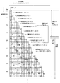
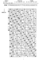
図7は、印刷用紙の上端(先端)近傍において、各ラスタがどのノズルによってどのように記録されていくかを示す説明図である。ここでは、説明を簡単にするため、1列のノズル列のみを使用して説明する。そして、1列のノズル列はそれぞれ3ラスタ分の間隔を開けて11個のノズルを有する。しかし、上端処理で使用されるノズルは、副走査方向下流側の3個のノズルのみである。なお、図7では、印刷に使用されるそれら3個のノズルのみ示されており、使用されないノズルは図示を省略している。
【0047】
図7において、縦に並ぶ1列の升目は、印刷ヘッド28を表している。各升目の中の1〜3の数字が、ノズル番号を示している。明細書中では、これらの番号に「#」を付して各ノズルを表す。図7では、時間とともに副走査方向に相対的に送られる印刷ヘッド28を、順に左から右にずらして示している。太枠で囲まれたノズルが、ラスタにドットを記録するノズルである。
【0048】
図7に示すように、上端処理では、ノズル#1〜#3のみを使用する。ここで、「ノズル#n1〜#n2を使用する」とは、「ノズル#n1〜#n2の各ノズルを必要に応じて使用することができる」という意味である。したがって、ノズル#n1〜#n2のノズル群のうちの少なくとも一部のノズルが使用されていればよく、印刷する画像のデータや、ラスタ上を通過するノズルの組み合わせによっては、他の一部のノズルが使用されない場合もある。また、ある処理において「ノズル#n3〜#n4を使用しない」とは、その処理においてノズル#n3〜#n4の各ノズルを一度も使用しないことを意味する。
【0049】
上端処理においては、3ドットづつの副走査送りを12回繰り返す。この3ドットづつの副走査送りが、特許請求の範囲にいう「第1の副走査モード」に相当する。なお、副走査送り量の単位の「ドット」は、副走査方向の印刷解像度に対応する1ドット分のピッチを意味しており、これはラスタのピッチとも等しい。また、この12回の3ドット送りの間に記録される印刷用紙P上の領域(図7参照)が、特許請求の範囲にいう「上端部」に相当する。
【0050】
上記のような副走査送りを実施すると、一部のラスタを除き、各ラスタはそれぞれ一つのノズルで記録される。例えば、図7において、上から7番目のラスタは、#1のノズルで記録される。また、上から8番目のラスタは、#2のノズルで記録される。
【0051】
また、図7において、上から2,3,6本目のラスタは、印刷の際の主走査においてノズルが通過しない。したがって、これらのラスタについては、ノズルで各画素にドットを形成することができない。よって、第1の画像印刷モードでは、上から6本目までのラスタは、画像を記録するために使用することはしないものとする。すなわち、第1の画像印刷モードにおいて画像を記録するために使用できるラスタは、印刷ヘッド28上のノズルがドットを記録しうるラスタのうち、副走査方向上流の端から7番目以降のラスタとする。この画像を記録するために使用できるラスタの領域を「印刷可能領域」と呼ぶ。また、画像記録のために使用しないラスタの領域を「印刷不可領域」と呼ぶ。図7においては、印刷ヘッド28上のノズルがドットを記録しうるラスタについて、上から順に付した番号を、図の左側に記載している。以降、上端処理のドットの記録を説明する図面においても同様である。
【0052】
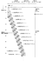
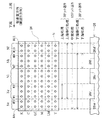
図8は、上端処理、上端移行処理および中間処理において、各ラスタがどのノズルによってどのように記録されていくかを示す説明図である。プリンタ22は、上端処理を行った後、ノズル#1〜#11を使用して上端移行処理を行う。上端移行処理においては、上端処理と同じ3ドットづつの副走査送りを4回繰り返す。この4回の3ドット送りの間に記録される印刷用紙P上の領域(図8参照)が、特許請求の範囲にいう「上端移行部」に相当する。
【0053】
上端移行処理の後、ノズル#1〜#11を使用して、11ドットの定則送りを行ってドットを記録する中間処理に移行する。このように一定の送り量で副走査を行う方式を「定則送り」という。この11ドットづつの副走査送りが特許請求の範囲にいう「第2の副走査モード」に相当する。そして、11ドットづつの副走査送りの間に記録される印刷用紙P上の領域(図8参照)が、特許請求の範囲にいう「中間部」に相当する。
【0054】
また、図8において、上から79番目や80番目のラスタは、印刷の際の主走査において2個のノズルが通過する。そのような、印刷において2個以上のノズルが通過するラスタについては、その中の1個のノズルのみがドットを記録するものとする。ここでは、最後にラスタを通過するノズルが、ドットを記録することとする。これらのラスタは、できるだけ上端移行処理や中間処理に移行した後にそのラスタ上を通過するノズルで記録することが好ましい。上端移行処理、中間処理においては、上端処理に比べて多数のノズルが使用されている。このため、少数のノズルの特性が強く印刷結果に反映されることなく、印刷結果が高画質となることが期待できるからである。
【0055】
以上のような印刷を行う結果、印刷ヘッドがドットを記録しうる最上段のラスタから数えて、7番目のラスタから51番目のラスタまでの領域は、ノズル#1,#2、#3(第4のノズル群Nr)のみで記録されることとなる。そして、52番目以降のラスタは、#1〜#11(ノズル群Nr,Ni,Nh、Nf)を使用して記録される。以下でこれらのラスタと印刷用紙Pとの関係およびその効果について説明する。
【0056】
第1実施例では、印刷用紙の上端まで余白なく画像を記録する。前述のように、第1実施例においては、印刷ヘッド28上のノズルがドットを記録しうるラスタのうち、副走査方向上流の端から7番目以降のラスタ(印刷可能領域)を使用して、画像を記録することができる(図7参照)。したがって、印刷用紙の上端ぎりぎりの位置に上記端から7番目のラスタが位置するように、印刷ヘッド28に対して印刷用紙を配置してドットの記録を開始することとすれば、理論上は、印刷用紙の上端いっぱいまで画像を記録することができる。しかし、副走査送りの際には送り量について誤差が生じる場合がある。また、印刷ヘッドの製造誤差などによりインク滴の吐出方向がずれる場合もある。そのような理由から印刷用紙上へのインク滴の着弾位置がずれた場合についても、印刷用紙の上端に余白が生じないようにすることが好ましい。よって第1の画像印刷モードでは、印刷に使用する画像データDは、印刷ヘッド28上のノズルがドットを記録しうるラスタのうち、副走査方向上流の端から7番目のラスタから設定し、一方で、印刷用紙Pの上端が、副走査方向上流の端から23番目のラスタの位置にある状態から印刷を開始することとする。したがって、印刷開始時の各ラスタに対する印刷用紙上端の想定位置は、図7に示すように、副走査方向上流の端から23番目のラスタの位置である。すなわち、第1実施例のでは、印刷用紙Pの上端Pfを超えて印刷用紙Pの外側まで設定する画像データDの部分の幅(図6参照)は、16ラスタ分である。一方、印刷用紙Pの下端Prを超えて印刷用紙Pの外側ま設定する画像データDの部分の幅は、同様に24ラスタ分である。下端側のラスタについては後述する。
【0057】
図9は、印刷開始時の印刷ヘッド28と印刷用紙Pの関係を示す側面図である。ここでは、プラテン26の中央支持部26cは、印刷ヘッド28の#4のノズルから数えて2ラスタ分上流側の位置から、#6のノズルから数えて2ラスタ分下流側の位置までの範囲R26に設けられている。上流側溝部26fは、#7のノズルから数えて1ラスタ分下流側の位置から、#9のノズルから数えて2ラスタ分前上流側の位置までの範囲に設けられている。そして、下流側溝部26rは、#1のノズルから数えて2ラスタ分下流側の位置から、#3のノズルから数えて2ラスタ分前上流側の位置までの範囲に設けられている。このため、印刷用紙がない状態で各ノズルからインク滴Ipを吐出させた場合でも、ノズル#1,#2、#3のインク滴は下流側溝部26rに着弾し、ノズル#7,#8,#9のインク滴は下流側溝部26rに着弾する。すなわち、それらのノズルからのインク滴はプラテン26の中央支持部26cに着弾することはない。
【0058】
先に図4および図5において示した第4のノズル群Nrが、図9における#1、#2、#3のノズルである。主走査の際にそれらのノズルが通過する部分の下方には、下流側溝部26rが設けられている(図5参照)。そして、図9において、下流側溝部26r上の実線で示す位置に印刷用紙Pの上端Pfがあるときに、印刷が開始される。
【0059】
前述のように、印刷開始時において、印刷用紙Pの上端Pfは、印刷ヘッド28上のノズルがドットを記録しうるラスタのうち、副走査方向上流の端から23番目のラスタの位置にある。すなわち、図9を使用して説明すれば、印刷用紙Pの上端は、#6のノズルから数えて2ラスタ分後ろの位置にあることとなる。しがたって、この状態から印刷を開始することとすると、印刷可能領域の最上段のラスタ(図7において、上から9番目のラスタ)が#3のノズルで記録されるはずであるが、#3のノズル下方にはまだ印刷用紙Pはない。したがって、印刷用紙Pが上流側紙送りローラ25a,25bによって正確に送られていれば、#3のノズルから吐出されたインク滴Ipは、そのまま下流側溝部26rに落下することとなる。印刷可能領域の上から16番目までのラスタ(図7において、上から22番目までのラスタ)を記録する場合についても、同様のことがいえる。
【0060】
しかし、何らかの理由により、印刷用紙Pが本来の送り量よりも多く送られてしまった場合には、印刷用紙Pの上端が印刷可能領域の上から22番目のラスタや、それよりも上のラスタの位置に来てしまう場合もある。第1実施例では、そのような場合でも、#1、#2、#3のノズルがそれらのラスタに対してインク滴Ipを吐出しているため、印刷用紙Pの上端に画像を記録することができ、余白ができてしまうことがない。すなわち、印刷用紙Pが本来の送り量よりも多く送られてしまった場合でも、図9において一点鎖線で示すように、その余分の送り量が16ラスタ分以下である場合には、印刷用紙Pの上端に余白ができてしまうことがない。
【0061】
逆に、何らかの理由により、印刷用紙Pが本来の送り量よりも少なく送られてしまうことも考えられる。そのような場合には、本来印刷用紙があるべき位置に印刷用紙がないこととなり、インク滴Ipが下方の構造物に着弾してしまうこととなる。しかし、図7、図8に示すように、第1の画像印刷モードにおいては、用紙の想定上端位置から29ラスタ(図8において51番目のラスタまで)は、#1、#2、#3のノズルで記録されることとなっている。これらのノズルの下方には下流側溝部26rが設けられており、仮に、インク滴Ipが印刷用紙Pに着弾しなかったとしても、そのインク滴Ipは下流側溝部26rに落下し、吸収部材27rに吸収されることとなる。したがって、インク滴Ipがプラテン26上面部に着弾して、のちに印刷用紙を汚すことはない。すなわち、第1実施例においては、印刷開始時に、印刷用紙Pの上端Pfが想定上端位置よりも後ろにある場合でも、想定上端位置からのずれ量が29ラスタ以下である場合には、インク滴Ipがプラテン26上面部に着弾して、のちに印刷用紙Pを汚すことはない。
【0062】
また、第1実施例では、中間処理においては、すべてノズルを使用して印刷を行っている。このため、中間処理において高速な印刷を行うことができる。
【0063】
さらに、第1実施例では、上端処理の後で中間処理に先立つ上端移行処理において、中間処理と同じく全ノズルを使用して、上端処理と同じ副走査送りを行っている。このため、副走査において逆送りを行うことなく、上端処理から中間処理への移行をスムーズに行うことができる。このため、印刷結果の品質が高い。
【0064】
以上に説明した効果は、印刷用紙Pの上端を印刷する際、印刷用紙Pの上端が下流側溝部26rの開口上にあるときに、第4のノズル群Nr(第4の部分ドット形成要素群)の少なくとも一部からインク滴を吐出させて、印刷用紙P上にドットを形成することによって得られる。
【0065】
以上で説明したような、第4のノズル群Nr(ノズル#1,#2,#3)による上端処理、およびノズル群Nr,Ni,Nh,Nf(ノズル#1〜#11)による上端移行処理および中間処理は、CPU41(図3参照)によって行われる。すなわち、CPU41が特許請求の範囲にいう「上端印刷部」、「上端移行印刷部」、「中間印刷部」として機能する。これらCPU41の機能部としての上端印刷部41p、上端移行印刷部41q、と中間印刷部41rを図3に示す。
【0066】
(2)下端移行処理および下端処理:
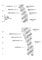
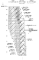
図10ないし図12は、下端移行処理および下端処理において、各ラスタがどのノズルによってどのように記録されていくかを示す説明図である。第1実施例では、図10に示すように、中間処理において、全ノズルを使用し、11ドットの定則送りを繰り返したのち、下端移行処理において、#1〜#9ノズル(ノズル群Nr,Ni,Nh)を使用して、3ドットづつの送りを5回行ってドットを形成する。すなわち、下端移行処理においては、第1のノズル群Nf(ノズル#10,#11)は使用しない。この5回の3ドット送りの間に記録される印刷用紙P上の領域(図10、図11参照)が、特許請求の範囲にいう「下端移行部」に相当する。
【0067】
そして、図11および図12に示すように、下端移行処理の後、下端処理において、#7〜#9ノズル(第2のノズル群Nh)のみを使用して、3ドットづつの送りを17回行ってドットを形成する。この3ドットづつの定則送りが、特許請求の範囲にいう「第3の副走査モード」に相当する。そして、この17回の3ドット送りの間に記録される印刷用紙P上の領域(図11、図12参照)が、特許請求の範囲にいう「下端部」に相当する。なお、印刷用紙Pの「上端部」、「上端移行部」、「中間部」、「下端移行部」、「下端部」は、互いに一部重複するものの印刷用紙Pの表面部において上から順に並んで位置している。
【0068】
このような送りを行うと、主走査方向に沿った各ラスタは、一部のものを除いてそれぞれ1個のノズルで記録される。なお、図10ないし図12においては、印刷ヘッド28上のノズルがドットを記録しうるラスタについて、下から順に付した番号を、図の右側に記載している。以降、下端処理のドットの記録を説明する図面において同様である。
【0069】
図12において、最下段から2,3,6本目のラスタは、印刷の際の主走査においてノズルが通過しない。したがって、印刷用紙の下端部分における印刷可能領域は、最下段から7本目以上のラスタの領域である。
【0070】
また、図10において、下から80番目や81番目のラスタなどは、印刷の際の主走査において2個以上のノズルが通過する。図11の下から59番目や63番目のラスタなども同様である。そのような、印刷において2個以上のノズルが通過するラスタについては、最初にラスタを通過するノズルが、ドットを記録することとする。このようなラスタについては、中間処理、中間処理や下端移行処理においてそのラスタ上を通過するノズルで記録することが好ましい。中間処理、下端移行処理においては、下端処理に比べて多数のノズルが使用されている。このため、少数のノズルの特性が強く印刷結果に反映されることなく、印刷結果が高画質となることが期待できるからである。
【0071】
以上のような印刷を行うと、図11および図12に示すように、印刷ヘッドがドットを記録しうる最下段のラスタから数えて、58番目のラスタまでの領域は、ノズル#7,#8,#9(第2のノズル群Nh)のみで記録されることとなる。そして、59番目以上のラスタは、#1〜#11(ノズル群Nr,Ni,Nh,Nf)を使用して記録される。以下でこれらのラスタと印刷用紙Pとの関係およびその効果について説明する。
【0072】
第1の画像印刷モードでは、上端の場合と同様、下端についても余白なく画像を記録する。前述のように、第1実施例においては、印刷ヘッド28上のノズルがドットを記録しうるラスタのうち、副走査方向下流の端から7番目以上のラスタ(印刷可能領域)を使用して、画像を記録することができる。しかし、副走査送りの際に送り量について誤差が生じる場合等を考慮して、副走査方向下流の端から31番目のラスタから印刷用紙上に記録するものとする。すなわち、印刷用紙の下端が、副走査方向上流の端から31番目のラスタの位置にある状態で、30番目以下のラスタについてもインク滴Ipの吐出を行い、印刷の際の最後の主走査を行う。したがって、印刷終了時の各ラスタに対する印刷用紙下端の想定位置は、図11に示すように、副走査方向下流の端から31番目のラスタの位置である。
【0073】
図13は、印刷用紙Pの下端部Prの印刷をする際の上流側溝部26fと印刷用紙Pの関係を示す平面図である。図13において、印刷ヘッド28の斜線で示した部分の第2のノズル群Nhが、#7、#8、#9のノズルである。主走査の際にそれらのノズルが通過する部分の下方には、上流側溝部26fが設けられている。そして、上流側溝部26f上の一点鎖線で示す位置に印刷用紙Pの下端Prがあるときに、実際の印刷用紙Pへのドットの記録を終了する。
【0074】
図14は、印刷用紙Pの下端部Prの印刷をする際の印刷ヘッド28と印刷用紙Pの関係を示す側面図である。前述のように、印刷用紙Pの下端部Prの印刷をする際、印刷用紙Pの下端Prは、印刷ヘッド28上のノズルがドットを記録しうるラスタのうち、副走査方向下流の端から31番目のラスタの位置にある(図12参照)。すなわち、印刷用紙Pの下端のラスタが記録されるとき、印刷用紙Pの下端は、#9のノズルの直下にあることとなる。したがって、その後、副走査送りを行ってノズル#7〜#9からインク滴を吐出しても、吐出されたインク滴Ipは、そのまま上流側溝部26fに落下することとなる。
【0075】
しかし、何らかの理由により、印刷用紙Pが本来の送り量よりも少なく送られてしまった場合には、#7、#8、#9のノズルが印刷用紙Pの下端Prを超えて設定されるラスタ(図12において、下から7番目から30番目までのラスタ)に対してインク滴Ipを吐出しているため、印刷用紙Pの下端Prに画像を記録することができ、余白ができてしまうことがない。すなわち、その不足の送り量が24ラスタ分以下である場合には、印刷用紙Pの下端に余白ができてしまうことがない。
【0076】
そして、用紙の想定下端位置から上の28ラスタ(図11において、下から31番目から62番目のラスタ)は、#7、#8、#9のノズルで記録されることとなっている。よって、何らかの理由により、印刷用紙Pが本来の送り量よりも多く送られてしまった場合にも、吐出されたインク滴Ipは上流側溝部26fに落下し、プラテン26上面部に着弾することがない。
【0077】
以上に説明した効果は、印刷用紙Pの下端を印刷する際、印刷用紙Pの下端が上流側溝部26fの開口上にあるときに、第2のノズル群Nh(第2の部分ドット形成要素群)の少なくとも一部からインク滴を吐出させて、印刷用紙P上にドットを形成することによって得られる。
【0078】
また、第1実施例では、中間処理においては、すべてノズルを使用して印刷を行っている。このため、中間処理において高速な印刷を行うことができる。
【0079】
さらに、第1実施例では、中間処理の後で下端処理に先立つ下端移行処理において、ノズル群Nh,Ni,Nr(ノズル#1〜#9)のみを使用している。すなわち、下端処理において使用する第2のノズル群Nhよりも上流側に位置する第1のノズル群Nf(ノズル#10,#11)を使用していない。このため、副走査において逆送りを行うことなく、中間処理から下端処理への移行をスムーズに行うことができる。このため、印刷結果の品質が高い。
【0080】
以上で説明したような、ノズル群Nh,Ni,Nr(ノズル#1〜#9)による下端移行処理、および第2のノズル群Nh(ノズル#7,#8,#9)による下端処理は、CPU41(図3参照)によって行われる。すなわち、CPU41が特許請求の範囲にいう「下端移行印刷部」、「下端印刷部」として機能する。これらCPU41の機能部としての下端移行印刷部41sおよび下端印刷部41tを図3に示す。
【0081】
C.第2実施例:
図15は、第2実施例における印刷ヘッド28aと上流側溝部26faおよび下流側溝部26raの関係を示す側面図である。ここでは、1列のノズル列が48個のノズルを有する態様の印刷装置について説明する。第1実施例では副走査送りは定則送りを行ったが、この第2実施例では、変則送りを行う。「変則送り」とは、異なる送り量を組み合わせて副走査を行う方式である。また、第2実施例では、各ラスタを2度の主走査によって異なる二つのノズルで記録する。このように、一つのラスタ内の画素を複数のノズルで分担して印刷する方式を「オーバーラップ印刷」という。オーバーラップ印刷においては、一つのラスタは、印刷ヘッドに対する印刷用紙の副走査方向の位置が互いに異なる複数回の主走査において、そのラスタ上を通過する複数のノズルによってドットを記録される。
【0082】
第2実施例の印刷装置では、上流側支持部26sfは、副走査方向について、ノズル#35〜#48(第1のノズル群Nfa)に向かい合う位置に設けられる。また、上流側溝部26faは、ノズル#31〜#34(第2のノズル群Nha)と向かい合う位置に設けられる。中央支持部26caは、ノズル#6〜#30(第3のノズル群Nia)と向かい合う位置に設けられる。そして、下流側溝部26raは、ノズル#1〜#5(第4のノズル群Nra)と向かい合う位置に設けられる。他の点は第1実施例の印刷装置と同様の構成である。
【0083】
第2実施例における第1のノズル群Nfaが特許請求の範囲にいう「第1の部分ドット形成要素群」に相当し、第2のノズル群Nhaが特許請求の範囲にいう「第2の部分ドット形成要素群」に相当する。第3のノズル群Niaが特許請求の範囲にいう「第3の部分ドット形成要素群」に相当し、第4のノズル群Nraが特許請求の範囲にいう「第4の部分ドット形成要素群」に相当する。なお、ここでは、各ノズルアレイの部分ドット形成要素群をまとめて取り扱って、それぞれノズル群Nfa,Nha,Nia,Nraとしている。
【0084】
(1)上端処理、上端移行処理および中間処理:
図16は、第2実施例の上端処理において、各ラスタがどのノズルによってどのように記録されていくかを示す説明図である。図16に示すように、第2実施例の上端処理においては、第4のノズル群Nra(ノズル#1〜#5)を使用して、2ドット、3ドット、2ドット、2ドット、1ドット、2ドットの送りをその順に72回繰り返す。ただし、実際には第4のノズル群Nraのうち、ノズル#5は使用されない。また、副走査送りの最初には、はじめの2ドット送りを行わずに、3ドット、2ドット、2ドット、1ドット、2ドットの副走査送りを行う。この上端処理で行う、2ドット、3ドット、2ドット、2ドット、1ドット、2ドットの変則送りが特許請求の範囲にいう「第1の副走査モード」に相当する。なお、図において太枠で囲まれたノズルが、ラスタにドットを記録するノズルである。
【0085】
上端処理の後、2ドット、3ドット、2ドット、2ドット、1ドット、2ドットの変則送りのまま、#1〜#48の全ノズル(ノズル群Nra,Nia,Nha,Nfa)を使用して上端移行処理を行う。上端移行処理において、副走査送りは合計12回行われる。
【0086】
図17は、第2実施例の中間処理において、各ラスタがどのノズルによってどのように記録されていくかを示す説明図である。上端移行処理の後、図17に示すような中間処理に移行して、#1〜#48の全ノズル(ノズル群Nra,Nia,Nha,Nfa)を使用して、20ドット、27ドット、22ドット、28ドット、21ドット、26ドットの変則送りが繰り返される。この変則送りが、特許請求の範囲にいう「第2の副走査モード」に相当する。なお、中間処理における「第2の副走査モード」は、最大の送り量が、上端処理における最大の副走査送り量よりも大きいものであれば、他の送り方でもよい。
【0087】
上記のような送りが行われる結果、各ラスタが2度の主走査によって二つのノズルで記録される。なお、図16に示すように、上から25番目や28番目のラスタのような、3以上のノズルが通過するラスタについては、最後にラスタを通過する2個のノズルのみがドットを記録するものとする。
【0088】
図16に示すように、第2実施例では、印刷ヘッド28上のノズルがドットを記録しうるラスタのうち、副走査方向上流の端から19番目以降のラスタ(印刷領域)を使用して、画像を記録することができる。よって、印刷に使用する画像データDは、副走査方向上流の端から19番目のラスタから設定する。しかし、第1実施例と同様の理由から、印刷は、印刷用紙Pの上端が副走査方向上流の端から19番目の位置にあるときではなく、より後にあるときから開始する。すなわち、第2実施例においても、想定される印刷用紙Pの上端の位置を越えて画像データDが設けられる。
【0089】
第2実施例においては、中間処理において全ノズルを使用して印刷を行う。このため、一部のノズルを使用しない場合に比べて高速に印刷を行うことができる。そして、第2実施例においては、上端処理と中間処理との間に、中間処理と同じく全ノズルを使用し、上端処理と同じ送り(2ドット、3ドット、2ドット、2ドット、1ドット、2ドットの送り)を行う上端移行処理を行っている。このため、上端処理から中間処理に移行する際に逆送りが必要なく、スムーズに印刷を行うことができる。このため、印刷結果の品質が高い。
【0090】
(2)下端移行処理および下端処理:
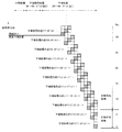
図18は、第2実施例の中間処理、下端移行処理および下端処理において、各ラスタがどのノズルによってどのように記録されていくかを示す説明図である。図の上段に示す表は、それぞれの副走査送り量を示している。第2実施例では、図18に示すように、中間処理において、全ノズルを使用して20ドット、27ドット、22ドット、28ドット、21ドット、26ドットの変則送りを繰り返したのち、下端移行処理においてノズル#1〜#34(ノズル群Nra,Nia,Nha)を使用して2ドット、3ドット、2ドット、2ドット、1ドット、2ドットの送りをその順に8回繰り返す(2ドット、3ドット、2ドット、2ドット、1ドット、2ドット、2ドット、3ドットの8回)。そして、その後、下端処理において、ノズル#31〜#34(第2のノズル群Nha)のみを使用して、引き続き2ドット、3ドット、2ドット、2ドット、1ドット、2ドットの送りを繰り返す。この2ドット、3ドット、2ドット、2ドット、1ドット、2ドットの変則送りが、特許請求の範囲にいう「第3の副走査モード」に相当する。以上のような印刷を行うと、各ラスタは、2度の主走査で2個のノズルで記録される。なお、3個以上のノズルが通過するラスタについては、そのうちの2個のノズルのみがドットを記録する。その結果、たとえば、下端処理において、ある主走査では、ノズル#31〜#34のうちで使用されないノズルが存在する場合もある。
【0091】
以上で説明した第2実施例では、中間処理と下端処理との間に、第2のノズル群Nhaよりも上流側に位置する第1のノズル群Nfa(ノズル#35〜#48)を使用せずに、下端処理と同じ送り(2ドット、3ドット、2ドット、2ドット、1ドット、2ドットの変則送り)を行う下端移行処理を行っている。このため、中間処理から下端処理に移行する際に逆送りが必要なく、スムーズに印刷を行うことができる。このため、印刷結果の品質が高い。
【0092】
さらに、第2実施例では、上端処理、上端移行処理、中間処理、下端移行処理、下端処理を通じて、変則送りを行っている。このため、定則送りを行う場合に比べて印刷結果の品質が高い。また、オーバーラップ印刷を行っているため、オーバーラップ印刷を行わない場合に比べて印刷結果の品質が高い。
【0093】
D.第3実施例:
(1)第3実施例の概要:
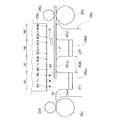
図19は、第3実施例における印刷ヘッド28上の使用ノズルの変化を示す説明図である。図19においては、図1と同様、左側に印刷ヘッド28の下面を示し、右側に、印刷ヘッド28上の各ノズルに対応するプラテン26の構成を側面図として示している。第3実施例のプリンタでは、印刷ヘッド28の各色ノズル列K,C,LC,M,LM,Yは、それぞれ下流側支持部26srと向かい合う位置にノズル#A,#Bを有している。これらのノズル#A,#Bは、第5のノズル群Ntに分類される。この第5のノズル群Ntは、第4のノズル群Nrの下流側に位置し、下流側支持部26srが特許請求の範囲にいう「第3の支持部」に相当する。第3実施例のプリンタのハードウェア構成は、他の点は、第1実施例のプリンタと同様である。なお、各ノズル列内で下流から上流に向けて並ぶノズル#A〜#11の13個のノズルは、一定のノズルピッチk=4で配されている。
【0094】
第3実施例の印刷では、中間処理と下端移行処理において、ノズル#A,#Bが使用される点で、第1実施例の印刷とは異なる。他の点は、第1実施例における印刷と同様である。
【0095】
第3実施例のプリンタは、印刷用紙の上端部については、上端が下流側溝部26r上にあるときに、下流側溝部26rと向かい合う第4のノズル群Nrのみで印刷を行う(上端処理)。そして、印刷用紙の下端部については、下端が上流側溝部26f上にあるときに、上流側溝部26fと向かい合う第2のノズル群Nhのみで印刷を行う(下端処理)。また、印刷用紙の中間部は、ノズル群Nt(ノズル#A,#B)を含む全ノズル群を使用して印刷を行う(中間処理)。
【0096】
さらに、上端処理と中間処理の間に、上端処理と同じ副走査送りを行い、Nf,Nh,Ni,Nrを使用して印刷を行う上端移行処理を行う。上端移行処理においては、ノズル群Ntは使用しない。また、中間処理と下端処理の間には、下端処理と同じ副走査送りを行い、ノズル群Nh,Ni,Nr,Ntを使用して印刷を行う下端移行処理を行う。下端移行処理においては、ノズル群Nfは使用しない。
【0097】
(2)上端処理、上端移行処理および中間処理:
図20は、印刷用紙の上端(先端)近傍において、各ラスタがどのノズルによってどのように記録されていくかを示す説明図である。図21は、上端処理、上端移行処理および中間処理において、各ラスタがどのノズルによってどのように記録されていくかを示す説明図である。第3実施例において上端処理で使用されるノズルは、下流側溝部26rと向かい合う位置にあるノズル#1〜#3のみである。なお、図20では、印刷に使用されるそれら3個のノズルのみノズル番号を示し、ノズル#A,#Bを含む使用されないノズルは「*」を付して示している。また、印刷可能領域の各ラスタの記録を担当するノズルについては、太枠で囲われている。
【0098】
上端処理においては、第1実施例と同様、3ドットづつの副走査送りを12回繰り返す。この3ドットづつの副走査送りが、特許請求の範囲にいう「第1の副走査モード」に相当する。この12回の3ドット送りの間に記録される印刷用紙P上の領域(図20参照)が、特許請求の範囲にいう「上端部」に相当する。なお、第3実施例においては、印刷可能領域は上から15番目以降のラスタの領域であり、14番目までのラスタの領域は、印刷不可能領域である。
【0099】
図20に示すように、第3実施例においては、印刷用紙の想定上端位置は30番目のラスタの位置である。一方、第3実施例においては、上から15番目のラスタから50番目のラスタ(図20において図示せず)までの領域は、ノズル#1〜#3のみを使用する上端処理において記録される。すなわち、30番目のラスタの位置にある印刷用紙の上端を挟んで、印刷用紙の外側(上流側)にある15ラスタと、内側(下流側)にある21ラスタは、下流側溝部26rと向かい合う位置にあるノズル#1〜#3のみ使用する主走査において記録される。それらの主走査においては、他のノズルからはインク滴は吐出されない。よって、このような上端処理をおこなうことで、プラテンを汚すことなく、印刷用紙の上端まで余白なく印刷を行うことができる。
【0100】
第3実施例のプリンタは、上端処理を行った後、ノズル#1〜#11を使用して上端移行処理を行う(図19および図21参照)。上端移行処理においては、上端処理と同じ3ドットづつの副走査送りを4回繰り返す。この4回の3ドット送りの間に記録される印刷用紙P上の領域(図21参照)が、特許請求の範囲にいう「上端移行部」に相当する。
【0101】
上端移行処理の後、ノズル#A〜#11の全ノズルを使用して、13ドットの定則送りを行ってドットを記録する中間処理に移行する。この13ドットづつの副走査送りが特許請求の範囲にいう「第2の副走査モード」に相当する。そして、13ドットづつの副走査送りの間に記録される印刷用紙P上の領域(図21参照)が、特許請求の範囲にいう「中間部」に相当する。このような上端移行処理を行うことで、上端処理から中間処理へスムーズに移行することができる。また、中間処理では全ノズルを使用して印刷を行うので、高速に印刷を行うことができる。
【0102】
(3)下端移行処理および下端処理:
図22および図23は、下端移行処理および下端処理において、各ラスタがどのノズルによってどのように記録されていくかを示す説明図である。第3実施例では、中間処理において、全ノズルを使用し、13ドットの定則送りを繰り返しす。その後、下端移行処理において、#A〜#9ノズル(ノズル群Nt,Nr,Ni,Nh)を使用して、3ドットづつの送りを5回行ってドットを形成する(図19参照)。下端移行処理においては、第1のノズル群Nf(ノズル#10,#11)は使用しない。この5回の3ドット送りの間に記録される印刷用紙P上の領域(図22および図23参照)が、特許請求の範囲にいう「下端移行部」に相当する。
【0103】
図23に示すように、下端移行処理の後、下端処理において、#7〜#9ノズル(第2のノズル群Nh)のみを使用して、3ドットづつの送りを13回行ってドットを形成する(図19参照)。この3ドットづつの定則送りが、特許請求の範囲にいう「第3の副走査モード」に相当する。そして、この13回の3ドット送りの間に記録される印刷用紙P上の領域(図22および図23参照)が、特許請求の範囲にいう「下端部」に相当する。第3実施例では、下端処理に先立って下端移行処理を行っているため、中間処理から下端処理にスムーズに移行することができる。
【0104】
図23に示すように、第3実施例においては、印刷用紙の下端部分における印刷不可能領域は、印刷ヘッドがドットを記録しうる最下段のラスタから数えて14番目のラスタまでである。そして、印刷可能領域は、最下段のラスタから15番目以上のラスタの領域である。
【0105】
図23に示すように、第3実施例においては、印刷用紙の想定下端位置は、印刷ヘッドがドットを記録しうる最下段のラスタから数えて31番目のラスタの位置である。第3実施例においては、下から15番目のラスタから47番目のラスタまでの領域は、ノズル#7〜#9のみを使用する下端処理において記録される。すなわち、印刷用紙の下端を挟んで外側(下流側)にある16ラスタと、内側(上流側)にある17ラスタは、上流側溝部26fと向かい合う位置にあるノズル#7〜#9のみで記録される。よって、このような下端処理をおこなうことで、プラテンを汚すことなく、印刷用紙の上端まで余白なく印刷を行うことができる。
【0106】
(3)各ノズルの性能の印刷結果への影響:
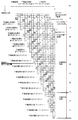
図24は、副走査方向に配された各ノズルの性能の違いを示したグラフである。図24(a)は、副走査方向に配された各ノズルのインク滴の吐出速度を示したグラフである。ここでは、ノズル列中でのノズルの位置と性能の関係を分かりやすく示すために、一列中に48個のノズルを有するノズル列についてのグラフを示す。図24(a)に実線および一点鎖線で示すように、ノズルのインク滴の吐出速度Vkの設計値Vk0からのばらつきは、端のノズルほど大きい傾向にある。すなわち、中央のノズル#24の近辺のノズルについては、比較的吐出速度は設計値Vk0に近いが、副走査方向の端のノズル#1やノズル#48の近辺のノズルは比較的吐出速度の設計値Vk0からのずれが大きい。図において実線で示すように、端のノズルほどインク滴の吐出速度Vkが設計値Vk0よりも大きくなる場合もあり、また、一点差線で示すように、端のノズルほどインク滴の吐出速度が設計値よりも小さくなる場合もある。さらに、一方の端については、端のノズルほどインク滴の吐出速度が設計値よりも小さくなり、他方の端については、端のノズルほど吐出速度が大きくなる場合もある。
【0107】
また、インク滴の吐出速度のばらつきだけでなく、各ノズルからインク滴を吐出する向きのばらつきも、副走査方向の端のノズルほど大きくなる場合がある。このように、様々な理由によって、副走査方向の端のノズルほど印刷用紙上のドット形成位置のズレが大きくなる場合がある。
【0108】
図24(b)は、副走査方向に配された各ノズルから吐出されるインク滴の重量を示したグラフである。図24(b)においても、ノズル列中でのノズルの位置と性能の関係を分かりやすく示すために、一列中に48個のノズルを有するノズル列についてのグラフを示している。インク滴の重量Iwについても、端のノズルほど設計値Iw0からのばらつきが大きい。そのばらつきの傾向については、図24(b)において実線で示すように、端のノズルほどインク滴の重量が大きくなる場合もあり、また、一点差線で示すように、端のノズルほどインク滴の重量が小さくなる場合もある。また、一方の端については、端のノズルほどインク滴の重量が小さくなり、他方の端については、端のノズルほど重量が大きくなる場合もある。インク滴の重量がばらつくと、印刷用紙上のドットの大きさがばらつくこととなる。したがって、印刷において端部近辺のノズルを使用することで、印刷結果の品質が低下する可能性がある。
【0109】
このような印刷装置傾向を有するを使用して上端処理や下端処理を行う際には、端部のノズルを使用しないことが好ましい。全ノズル中の一部のノズルのみで印刷を行う上端処理や下端処理において、端部に位置するノズルのみを使用すると、全ノズルを使用する中間処理などに比べて、特に印刷結果の品質が悪くなると考えられるからである。
【0110】
また、端部の印刷を行う際には、印刷用紙は、上流側紙送りローラ25p,25qと下流側紙送りローラ25r,25sのいずれか一方のみで指示されている場合がある。また、印刷用紙Pの端部Pf,Prが溝上にあり、支持部によって下から支持されていないこともある。このようなときには、印刷用紙はわずかながら上方にふくらんだり下方に撓んだりしている可能性がある。このため、インク滴が正確に吐出されても印刷用紙上の正確な位置に着弾しない可能性がある。よって、インク滴の吐出が正確に行われない場合には、印刷用紙の中央部の印刷にくらべてよりドット形成位置が大きくずれてしまう可能性がある。よって、印刷用紙の端部の印刷においては、インク滴の吐出を高精度に行う要請が、印刷用紙の中央部の印刷に比してさらに高い。
【0111】
第3実施例では、下流の端に位置するノズル#A,#Bは、上端処理において使用されない。そして、印刷用紙の上端部を印刷するノズル#1〜#3(ノズル群Nr)は、ノズル#A,#B(ノズル群Nt)に対してドット形成位置のズレやドットの大きさの誤差が小さいと考えられるノズルである。このため、印刷用紙の上端部の印刷結果の品質がより高いものとなる可能性が高い。また、上流の端に位置するノズル#11,#12(ノズル群Nf)は、下端処理において使用されない。そして、印刷用紙の下端部を印刷するノズル#7〜#9(ノズル群Nh)は、ノズル#11,#12(ノズル群Nf)に対してドット形成位置のズレやドットの大きさの誤差が小さいと考えられるノズルである。このため、印刷用紙の下端部の印刷結果の品質がより高いものとなる可能性が高い。
【0112】
なお、個々のノズルの印刷用紙上のドット形成位置のズレやインク滴吐出速度のズレは、図24(a),(b)に示したようなグラフのカーブに必ずしも一致する必要はない。すなわち、ノズル群Nrのノズルの印刷媒体上のドット形成位置の平均位置ズレが、ノズル群Ntのドット形成位置の平均位置ズレよりも小さければ、第3実施例のような上端処理を行うことで、印刷結果の品質をより高くすることができる。また、ノズル群Nhのノズルの印刷媒体上のドット形成位置の平均位置ズレが、ノズル群Nfのドット形成位置の平均位置ズレよりも小さければ、第3実施例のような下端処理を行うことで、印刷結果の品質をより高くすることができる。
【0113】
同様に、ノズル群Nrのノズルが、ノズル群Ntのノズルよりも、インク滴の吐出速度の平均ズレ量が小さいものであれば、結果として、上端処理において印刷媒体上のドット形成位置の平均位置ズレ量が小さいノズルを使用して、高品質な印刷を行うことができる。そして、ノズル群Nhのノズルが、ノズル群Nfのノズルよりも、インク滴の吐出速度の平均ズレ量が小さいものであれば、結果として、下端処理において印刷媒体上のドット形成位置の平均位置ズレ量が小さいノズルを使用して、高品質な印刷を行うことができる。なお、このような効果は、下端処理において、最上流に位置するノズル群Nfを使用しないでノズル群Nhを使用する、第1実施例および第2実施例においても同様に発揮される。
【0114】
(4)ドット形成位置のズレ量の決定:
図25は、振動板検査法の原理を示す説明図である。図25には、ドット抜け検査部52を構成する振動板52aとマイクロフォン52bも描かれている。各ノズルnに設けられたピエゾ素子PEは、ノズルnまでインクを導くインク通路80に接する位置に設置されている。ピエゾ素子PEにインク滴吐出信号が送られると、ピエゾ素子PEはインク通路80の一側壁を変形させ、インク滴Ipをノズルnの先端から吐出させる。そのインク滴Ipが振動板52aに到達すると、振動板52aが振動する。マイクロフォン52bは、この振動板52aの振動を電気信号に変換する。この電気信号が検出された時刻と、ピエゾ素子PEにインク滴吐出信号が送られた時刻との間の時間差を求めれば、実質的に、インク滴Ipの飛翔時間tiを求めることができる。
【0115】
ドット形成位置のズレは、次のようにして計算することができる。ノズルnから振動板52aまでの距離をLsとすると、インク滴Ipの飛翔速度Vkは、次の式で計算できる。このVkを各ノズルについて並べて記録すると、図24(a)のようなグラフとなる。
【0116】
Vk=Ls/ti ・・・(1)
【0117】
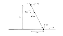
図26は、インク滴を吐出するノズルの位置と、インク滴の着弾位置の関係を示す説明図である。印刷ヘッド28上のノズルnは、主走査によって図の左から右に向かって速度Vsで送られる。印刷の際のノズルnから印刷用紙Pまでの距離をLpとすると、Lpを先に求めたVkで割ることで、インク滴Ipが吐出されてから印刷用紙Pに着弾するまでの時間tpが求められる。
【0118】
tp=Lp/Vk ・・・(2)
【0119】
さらに、インク滴を吐出した時のノズルの主走査方向の位置と、インク滴の着弾位置との主走査方向についての差Dmは、印刷ヘッド28の主走査速度Vsから、次の式で求めることができる。
【0120】
Dm=Vs×tp ・・・(3)
【0121】
印刷ヘッド28のノズルの中から基準ノズルを一つ定めて、そのノズルのインク滴の吐出位置とインク滴の着弾位置の差Dmを、Dm0とする。すると、各ノズルのドット形成位置の主走査方向のズレDd(i)(iはノズル番号)は、次の式で定められる。なお、Dm(i)は、ノズルiのインク滴の吐出位置とインク滴の着弾位置の差である。
【0122】
Dd(i)=Dm(i)−Dm0 ・・・(4)
【0123】
ノズル群のドット形成位置の平均ズレ量は、このDdをノズル群ごとに平均して求めることができる。なお、ここでは、基準となるノズルを一つ決めて、そのノズルのインク滴の吐出位置とインク滴の着弾位置の差Dmを基準値Dm0とした。しかし、Dm0は他の方法で定めることもできる。たとえば、全てのノズルまたは所定の一部のノズルのDm(i)の平均値をDm0とすることもできる。
【0124】
また、ここでは、ドット形成位置のズレ量は、インク滴の飛翔時間から計算して求めたが、他の方法で求めることもできる。例えば、複数のノズルに、同一のタイミングでインク滴吐出信号を送る。そして、実際に印刷用紙にドットを形成させて、そのドット形成位置を測定することとしてもよい。例えば、印刷ヘッド28のノズルの中から、基準となるノズルを一つ定める。他のノズルが形成するドットの本来の位置(想定位置)は、その基準ノズルが形成したドットの位置から設計値に基づいて求められるはずである。その想定位置と実際のドットの位置とのズレを、主走査方向および副走査方向について測定して、ドット形成位置のズレ量を求めることができる。この場合、光学センサで各ドットの位置を自動的に読みとることが好ましい。
【0125】
ドットの位置とのズレを、主走査方向および副走査方向について測定したのち、各ノズル群のドット形成位置ズレの平均を求めて大小を評価する際には、ドットの想定位置と実際の位置との間の距離Dcを基準とすることができる。主走査方向のドット形成位置ズレ量をDdとし、副走査方向のドット形成位置ズレ量をDeとしたとき、ドットの想定位置と実際の位置の距離Dcは次の式で定めることができる。
【0126】
Dc=(Dd2+De2)1/2 ・・・(5)
【0127】
このような態様においては、主走査方向のドット形成位置ズレだけでなく、副走査方向のドット形成位置ずれも考慮することができる。ただし、実際にプリンタにドットを形成させてドットの形成位置を測定してズレ量を評価する場合にも、主走査方向または副走査方向のいずれか一方のズレのみを基準とすることもできる。
【0128】
E.変形例:
なお、この発明は上記の実施例や実施形態に限られるものではなく、その要旨を逸脱しない範囲において種々の態様において実施することが可能であり、例えば次のような変形も可能である。
【0129】
E1.変形例1:
第1実施例と第3実施例では、第1の副走査モードでは3ドットづつの定則送りを行い、第2実施例の第1の副走査モードでは2ドット、3ドット、2ドット、2ドット、1ドット、2ドットの変則送りを行った。しかし、上端処理と下端処理の送りはこれに限られるものではなく、ノズル列中のノズル数やノズルピッチに応じて、他の定則送りや変則送りとすることもできる。すなわち、最大の副走査送り量が中間処理における最大の副走査送り量よりも小さいものであればよい。ただし、上端処理の副走査送りの送り量が小さいほど、より副走査方向の下流側のノズルで印刷用紙の上端を記録することができる。そのため、より下流側溝部を狭くすることができ、印刷用紙を支えるプラテン上面を広く取ることができる。同様に、下端処理の副走査送りの送り量が小さいほど、より上流側のノズルで印刷用紙の上端を記録することができる。そのため、より上流側溝部を狭くすることができ、印刷用紙を支えるプラテン中央部の上面を広く取ることができる。
【0130】
また、上記実施例においては、第1の副走査モードの送りと第3の副走査モードの送りは同じであったが、両者は必ずしも同じである必要はない。例えば、第2実施例のプリンタにおいて、第1の副走査モードの送りを、2ドット、3ドット、2ドット、2ドット、1ドット、2ドットの変則送りとし、第3の副走査モードの送りを2ドット、1ドット、2ドット、3ドット、2ドット、2ドットの変則送りとしてもよい。そして、必ずしも、第1実施例および第3実施例のように、上端処理から下端処理に至る印刷を通して定則送りを行う必要はなく、第2実施例のように、上端処理から下端処理に至る印刷を通して変則送りを行う必要はない。第1の副走査モードの送りと第3の副走査モードの送りは定則送りとし、第2の副走査モードは変則送りとしてもよい。すなわち、第1の副走査モードと第3の副走査モードにおける送りの、最大の副走査送り量が、第2の副走査モードの最大の副走査送り量よりも小さいような送りであればよい。
【0131】
E2.変形例2:
この発明はカラー印刷だけでなくモノクロ印刷にも適用できる。また、この発明は、インクジェットプリンタのみでなく、一般に、複数のドット形成要素アレイを有する記録ヘッドを用いて記録媒体の表面に記録を行うドット記録装置に適用することができる。ここで、「ドット形成要素」とは、インクジェットプリンタにおけるインクノズルのように、ドットを形成するための構成要素を意味する。
【0132】
E3.変形例3:
上記実施例において、ハードウェアによって実現されていた構成の一部をソフトウェアに置き換えるようにしてもよく、逆に、ソフトウェアによって実現されていた構成の一部をハードウェアに置き換えるようにしてもよい。例えば、CPU41(図3)の機能の一部をホストコンピュータ90が実行するようにすることもできる。
【0133】
このような機能を実現するコンピュータプログラムは、フロッピディスクやCD−ROM等の、コンピュータ読み取り可能な記録媒体に記録された形態で提供される。ホストコンピュータ90は、その記録媒体からコンピュータプログラムを読み取って内部記憶装置または外部記憶装置に転送する。あるいは、通信経路を介してプログラム供給装置からホストコンピュータ90にコンピュータプログラムを供給するようにしてもよい。コンピュータプログラムの機能を実現する時には、内部記憶装置に格納されたコンピュータプログラムがホストコンピュータ90のマイクロプロセッサによって実行される。また、記録媒体に記録されたコンピュータプログラムをホストコンピュータ90が直接実行するようにしてもよい。
【0134】
この明細書において、ホストコンピュータ90とは、ハードウェア装置とオペレーションシステムとを含む概念であり、オペレーションシステムの制御の下で動作するハードウェア装置を意味している。コンピュータプログラムは、このようなホストコンピュータ90に、上述の各部の機能を実現させる。なお、上述の機能の一部は、アプリケーションプログラムでなく、オペレーションシステムによって実現されていても良い。
【0135】
なお、この発明において、「コンピュータ読み取り可能な記録媒体」とは、フレキシブルディスクやCD−ROMのような携帯型の記録媒体に限らず、各種のRAMやROM等のコンピュータ内の内部記憶装置や、ハードディスク等のコンピュータに固定されている外部記憶装置も含んでいる。
【図面の簡単な説明】
【図1】本発明の実施の形態におけるインクジェットプリンタの印刷ヘッド28上の使用ノズルの変化を示す説明図。
【図2】本印刷装置のソフトウェアの構成を示すブロック図。
【図3】プリンタ22の概略構成を示す説明図。
【図4】印刷ヘッド28におけるインクジェットノズルの配列の例を示す説明図。
【図5】プラテン26の周辺を示す平面図。
【図6】画像データDと印刷用紙Pとの関係を示す平面図。
【図7】印刷用紙の上端(先端)近傍において、各ラスタがどのノズルによってどのように記録されていくかを示す説明図。
【図8】上端処理、上端移行処理および中間処理において、各ラスタがどのノズルによってどのように記録されていくかを示す説明図。
【図9】印刷開始時の印刷ヘッド28と印刷用紙Pの関係を示す側面図。
【図10】中間処理および下端移行処理において、各ラスタがどのノズルによってどのように記録されていくかを示す説明図。
【図11】中間処理、下端移行処理および下端処理において、各ラスタがどのノズルによってどのように記録されていくかを示す説明図。
【図12】下端処理において、各ラスタがどのノズルによってどのように記録されていくかを示す説明図。
【図13】印刷用紙Pの下端部Prの印刷をする際の上流側溝部26fと印刷用紙Pの関係を示す平面図。
【図14】印刷用紙の最下端の印刷をする際の印刷ヘッド28と印刷用紙Pの関係を示す側面図。
【図15】第2実施例における印刷ヘッド28aと上流側溝部26faおよび下流側溝部26raの関係を示す側面図。
【図16】第2実施例の上端処理において、各ラスタがどのノズルによってどのように記録されていくかを示す説明図。
【図17】第2実施例の中間処理において、各ラスタがどのノズルによってどのように記録されていくかを示す説明図。
【図18】第2実施例の中間処理、下端移行処理および下端処理において、各ラスタがどのノズルによってどのように記録されていくかを示す説明図。
【図19】第3実施例における印刷ヘッド28上の使用ノズルの変化を示す説明図。
【図20】印刷用紙の上端(先端)近傍において、各ラスタがどのノズルによってどのように記録されていくかを示す説明図。
【図21】上端処理、上端移行処理および中間処理において、各ラスタがどのノズルによってどのように記録されていくかを示す説明図。
【図22】下端移行処理および下端処理において、各ラスタがどのノズルによってどのように記録されていくかを示す説明図。
【図23】下端移行処理および下端処理において、各ラスタがどのノズルによってどのように記録されていくかを示す説明図。
【図24】副走査方向に配された各ノズルの性能の違いを示したグラフ。
【図25】振動板検査法の原理を示す説明図。
【図26】インク滴を吐出するノズルの位置と、インク滴の着弾位置の関係を示す説明図。
【図27】従来のプリンタの印刷ヘッドの周辺を示す側面図。
【符号の説明】
12…スキャナ
13…マウス
21…CRT
22…プリンタ
23…紙送りモータ
24…キャリッジモータ
25a,25b…上流側紙送りローラ
25c,25d…下流側紙送りローラ
25p,25q…上流側紙送りローラ
25r,25s…下流側紙送りローラ
26,26o…プラテン
26c,26ca…中央支持部
26f,26fa…上流側溝部
26r,26ra…下流側溝部
26sf…上流側支持部
26sr…下流側支持部
27f,27r…吸収部材
28,28a,28o…印刷ヘッド
31…キャリッジ
32…操作パネル
34…摺動軸
36…駆動ベルト
38…プーリ
39…位置検出センサ
40…制御回路
41…CPU
41p…上端印刷部
41q…上端移行印刷部
41r…中間印刷部
41s…下端移行印刷部
41t…下端印刷部
42…PROM
43…RAM
44…駆動用バッファ
45…PCインタフェース
52…検査部
52a…振動板
52b…マイクロフォン
61〜66…インク吐出用ヘッド
71…ブラックインク用カートリッジ
72…カラーインク用カートリッジ
80…インク通路
90…ホストコンピュータ
91…ビデオドライバ
95…アプリケーションプログラム
96…プリンタドライバ
97…解像度変換モジュール
98…色補正モジュール
99…ハーフトーンモジュール
100…ラスタライザ
A…矢印
D…画像データ
DT…ドット形成パターンテーブル
Dm…インク滴吐出時のノズルの位置と、インク滴の着弾位置との差
Ip…インク滴
Iw…インク滴の重量
LUT…色補正テーブル
Nf,Nfa…第1のノズル群
Nh,Nha…第2のノズル群
Ni,Nia…第3のノズル群
Nr,Nra…第4のノズル群
ORG…原カラー画像データ
P…印刷用紙
PD…印刷データ
PE…ピエゾ素子
Pf…上端
Pr…下端
R26…中央支持部26cが設けられている範囲
Vk…インク滴の吐出速度(飛翔速度)
Vs…主走査速度
k…ノズルピッチ
n…ノズル[0001]
BACKGROUND OF THE INVENTION
The present invention relates to a technique for recording dots on the surface of a recording medium using a dot recording head, and more particularly, to a technique for printing up to the end of printing paper without soiling the platen.
[0002]
[Prior art]
In recent years, printers that eject ink from nozzles of a print head have become widespread as computer output devices. FIG. 27 is a side view showing the periphery of a print head of a conventional printer. The printing paper P is supported on the platen 26o so as to face the head 28o. The printing paper P is fed in the direction of arrow A by the upstream
[0003]
[Problems to be solved by the invention]
When printing an image to the edge of the printing paper in the printer as described above, it is necessary to arrange the printing paper so that the edge of the printing paper is located below the print head, that is, on the platen, and eject ink droplets from the print head. There is. However, in such printing, there are cases where ink droplets deviate from the end of the printing paper to be originally landed and land on the platen due to errors in feeding the printing paper or deviations in the landing positions of the ink droplets. . In such a case, the printing paper that subsequently passes over the platen is soiled by the ink that has landed on the platen.
[0004]
The present invention has been made in order to solve the above-described problems in the prior art, and an object of the present invention is to provide a technique for performing printing up to the end of the printing paper without landing ink droplets on the platen.
[0005]
[Means for solving the problems and their functions and effects]
In order to solve at least a part of the above-described problems, in the present invention, dots are recorded on the surface of a printing medium using a dot recording head provided with a dot forming element group composed of a plurality of dot forming elements that eject ink droplets. Predetermined processing is performed for the dot recording apparatus that performs. The dot recording apparatus includes a main scanning driving unit that performs at least one of a dot recording head and a printing medium to perform main scanning, and drives at least some of a plurality of dot forming elements during the main scanning. A head driving unit that forms dots and a main scanning direction that extends in the main scanning direction so as to face a plurality of dot forming elements in at least a part of the main scanning path so that the print medium faces the dot recording head A sub-scanning drive unit that performs sub-scanning by driving the printing medium in a direction crossing the main scanning direction between main scannings, and a control unit for controlling each unit.
[0006]
The platen of this dot recording apparatus is provided in a position extending in the main scanning direction at a position facing a first partial dot forming element group consisting of some dot forming elements of a plurality of dot forming elements, and supports a printing medium. The direction of main scanning at a position facing one support portion and a second partial dot forming element group provided downstream of the first partial dot forming element group in the sub-scanning direction among the plurality of dot forming elements And a position facing a third partial dot formation element group provided downstream of the second partial dot formation element group in the sub-scanning direction among the plurality of dot formation elements. Provided in the main scanning direction, and provided downstream of the second partial dot forming element group among the plurality of dot forming elements in the sub-scanning direction. 4th A position facing the partial dot forming element groups, and a, a second groove provided to extend in the direction of main scanning.
[0007]
In such a dot recording apparatus, the following printing is performed. Here, the surface portion of the print medium is divided into an upper end portion including the upper end, an upper end transition portion, an intermediate portion, a lower end transition portion, and a lower end portion including the lower end in order from the top. In the printing, first, without using the first to third partial dot formation element groups, the fourth partial dot formation element group is used, and in the first sub-scan mode, dots are formed at the upper end. Form. Then, using the first to fourth partial dot formation element groups, dots are formed at the upper end transition portion in the first sub-scanning mode. Thereafter, in the second sub-scanning mode, the first to fourth partial dot forming element groups are used, and the maximum sub-scan feed amount is larger than the maximum sub-scan feed amount in the first sub-scan mode. , Dots are formed in the middle part.
[0008]
With such an aspect, dots can be formed at the upper end portion up to the end of the print medium without staining the platen. Then, from the dot formation at the upper end portion using the fourth partial dot formation element group to the dot formation at the intermediate portion using the first to fourth partial dot formation element groups, the reverse scanning is not performed. It can make a smooth transition.
[0009]
In forming dots at the upper end, the dots can be formed when the print medium is supported by the platen and the upper end of the print medium is over the opening of the second groove. According to such an aspect, the fourth partial dot forming element group can be used to form dots without margins on the upper end of the print medium.
[0010]
Further, after the dot formation in the intermediate portion, it is preferable to further perform the following printing. That is, using the second to fourth partial dot formation element groups without using the first partial dot formation element group, the maximum sub-scan feed amount is the sub-scan mode of the second sub-scan mode. In the third sub-scan mode smaller than the maximum feed amount, dots are formed at the lower end transition portion. Then, instead of using the first, third, and fourth partial dot formation element groups, the second partial dot formation element group is used to form dots at the lower end portion in the third sub-scan mode. .
[0011]
With such an aspect, it is possible to form dots at the lower end portion up to the end of the print medium without soiling the platen. Then, from the intermediate dot formation using the first to fourth partial dot formation element groups to the lower end dot formation using the second partial dot formation element group, the sub-scanning is not reversed. It can make a smooth transition.
[0012]
Note that the nozzles of the second partial dot formation element group preferably have a smaller average deviation amount of dot formation positions on the print medium than the nozzles of the first partial dot formation element group. With such an aspect, high-quality printing can be performed in printing at the lower end using only the nozzles of the second partial dot forming element group.
[0013]
In forming dots at the lower end, dots can be formed when the print medium is supported by the platen and the lower end of the print medium is over the opening of the first groove. With such an aspect, it is possible to form dots with no margin at the lower end of the print medium using the second partial dot forming element group.
[0014]
It should be noted that the platen further has a main scanning direction at a position facing a fifth partial dot forming element group provided downstream of the fourth partial dot forming element group in the sub scanning direction among the plurality of dot forming elements. In the case where it has a third support portion that extends and is provided to support the print medium, it is preferable to perform the following printing.
[0015]
First, without using the first, second, third, and fifth partial dot formation element groups, the fourth partial dot formation element group is used, and in the first sub-scan mode, dots are formed at the upper end. Form. Then, using the first to fourth partial dot formation element groups, dots are formed at the upper end transition portion in the first sub-scanning mode. Thereafter, using the first to fifth partial dot forming element groups, in the second sub-scanning mode, the maximum sub-scan feed amount is larger than the maximum sub-scan feed amount in the first sub-scan mode. , Dots are formed in the middle part.
[0016]
With such an aspect, dots can be formed at the upper end portion up to the end of the print medium without staining the platen. Then, from the dot formation at the upper end using the fourth partial dot formation element group to the dot formation at the intermediate part using the first to fifth partial dot formation element groups, the reverse scanning is not performed. It can make a smooth transition.
[0017]
The nozzles of the fourth partial dot formation element group preferably have a smaller average deviation amount of dot formation positions on the print medium than the nozzles of the fifth partial dot formation element group. With such an aspect, high-quality printing can be performed in printing at the lower end using only the nozzles of the fourth partial dot forming element group.
[0018]
Further, after the dot formation in the intermediate portion, it is preferable to further perform the following printing. That is, using the second to fifth partial dot formation element groups without using the first partial dot formation element group, the maximum sub-scan feed amount is the sub-scan mode of the second sub-scan mode. In the third sub-scan mode smaller than the maximum feed amount, dots are formed at the lower end transition portion. Then, without using the first, third, fourth, and fifth partial dot formation element groups, the second partial dot formation element group is used, and in the third sub-scan mode, dots are formed at the lower end. Form.
[0019]
With such an aspect, it is possible to form dots at the lower end portion up to the end of the print medium without soiling the platen. Then, from the middle dot formation using the first to fifth partial dot formation element groups to the lower dot formation using the second partial dot formation element group, the sub-scanning is not reversed. It can make a smooth transition.
[0020]
Note that the present invention can be realized in various modes as described below.
(1) A dot recording device, a dot recording control device, and a printing device.
(2) A dot recording method, a dot recording control method, and a printing method.
(3) A computer program for realizing the above apparatus and method.
(4) A recording medium on which a computer program for realizing the above apparatus and method is recorded.
(5) A data signal embodied in a carrier wave including a computer program for realizing the above-described apparatus and method.
[0021]
DETAILED DESCRIPTION OF THE INVENTION
Hereinafter, embodiments of the present invention will be described in the following order based on examples.
A. Summary of embodiment:
B. First embodiment:
B1. Overall configuration of the device:
B2. Relationship between image data and printing paper:
B3. Sub-scan feed during printing:
C. Second embodiment:
D. Third embodiment:
E. Variations:
E1. Modification 1:
E2. Modification 2:
E3. Modification 3:
[0022]
A. Summary of embodiment:
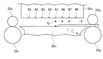
FIG. 1 is an explanatory diagram showing changes in the nozzles used on the
[0023]
In this printer, when the upper end of the printing paper is on the
[0024]
Further, the same sub-scan feed as in the upper end process is performed between the upper end process and the intermediate process, and the upper end transition process in which printing is performed using all nozzle groups is performed as in the intermediate process. Further, between the intermediate process and the lower end process, the same sub-scan feed as the lower end process is performed, and a lower end transition process is performed in which printing is performed using the nozzle groups Nh, Ni, and Nr. That is, the nozzle group Nf is not used in the lower end transition process. By performing these transition processes, the upper end process, the intermediate process, and the lower end process can be smoothly performed without performing the reverse feed of the sub-scan or the positioning feed that is a large feed. As a result, the printing quality is increased.
[0025]
B. First embodiment:
B1. Device configuration:
FIG. 2 is a block diagram illustrating a software configuration of the printing apparatus. In the
[0026]
When the
[0027]
The
[0028]
The color-corrected data has gradation values with a width of, for example, 256 gradations. The
In this embodiment, the
[0029]
Next, a schematic configuration of the
[0030]
A mechanism for reciprocating the
[0031]
The
[0032]
FIG. 4 is an explanatory diagram showing the arrangement of inkjet nozzles in the
[0033]
The nozzles in each nozzle array are classified into four subgroups in order from the upstream in the sub-scanning direction. This subgroup is a “partial dot forming element group” referred to in the claims. Hereinafter, the subgroups of each nozzle array are collectively referred to as nozzle groups Nf, Nh, Ni, and Nr in order from the upstream in the sub-scanning direction. The first nozzle group Nf on the most upstream side corresponds to the “first partial dot forming element group” in the claims, and the second nozzle group Nh has the “second portion” in the claims. It corresponds to “dot forming element group”. The third nozzle group Ni corresponds to the “third partial dot formation element group” in the claims, and the fourth nozzle group Nr has the “fourth partial dot formation element group” in the claims. It corresponds to. Here, the partial dot formation element groups of each nozzle array are collectively handled as nozzle groups Nf, Nh, Ni, and Nr, respectively. These nozzle groups are determined so as to correspond to the components such as the groove and the support of the
[0034]
FIG. 5 is a plan view showing the periphery of the
[0035]
The
[0036]
Further, the
[0037]
To explain in order from the upstream side in the sub-scanning direction, first, the upstream support portion 26sf is positioned in the main scanning direction at a position facing the first nozzle group Nf on the most upstream side among the nozzles on the
[0038]
Next, the internal configuration of the control circuit 40 (see FIG. 3) of the
[0039]
The
[0040]
In the first image printing mode to be described later, the upper end Pf of the printing paper P is printed on the
[0041]
The width W in the sub-scanning direction of the
[0042]
W = p × n + α
[0043]
Here, p is a single feed amount of the sub-scan feed in the upper and lower end processing. n is the number of sub-scan feeds performed in each of the upper end process and the lower end process. α is a sub-scan feed error assumed in each of the upper end process and the lower end process. The value of α in the
[0044]
B2. Relationship between image data and printing paper:
FIG. 6 is a plan view showing the relationship between the image data D and the printing paper P. In the first embodiment, the image data D is set beyond the upper end Pf of the printing paper P to the outside of the printing paper P. Similarly, on the lower end side, the image data D is set beyond the lower end Pr of the printing paper P to the outside of the printing paper P. Therefore, in the first embodiment, the relationship between the size of the image data D and the printing paper P and the arrangement of the image data D and the printing paper P during printing is as shown in FIG.
[0045]
In this specification, when the ends of the printing paper P are called in correspondence with the top and bottom of the image data recorded on the printing paper P, the words “upper end (part)” and “lower end (part)” are used. When the end of the printing paper P is called in correspondence with the traveling direction of the sub-scan feed of the printing paper P on 22, the words “front end (part)” and “rear end (part)” may be used. . In the present specification, in the printing paper P, “upper end (part)” corresponds to “front end (part)”, and “lower end (part)” corresponds to “rear end (part)”.
[0046]
B3. Sub-scan feed during printing:
(1) Upper end processing, upper end transition processing and intermediate processing:
FIG. 7 is an explanatory diagram showing how each raster is recorded by which nozzle in the vicinity of the upper end (front end) of the printing paper. Here, in order to simplify the description, description will be made using only one nozzle row. Each nozzle row has 11 nozzles with an interval of 3 rasters. However, the nozzles used in the upper end process are only three nozzles on the downstream side in the sub-scanning direction. In FIG. 7, only those three nozzles used for printing are shown, and the nozzles not used are not shown.
[0047]
In FIG. 7, one row of cells arranged vertically represents the
[0048]
As shown in FIG. 7, only the
[0049]
In the upper end process, the sub-scan feed of 3 dots is repeated 12 times. This three-dot sub-scan feed corresponds to the “first sub-scan mode” in the claims. Note that “dot” as a unit of the sub-scan feed amount means a pitch of one dot corresponding to the print resolution in the sub-scan direction, and this is equal to the raster pitch. Further, the area (see FIG. 7) on the printing paper P that is recorded during the twelve three-dot feeds corresponds to the “upper end” in the claims.
[0050]
When the sub-scan feed is performed as described above, each raster is recorded by one nozzle except for some rasters. For example, in FIG. 7, the seventh raster from the top is recorded by the # 1 nozzle. The eighth raster from the top is recorded by the # 2 nozzle.
[0051]
In FIG. 7, the nozzles do not pass through the second, third, and sixth rasters from the top in the main scanning during printing. Therefore, for these rasters, it is not possible to form dots on each pixel with a nozzle. Therefore, in the first image printing mode, the sixth raster from the top is not used for recording an image. That is, the rasters that can be used for recording an image in the first image printing mode are the seventh and subsequent rasters from the upstream end in the sub-scanning direction among the rasters in which the nozzles on the
[0052]
FIG. 8 is an explanatory diagram showing how each raster is recorded by which nozzle in the upper end process, the upper end transition process, and the intermediate process. After performing the upper end processing, the
[0053]
After the top transition process, the
[0054]
In FIG. 8, two nozzles pass through the 79th and 80th rasters from the top in the main scanning during printing. For such a raster in which two or more nozzles pass during printing, only one of the nozzles records a dot. Here, it is assumed that the nozzle that finally passes through the raster records dots. These rasters are preferably recorded by nozzles that pass over the raster after shifting to the upper edge transition process or intermediate process as much as possible. In the upper end transition process and the intermediate process, a larger number of nozzles are used than in the upper end process. For this reason, the characteristics of a small number of nozzles are not strongly reflected in the print result, and it can be expected that the print result will have high image quality.
[0055]
As a result of printing as described above, the areas from the seventh raster to the 51st raster counted from the uppermost raster on which the print head can record dots are
[0056]
In the first embodiment, an image is recorded without a margin up to the upper end of the printing paper. As described above, in the first embodiment, among the rasters in which the nozzles on the
[0057]
FIG. 9 is a side view showing the relationship between the
[0058]
The fourth nozzle group Nr previously shown in FIGS. 4 and 5 is the nozzles of # 1, # 2, and # 3 in FIG. A
[0059]
As described above, at the start of printing, the upper end Pf of the printing paper P is located at the 23rd raster position from the upstream end in the sub-scanning direction among the rasters on which the nozzles on the
[0060]
However, if the printing paper P is fed more than the original feeding amount for some reason, the upper end of the printing paper P is the 22nd raster from the top of the printable area or a raster higher than that. It may come to the position of. In the first embodiment, even in such a case, the nozzles of # 1, # 2, and # 3 eject ink droplets Ip to those rasters, so that an image is recorded on the upper end of the printing paper P. And no margins. That is, even when the printing paper P is fed more than the original feeding amount, as shown by the alternate long and short dash line in FIG. 9, if the extra feeding amount is 16 rasters or less, the printing paper P There will be no white space at the top edge.
[0061]
Conversely, it is also conceivable that the printing paper P is fed less than the original feed amount for some reason. In such a case, there is no printing paper at the position where the printing paper should originally be, and the ink droplet Ip will land on the structure below. However, as shown in FIGS. 7 and 8, in the first image printing mode, 29 rasters (up to the 51st raster in FIG. 8) from the assumed upper end position of the paper are # 1, # 2, and # 3. It is to be recorded by the nozzle. Downstream of these nozzles, a
[0062]
In the first embodiment, printing is performed using all nozzles in the intermediate processing. For this reason, high-speed printing can be performed in the intermediate processing.
[0063]
Furthermore, in the first embodiment, in the upper end transition process after the upper end process and before the intermediate process, the same sub-scan feed as in the upper end process is performed using all the nozzles as in the intermediate process. For this reason, the transition from the upper end process to the intermediate process can be smoothly performed without performing reverse feed in the sub-scanning. For this reason, the quality of the printing result is high.
[0064]
The effect described above is that when printing the upper end of the printing paper P, the fourth nozzle group Nr (fourth partial dot forming element group) when the upper end of the printing paper P is above the opening of the downstream groove 26r. ) Is ejected from at least a part of the ink to form dots on the printing paper P.
[0065]
As described above, the upper end processing by the fourth nozzle group Nr (
[0066]
(2) Lower end transition processing and lower end processing:
FIG. 10 to FIG. 12 are explanatory diagrams showing how each raster is recorded by which nozzle in the lower end transition process and the lower end process. In the first embodiment, as shown in FIG. 10, after all nozzles are used in the intermediate process and 11 dots are regularly fed,
[0067]
Then, as shown in FIGS. 11 and 12, after the lower end transition process, in the lower end process, only the # 7 to # 9 nozzles (second nozzle group Nh) are used, and the feed of 3 dots is performed 17 times. Go to form dots. This regular feeding by 3 dots corresponds to the “third sub-scanning mode” in the claims. The area on the printing paper P (see FIGS. 11 and 12) recorded during the 17-dot 3-dot feeding corresponds to the “lower end” in the claims. The “upper end”, “upper end transition portion”, “intermediate portion”, “lower end transition portion”, and “lower end portion” of the printing paper P are in order from the top in the surface portion of the printing paper P although they partially overlap each other. They are located side by side.
[0068]
When such feeding is performed, each raster along the main scanning direction is recorded by one nozzle, except for some rasters. In FIG. 10 to FIG. 12, numbers assigned sequentially from the bottom to the raster on which the nozzles on the
[0069]
In FIG. 12, the nozzles do not pass through the second, third, and sixth rasters from the bottom in the main scanning during printing. Accordingly, the printable area in the lower end portion of the printing paper is the seventh or more raster area from the bottom.
[0070]
In FIG. 10, two or more nozzles pass through the 80th and 81st rasters from the bottom in the main scan during printing. The same applies to the 59th and 63rd rasters from the bottom of FIG. For such a raster in which two or more nozzles pass in printing, the nozzle that first passes through the raster records dots. Such a raster is preferably recorded by a nozzle that passes over the raster in the intermediate process, the intermediate process, or the lower end transition process. In the intermediate process and the lower end transition process, a larger number of nozzles are used than in the lower end process. For this reason, the characteristics of a small number of nozzles are not strongly reflected in the print result, and it can be expected that the print result will have high image quality.
[0071]
When printing is performed as described above, as shown in FIGS. 11 and 12, the area up to the 58th raster from the lowest raster on which the print head can record dots is the
[0072]
In the first image printing mode, as in the case of the upper end, an image is recorded with no margin at the lower end. As described above, in the first embodiment, among the rasters in which the nozzles on the
[0073]
FIG. 13 is a plan view showing the relationship between the
[0074]
FIG. 14 is a side view showing the relationship between the
[0075]
However, if for some reason the printing paper P is fed less than the original feed amount, the # 7, # 8, # 9 nozzles are set beyond the lower end Pr of the printing paper P. Since the ink droplets Ip are ejected with respect to (the seventh to thirtyth rasters from the bottom in FIG. 12), an image can be recorded on the lower end Pr of the printing paper P, and a blank space is created. There is no. That is, when the short feed amount is equal to or less than 24 rasters, no margin is formed at the lower end of the printing paper P.
[0076]
The 28 rasters above the assumed lower end position of the paper (31st to 62nd rasters from the bottom in FIG. 11) are recorded by the # 7, # 8, and # 9 nozzles. Therefore, even when the printing paper P is fed more than the original feeding amount for some reason, the ejected ink droplet Ip can fall into the
[0077]
The effect described above is that when printing the lower end of the printing paper P, the second nozzle group Nh (second partial dot forming element group) when the lower end of the printing paper P is above the opening of the upstream groove 26f. ) Is ejected from at least a part of the ink to form dots on the printing paper P.
[0078]
In the first embodiment, printing is performed using all nozzles in the intermediate processing. For this reason, high-speed printing can be performed in the intermediate processing.
[0079]
Furthermore, in the first embodiment, only the nozzle groups Nh, Ni, and Nr (
[0080]
As described above, the lower end transition process by the nozzle groups Nh, Ni, Nr (
[0081]
C. Second embodiment:
FIG. 15 is a side view showing the relationship between the
[0082]
In the printing apparatus according to the second embodiment, the upstream support portion 26sf is provided at a position facing the
[0083]
The first nozzle group Nfa in the second embodiment corresponds to the “first partial dot forming element group” referred to in the claims, and the second nozzle group Nha refers to the “second part” in the claims. It corresponds to “dot forming element group”. The third nozzle group Nia corresponds to the “third partial dot formation element group” in the claims, and the fourth nozzle group Nra has the “fourth partial dot formation element group” in the claims. It corresponds to. Here, the partial dot formation element groups of each nozzle array are collectively handled as nozzle groups Nfa, Nha, Nia, and Nra, respectively.
[0084]
(1) Upper end processing, upper end transition processing and intermediate processing:
FIG. 16 is an explanatory diagram showing how each raster is recorded by which nozzle in the upper end processing of the second embodiment. As shown in FIG. 16, in the upper end process of the second embodiment, the fourth nozzle group Nra (
[0085]
After top edge processing, use all
[0086]
FIG. 17 is an explanatory diagram showing how each raster is recorded by which nozzle in the intermediate processing of the second embodiment. After the upper end shifting process, the process shifts to an intermediate process as shown in FIG. 17 and using all
[0087]
As a result of feeding as described above, each raster is recorded by two nozzles by two main scans. Note that, as shown in FIG. 16, with respect to a raster through which three or more nozzles pass, such as the 25th and 28th rasters from the top, only the two nozzles that finally pass through the raster record dots. And
[0088]
As shown in FIG. 16, in the second embodiment, among the rasters on which the nozzles on the
[0089]
In the second embodiment, printing is performed using all nozzles in the intermediate process. Therefore, printing can be performed at a higher speed than when some of the nozzles are not used. In the second embodiment, all nozzles are used between the upper end process and the intermediate process as in the intermediate process, and the same feed as the upper end process (2 dots, 3 dots, 2 dots, 2 dots, 1 dot, Upper end transition processing is performed to perform (2 dot feed). For this reason, reverse transfer is not required when shifting from the upper end process to the intermediate process, and printing can be performed smoothly. For this reason, the quality of the printing result is high.
[0090]
(2) Lower end transition processing and lower end processing:
FIG. 18 is an explanatory diagram showing how each raster is recorded by which nozzle in the intermediate process, the lower end transition process, and the lower end process of the second embodiment. The table shown in the upper part of the figure shows each sub-scan feed amount. In the second embodiment, as shown in FIG. 18, in the intermediate processing, after 20 dots, 27 dots, 22 dots, 28 dots, 21 dots, and 26 dots are irregularly fed using all the nozzles, the lower end transition is performed. In the process,
[0091]
In the second embodiment described above, the first nozzle group Nfa (nozzles # 35 to # 48) positioned upstream from the second nozzle group Nha is used between the intermediate process and the lower end process. In addition, a lower end transition process is performed in which the same feed as the lower end process (an irregular feed of 2 dots, 3 dots, 2 dots, 2 dots, 1 dot, 2 dots) is performed. For this reason, when shifting from the intermediate process to the lower end process, no reverse feed is required, and printing can be performed smoothly. For this reason, the quality of the printing result is high.
[0092]
Further, in the second embodiment, the irregular feeding is performed through the upper end process, the upper end shift process, the intermediate process, the lower end shift process, and the lower end process. For this reason, the quality of the printing result is higher than that in the case of performing regular feeding. In addition, since overlap printing is performed, the quality of the print result is higher than when overlap printing is not performed.
[0093]
D. Third embodiment:
(1) Overview of the third embodiment:
FIG. 19 is an explanatory diagram showing changes in nozzles used on the
[0094]
The printing of the third embodiment is different from the printing of the first embodiment in that nozzles #A and #B are used in the intermediate processing and the lower end transition processing. The other points are the same as the printing in the first embodiment.
[0095]
In the printer of the third embodiment, when the upper end of the printing paper is on the
[0096]
Further, during the upper end process and the intermediate process, the same sub-scan feed as in the upper end process is performed, and the upper end transition process for performing printing using Nf, Nh, Ni, and Nr is performed. In the upper end transition process, the nozzle group Nt is not used. Also, between the intermediate process and the lower end process, the same sub-scan feed as the lower end process is performed, and a lower end transition process for performing printing using the nozzle groups Nh, Ni, Nr, and Nt is performed. In the lower end transition process, the nozzle group Nf is not used.
[0097]
(2) Upper end processing, upper end transition processing and intermediate processing:
FIG. 20 is an explanatory diagram showing how each raster is recorded by which nozzle in the vicinity of the upper end (front end) of the printing paper. FIG. 21 is an explanatory diagram showing how each raster is recorded by which nozzle in the upper end process, the upper end shift process, and the intermediate process. In the third embodiment, the nozzles used in the upper end processing are only the
[0098]
In the upper end process, as in the first embodiment, the sub-scan feed by 3 dots is repeated 12 times. This three-dot sub-scan feed corresponds to the “first sub-scan mode” in the claims. An area on the printing paper P (see FIG. 20) recorded during the 12-dot 3-dot feeding corresponds to the “upper end” in the claims. In the third embodiment, the printable area is the 15th and subsequent raster areas from the top, and the 14th raster area is the unprintable area.
[0099]
As shown in FIG. 20, in the third embodiment, the assumed upper end position of the printing paper is the position of the 30th raster. On the other hand, in the third embodiment, the area from the 15th raster to the 50th raster (not shown in FIG. 20) from the top is recorded in the upper end process using
[0100]
The printer according to the third embodiment performs the upper end transition process using
[0101]
After the upper edge transition process, the process proceeds to an intermediate process in which all nozzles #A to # 11 are used to perform regular feeding of 13 dots to record dots. This 13-dot sub-scan feed corresponds to the “second sub-scan mode” in the claims. An area on the printing paper P (see FIG. 21) recorded during the 13-dot sub-scan feed corresponds to an “intermediate portion” in the claims. By performing such upper end transition processing, it is possible to smoothly transition from the upper end processing to the intermediate processing. Further, since printing is performed using all nozzles in the intermediate processing, printing can be performed at high speed.
[0102]
(3) Lower end transition processing and lower end processing:
FIG. 22 and FIG. 23 are explanatory diagrams showing how each raster is recorded by which nozzle in the lower end transition process and the lower end process. In the third embodiment, in the intermediate process, all nozzles are used, and the regular feeding of 13 dots is repeated. Thereafter, in the lower end transition process, the #A to # 9 nozzles (nozzle groups Nt, Nr, Ni, and Nh) are used to form dots by performing three-dot feeding five times (see FIG. 19). In the lower-end transition process, the first nozzle group Nf (
[0103]
As shown in FIG. 23, after the lower end transition process, in the lower end process, only the # 7 to # 9 nozzles (second nozzle group Nh) are used, and dots are formed by performing 13-
[0104]
As shown in FIG. 23, in the third embodiment, the non-printable area at the lower end portion of the printing paper is from the lowest raster on which the print head can record dots to the 14th raster. The printable area is an area of the 15th and higher rasters from the lowest raster.
[0105]
As shown in FIG. 23, in the third embodiment, the assumed lower end position of the printing paper is the position of the 31st raster from the lowest raster on which the print head can record dots. In the third embodiment, the area from the 15th raster to the 47th raster from the bottom is recorded in the lower end process using
[0106]
(3) Influence of the performance of each nozzle on printing results:
FIG. 24 is a graph showing the difference in performance of each nozzle arranged in the sub-scanning direction. FIG. 24A is a graph showing the ink droplet ejection speed of each nozzle arranged in the sub-scanning direction. Here, in order to show the relationship between the position of the nozzles in the nozzle row and the performance in an easy-to-understand manner, a graph for a nozzle row having 48 nozzles in one row is shown. As shown by the solid line and the alternate long and short dash line in FIG. 24A, the variation of the ink droplet ejection speed Vk from the design value Vk0 tends to be larger at the end nozzle. That is, for the nozzles near the
[0107]
In addition to variations in ink droplet ejection speed, variations in the direction in which ink droplets are ejected from each nozzle may increase as the nozzles at the end in the sub-scanning direction increase. As described above, for various reasons, the displacement of the dot formation position on the printing paper may increase as the nozzles at the end in the sub-scanning direction are increased.
[0108]
FIG. 24B is a graph showing the weight of ink droplets ejected from each nozzle arranged in the sub-scanning direction. FIG. 24B also shows a graph for a nozzle row having 48 nozzles in one row in order to easily understand the relationship between the position of the nozzles in the nozzle row and the performance. Regarding the ink drop weight Iw, the variation from the design value Iw0 is larger as the nozzle is closer to the end. Regarding the tendency of the variation, as shown by a solid line in FIG. 24B, the weight of the ink droplet may increase as the nozzle is at the end, and as indicated by a one-point difference line, the ink droplet as the end nozzle is increased. In some cases, the weight of the resin becomes smaller. In addition, for one end, the weight of the ink droplet may be smaller for the end nozzle, and for the other end, the weight may be greater for the end nozzle. If the weight of the ink droplets varies, the size of the dots on the printing paper varies. Therefore, the use of the nozzles near the edge in printing may reduce the quality of the printing result.
[0109]
When performing the upper end processing and the lower end processing using the printer having such a tendency, it is preferable not to use an end nozzle. When using only the nozzles located at the end in the top edge processing and bottom edge processing where printing is performed with only some of the nozzles, the quality of the printed results is particularly poor compared to intermediate processing using all nozzles. Because it is considered to be.
[0110]
Further, when printing at the edge, the printing paper may be instructed by only one of the upstream
[0111]
In the third embodiment, the nozzles #A and #B located at the downstream end are not used in the upper end process. The
[0112]
It should be noted that the deviation of the dot formation position of each nozzle on the printing paper and the deviation of the ink droplet ejection speed do not necessarily coincide with the curves of the graphs as shown in FIGS. That is, if the average positional deviation of the dot formation positions of the nozzles of the nozzle group Nr on the printing medium is smaller than the average positional deviation of the dot formation positions of the nozzle group Nt, the upper end process as in the third embodiment is performed. The quality of the printing result can be further increased. If the average positional deviation of the dot formation positions of the nozzles of the nozzle group Nh on the printing medium is smaller than the average positional deviation of the dot formation positions of the nozzle group Nf, the lower end process as in the third embodiment is performed. The quality of the printing result can be further increased.
[0113]
Similarly, if the average displacement amount of the ink droplet ejection speed is smaller than the nozzles of the nozzle group Nt, the average position of the dot formation positions on the print medium in the upper end process is the result. High quality printing can be performed using a nozzle with a small amount of misalignment. If the average displacement amount of the ink droplet ejection speed is smaller than that of the nozzle group Nf of the nozzle group Nh, as a result, the average positional deviation of the dot formation position on the print medium in the lower end processing is obtained. High quality printing can be performed using a small amount of nozzle. Such an effect is also exhibited in the first and second embodiments in which the nozzle group Nh is used without using the nozzle group Nf positioned at the uppermost stream in the lower end process.
[0114]
(4) Determination of the amount of deviation of the dot formation position:
FIG. 25 is an explanatory diagram showing the principle of the diaphragm inspection method. In FIG. 25, a
[0115]
The deviation of the dot formation position can be calculated as follows. When the distance from the nozzle n to the
[0116]
Vk = Ls / ti (1)
[0117]
FIG. 26 is an explanatory diagram showing the relationship between the position of the nozzle that ejects ink droplets and the landing position of the ink droplets. The nozzles n on the
[0118]
tp = Lp / Vk (2)
[0119]
Further, the difference Dm in the main scanning direction between the position of the nozzle in the main scanning direction when the ink droplet is ejected and the landing position of the ink droplet is obtained from the main scanning speed Vs of the
[0120]
Dm = Vs × tp (3)
[0121]
One reference nozzle is determined from the nozzles of the
[0122]
Dd (i) = Dm (i) −Dm0 (4)
[0123]
The average deviation amount of the dot formation position of the nozzle group can be obtained by averaging this Dd for each nozzle group. Here, one reference nozzle is determined, and the difference Dm between the ink droplet ejection position and the ink droplet landing position of that nozzle is defined as the reference value Dm0. However, Dm0 can also be determined by other methods. For example, the average value of Dm (i) of all the nozzles or a predetermined part of the nozzles may be Dm0.
[0124]
Here, the amount of deviation at the dot formation position is calculated from the flying time of the ink droplets, but can also be determined by other methods. For example, an ink droplet ejection signal is sent to a plurality of nozzles at the same timing. Then, dots may be actually formed on the printing paper, and the dot formation position may be measured. For example, one reference nozzle is determined from the nozzles of the
[0125]
After measuring the deviation from the dot position in the main scanning direction and the sub-scanning direction, when calculating the average dot formation position deviation of each nozzle group and evaluating the magnitude, the estimated dot position and the actual position The distance Dc between can be used as a reference. When the dot formation position deviation amount in the main scanning direction is Dd and the dot formation position deviation amount in the sub scanning direction is De, the distance Dc between the assumed dot position and the actual position can be determined by the following equation.
[0126]
Dc = (Dd 2 + De 2 ) 1/2 ... (5)
[0127]
In such an embodiment, not only the dot formation position deviation in the main scanning direction but also the dot formation position deviation in the sub-scanning direction can be considered. However, even when the amount of deviation is evaluated by actually forming dots on the printer and measuring the dot formation position, only one of the deviations in the main scanning direction or the sub-scanning direction can be used as a reference.
[0128]
E. Variations:
The present invention is not limited to the above-described examples and embodiments, and can be implemented in various modes without departing from the gist thereof. For example, the following modifications are possible.
[0129]
E1. Modification 1:
In the first embodiment and the third embodiment, regular feeding is performed in units of 3 dots in the first sub-scanning mode, and in the first sub-scanning mode of the second embodiment, 2 dots, 3 dots, 2 dots, 2 dots An irregular feed of 1 dot and 2 dots was performed. However, the feed of the upper end process and the lower end process is not limited to this, and other regular feeds and irregular feeds can be used according to the number of nozzles in the nozzle row and the nozzle pitch. That is, it is sufficient if the maximum sub-scan feed amount is smaller than the maximum sub-scan feed amount in the intermediate process. However, the smaller the feed amount of the sub-scan feed of the upper end process, the more the upper end of the printing paper can be recorded with the nozzle on the downstream side in the sub-scan direction. Therefore, the downstream groove can be made narrower, and the upper surface of the platen that supports the printing paper can be widened. Similarly, the lower the sub-scan feed amount of the lower end process, the higher the upper-side nozzle can record the upper end of the printing paper. Therefore, the upstream groove can be made narrower, and the upper surface of the platen center that supports the printing paper can be widened.
[0130]
In the above embodiment, the feed in the first sub-scan mode and the feed in the third sub-scan mode are the same, but they do not necessarily have to be the same. For example, in the printer of the second embodiment, the feed in the first sub-scan mode is an irregular feed of 2 dots, 3 dots, 2 dots, 2 dots, 1 dot, 2 dots, and the feed in the third sub-scan mode. May be an irregular feed of 2 dots, 1 dot, 2 dots, 3 dots, 2 dots, 2 dots. And it is not always necessary to perform regular feeding through printing from the upper end process to the lower end process as in the first and third embodiments, and printing from the upper end process to the lower end process as in the second embodiment. There is no need to send an irregular feed through. The feeding in the first sub-scanning mode and the feeding in the third sub-scanning mode may be regular feeding, and the second sub-scanning mode may be irregular feeding. That is, it is only necessary that the maximum sub-scan feed amount of the feed in the first sub-scan mode and the third sub-scan mode is smaller than the maximum sub-scan feed amount in the second sub-scan mode. .
[0131]
E2. Modification 2:
The present invention can be applied not only to color printing but also to monochrome printing. The present invention can be applied not only to an ink jet printer but also to a dot recording apparatus that performs recording on the surface of a recording medium using a recording head having a plurality of dot forming element arrays. Here, “dot forming element” means a component for forming dots, such as an ink nozzle in an ink jet printer.
[0132]
E3. Modification 3:
In the above embodiment, a part of the configuration realized by hardware may be replaced with software, and conversely, a part of the configuration realized by software may be replaced by hardware. For example, the
[0133]
A computer program for realizing such a function is provided in a form recorded on a computer-readable recording medium such as a floppy disk or a CD-ROM. The
[0134]
In this specification, the
[0135]
In the present invention, the “computer-readable recording medium” is not limited to a portable recording medium such as a flexible disk or a CD-ROM, but an internal storage device in a computer such as various RAMs and ROMs, An external storage device fixed to a computer such as a hard disk is also included.
[Brief description of the drawings]
FIG. 1 is an explanatory diagram showing changes in nozzles used on a print head of an ink jet printer according to an embodiment of the present invention.
FIG. 2 is a block diagram illustrating a software configuration of the printing apparatus.
FIG. 3 is an explanatory diagram illustrating a schematic configuration of a printer.
FIG. 4 is an explanatory diagram showing an example of the arrangement of inkjet nozzles in the print head.
5 is a plan view showing the periphery of a
6 is a plan view showing a relationship between image data D and printing paper P. FIG.
FIG. 7 is an explanatory diagram showing how each raster is recorded by which nozzle in the vicinity of the upper end (tip) of the printing paper.
FIG. 8 is an explanatory diagram showing how each raster is recorded by which nozzle in the upper end process, the upper end shift process, and the intermediate process.
FIG. 9 is a side view showing the relationship between the
FIG. 10 is an explanatory diagram showing how each raster is recorded by which nozzle in an intermediate process and a lower edge transition process.
FIG. 11 is an explanatory diagram showing how each raster is recorded by which nozzle in the intermediate process, the lower end transition process, and the lower end process.
FIG. 12 is an explanatory diagram showing how each raster is recorded by which nozzle in the lower end processing.
13 is a plan view showing the relationship between the
14 is a side view showing the relationship between the
FIG. 15 is a side view showing a relationship between a
FIG. 16 is an explanatory diagram showing how each raster is recorded by which nozzle in the upper end process of the second embodiment.
FIG. 17 is an explanatory diagram showing how each raster is recorded by which nozzle in the intermediate processing of the second embodiment.
FIG. 18 is an explanatory diagram illustrating how each raster is recorded by which nozzle in the intermediate process, the lower end transition process, and the lower end process of the second embodiment.
FIG. 19 is an explanatory diagram showing changes in nozzles used on the print head in the third embodiment.
FIG. 20 is an explanatory diagram showing how each raster is recorded by which nozzle in the vicinity of the upper end (tip) of the printing paper.
FIG. 21 is an explanatory diagram illustrating how each raster is recorded by which nozzle in the upper end process, the upper end shift process, and the intermediate process.
FIG. 22 is an explanatory diagram showing how each raster is recorded by which nozzle in the lower end transition process and the lower end process.
FIG. 23 is an explanatory diagram illustrating how each raster is recorded by which nozzle in the lower end transition process and the lower end process.
FIG. 24 is a graph showing a difference in performance of each nozzle arranged in the sub-scanning direction.
FIG. 25 is an explanatory diagram showing the principle of a diaphragm inspection method.
FIG. 26 is an explanatory diagram showing the relationship between the position of a nozzle that ejects an ink droplet and the landing position of the ink droplet.
FIG. 27 is a side view showing the periphery of a print head of a conventional printer.
[Explanation of symbols]
12 ... Scanner
13 ... Mouse
21 ... CRT
22 ... Printer
23 ... Paper feed motor
24 ... Carriage motor
25a, 25b ... upstream paper feed roller
25c, 25d ... downstream paper feed roller
25p, 25q ... upstream paper feed roller
25r, 25s ... downstream paper feed roller
26, 26o ... Platen
26c, 26ca ... center support part
26f, 26fa ... Upstream groove
26r, 26ra ... Downstream groove
26sf: Upstream support section
26 sr ... downstream support section
27f, 27r ... absorbent member
28, 28a, 28o ... print head
31 ... Carriage
32 ... Control panel
34 ... Sliding shaft
36 ... Drive belt
38 ... pulley
39 ... Position detection sensor
40 ... Control circuit
41 ... CPU
41p ... Upper end printing section
41q ... upper end transition printing section
41r ... intermediate printing section
41s ... Bottom transition printing section
41t ... Bottom end printing section
42 ... PROM
43 ... RAM
44 ... Drive buffer
45 ... PC interface
52 ... Inspection section
52a ... Diaphragm
52b ... Microphone
61-66 ... Ink discharge head
71 ... Black ink cartridge
72. Color ink cartridge
80: Ink passage
90 ... Host computer
91 ... Video driver
95 ... Application program
96 ... Printer driver
97 ... Resolution conversion module
98 ... Color correction module
99 ... Halftone module
100 ... Rasterizer
A ... Arrow
D ... Image data
DT ... Dot formation pattern table
Dm: Difference between the position of the nozzle when ejecting the ink droplet and the landing position of the ink droplet
Ip ... ink drop
Iw ... Ink drop weight
LUT ... Color correction table
Nf, Nfa ... first nozzle group
Nh, Nha ... second nozzle group
Ni, Nia ... third nozzle group
Nr, Nra ... Fourth nozzle group
ORG ... Original color image data
P: Printing paper
PD ... Print data
PE ... piezo element
Pf… Upper end
Pr ... Bottom
R26: Range in which the
Vk: Ink droplet ejection speed (flying speed)
Vs ... Main scanning speed
k ... Nozzle pitch
n ... Nozzle
Claims (26)
前記ドット記録ヘッドを前記印刷媒体に対して動かして主走査を行う主走査部と、
前記主走査の最中に前記複数のドット形成要素のうちの少なくとも一部を駆動してドットの形成を行わせるヘッド駆動部と、
前記主走査の行路の少なくとも一部において前記複数のドット形成要素と向かい合うように、前記主走査の方向に延長して設けられ、前記印刷媒体を前記ドット記録ヘッドと向かい合うように支持するプラテンと、
前記主走査の合間に前記印刷媒体を前記主走査の方向と交わる方向に搬送して副走査を行う副走査部と、
前記各部を制御するための制御部と、を備え、
前記プラテンは、
前記複数のドット形成要素の一部のドット形成要素からなる第1の部分ドット形成要素群と向かい合う位置に前記主走査の方向に延長して設けられ、前記印刷媒体を支える第1の支持部と、
前記複数のドット形成要素のうち前記第1の部分ドット形成要素群よりも前記印刷媒体の前記搬送の方向の下流側に設けられる第2の部分ドット形成要素群と向かい合う位置に、前記主走査の方向に延長して設けられる第1の溝部と、
前記複数のドット形成要素のうち前記第2の部分ドット形成要素群よりも前記印刷媒体の前記搬送の方向の下流側に設けられる第3の部分ドット形成要素群と向かい合う位置に前記主走査の方向に延長して設けられ、前記印刷媒体を支える第2の支持部と、
前記複数のドット形成要素のうち前記第3の部分ドット形成要素群よりも前記印刷媒体の前記搬送の方向の下流側に設けられる第4の部分ドット形成要素群と向かい合う位置に、前記主走査の方向に延長して設けられる第2の溝部と、を有しており、
前記印刷媒体において、前記搬送の際に先端となる方向を上とし、後端となる方向を下とし、前記印刷媒体の表面部を、上から順に、上端を含む上端部、上端移行部、中間部、下端移行部、下端を含む下端部、と区分したときに、
前記制御部は、
前記第1ないし第3の部分ドット形成要素群を使用せずに、前記第4の部分ドット形成要素群を使用して、第1の副走査モードで、前記上端部にドットを形成する上端印刷部と、
前記第1ないし第4の部分ドット形成要素群を使用して、前記第1の副走査モードで、前記上端移行部にドットを形成する上端移行印刷部と、
前記第1ないし第4の部分ドット形成要素群を使用して、前記副走査の最大の送り量が前記第1の副走査モードの副走査の最大の送り量よりも大きい第2の副走査モードで、前記中間部にドットを形成する中間印刷部と、を備えるドット記録装置。A dot recording apparatus that records dots on the surface of a print medium using a dot recording head provided with a dot forming element group composed of a plurality of dot forming elements that eject ink droplets,
A main scanning unit that performs main scanning by moving the dot recording head with respect to the print medium;
A head driving unit that drives at least some of the plurality of dot forming elements during the main scanning to form dots; and
A platen extending in the main scanning direction so as to face the plurality of dot forming elements in at least a part of the main scanning path, and supporting the printing medium so as to face the dot recording head;
A sub-scanning unit that performs sub-scanning by transporting the print medium in a direction crossing the main scanning direction between the main scannings;
A control unit for controlling the respective units,
The platen is
A first support portion that extends in the main scanning direction at a position facing a first partial dot formation element group including a part of the plurality of dot formation elements, and supports the print medium; ,
Among the plurality of dot forming elements, the main scanning is performed at a position facing a second partial dot forming element group provided downstream of the first partial dot forming element group in the transport direction of the print medium . A first groove provided extending in the direction;
The direction of the main scanning at a position facing a third partial dot formation element group provided downstream of the second partial dot formation element group in the transport direction of the print medium from the plurality of dot formation elements A second support portion provided to extend to support the print medium;
Among the plurality of dot forming elements, the main scanning is performed at a position facing a fourth partial dot forming element group provided downstream of the third partial dot forming element group in the transport direction of the print medium . A second groove provided extending in the direction,
In the print medium, the direction at the leading end in the conveyance is up, the direction at the rear end is down, and the surface portion of the print medium in order from the top is an upper end including the upper end, an upper end transition portion, an intermediate Part, lower end transition part, lower end part including the lower end,
The controller is
Upper end printing for forming dots on the upper end portion in the first sub-scanning mode using the fourth partial dot formation element group without using the first to third partial dot formation element groups. And
Using the first to fourth partial dot forming element groups, in the first sub-scanning mode, an upper end transition printing unit that forms dots on the upper end transition unit; and
Using the first to fourth partial dot forming element groups, a second sub-scanning mode in which the maximum sub-scan feed amount is larger than the maximum sub-scan feed amount in the first sub-scan mode. An intermediate printing unit that forms dots in the intermediate unit.
前記上端印刷部は、前記印刷媒体が前記プラテンに支持され、かつ、前記印刷媒体の上端が前記第2の溝部の開口上にあるときに、前記上端部にドットを形成する、ドット記録装置。The dot recording apparatus according to claim 1,
The upper end printing unit is a dot recording apparatus that forms dots on the upper end when the print medium is supported by the platen and the upper end of the print medium is over the opening of the second groove.
前記制御部は、さらに、
前記第1の部分ドット形成要素群を使用せずに、前記第2ないし第4の部分ドット形成要素群を使用して、前記副走査の最大の送り量が前記第2の副走査モードの副走査の最大の送り量よりも小さい第3の副走査モードで、前記下端移行部にドットを形成する下端移行印刷部と、
前記第1、第3および第4の部分ドット形成要素群を使用せずに、前記第2の部分ドット形成要素群を使用して、前記第3の副走査モードで、前記下端部にドットを形成する下端印刷部と、を備えるドット記録装置。The dot recording apparatus according to claim 1,
The control unit further includes:
Using the second to fourth partial dot formation element groups without using the first partial dot formation element group, the maximum feed amount of the sub-scan is the sub-scan mode of the second sub-scan mode. A lower-end transition printing unit that forms dots in the lower-end transition unit in a third sub-scanning mode smaller than the maximum scanning feed amount;
Instead of using the first, third and fourth partial dot formation element groups, the second partial dot formation element group is used, and in the third sub-scan mode, dots are formed at the lower end portion. A dot recording apparatus comprising: a lower end printing unit to be formed.
前記第2の部分ドット形成要素群のノズルは、前記第1の部分ドット形成要素群のノズルよりも、前記印刷媒体上のドット形成位置の平均ズレ量が小さい、ドット記録装置。The dot recording apparatus according to claim 3,
The nozzle of the second partial dot formation element group is a dot recording apparatus in which an average deviation amount of dot formation positions on the print medium is smaller than that of the nozzle of the first partial dot formation element group.
前記下端印刷部は、前記印刷媒体が前記プラテンに支持され、かつ、前記印刷媒体の下端が前記第1の溝部の開口上にあるときに、前記下端部にドットを形成する、ドット記録装置。The dot recording apparatus according to claim 3,
The lower end printing unit is a dot recording apparatus that forms dots at the lower end when the print medium is supported by the platen and the lower end of the print medium is above the opening of the first groove.
前記ドット記録ヘッドを前記印刷媒体に対して動かして主走査を行う主走査部と、
前記主走査の最中に前記複数のドット形成要素のうちの少なくとも一部を駆動してドットの形成を行わせるヘッド駆動部と、
前記主走査の行路の少なくとも一部において前記複数のドット形成要素と向かい合うように、前記主走査の方向に延長して設けられ、前記印刷媒体を前記ドット記録ヘッドと向かい合うように支持するプラテンと、
前記主走査の合間に前記印刷媒体を前記主走査の方向と交わる方向に搬送して副走査を行う副走査部と、
前記各部を制御するための制御部と、を備え、
前記プラテンは、
前記複数のドット形成要素の一部のドット形成要素からなる第1の部分ドット形成要素群と向かい合う位置に前記主走査の方向に延長して設けられ、前記印刷媒体を支える第1の支持部と、
前記複数のドット形成要素のうち前記第1の部分ドット形成要素群よりも前記印刷媒体の前記搬送の方向の下流側に設けられる第2の部分ドット形成要素群と向かい合う位置に、前記主走査の方向に延長して設けられる第1の溝部と、
前記複数のドット形成要素のうち前記第2の部分ドット形成要素群よりも前記印刷媒体の前記搬送の方向の下流側に設けられる第3の部分ドット形成要素群と向かい合う位置に前記主走査の方向に延長して設けられ、前記印刷媒体を支える第2の支持部と、
前記複数のドット形成要素のうち前記第3の部分ドット形成要素群よりも前記印刷媒体の前記搬送の方向の下流側に設けられる第4の部分ドット形成要素群と向かい合う位置に、前記主走査の方向に延長して設けられる第2の溝部と、
前記複数のドット形成要素のうち前記第4の部分ドット形成要素群よりも前記印刷媒体の前記搬送の方向の下流側に設けられる第5の部分ドット形成要素群と向かい合う位置に前記主走査の方向に延長して設けられ、前記印刷媒体を支える第3の支持部と、を有しており、
前記印刷媒体において、前記搬送の際に先端となる方向を上とし、後端となる方向を下とし、前記印刷媒体の表面部を、上から順に、上端を含む上端部、上端移行部、中間部、下端移行部、下端を含む下端部、と区分したときに、
前記制御部は、
前記第1、第2、第3および第5の部分ドット形成要素群を使用せずに、前記第4の部分ドット形成要素群を使用して、第1の副走査モードで、前記上端部にドットを形成する上端印刷部と、
前記第1ないし第4の部分ドット形成要素群を使用して、前記第1の副走査モードで、前記上端移行部にドットを形成する上端移行印刷部と、
前記第1ないし第5の部分ドット形成要素群を使用して、前記副走査の最大の送り量が前記第1の副走査モードの副走査の最大の送り量よりも大きい第2の副走査モードで、前記中間部にドットを形成する中間印刷部と、を備えるドット記録装置。A dot recording apparatus that records dots on the surface of a print medium using a dot recording head provided with a dot forming element group composed of a plurality of dot forming elements that eject ink droplets,
A main scanning unit that performs main scanning by moving the dot recording head with respect to the print medium;
A head driving unit that drives at least some of the plurality of dot forming elements during the main scanning to form dots; and
A platen extending in the main scanning direction so as to face the plurality of dot forming elements in at least a part of the main scanning path, and supporting the printing medium so as to face the dot recording head;
A sub-scanning unit that performs sub-scanning by transporting the print medium in a direction crossing the main scanning direction between the main scannings;
A control unit for controlling the respective units,
The platen is
A first support portion that extends in the main scanning direction at a position facing a first partial dot formation element group including a part of the plurality of dot formation elements, and supports the print medium; ,
Among the plurality of dot forming elements, the main scanning is performed at a position facing a second partial dot forming element group provided downstream of the first partial dot forming element group in the transport direction of the print medium . A first groove provided extending in the direction;
The direction of the main scanning at a position facing a third partial dot formation element group provided downstream of the second partial dot formation element group in the transport direction of the print medium from the plurality of dot formation elements A second support portion provided to extend to support the print medium;
Among the plurality of dot forming elements, the main scanning is arranged at a position facing a fourth partial dot forming element group provided downstream of the third partial dot forming element group in the transport direction of the print medium . A second groove provided extending in the direction;
The direction of the main scanning at a position facing a fifth partial dot formation element group provided downstream of the fourth partial dot formation element group in the transport direction of the print medium from the plurality of dot formation elements And a third support part that supports the print medium,
In the print medium, the direction at the leading end in the conveyance is up, the direction at the rear end is down, and the surface portion of the print medium in order from the top is an upper end including the upper end, an upper end transition portion, an intermediate Part, lower end transition part, lower end part including the lower end,
The controller is
Without using the first, second, third and fifth partial dot forming element groups, the fourth partial dot forming element group is used and the upper end portion is applied to the upper end portion in the first sub-scanning mode. A top-end printing section for forming dots;
Using the first to fourth partial dot forming element groups, in the first sub-scanning mode, an upper end transition printing unit that forms dots on the upper end transition unit; and
Using the first to fifth partial dot forming element groups, a second sub-scanning mode in which the maximum sub-scan feed amount is larger than the maximum sub-scan feed amount in the first sub-scan mode. An intermediate printing unit that forms dots in the intermediate unit.
前記第4の部分ドット形成要素群のノズルは、前記第5の部分ドット形成要素群のノズルよりも、前記印刷媒体上のドット形成位置の平均ズレ量が小さい、ドット記録装置。The dot recording apparatus according to claim 6, wherein:
The nozzle of the fourth partial dot formation element group is a dot recording apparatus in which the average deviation amount of the dot formation position on the print medium is smaller than the nozzle of the fifth partial dot formation element group.
前記上端印刷部は、前記印刷媒体が前記プラテンに支持され、かつ、前記印刷媒体の上端が前記第2の溝部の開口上にあるときに、前記上端部にドットを形成する、ドット記録装置。The dot recording apparatus according to claim 6, wherein:
The upper end printing unit is a dot recording apparatus that forms dots on the upper end when the print medium is supported by the platen and the upper end of the print medium is over the opening of the second groove.
前記制御部は、さらに、
前記第1の部分ドット形成要素群を使用せずに、前記第2ないし第5の部分ドット形成要素群を使用して、前記副走査の最大の送り量が前記第2の副走査モードの副走査の最大の送り量よりも小さい第3の副走査モードで、前記下端移行部にドットを形成する下端移行印刷部と、
前記第1、第3、第4および第5の部分ドット形成要素群を使用せずに、前記第2の部分ドット形成要素群を使用して、前記第3の副走査モードで、前記下端部にドットを形成する下端印刷部と、を備えるドット記録装置。The dot recording apparatus according to claim 6, wherein:
The control unit further includes:
By using the second to fifth partial dot forming element groups without using the first partial dot forming element group, the maximum feed amount of the sub scanning is the sub amount in the second sub scanning mode. A lower-end transition printing unit that forms dots in the lower-end transition unit in a third sub-scanning mode smaller than the maximum scanning feed amount;
Using the second partial dot formation element group without using the first, third, fourth, and fifth partial dot formation element groups, the lower end portion in the third sub-scanning mode A dot recording device comprising: a lower end printing unit that forms dots on the lower end printing unit.
前記第2の部分ドット形成要素群のノズルは、前記第1の部分ドット形成要素群のノズルよりも、前記印刷媒体上のドット形成位置の平均ズレ量が小さい、ドット記録装置。The dot recording apparatus according to claim 9, wherein
The nozzle of the second partial dot formation element group is a dot recording apparatus in which an average deviation amount of dot formation positions on the print medium is smaller than that of the nozzle of the first partial dot formation element group.
前記下端印刷部は、前記印刷媒体が前記プラテンに支持され、かつ、前記印刷媒体の下端が前記第1の溝部の開口上にあるときに、前記下端部にドットを形成する、ドット記録装置。The dot recording apparatus according to claim 9, wherein
The lower end printing unit is a dot recording apparatus that forms dots at the lower end when the print medium is supported by the platen and the lower end of the print medium is above the opening of the first groove.
前記プラテンは、
前記複数のドット形成要素の一部のドット形成要素からなる第1の部分ドット形成要素群と向かい合う位置に前記主走査の方向に延長して設けられ、前記印刷媒体を支える第1の支持部と、
前記複数のドット形成要素のうち前記第1の部分ドット形成要素群よりも前記印刷媒体の前記搬送の方向の下流側に設けられる第2の部分ドット形成要素群と向かい合う位置に、前記主走査の方向に延長して設けられる第1の溝部と、
前記複数のドット形成要素のうち前記第2の部分ドット形成要素群よりも前記印刷媒体の前記搬送の方向の下流側に設けられる第3の部分ドット形成要素群と向かい合う位置に前記主走査の方向に延長して設けられ、前記印刷媒体を支える第2の支持部と、
前記複数のドット形成要素のうち前記第3の部分ドット形成要素群よりも前記印刷媒体の前記搬送の方向の下流側に設けられる第4の部分ドット形成要素群と向かい合う位置に、前記主走査の方向に延長して設けられる第2の溝部と、を有しており、
前記印刷媒体において、前記搬送の際に先端となる方向を上とし、後端となる方向を下とし、前記印刷媒体の表面部を、上から順に、上端を含む上端部、上端移行部、中間部、下端移行部、下端を含む下端部、と区分したときに、
前記ドット記録方法は、
(a)前記第1ないし第3の部分ドット形成要素群を使用せずに、前記第4の部分ドット形成要素群を使用して、第1の副走査モードで、前記上端部にドットを形成する工程と、
(b)前記第1ないし第4の部分ドット形成要素群を使用して、前記第1の副走査モードで、前記上端移行部にドットを形成する工程と、
(c)前記第1ないし第4の部分ドット形成要素群を使用して、前記副走査の最大の送り量が前記第1の副走査モードの副走査の最大の送り量よりも大きい第2の副走査モードで、前記中間部にドットを形成する工程と、を備えるドット記録方法。In the dot recording apparatus for recording dots on the surface of a printing medium supported by a platen using a dot recording head provided with a dot forming element group composed of a plurality of dot forming elements for ejecting ink droplets, the dot recording head Is moved with respect to the print medium , and at least a part of the plurality of dot forming elements is driven to form dots, and the print medium is moved between the main scans. a dot recording method for sub-scanning in the conveyance in the direction crossing the direction,
The platen is
A first support portion that extends in the main scanning direction at a position facing a first partial dot formation element group including a part of the plurality of dot formation elements, and supports the print medium; ,
Among the plurality of dot forming elements, the main scanning is performed at a position facing a second partial dot forming element group provided downstream of the first partial dot forming element group in the transport direction of the print medium . A first groove provided extending in the direction;
The direction of the main scanning at a position facing a third partial dot formation element group provided downstream of the second partial dot formation element group in the transport direction of the print medium from the plurality of dot formation elements A second support portion provided to extend to support the print medium;
Among the plurality of dot forming elements, the main scanning is performed at a position facing a fourth partial dot forming element group provided downstream of the third partial dot forming element group in the transport direction of the print medium . A second groove provided extending in the direction,
In the print medium, the direction at the leading end in the conveyance is up, the direction at the rear end is down, and the surface portion of the print medium in order from the top is an upper end including the upper end, an upper end transition portion, an intermediate Part, lower end transition part, lower end part including the lower end,
The dot recording method is:
(A) Dots are formed at the upper end portion in the first sub-scanning mode using the fourth partial dot forming element group without using the first to third partial dot forming element groups. And a process of
(B) using the first to fourth partial dot formation element groups to form dots in the upper end transition portion in the first sub-scanning mode;
(C) Using the first to fourth partial dot forming element groups, a second feed amount in which the maximum sub-scan feed amount is larger than the maximum sub-scan feed amount in the first sub-scan mode. Forming a dot in the intermediate portion in a sub-scanning mode.
前記工程(a)は、
前記印刷媒体が前記プラテンに支持され、かつ、前記印刷媒体の上端が前記第2の溝部の開口上にあるときに、前記上端部にドットを形成する工程を含む、ドット記録方法。The dot recording method according to claim 12, wherein
The step (a)
A dot recording method comprising a step of forming dots on the upper end when the print medium is supported by the platen and the upper end of the print medium is above the opening of the second groove.
(d)前記第1の部分ドット形成要素群を使用せずに、前記第2ないし第4の部分ドット形成要素群を使用して、前記副走査の最大の送り量が前記第2の副走査モードの副走査の最大の送り量よりも小さい第3の副走査モードで、前記下端移行部にドットを形成する工程と、
(e)前記第1、第3および第4の部分ドット形成要素群を使用せずに、前記第2の部分ドット形成要素群を使用して、前記第3の副走査モードで、前記下端部にドットを形成する工程と、を備えるドット記録方法。The dot recording method according to claim 12, further comprising:
(D) Without using the first partial dot forming element group, the second to fourth partial dot forming element groups are used, and the maximum feed amount of the sub scanning is the second sub scanning. Forming a dot at the lower end transition portion in a third sub-scan mode smaller than the maximum feed amount of the mode sub-scan;
(E) without using the first, third, and fourth partial dot formation element groups, but using the second partial dot formation element group, in the third sub-scan mode, the lower end portion Forming a dot on the dot recording method.
前記第2の部分ドット形成要素群のノズルは、前記第1の部分ドット形成要素群のノズルよりも、前記印刷媒体上のドット形成位置の平均ズレ量が小さい、ドット記録方法。The dot recording method according to claim 14, wherein
The nozzle of the second partial dot formation element group is a dot recording method in which an average deviation amount of dot formation positions on the print medium is smaller than that of the nozzle of the first partial dot formation element group.
前記工程(e)は、
前記印刷媒体が前記プラテンに支持され、かつ、前記印刷媒体の下端が前記第1の溝部の開口上にあるときに、前記下端部にドットを形成する工程を含む、ドット記録方法。The dot recording method according to claim 14, wherein
The step (e)
A dot recording method comprising: forming dots on the lower end when the print medium is supported by the platen and the lower end of the print medium is over the opening of the first groove.
前記プラテンは、
前記複数のドット形成要素の一部のドット形成要素からなる第1の部分ドット形成要素群と向かい合う位置に前記主走査の方向に延長して設けられ、前記印刷媒体を支える第1の支持部と、
前記複数のドット形成要素のうち前記第1の部分ドット形成要素群よりも前記印刷媒体の前記搬送の方向の下流側に設けられる第2の部分ドット形成要素群と向かい合う位置に、前記主走査の方向に延長して設けられる第1の溝部と、
前記複数のドット形成要素のうち前記第2の部分ドット形成要素群よりも前記印刷媒体の前記搬送の方向の下流側に設けられる第3の部分ドット形成要素群と向かい合う位置に前記主走査の方向に延長して設けられ、前記印刷媒体を支える第2の支持部と、
前記複数のドット形成要素のうち前記第3の部分ドット形成要素群よりも前記印刷媒体の前記搬送の方向の下流側に設けられる第4の部分ドット形成要素群と向かい合う位置に、前記主走査の方向に延長して設けられる第2の溝部と、
前記複数のドット形成要素のうち前記第4の部分ドット形成要素群よりも前記印刷媒体の前記搬送の方向の下流側に設けられる第5の部分ドット形成要素群と向かい合う位置に前記主走査の方向に延長して設けられ、前記印刷媒体を支える第3の支持部と、を有しており、
前記印刷媒体において、前記搬送の際に先端となる方向を上とし、後端となる方向を下とし、前記印刷媒体の表面部を、上から順に、上端を含む上端部、上端移行部、中間部、下端移行部、下端を含む下端部、と区分したときに、
前記ドット記録方法は、
(a)前記第1、第2、第3および第5の部分ドット形成要素群を使用せずに、前記第4の部分ドット形成要素群を使用して、第1の副走査モードで、前記上端部にドットを形成する工程と、
(b)前記第1ないし第4の部分ドット形成要素群を使用して、前記第1の副走査モードで、前記上端移行部にドットを形成する工程と、
(c)前記第1ないし第5の部分ドット形成要素群を使用して、前記副走査の最大の送り量が前記第1の副走査モードの副走査の最大の送り量よりも大きい第2の副走査モードで、前記中間部にドットを形成する工程と、を備えるドット記録方法。In the dot recording apparatus for recording dots on the surface of a printing medium supported by a platen using a dot recording head provided with a dot forming element group composed of a plurality of dot forming elements for ejecting ink droplets, the dot recording head Is moved with respect to the print medium , and at least a part of the plurality of dot forming elements is driven to form dots, and the print medium is moved between the main scans. a dot recording method for sub-scanning in the conveyance in the direction crossing the direction,
The platen is
A first support portion that extends in the main scanning direction at a position facing a first partial dot formation element group including a part of the plurality of dot formation elements, and supports the print medium; ,
Among the plurality of dot forming elements, the main scanning is performed at a position facing a second partial dot forming element group provided downstream of the first partial dot forming element group in the transport direction of the print medium . A first groove provided extending in the direction;
The direction of the main scanning at a position facing a third partial dot formation element group provided downstream of the second partial dot formation element group in the transport direction of the print medium from the plurality of dot formation elements A second support portion provided to extend to support the print medium;
Among the plurality of dot forming elements, the main scanning is arranged at a position facing a fourth partial dot forming element group provided downstream of the third partial dot forming element group in the transport direction of the print medium . A second groove provided extending in the direction;
The direction of the main scanning at a position facing a fifth partial dot formation element group provided downstream of the fourth partial dot formation element group in the transport direction of the print medium from the plurality of dot formation elements And a third support part that supports the print medium,
In the print medium, the direction at the leading end in the conveyance is up, the direction at the rear end is down, and the surface portion of the print medium in order from the top is an upper end including the upper end, an upper end transition portion, an intermediate Part, lower end transition part, lower end part including the lower end,
The dot recording method is:
(A) without using the first, second, third and fifth partial dot forming element groups, using the fourth partial dot forming element group, in the first sub-scanning mode, Forming dots on the upper end,
(B) using the first to fourth partial dot formation element groups to form dots in the upper end transition portion in the first sub-scanning mode;
(C) Using the first to fifth partial dot formation element groups, a second feed amount in which the maximum sub-scan feed amount is larger than the maximum sub-scan feed amount in the first sub-scan mode. Forming a dot in the intermediate portion in a sub-scanning mode.
前記第4の部分ドット形成要素群のノズルは、前記第5の部分ドット形成要素群のノズルよりも、前記印刷媒体上のドット形成位置の平均ズレ量が小さい、ドット記録方法。The dot recording method according to claim 17, wherein
The nozzle of the fourth partial dot formation element group is a dot recording method in which an average deviation amount of dot formation positions on the print medium is smaller than that of the nozzle of the fifth partial dot formation element group.
前記工程(a)は、
前記印刷媒体が前記プラテンに支持され、かつ、前記印刷媒体の上端が前記第2の溝部の開口上にあるときに、前記上端部にドットを形成する工程を含む、ドット記録方法。The dot recording method according to claim 17, wherein
The step (a)
A dot recording method comprising a step of forming dots on the upper end when the print medium is supported by the platen and the upper end of the print medium is above the opening of the second groove.
(d)前記第1の部分ドット形成要素群を使用せずに、前記第2ないし第5の部分ドット形成要素群を使用して、前記副走査の最大の送り量が前記第2の副走査モードの副走査の最大の送り量よりも小さい第3の副走査モードで、前記下端移行部にドットを形成する工程と、
(e)前記第1、第3、第4および第5の部分ドット形成要素群を使用せずに、前記第2の部分ドット形成要素群を使用して、前記第3の副走査モードで、前記下端部にドットを形成する工程と、を備えるドット記録方法。The dot recording method according to claim 17, further comprising:
(D) Using the second to fifth partial dot forming element groups without using the first partial dot forming element group, the maximum feed amount of the sub scanning is the second sub scanning. Forming a dot at the lower end transition portion in a third sub-scan mode smaller than the maximum feed amount of the mode sub-scan;
(E) without using the first, third, fourth and fifth partial dot forming element groups, using the second partial dot forming element group, and in the third sub-scanning mode, Forming a dot on the lower end, and a dot recording method.
前記第2の部分ドット形成要素群のノズルは、前記第1の部分ドット形成要素群のノズルよりも、前記印刷媒体上のドット形成位置の平均ズレ量が小さい、ドット記録方法。The dot recording method according to claim 20, wherein
The nozzle of the second partial dot formation element group is a dot recording method in which an average deviation amount of dot formation positions on the print medium is smaller than that of the nozzle of the first partial dot formation element group.
前記工程(e)は、
前記印刷媒体が前記プラテンに支持され、かつ、前記印刷媒体の下端が前記第1の溝部の開口上にあるときに、前記下端部にドットを形成する工程を含む、ドット記録方法。The dot recording method according to claim 20, wherein
The step (e)
A dot recording method comprising: forming dots on the lower end when the print medium is supported by the platen and the lower end of the print medium is over the opening of the first groove.
前記プラテンは、
前記複数のドット形成要素の一部のドット形成要素からなる第1の部分ドット形成要素群と向かい合う位置に前記主走査の方向に延長して設けられ、前記印刷媒体を支える第1の支持部と、
前記複数のドット形成要素のうち前記第1の部分ドット形成要素群よりも前記印刷媒体の前記搬送の方向の下流側に設けられる第2の部分ドット形成要素群と向かい合う位置に、前記主走査の方向に延長して設けられる第1の溝部と、
前記複数のドット形成要素のうち前記第2の部分ドット形成要素群よりも前記印刷媒体の前記搬送の方向の下流側に設けられる第3の部分ドット形成要素群と向かい合う位置に前記主走査の方向に延長して設けられ、前記印刷媒体を支える第2の支持部と、
前記複数のドット形成要素のうち前記第3の部分ドット形成要素群よりも前記印刷媒体の前記搬送の方向の下流側に設けられる第4の部分ドット形成要素群と向かい合う位置に、前記主走査の方向に延長して設けられる第2の溝部と、を有しており、
前記印刷媒体において、前記搬送の際に先端となる方向を上とし、後端となる方向を下とし、前記印刷媒体の表面部を、上から順に、上端を含む上端部、上端移行部、中間部、下端移行部、下端を含む下端部、と区分したときに、
前記第1ないし第3の部分ドット形成要素群を使用せずに、前記第4の部分ドット形成要素群を使用して、第1の副走査モードで、前記上端部にドットを形成する機能と、
前記第1ないし第4の部分ドット形成要素群を使用して、前記第1の副走査モードで、前記上端移行部にドットを形成する機能と、
前記第1ないし第4の部分ドット形成要素群を使用して、前記副走査の最大の送り量が前記第1の副走査モードの副走査の最大の送り量よりも大きい第2の副走査モードで、前記中間部にドットを形成する機能と、を前記コンピュータに実現させるためのコンピュータプログラムを記録しているコンピュータ読み取り可能な記録媒体。To a computer equipped with a dot recording device for recording dots on the surface of a printing medium supported by a platen using a dot recording head provided with a dot forming element group composed of a plurality of dot forming elements for discharging ink droplets, While moving the dot recording head with respect to the printing medium to perform main scanning, at least a part of the plurality of dot forming elements is driven to form dots, and the main scanning is performed between the main scanning operations. A computer-readable recording medium recording a computer program for conveying a printing medium in a direction crossing the main scanning direction to perform sub-scanning,
The platen is
A first support portion that extends in the main scanning direction at a position facing a first partial dot formation element group including a part of the plurality of dot formation elements, and supports the print medium; ,
Among the plurality of dot forming elements, the main scanning is performed at a position facing a second partial dot forming element group provided downstream of the first partial dot forming element group in the transport direction of the print medium . A first groove provided extending in the direction;
The direction of the main scanning at a position facing a third partial dot formation element group provided downstream of the second partial dot formation element group in the transport direction of the print medium from the plurality of dot formation elements A second support portion provided to extend to support the print medium;
Among the plurality of dot forming elements, the main scanning is performed at a position facing a fourth partial dot forming element group provided downstream of the third partial dot forming element group in the transport direction of the print medium . A second groove provided extending in the direction,
In the print medium, the direction at the leading end in the conveyance is up, the direction at the rear end is down, and the surface portion of the print medium in order from the top is an upper end including the upper end, an upper end transition portion, an intermediate Part, lower end transition part, lower end part including the lower end,
A function of forming dots at the upper end portion in the first sub-scanning mode using the fourth partial dot forming element group without using the first to third partial dot forming element groups; ,
A function of forming dots at the upper edge transition portion in the first sub-scanning mode using the first to fourth partial dot forming element groups;
Using the first to fourth partial dot forming element groups, a second sub-scanning mode in which the maximum sub-scan feed amount is larger than the maximum sub-scan feed amount in the first sub-scan mode. A computer-readable recording medium recording a computer program for causing the computer to realize a function of forming dots in the intermediate portion.
前記第1の部分ドット形成要素群を使用せずに、前記第2ないし第4の部分ドット形成要素群を使用して、前記副走査の最大の送り量が前記第2の副走査モードの副走査の最大の送り量よりも小さい第3の副走査モードで、前記下端移行部にドットを形成する機能と、
前記第1、第3および第4の部分ドット形成要素群を使用せずに、前記第2の部分ドット形成要素群を使用して、前記第3の副走査モードで、前記下端部にドットを形成する機能と、を前記コンピュータに実現させるためのコンピュータプログラムを記録しているコンピュータ読み取り可能な記録媒体。The recording medium according to claim 23, further comprising:
Using the second to fourth partial dot formation element groups without using the first partial dot formation element group, the maximum feed amount of the sub-scan is the sub-scan mode of the second sub-scan mode. A function of forming dots at the lower end transition portion in a third sub-scanning mode smaller than the maximum scanning feed amount;
Instead of using the first, third and fourth partial dot formation element groups, the second partial dot formation element group is used, and in the third sub-scan mode, dots are formed at the lower end portion. The computer-readable recording medium which has recorded the computer program for making the said computer implement | achieve the function to form.
前記プラテンは、
前記複数のドット形成要素の一部のドット形成要素からなる第1の部分ドット形成要素群と向かい合う位置に前記主走査の方向に延長して設けられ、前記印刷媒体を支える第1の支持部と、
前記複数のドット形成要素のうち前記第1の部分ドット形成要素群よりも前記印刷媒体の前記搬送の方向の下流側に設けられる第2の部分ドット形成要素群と向かい合う位置に、前記主走査の方向に延長して設けられる第1の溝部と、
前記複数のドット形成要素のうち前記第2の部分ドット形成要素群よりも前記印刷媒体の前記搬送の方向の下流側に設けられる第3の部分ドット形成要素群と向かい合う位置に前記主走査の方向に延長して設けられ、前記印刷媒体を支える第2の支持部と、
前記複数のドット形成要素のうち前記第3の部分ドット形成要素群よりも前記印刷媒体の前記搬送の方向の下流側に設けられる第4の部分ドット形成要素群と向かい合う位置に、前記主走査の方向に延長して設けられる第2の溝部と、
前記複数のドット形成要素のうち前記第4の部分ドット形成要素群よりも前記印刷媒体の前記搬送の方向の下流側に設けられる第5の部分ドット形成要素群と向かい合う位置に前記主走査の方向に延長して設けられ、前記印刷媒体を支える第3の支持部と、を有しており、
前記印刷媒体において、前記搬送の際に先端となる方向を上とし、後端となる方向を下とし、前記印刷媒体の表面部を、上から順に、上端を含む上端部、上端移行部、中間部、下端移行部、下端を含む下端部、と区分したときに、
前記第1、第2、第3および第5の部分ドット形成要素群を使用せずに、前記第4の部分ドット形成要素群を使用して、第1の副走査モードで、前記上端部にドットを形成する機能と、
前記第1ないし第4の部分ドット形成要素群を使用して、前記第1の副走査モードで、前記上端移行部にドットを形成する機能と、
前記第1ないし第5の部分ドット形成要素群を使用して、前記副走査の最大の送り量が前記第1の副走査モードの副走査の最大の送り量よりも大きい第2の副走査モードで、前記中間部にドットを形成する機能と、を前記コンピュータに実現させるためのコンピュータプログラムを記録しているコンピュータ読み取り可能な記録媒体。To a computer equipped with a dot recording device for recording dots on the surface of a printing medium supported by a platen using a dot recording head provided with a dot forming element group composed of a plurality of dot forming elements for discharging ink droplets, While moving the dot recording head with respect to the printing medium to perform main scanning, at least a part of the plurality of dot forming elements is driven to form dots, and the main scanning is performed between the main scanning operations. A computer-readable recording medium recording a computer program for conveying a printing medium in a direction crossing the main scanning direction to perform sub-scanning,
The platen is
A first support portion that extends in the main scanning direction at a position facing a first partial dot formation element group including a part of the plurality of dot formation elements, and supports the print medium; ,
Among the plurality of dot forming elements, the main scanning is performed at a position facing a second partial dot forming element group provided downstream of the first partial dot forming element group in the transport direction of the print medium . A first groove provided extending in the direction;
The direction of the main scanning at a position facing a third partial dot formation element group provided downstream of the second partial dot formation element group in the transport direction of the print medium from the plurality of dot formation elements A second support portion provided to extend to support the print medium;
Among the plurality of dot forming elements, the main scanning is arranged at a position facing a fourth partial dot forming element group provided downstream of the third partial dot forming element group in the transport direction of the print medium . A second groove provided extending in the direction;
The direction of the main scanning at a position facing a fifth partial dot formation element group provided downstream of the fourth partial dot formation element group in the transport direction of the print medium from the plurality of dot formation elements And a third support part that supports the print medium,
In the print medium, the direction at the leading end in the conveyance is up, the direction at the rear end is down, and the surface portion of the print medium in order from the top is an upper end including the upper end, an upper end transition portion, an intermediate Part, lower end transition part, lower end part including the lower end,
Without using the first, second, third and fifth partial dot forming element groups, the fourth partial dot forming element group is used and the upper end portion is applied to the upper end portion in the first sub-scanning mode. The ability to form dots,
A function of forming dots at the upper edge transition portion in the first sub-scanning mode using the first to fourth partial dot forming element groups;
Using the first to fifth partial dot forming element groups, a second sub-scanning mode in which the maximum sub-scan feed amount is larger than the maximum sub-scan feed amount in the first sub-scan mode. A computer-readable recording medium recording a computer program for causing the computer to realize a function of forming dots in the intermediate portion.
前記第1の部分ドット形成要素群を使用せずに、前記第2ないし第5の部分ドット形成要素群を使用して、前記副走査の最大の送り量が前記第2の副走査モードの副走査の最大の送り量よりも小さい第3の副走査モードで、前記下端移行部にドットを形成する機能と、
前記第1、第3、第4および第5の部分ドット形成要素群を使用せずに、前記第2の部分ドット形成要素群を使用して、前記第3の副走査モードで、前記下端部にドットを形成する機能と、を前記コンピュータに実現させるためのコンピュータプログラムを記録しているコンピュータ読み取り可能な記録媒体。The recording medium according to claim 25, further comprising:
By using the second to fifth partial dot forming element groups without using the first partial dot forming element group, the maximum feed amount of the sub scanning is the sub amount in the second sub scanning mode. A function of forming dots at the lower end transition portion in a third sub-scanning mode smaller than the maximum scanning feed amount;
Using the second partial dot formation element group without using the first, third, fourth, and fifth partial dot formation element groups, the lower end portion in the third sub-scanning mode A computer-readable recording medium recording a computer program for causing the computer to realize a function of forming dots on the computer.
Priority Applications (1)
| Application Number | Priority Date | Filing Date | Title |
|---|---|---|---|
| JP2001144538A JP4635374B2 (en) | 2000-09-27 | 2001-05-15 | Printing to the end of the print media without soiling the platen |
Applications Claiming Priority (3)
| Application Number | Priority Date | Filing Date | Title |
|---|---|---|---|
| JP2000294189 | 2000-09-27 | ||
| JP2000-294189 | 2000-09-27 | ||
| JP2001144538A JP4635374B2 (en) | 2000-09-27 | 2001-05-15 | Printing to the end of the print media without soiling the platen |
Related Child Applications (1)
| Application Number | Title | Priority Date | Filing Date |
|---|---|---|---|
| JP2010229307A Division JP2011016377A (en) | 2000-09-27 | 2010-10-12 | Printing which is performed up to end section of printing medium without soiling platen |
Publications (2)
| Publication Number | Publication Date |
|---|---|
| JP2002172772A JP2002172772A (en) | 2002-06-18 |
| JP4635374B2 true JP4635374B2 (en) | 2011-02-23 |
Family
ID=26600838
Family Applications (1)
| Application Number | Title | Priority Date | Filing Date |
|---|---|---|---|
| JP2001144538A Expired - Fee Related JP4635374B2 (en) | 2000-09-27 | 2001-05-15 | Printing to the end of the print media without soiling the platen |
Country Status (1)
| Country | Link |
|---|---|
| JP (1) | JP4635374B2 (en) |
Families Citing this family (3)
| Publication number | Priority date | Publication date | Assignee | Title |
|---|---|---|---|---|
| JP4407171B2 (en) | 2003-06-23 | 2010-02-03 | セイコーエプソン株式会社 | Print control apparatus and print control method |
| JP4752700B2 (en) * | 2006-09-25 | 2011-08-17 | セイコーエプソン株式会社 | Recording apparatus and recording method |
| JP5263176B2 (en) * | 2010-01-06 | 2013-08-14 | ブラザー工業株式会社 | Control device and computer program |
Family Cites Families (2)
| Publication number | Priority date | Publication date | Assignee | Title |
|---|---|---|---|---|
| US6239817B1 (en) * | 1998-10-20 | 2001-05-29 | Hewlett-Packard Comapny | Apparatus and method for printing borderless print image |
| JP2000218890A (en) * | 1998-11-27 | 2000-08-08 | Seiko Epson Corp | Printing system for long printing |
-
2001
- 2001-05-15 JP JP2001144538A patent/JP4635374B2/en not_active Expired - Fee Related
Also Published As
| Publication number | Publication date |
|---|---|
| JP2002172772A (en) | 2002-06-18 |
Similar Documents
| Publication | Publication Date | Title |
|---|---|---|
| JP2011016377A (en) | Printing which is performed up to end section of printing medium without soiling platen | |
| JP4110740B2 (en) | Printing to the end of the print media without soiling the platen | |
| JP4622073B2 (en) | Printing to the end of the print media without soiling the platen | |
| JP4206706B2 (en) | Printing to the end of the printing paper without soiling the platen | |
| JP2002103584A (en) | Printing up to the edge of the printing paper without soiling the platen | |
| JP3900896B2 (en) | Printing to the end of the print media without soiling the platen | |
| JP2002103721A (en) | Printing with positioning of printing paper by sensor | |
| JP4635374B2 (en) | Printing to the end of the print media without soiling the platen | |
| JP4165026B2 (en) | Printing to the end of the print media without soiling the platen | |
| JP4656255B2 (en) | Printing to the end of the print media without soiling the platen | |
| JP4244781B2 (en) | Printing to the end of the printing paper without soiling the platen | |
| JP4483982B2 (en) | Printing to the end of the printing paper without soiling the platen | |
| JP4211864B2 (en) | Dot recording method and dot recording apparatus | |
| JP4183002B2 (en) | Dot recording device | |
| JP3956600B2 (en) | Printing to the end of the printing paper without soiling the platen | |
| JP4370830B2 (en) | Printing to the end of the printing paper without soiling the platen | |
| JP4396362B2 (en) | Printing with positioning of printing paper by sensor | |
| JP4715965B2 (en) | Printing to the end of the printing paper without soiling the platen | |
| JP4962639B2 (en) | Dot recording method and dot recording apparatus | |
| JP4600567B2 (en) | Printing to the end of the printing paper without soiling the platen | |
| JP4600538B2 (en) | Dot recording method, dot recording control device, dot recording device, and computer-readable recording medium | |
| JP2012000997A (en) | Printing performed to end of printing paper without soiling platen | |
| JP2008221855A (en) | Printing to the end of the printing paper without soiling the platen | |
| JP2011084077A (en) | Printing carried out to end of print paper without contaminating platen | |
| JP2004042668A (en) | Printing up to the edge of the printing paper without soiling the platen |
Legal Events
| Date | Code | Title | Description |
|---|---|---|---|
| A621 | Written request for application examination |
Free format text: JAPANESE INTERMEDIATE CODE: A621 Effective date: 20080410 |
|
| A131 | Notification of reasons for refusal |
Free format text: JAPANESE INTERMEDIATE CODE: A131 Effective date: 20100810 |
|
| A521 | Request for written amendment filed |
Free format text: JAPANESE INTERMEDIATE CODE: A523 Effective date: 20101004 |
|
| TRDD | Decision of grant or rejection written | ||
| A01 | Written decision to grant a patent or to grant a registration (utility model) |
Free format text: JAPANESE INTERMEDIATE CODE: A01 Effective date: 20101026 |
|
| A01 | Written decision to grant a patent or to grant a registration (utility model) |
Free format text: JAPANESE INTERMEDIATE CODE: A01 |
|
| A61 | First payment of annual fees (during grant procedure) |
Free format text: JAPANESE INTERMEDIATE CODE: A61 Effective date: 20101108 |
|
| FPAY | Renewal fee payment (event date is renewal date of database) |
Free format text: PAYMENT UNTIL: 20131203 Year of fee payment: 3 |
|
| R150 | Certificate of patent or registration of utility model |
Ref document number: 4635374 Country of ref document: JP Free format text: JAPANESE INTERMEDIATE CODE: R150 Free format text: JAPANESE INTERMEDIATE CODE: R150 |
|
| S531 | Written request for registration of change of domicile |
Free format text: JAPANESE INTERMEDIATE CODE: R313532 |
|
| R350 | Written notification of registration of transfer |
Free format text: JAPANESE INTERMEDIATE CODE: R350 |
|
| LAPS | Cancellation because of no payment of annual fees |