JP4483982B2 - Printing to the end of the printing paper without soiling the platen - Google Patents
Printing to the end of the printing paper without soiling the platen Download PDFInfo
- Publication number
- JP4483982B2 JP4483982B2 JP2008162677A JP2008162677A JP4483982B2 JP 4483982 B2 JP4483982 B2 JP 4483982B2 JP 2008162677 A JP2008162677 A JP 2008162677A JP 2008162677 A JP2008162677 A JP 2008162677A JP 4483982 B2 JP4483982 B2 JP 4483982B2
- Authority
- JP
- Japan
- Prior art keywords
- printing paper
- printing
- ink droplets
- dot
- Prior art date
- Legal status (The legal status is an assumption and is not a legal conclusion. Google has not performed a legal analysis and makes no representation as to the accuracy of the status listed.)
- Expired - Lifetime
Links
Images


Description
この発明は、ドット記録ヘッドを用いて印刷媒体の表面にドットの記録を行う技術に関し、特に、プラテンを汚すことなく印刷用紙の端部まで印刷を行う技術に関する。 The present invention relates to a technique for recording dots on the surface of a print medium using a dot recording head, and more particularly to a technique for printing up to the end of printing paper without soiling the platen.
近年、コンピュータの出力装置として、印刷ヘッドのノズルからインクを吐出するプリンタが広く普及している。図24は、従来のプリンタの印刷ヘッドの周辺を示す側面図である。印刷用紙Pは、プラテン26o上でヘッド28oに向かい合うように支持される。そして、印刷用紙Pは、プラテン26oの上流に配された上流側紙送りローラ25p,25q、およびプラテン26oの下流に配された下流側紙送りローラ25r,25sによって、矢印Aの方向に送られる。ヘッドからインクが吐出されると、印刷用紙P上に順次、ドットが記録されて、画像が印刷される。
In recent years, printers that eject ink from nozzles of a print head have become widespread as computer output devices. FIG. 24 is a side view showing the periphery of the print head of a conventional printer. The printing paper P is supported on the platen 26o so as to face the head 28o. The printing paper P is fed in the direction of arrow A by the upstream
上記のようなプリンタにおいて画像を印刷用紙の端まで余白なく印刷しようとすると、画像データを印刷用紙の端まで設定し、印刷の際には、印刷用紙を、その端が印刷ヘッド下方、すなわちプラテン上に位置するように配して、印刷ヘッドからインク滴を吐出させる必要がある。しかし、そのような印刷においては、印刷用紙の送りの誤差やインク滴の着弾位置のずれなどによって、印刷用紙の端部に余白ができてしまうことがある。また、印刷用紙の送りの誤差やインク滴の着弾位置のずれなどによって、インク滴が本来着弾すべき印刷用紙の端部からはずれて、プラテン上に着弾してしまう場合がある。そのような場合には、プラテン上に着弾したインクによって、その後にプラテン上を通過する印刷用紙が、汚されてしまう。特に、印刷用紙の送りの誤差は、使用される印刷用紙の滑りやすさによって変動しやすい。このため、印刷用紙の送りの誤差は、インク滴の着弾位置のずれに比べて、プリンタの設計時に予測しにくい。また、印刷用紙の送り行っている最中に様々な予測不能な事態が生じる場合がある。このため、印刷用紙の搬送開始時に送られる印刷用紙の搬送方向の下流端部分(先端部分)に比べて、搬送終了間際に送られる印刷用紙の搬送方向の上流端部分(尾端部分)における送りの位置は、大きく変動する可能性がある。 In the above printer, if an image is to be printed to the edge of the printing paper without margins, the image data is set to the edge of the printing paper, and when printing, the printing paper is placed at the edge below the printing head, that is, the platen. It is necessary to dispose the ink droplets from the print head so as to be positioned above. However, in such printing, a margin may be formed at the end of the printing paper due to an error in feeding the printing paper or a deviation in the landing position of the ink droplets. In addition, due to an error in feeding the printing paper or a deviation in the landing position of the ink droplet, the ink droplet may come off from the end of the printing paper to be originally landed and land on the platen. In such a case, the printing paper that subsequently passes over the platen is soiled by the ink that has landed on the platen. In particular, the error in feeding the printing paper tends to vary depending on the slipperiness of the printing paper used. For this reason, an error in feeding the printing paper is difficult to predict at the time of designing the printer, as compared with a deviation in the landing position of the ink droplets. In addition, various unpredictable situations may occur while the printing paper is being fed. For this reason, compared with the downstream end portion (leading end portion) in the conveyance direction of the printing paper sent at the start of conveyance of the printing paper, the feeding at the upstream end portion (tail end portion) in the conveyance direction of the printing paper sent just before the end of conveyance. The position of can vary significantly.
この発明は、従来技術における上述の課題を解決するためになされたものであり、プラテンにインク滴を着弾させることなく印刷用紙の端部まで印刷を行う技術を提供することを目的とする。 The present invention has been made in order to solve the above-described problems in the prior art, and an object of the present invention is to provide a technique for performing printing up to the end of the printing paper without landing ink droplets on the platen.
上述の課題の少なくとも一部を解決するため、本発明では、インク滴を吐出する複数のドット形成要素が設けられたドット記録ヘッドを用いて印刷媒体の表面にドットの記録を行うドット記録装置を対象として、所定の処理を行う。このドット記録装置は、ドット記録ヘッドと印刷媒体の少なくとも一方を駆動して主走査を行う主走査駆動部と、主走査の最中に複数のドット形成要素のうちの少なくとも一部を駆動してドットの形成を行わせるヘッド駆動部と、主走査の方向に沿ったドット記録ヘッドの行路の少なくとも一部においてドット形成要素と向かい合うように主走査の方向に延長して設けられるプラテンと、主走査の合間に印刷媒体を主走査の方向と交わる方向に駆動して副走査を行う副走査駆動部と、各部を制御するための制御部と、を備えている。 In order to solve at least a part of the above-described problems, the present invention provides a dot recording apparatus that records dots on the surface of a print medium using a dot recording head provided with a plurality of dot forming elements that eject ink droplets. A predetermined process is performed as a target. The dot recording apparatus includes a main scanning driving unit that performs at least one of a dot recording head and a printing medium to perform main scanning, and drives at least some of a plurality of dot forming elements during the main scanning. A head drive unit that forms dots, a platen that extends in the main scanning direction so as to face the dot forming element in at least a part of the path of the dot recording head along the main scanning direction, and main scanning A sub-scanning drive unit that performs sub-scanning by driving the print medium in a direction crossing the main scanning direction, and a control unit for controlling each unit.
また、ドット記録装置のプラテンは、主走査の方向に沿ったドット記録ヘッドの行路の少なくとも一部においてドット形成要素と向かい合うように主走査の方向に延長して設けられ、複数のドット形成要素のうち少なくとも一部のドット形成要素と向かい合う位置に設けられた第1の溝部を有している。 Further, the platen of the dot recording device is provided to extend in the main scanning direction so as to face the dot forming element in at least a part of the path of the dot recording head along the main scanning direction. A first groove portion provided at a position facing at least some of the dot forming elements is included.
このようなドット記録装置によるドットの形成に際しては、まず、複数の印刷モードの中から所定の印刷モードを選択する。そして、印刷媒体の上端および下端を越える長さを有する拡張領域に画像を記録するための印刷データを、選択された印刷モードに応じて準備する。その後、印刷データに基づいて、印刷媒体の上端部および下端部を印刷する際に、第1の溝部と向かい合うドット形成要素の少なくとも一部からインク滴を吐出する。このような態様とすれば、印刷媒体の端部に余白を設けずに、適切に印刷を行うことができるように、それぞれの印刷モードに適した拡張領域を準備して、ドットの形成を行うことができる。また、端部の印刷においては、第1の溝部と向かい合うドット形成要素を使用しているので、印刷媒体の端部を余白なく印刷する際にプラテンを汚すこともない。 When dots are formed by such a dot recording apparatus, first, a predetermined print mode is selected from a plurality of print modes. Then, print data for recording an image in an extended area having a length exceeding the upper end and the lower end of the print medium is prepared according to the selected print mode. Thereafter, when printing the upper end portion and the lower end portion of the print medium based on the print data, ink droplets are ejected from at least a part of the dot forming elements facing the first groove portion. According to such an aspect, dots are formed by preparing an extended area suitable for each print mode so that printing can be performed appropriately without providing a margin at the edge of the print medium. be able to. Further, since the dot forming element facing the first groove portion is used in printing the end portion, the platen is not soiled when the end portion of the print medium is printed without a blank space.
また、複数の印刷モードが、副走査の方向のラスタの記録密度が互いに異なる印刷モードを含む場合には、印刷データを準備する際に、拡張領域を構成するラスタの本数を、選択された印刷モードに応じて定めることが好ましい。このようにすれば、実際に印刷装置が印刷の際に使用する「ラスタ」の概念を使用して、印刷モードに応じて拡張領域の副走査方向の大きさを規定することができる。 In addition, when a plurality of print modes include print modes in which the recording density of rasters in the sub-scanning direction is different from each other, the number of rasters constituting the extended area is selected when the print data is prepared. It is preferable to determine according to the mode. In this way, the size of the extended region in the sub-scanning direction can be defined according to the print mode using the concept of “raster” that is actually used by the printing apparatus when printing.
なお、印刷媒体の上端部および下端部を印刷する際には、第1の溝部と向かい合うドット形成要素のみを使用して印刷を行うことが好ましい。このような態様とすれば、印刷媒体の上端部や下端部を印刷する際に、上端や下端の位置が第1の溝部の上からずれた場合にも、プラテンを汚すことがない。 In addition, when printing the upper end part and lower end part of a printing medium, it is preferable to print using only the dot formation element facing a 1st groove part. With such an aspect, when printing the upper end portion and the lower end portion of the print medium, the platen is not soiled even when the positions of the upper end and the lower end are shifted from the top of the first groove portion.
なお、拡張領域を、上から順に、印刷媒体の上端を超えて設定され、当該部分のドットの形成が第1の溝部と向かい合うドット形成要素に割り当てられる外上端部と、印刷媒体の上端部と対応し、当該部分のドットの形成が第1の溝部と向かい合うドット形成要素に割り当てられる内上端部と、印刷媒体の中間部と対応する中間部と、印刷媒体の下端部と対応し、当該部分のドットの形成が第1の溝部と向かい合うドット形成要素に割り当てられる内下端部と、印刷媒体の下端を超えて設定され、当該部分のドットの形成が第1の溝部と向かい合うドット形成要素に割り当てられる外下端部と、に区分したとき、印刷データを準備する際に、以下のようにすることが好ましい。 The extended area is set in order from the top, exceeding the upper end of the print medium, and the outer upper end portion assigned to the dot formation element in which the dot formation of the portion faces the first groove portion, and the upper end portion of the print medium Correspondingly, the inner upper end assigned to the dot forming element facing the first groove, and the intermediate part corresponding to the intermediate part of the print medium, and the lower end part of the print medium The dot formation is set beyond the lower end of the print medium and assigned to the dot forming element facing the first groove, and the dot formation of the part is assigned to the dot forming element facing the first groove. When the print data is prepared, it is preferable that the following is performed when the print data is prepared.
すなわち、副走査の方向のラスタの記録密度が互いに異なる印刷モードであって、印刷媒体の上端および下端に余白なく印刷を行う印刷モードにおいて、同一の種類の印刷媒体については、外上端部の副走査の方向の寸法が互いに等しくなるように、外上端部のラスタの本数を調整することが好ましい。そして、副走査の方向のラスタの記録密度が互いに異なる印刷モードであって、印刷媒体の上端および下端に余白なく印刷を行う印刷モードにおいて、同一の種類の印刷媒体については、外下端部の副走査の方向の寸法が互いに等しくなるように、外下端部のラスタの本数を調整することが好ましい。 That is, in the printing mode in which the recording density of the rasters in the sub-scanning direction is different from each other and printing is performed with no margin at the upper end and the lower end of the printing medium, It is preferable to adjust the number of rasters at the outer upper end so that the dimensions in the scanning direction are equal to each other. In the printing mode in which the raster recording densities in the sub-scanning direction are different from each other, and printing is performed with no margins on the upper end and the lower end of the printing medium, It is preferable to adjust the number of rasters at the outer lower end so that the dimensions in the scanning direction are equal to each other.
このようにすれば、異なる印刷モード間において、外上端部および外下端部の寸法をほぼ等しくすることができる。このため、異なる印刷モードにおいても、同程度に印刷媒体の端部に余白ができにくいように、拡張領域を定めることができる。 In this way, the dimensions of the outer upper end and the outer lower end can be made substantially equal between different printing modes. For this reason, even in different print modes, it is possible to define the extension region so that the margins are hardly formed at the end of the print medium.
また、副走査の方向のラスタの記録密度が互いに異なる印刷モードであって、印刷媒体の上端および下端に余白なく印刷を行う印刷モードにおいて、同一の種類の印刷媒体については、内上端部の副走査の方向の寸法が互いに等しくなるように、内上端部のラスタの本数を調整することが好ましい。そして、副走査の方向のラスタの記録密度が互いに異なる印刷モードであって、印刷媒体の上端および下端に余白なく印刷を行う印刷モードにおいて、同一の種類の印刷媒体については、内下端部の副走査の方向の寸法が互いに等しくなるように、内下端部のラスタの本数を調整することが好ましい。 In the printing mode in which the raster recording densities in the sub-scanning direction are different from each other, and printing is performed with no margins at the upper end and the lower end of the printing medium, the same type of printing medium is It is preferable to adjust the number of rasters at the inner upper end so that the dimensions in the scanning direction are equal to each other. In the printing mode in which the recording density of the rasters in the sub-scanning direction is different from each other and printing is performed with no margins at the upper end and the lower end of the printing medium, the same type of printing medium is It is preferable to adjust the number of rasters at the inner and lower ends so that the dimensions in the scanning direction are equal to each other.
このようにすれば、異なる印刷モード間において、内上端部および内下端部の寸法をほぼ等しくすることができる。このため、異なる印刷モードにおいても、同程度にプラテンを汚しにくくなるように、拡張領域を定めることができる。 In this way, the dimensions of the inner upper end and the inner lower end can be made substantially equal between different printing modes. For this reason, even in different printing modes, it is possible to determine the extension region so that the platen is hardly stained to the same extent.
なお、印刷媒体の上端にインク滴を吐出する際には、印刷媒体がプラテンに支持され、かつ、印刷媒体の上端が第1の溝部の開口上にあり、かつ、印刷媒体の上端が副走査の方向の下流の端のドット形成要素よりも副走査の方向の上流にある位置にくるように、印刷媒体の副走査の方向の位置を設定することが好ましい。そして、印刷媒体の下端にインク滴を吐出する際には、印刷媒体がプラテンに支持され、かつ、印刷媒体の下端が第1の溝部の開口上にあり、かつ、印刷媒体の下端が副走査の方向の上流の端のドット形成要素よりも副走査の方向の下流にある位置にくるように、印刷媒体の副走査の方向の位置を設定することが好ましい。このようにすれば、プラテンにインク滴を着弾させることなく、印刷媒体の上下の端部まで余白なく印刷を行うことができる。 When ejecting ink droplets to the upper end of the print medium, the print medium is supported by the platen, the upper end of the print medium is over the opening of the first groove, and the upper end of the print medium is sub-scanned. It is preferable to set the position of the print medium in the sub-scanning direction so that it is positioned upstream of the dot forming element at the downstream end in the sub-scanning direction. When ejecting ink droplets to the lower end of the print medium, the print medium is supported by the platen, the lower end of the print medium is over the opening of the first groove, and the lower end of the print medium is sub-scanned. It is preferable to set the position of the print medium in the sub-scanning direction so that it is positioned downstream of the dot forming element at the upstream end in the sub-scanning direction. In this way, it is possible to print without margins up to the upper and lower ends of the print medium without landing ink droplets on the platen.
また、複数の印刷モードが、主走査の方向の画素の記録密度が互いに異なる印刷モードを含む場合には、以下のようにすることが好ましい。すなわち、プラテンに、さらに、副走査の方向について、少なくとも複数のドット形成要素からのインク滴の着弾範囲を含む範囲に設けられ、印刷媒体の幅とほぼ等しい間隔を開けて設けられる一対の第2の溝部を設ける。そして、拡張領域を構成するラスタの本数を定める際には、印刷媒体の左右の端を超える幅を有し、かつ、一対の第2の溝部の外側の側壁同士の間隔を超えない幅を有するように拡張領域を設定するとともに、拡張領域を構成する各ラスタの主走査の方向の画素数を、選択された印刷モードに応じて実質的に定める。このようにすれば、プラテンにインク滴を着弾させることなく、印刷媒体の左右の端部まで余白なく印刷を行うことができる印刷データを準備することができる。 Further, when a plurality of printing modes include printing modes in which the recording densities of pixels in the main scanning direction are different from each other, the following is preferable. That is, a pair of second plates provided on the platen in a range including at least a landing range of ink droplets from a plurality of dot forming elements in the sub-scanning direction, and provided at an interval substantially equal to the width of the print medium. The groove is provided. Then, when determining the number of rasters constituting the expanded area, the width exceeds the left and right ends of the print medium, and the width does not exceed the distance between the side walls outside the pair of second grooves. In this way, the expansion area is set, and the number of pixels in the main scanning direction of each raster constituting the expansion area is substantially determined according to the selected print mode. In this way, it is possible to prepare print data that can be printed without margins to the left and right ends of the print medium without causing ink droplets to land on the platen.
なお、印刷媒体がプラテンに支持され、かつ、印刷媒体の両側端がそれぞれ第2の溝部の開口上にある位置を保つように、印刷媒体の主走査の方向の位置を設定することが好ましい。そして、主走査において、ドット形成要素が印刷媒体と向かい合う位置にあるときと、ドット形成要素が印刷媒体の側端を超えた位置であって、かつ、第2の溝部と向かい合う位置にあるときに、印刷データにしたがってインク滴を吐出することが好ましい。このようにすれば、プラテンにインク滴を着弾させることなく、印刷媒体の左右の端部まで余白なく印刷を行うことができる。 Note that it is preferable to set the position of the print medium in the main scanning direction so that the print medium is supported by the platen and both ends of the print medium are respectively located on the openings of the second grooves. In the main scanning, when the dot forming element is at a position facing the print medium, and when the dot forming element is at a position beyond the side edge of the print medium and at the position facing the second groove. The ink droplets are preferably ejected according to the print data. In this way, it is possible to print without margins to the left and right edges of the print medium without landing ink droplets on the platen.
また、この発明は、インク滴を吐出する複数のドット形成要素が設けられたドット記録ヘッドを用いて印刷媒体の表面にドットの記録を行うドット記録部に供給する印刷データを生成するドット記録制御装置の態様として実現することもできる。ここで、ドット記録部は、ドット記録ヘッドと印刷媒体の少なくとも一方を駆動して主走査を行いつつ、複数のドット形成要素のうちの少なくとも一部を駆動してドットの形成を行い、主走査の合間に印刷媒体を主走査の方向と交わる方向に駆動して副走査を行うものである。そして、主走査の方向に沿ったドット記録ヘッドの行路の少なくとも一部においてドット形成要素と向かい合うように主走査の方向に延長して設けられ、複数のドット形成要素のうち少なくとも一部のドット形成要素と向かい合う位置に設けられた第1の溝部を有しているプラテンを備えている。 The present invention also provides dot recording control for generating print data to be supplied to a dot recording unit that records dots on the surface of a print medium using a dot recording head provided with a plurality of dot forming elements for ejecting ink droplets. It can also be realized as an aspect of the apparatus. Here, the dot recording unit drives at least one of the dot recording head and the print medium to perform main scanning, and drives at least a part of a plurality of dot forming elements to form dots, thereby performing main scanning. In this interval, the print medium is driven in a direction crossing the main scanning direction to perform sub-scanning. Further, at least a part of the plurality of dot forming elements is formed by extending in the main scanning direction so as to face the dot forming element in at least a part of the path of the dot recording head along the main scanning direction. A platen having a first groove provided at a position facing the element is provided.
そして、印刷制御装置は、画像データ生成部と、ユーザインターフェイス部と、拡張領域記憶部と、印刷データ生成部と、を備える。画像データ生成部は、印刷媒体に対して記録すべき画像のデータである画像データを生成する。ユーザインターフェイス部は、あらかじめ登録された複数の印刷モードの中から一つを選択することをユーザに許容する選択画面を表示部に表示するとともに、ユーザによる選択を受け取る。拡張領域記憶部は、印刷媒体の上端および下端を超える長さを有する拡張領域を構成するラスタの本数を、印刷モードごとに記憶する。印刷データ生成部は、選択された印刷モードと、拡張領域を構成するラスタの本数と、画像データと、から、拡張領域にわたる画像を形成するドットを記録するための印刷データを生成する。このような態様とすれば、それぞれの印刷モードに適した拡張領域を準備して、印刷媒体の端部に余白を設けずに、適切に印刷を行うことができる。 The print control apparatus includes an image data generation unit, a user interface unit, an extended area storage unit, and a print data generation unit. The image data generation unit generates image data that is image data to be recorded on the print medium. The user interface unit displays on the display unit a selection screen that allows the user to select one of a plurality of printing modes registered in advance, and receives a selection by the user. The extended area storage unit stores the number of rasters constituting the extended area having a length exceeding the upper end and the lower end of the print medium for each print mode. The print data generation unit generates print data for recording dots forming an image over the extended area from the selected print mode, the number of rasters constituting the extended area, and the image data. With such an aspect, it is possible to prepare an extended area suitable for each printing mode and perform printing appropriately without providing a margin at the end of the printing medium.
なお、本発明は、以下に示すような種々の態様で実現することが可能である。
(1)ドット記録方法、ドット記録制御方法、印刷制御方法、印刷方法。
(2)ドット記録装置、ドット記録制御装置、印刷制御装置、印刷装置。
(3)上記の装置や方法を実現するためのコンピュータプログラム。
(4)上記の装置や方法を実現するためのコンピュータプログラムを記録した記録媒体。
(5)上記の装置や方法を実現するためのコンピュータプログラムを含み搬送波内に具現化されたデータ信号。
Note that the present invention can be realized in various modes as described below.
(1) A dot recording method, a dot recording control method, a printing control method, and a printing method.
(2) A dot recording device, a dot recording control device, a printing control device, and a printing device.
(3) A computer program for realizing the above apparatus and method.
(4) A recording medium on which a computer program for realizing the above apparatus and method is recorded.
(5) A data signal embodied in a carrier wave including a computer program for realizing the above-described apparatus and method.
以下で、本発明の実施の形態を実施例に基づいて以下の順序で説明する。
A.実施形態の概要:
B.第1実施例:
B1.装置の構成:
B2.画像の記録領域:
B3.印刷処理の手順:
B4.ドットの形成:
C.変形例:
C1.変形例1:
C2.変形例2:
C3.変形例3:
C4.変形例4:
C5.変形例5:
C6.変形例6:
C7.変形例7:
Hereinafter, embodiments of the present invention will be described in the following order based on examples.
A. Summary of embodiment:
B. First embodiment:
B1. Device configuration:
B2. Image recording area:
B3. Printing process steps:
B4. Dot formation:
C. Variations:
C1. Modification 1:
C2. Modification 2:
C3. Modification 3:
C4. Modification 4:
C5. Modification 5:
C6. Modification 6:
C7. Modification 7:
A.実施形態の概要:
図1は、本発明の実施の形態における印刷用紙と画像を形成する領域との関係を示した説明図である。図1(a),(b)においては、印刷用紙Pの左上部分がそれぞれ示されている。斜線部分が印刷用紙Pであり、破線の方眼部分が画像の記録領域Rである。破線の各マス目は画素を表している。図1(b)は、画像の記録密度が図1(a)の2倍である場合の、印刷用紙Pと画像を形成する領域Rとの関係を示している。本発明では、プリンタが画像データに基づいてインク滴を吐出して画像を形成しようとする領域Rは、印刷用紙Pの端を超えて設定される。なお、各要素を表す符号は図1(a)と図1(b)とで「1」と「2」を付して区別して表される。しかし、明細書中において、図1(a)の場合と図1(b)の場合とを含めて要素を総称するときには、「1」、「2」の符号を省略する。
A. Summary of embodiment:
FIG. 1 is an explanatory diagram showing a relationship between a printing paper and an image forming area in the embodiment of the present invention. 1A and 1B, the upper left portion of the printing paper P is shown. The hatched portion is the printing paper P, and the dashed grid portion is the image recording area R. Each broken line represents a pixel. FIG. 1B shows the relationship between the printing paper P and the region R where the image is formed when the recording density of the image is twice that of FIG. In the present invention, the region R in which the printer forms an image by ejecting ink droplets based on the image data is set beyond the edge of the printing paper P. In addition, the code | symbol showing each element is represented by attaching | subjecting "1" and "2" by Fig.1 (a) and FIG.1 (b). However, in the specification, when the elements are collectively referred to including the case of FIG. 1A and the case of FIG. 1B, the reference numerals “1” and “2” are omitted.
記録領域のうち、印刷用紙Pの上端Pfを超えて設定されている領域を外上端部Rfpと呼ぶ。外上端部Rfpの各画素は、印刷ヘッドのノズルのうち、プラテンの下流側溝部と向かい合う位置にあるノズルのみで記録される。また、記録領域Rのうち、この外上端部Rfpの副走査方向の下流側の所定の領域を、内上端部Rfqと呼ぶ。この内上端部Rfqも、下流側溝部と向かい合う位置にあるノズルのみで記録される。印刷用紙Pにドットを記録する際、印刷用紙Pが想定された位置からずれた場合にも、印刷用紙Pの上端が外上端部Rfpまたは内上端部Rfq内にある限り、印刷用紙の端部に余白ができることはなく、また、プラテンにインク滴が着弾することもない。 Of the recording area, an area set beyond the upper end Pf of the printing paper P is referred to as an outer upper end portion Rfp. Each pixel of the outer upper end portion Rfp is recorded by only the nozzles of the print head nozzles located at positions facing the downstream groove portion of the platen. Further, in the recording area R, a predetermined area on the downstream side in the sub-scanning direction of the outer upper end Rfp is referred to as an inner upper end Rfq. This inner upper end portion Rfq is also recorded only by the nozzle located at the position facing the downstream groove portion. When recording dots on the printing paper P, even if the printing paper P deviates from the assumed position, as long as the upper edge of the printing paper P is within the outer upper edge Rfp or the inner upper edge Rfq, the edge of the printing paper In addition, there is no margin, and no ink droplets land on the platen.
外上端部Rfpと内上端部Rfqは、画像を形成する印刷用紙の寸法および材質が同じであれば、画像の記録密度や記録方式が異なっていても、副走査方向の寸法がほぼ同一となるように設定される。すなわち、外上端部Rfp1の副走査方向の寸法と外上端部Rfp2の副走査方向の寸法はほぼ同じであり、内上端部Rfr1の副走査方向の寸法と内上端部Rfr2の副走査方向の寸法はほぼ同じである。このようにすることによって、異なる印刷モードにおいても、同程度に印刷媒体の端部に余白ができにくいように、拡張領域を定めることができる。すなわち、印刷用紙の端部に余白ができずプラテンにインク滴が着弾しない印刷用紙Pのずれの範囲を、画像の記録密度や記録方式が異なっていても、一定に保つことができる。 The outer upper end portion Rfp and the inner upper end portion Rfq have substantially the same size in the sub-scanning direction even if the image recording density and the recording method are different as long as the size and material of the printing paper on which the image is formed are the same. Is set as follows. That is, the dimension of the outer upper end Rfp1 in the sub-scanning direction is substantially the same as the dimension of the outer upper end Rfp2 in the sub-scanning direction, and the dimension of the inner upper end Rfr1 in the sub-scanning direction and the dimension of the inner upper end Rfr2 in the sub-scanning direction. Are almost the same. By doing so, it is possible to define the expansion region so that the margins are hardly formed at the edge of the print medium to the same extent even in different print modes. That is, the range of deviation of the printing paper P where no margin is formed at the edge of the printing paper and ink droplets do not land on the platen can be kept constant even if the recording density and recording method of the image are different.
B.第1実施例:
B1.装置の構成:
図2は、本印刷装置のソフトウェアの構成を示すブロック図である。コンピュータ90では、所定のオペレーティングシステムの下で、アプリケーションプログラム95が動作している。オペレーティングシステムには、ビデオドライバ91やプリンタドライバ96が組み込まれており、アプリケーションプログラム95からは、これらのドライバを介して、プリンタ22に転送するための画像データDが出力されることになる。画像のレタッチなどを行うアプリケーションプログラム95は、スキャナ12から画像を読み込み、これに対して所定の処理を行いつつビデオドライバ91を介してCRT21に画像を表示している。スキャナ12から供給されるデータORGは、カラー原稿から読み取られ、レッド(R)、グリーン(G)、ブルー(B)の3色の色成分からなる原カラー画像データORGである。
B. First embodiment:
B1. Device configuration:
FIG. 2 is a block diagram illustrating a software configuration of the printing apparatus. In the
このアプリケーションプログラム95が、印刷命令を発すると、コンピュータ90のプリンタドライバ96が、画像データをアプリケーションプログラム95から受け取り、これをプリンタ22が処理可能な信号(ここではシアン、マゼンタ、ライトシアン、ライトマゼンタ、イエロ、ブラックの各色についての多値化された信号)に変換している。図2に示した例では、プリンタドライバ96の内部には、解像度変換モジュール97と、色補正モジュール98と、ハーフトーンモジュール99と、ラスタライザ100とが備えられている。また、拡張領域テーブルEAT、色補正テーブルLUT、ドット形成パターンテーブルDTも記憶されている。なお、アプリケーションプログラム95が、特許請求の範囲にいう「画像データ生成部」に相当する。また、プリンタドライバ96が、「印刷データ生成部」に相当する。より詳しくは、解像度変換モジュール97と、色補正モジュール98と、ハーフトーンモジュール99と、ラスタライザ100とが「印刷データ生成部」に相当する。
When the
解像度変換モジュール97は、アプリケーションプログラム95が扱っているカラー画像データの解像度、即ち、単位長さ当りの画素数をプリンタドライバ96が扱うことができる解像度に変換する役割を果たす。この解像度変換モジュール97は、画像データの解像度を変換する際、拡張領域テーブルEATを参照する。そして、あらかじめ選択された紙の種類と拡張領域テーブルEATとから定まる画像の記録領域を、指定された解像度で記録できるようなデータに、画像データを変換する。画像の記録領域と拡張領域テーブルEATについては、後に詳述する。
The
こうして解像度変換された画像データは、まだRGBの3色からなる画像情報であるから、色補正モジュール98は色補正テーブルLUTを参照しつつ、各画素ごとにプリンタ22が使用するシアン(C)、マゼンタ(M)、ライトシアン(LC)、ライトマゼンタ(LM)、イエロ(Y)、ブラック(K)の各色のデータに変換する。
Since the image data thus converted in resolution is still image information composed of three colors of RGB, the
色補正されたデータは、例えば256階調等の幅で階調値を有している。ハーフトーンモジュール99は、ドットを分散して形成することによりプリンタ22で、この階調値を表現するためのハーフトーン処理を実行する。ハーフトーンモジュール99は、ドット形成パターンテーブルDTを参照することにより、画像データの階調値に応じて、それぞれのインクドットのドット形成パターンを設定した上で、ハーフトーン処理を実行する。こうして処理された画像データは、ラスタライザ100によりプリンタ22に転送すべきデータ順に並べ替えられ、最終的な印刷データPDとして出力される。印刷データPDは、各主走査時のドットの記録状態を表すラスタデータと副走査送り量を示すデータとを含んでいる。印刷データPDが含むこれらラスタデータと副走査送り量を示すデータとが、印刷する画像を実質的に表す画像データDに相当する。すなわち、これらのデータは、拡張領域内の各画素におけるドットの記録状態の情報を、画像のデータとして有している。本実施例では、プリンタ22は印刷データPDに従ってインクドットを形成する役割を果たすのみであり画像処理は行っていないが、勿論これらの処理をプリンタ22で行うものとしても差し支えない。
The color-corrected data has gradation values with a width of, for example, 256 gradations. The
次に、図3によりプリンタ22の概略構成を説明する。図示するように、このプリンタ22は、紙送りモータ23によって用紙Pを搬送する機構と、搬送の際に印刷用紙Pをガイドするガイド29a,29b(図3において図示せず)と、キャリッジモータ24によってキャリッジ31をプラテン26の軸方向に往復動させる機構と、キャリッジ31に搭載された印刷ヘッド28を駆動してインクの吐出およびインクドットの形成を行う機構と、これらの紙送りモータ23、キャリッジモータ24、印刷ヘッド28および操作パネル32との信号のやり取りを司る制御回路40とから構成されている。このプリンタ22が、特許請求の範囲にいう「ドット記録部」、「ドット記録装置」に相当する。
Next, a schematic configuration of the
キャリッジ31をプラテン26の軸方向に往復動させる機構は、印刷用紙Pの搬送方向と垂直な方向に架設され、キャリッジ31を摺動可能に保持する摺動軸34とキャリッジモータ24との間に無端の駆動ベルト36を張設するプーリ38と、キャリッジ31の原点位置を検出する位置検出センサ39等から構成されている。
A mechanism for reciprocating the
キャリッジ31には、黒インク(K)用のカートリッジ71とシアン(C),ライトシアン(LC)、マゼンタ(M),ライトマゼンダ(LM)、イエロ(Y)の6色のインクを収納したカラーインク用カートリッジ72が搭載可能である。キャリッジ31の下部の印刷ヘッド28には計6個のインク吐出用ヘッド61ないし66が形成されており、キャリッジ31の底部には、この各色用ヘッドにインクタンクからのインクを導く導入管67が立設されている。キャリッジ31に黒(K)インク用のカートリッジ71およびカラーインク用カートリッジ72を上方から装着すると、各カートリッジに設けられた接続孔に導入管67が挿入され、各インクカートリッジから吐出用ヘッド61ないし66へのインクの供給が可能となる。
The
図4は、インク吐出用ヘッド61〜66におけるインクジェットノズルNzの配列を示す説明図である。これらのノズルの配置は、ブラック(K)、シアン(C)、ライトシアン(LC)、マゼンタ(M)、ライトマゼンダ(LM)、イエロ(Y)各色ごとにインクを吐出する6組のノズルアレイから成っており、それぞれ48個のノズルが一定のノズルピッチkで一列に配列されている。このように、6組のノズルアレイは主走査方向に沿って並ぶように配列されている。より詳しく言えば、各ノズルアレイの対応するノズル同士は、同一の主走査ライン上に並ぶように配されている。なお、「ノズルピッチ」とは、印刷ヘッド上に配されるノズルの副走査方向の間隔が何ラスタ分(すなわち、何画素分)であるかを示す値である。例えば、間に3ラスタ分の間隔をあけて配されているノズルのピッチkは4である。 FIG. 4 is an explanatory diagram showing the arrangement of the inkjet nozzles Nz in the ink ejection heads 61-66. These nozzles are arranged from six sets of nozzle arrays that eject ink for each color of black (K), cyan (C), light cyan (LC), magenta (M), light magenta (LM), and yellow (Y). Each of the 48 nozzles is arranged in a line at a constant nozzle pitch k. As described above, the six nozzle arrays are arranged so as to be aligned along the main scanning direction. More specifically, corresponding nozzles of each nozzle array are arranged on the same main scanning line. The “nozzle pitch” is a value indicating how many rasters (that is, how many pixels) the intervals in the sub-scanning direction of the nozzles arranged on the print head are. For example, the pitch k of the nozzles arranged with an interval of 3 rasters therebetween is 4.
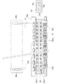
図5は、プラテン26の周辺を示す平面図である。プラテン26は、主走査の方向に、このプリンタで使用可能な印刷用紙Pの最大幅よりも長く設けられている。そして、プラテン26の上流には、上流側紙送りローラ25a、25bが設けられている。上流側紙送りローラ25aが一つの駆動ローラであるのに対し、上流側紙送りローラ25bは自由に回転する複数の小ローラである。また、プラテンの下流には、下流側紙送りローラ25c、25dが設けられている。下流側紙送りローラ25cが駆動軸に設けられた複数のローラであり、下流側紙送りローラ25dは自由に回転する複数の小ローラである。下流側紙送りローラ25dの外周面には、回転軸方向に平行に溝が設けられている。すなわち、下流側紙送りローラ25dは、外周面に放射状に歯(溝と溝の間の部分)を有しており、回転軸方向から見た場合に歯車状の形状に見える。この下流側紙送りローラ25dは、通称「ギザローラ」と呼ばれ、印刷用紙Pをプラテン26上に押しつける役割を果たす。なお、下流側紙送りローラ25cと上流側紙送りローラ25aとは、外周の速さが等しくなるように同期して回転する。
FIG. 5 is a plan view showing the periphery of the
印刷ヘッド28は、これらの上流側紙送りローラ25a、25bおよび下流側紙送りローラ25c、25dに挟まれたプラテン26上を主走査において往復動する。印刷用紙Pは、上流側紙送りローラ25a、25bおよび下流側紙送りローラ25c、25dに保持され、その間の部分をプラテン26の上面によって印刷ヘッド28のノズル列と向かい合うように支持される。そして、上流側紙送りローラ25a、25bおよび下流側紙送りローラ25c、25dによって副走査送りを実施されて、印刷ヘッド28のノズルから吐出されるインクにより順次画像を記録される。
The
また、プラテン26には、副走査方向の上流側および下流側にそれぞれ上流側溝部26fと下流側溝部26rが設けられている。上流側溝部26fと下流側溝部26rは、それぞれ主走査方向に沿って、このプリンタで使用可能な印刷用紙Pの最大幅よりも長く設けられている。そして、上流側溝部26fと下流側溝部26rの底部にはそれぞれインク滴Ipを受けてこれを吸収するための吸収部材27f,27rが配されている。そして、下流側溝部26rは、印刷ヘッド28上のノズルNzのうち最下流のノズルを含む下流側の一部のノズル群Nr(図5において斜線で示す部分のノズル)と向かい合う位置に設けられている。そして、上流側溝部26fは、印刷ヘッド28上のノズルのうち最上流のノズルを含む上流側の一部のノズル群Nf(図5において図示せず)と向かい合う位置に設けられている。上流側溝部26fと下流側溝部26rとが、特許請求の範囲にいう「第1の溝部」に相当する。
The
また、プラテン26には、上流側溝部26fと下流側溝部26rとのそれぞれの両端を結ぶように副走査方向に延びる、左側溝部26aと右側溝部26bとが設けられている。左側溝部26aと右側溝部26bとは、印刷ヘッド上のノズル列からのインク滴の着弾範囲よりも長く副走査の方向の範囲に設けられている。そして、左側溝部26aと右側溝部26bは、それぞれの中心線同士の(主走査方向の)間隔が、プリンタ22で記録可能な印刷用紙Pのうち、主走査方向についての幅が最大の印刷用紙Pの幅に等しくなるように設けられている。なお、左側溝部26aと右側溝部26bは、プリンタ22で使用可能な最大幅の印刷用紙Pがガイド29a,29bによってガイドされる所定の主走査位置にあるとき、印刷用紙Pの主走査の方向の一方の側端部Paが左側溝部26a上に位置し、他方の側端部Pbが右側溝部26b上に位置するように設けられていればよい。したがって、上記のように、印刷用紙Pが定位置にあるとき、その側端部が左側溝部26aと右側溝部26bの中心線上にある態様以外に、印刷用紙Pの側端部が左側溝部26aと右側溝部26bの中心線よりも内側や外側に位置するように設けられていてもよい。この左側溝部26aと右側溝部26bが、特許請求の範囲にいう「第2の溝部」に相当する。これら上流側溝部26f、下流側溝部26r、左側溝部26aおよび右側溝部26bは互いに接続されており、四辺形の溝部を構成する。
Further, the
また、プラテン26には、上流側溝部26fと下流側溝部26rとのそれぞれの中間部分を結ぶように副走査方向に延びる、右側溝部26b2,26b3が設けられている。右側溝部26b2は、左側溝部26aに対して、それぞれの中心線同士の間隔が、プリンタ22で記録可能な印刷用紙Pのうち主走査方向についての幅が最大のものよりも幅が小さい、所定の印刷用紙Pの幅に等しくなるように設けられている。右側溝部26b3についても同様である。プリンタ22が縦配置A3サイズまで印刷可能なものであるとすれば、左側溝部26aと右側溝部26bの中心線の間隔は、A3サイズの短辺の長さである。このとき、例えば、左側溝部26aと右側溝部26b2の中心線の間隔は、B4サイズの短辺の長さとすることができ、左側溝部26aと右側溝部26b3の中心線の間隔は、A4サイズの短辺の長さとすることができる。なお、これら以外に、A5サイズに対応させた右側溝部、はがきサイズに対応させた右側溝部などを設けることもできる。これらの左側溝部26aと右側溝部26bの組、左側溝部26aと右側溝部26b2の組、左側溝部26aと右側溝部26bの組が、特許請求の範囲にいう「一対の第2の溝部」に相当する。
Further, the
これらの各溝部の底部にはインク滴Ipを受けてこれを吸収するための吸収部材27が配されている。以下、それぞれの溝部の吸収部材27の符号を、各溝部の符号と対応させて、27f,27r,27a,27b,27b2,27b3と記載することがある。
An absorbing
印刷用紙Pは、上流側紙送りローラ25a、25bおよび下流側紙送りローラ25c、25dによって副走査送りを実施されているときには、上流側溝部26fと下流側溝部26rの開口上を通過していく。また、印刷用紙Pは、プラテン26上において、左側端部Paは左側溝部26a上に位置し、右側端部Pbは各印刷用紙の幅に応じて、右側溝部26b,26b2,26b3上に位置するように、ガイド29a,29bによって主走査方向について位置決めされている。
When the sub-scan feed is performed by the upstream
次に、プリンタ22の制御回路40(図3参照)の内部構成を説明する。制御回路40の内部には、CPU41、PROM42、RAM43の他、コンピュータ90とのデータのやり取りを行うPCインターフェイス45と、インク吐出用ヘッド61〜66にインクドットのON、OFFの信号を出力する駆動用バッファ44などが設けられており、これらの素子および回路はバスで相互に接続されている。制御回路40は、コンピュータ90で処理されたドットデータを受け取り、これを一時的にRAM43に蓄え、所定のタイミングで駆動用バッファ44に出力する。このRAM43が、特許請求の範囲にいう「印刷データ記憶部」に相当する。
Next, the internal configuration of the control circuit 40 (see FIG. 3) of the
以上説明したハードウェア構成を有するプリンタ22は、紙送りモータ23により用紙Pを搬送しつつ、キャリッジ31をキャリッジモータ24により往復動させ、同時に印刷ヘッド28の各ノズルユニットのピエゾ素子を駆動して、各色インク滴Ipの吐出を行い、インクドットを形成して用紙P上に多色の画像を形成する。
The
なお、本実施例のプリンタにおいては、印刷用紙Pの上端Pfを下流側溝部26r上で印刷し、下端Prを上流側溝部26f上で印刷するために、印刷用紙の上端近傍と下端近傍において、印刷用紙の中間部分とは異なる印刷処理が行われる。この明細書では、印刷用紙の中間部分における印刷処理を「中間処理」と呼び、また、印刷用紙の上端近傍における印刷処理を「上端処理」、印刷用紙の下端近傍における印刷処理を「下端処理」と呼ぶ。また、上端処理と下端処理とをまとめて呼ぶときには「上下端処理」と呼ぶ。
In the printer of this embodiment, the upper end Pf of the printing paper P is printed on the
B2.画像の記録領域:
図6は、画像の記録領域Rと印刷用紙Pとの関係を示す説明図である。本実施例では、印刷用紙Pの上端Pfを超えて印刷用紙Pの外側まで画像の記録領域Rを設定する。また、印刷用紙Pの下端Pr、左側端Pa、右側端Pbについても同様に、印刷用紙Pの端を超えて印刷用紙Pの外側まで画像の記録領域Rを設定する。したがって、本実施例においては、印刷時の画像の記録領域Rと印刷用紙Pの大きさ、及び記録領域Rの想定位置と印刷用紙Pの配置の関係は、図6に示すようになる。以下、画像の記録領域を「拡張領域R」と呼ぶ。なお、印刷用紙Pの左側端Pa、右側端Pbの左右の名称については、プリンタ22の左右の名称と対応させたため、印刷用紙Pにおいては、実際の左右と左側端Pa、右側端Pbの名称とが逆になっている。
B2. Image recording area:
FIG. 6 is an explanatory diagram showing the relationship between the image recording region R and the printing paper P. In this embodiment, the image recording area R is set beyond the upper end Pf of the printing paper P to the outside of the printing paper P. Similarly, for the lower end Pr, the left end Pa, and the right end Pb of the printing paper P, the image recording area R is set beyond the end of the printing paper P to the outside of the printing paper P. Therefore, in the present embodiment, the recording area R of the image at the time of printing and the size of the printing paper P, and the relationship between the assumed position of the recording area R and the arrangement of the printing paper P are as shown in FIG. Hereinafter, an image recording area is referred to as an “extended area R”. Since the left and right names of the left edge Pa and right edge Pb of the printing paper P correspond to the left and right names of the
拡張領域Rの、印刷用紙Pの左右側端Pa,Pbを超えて設定される部分の主走査方向(図6の左右方向)の寸法は、印刷用紙Pの主走査方向の寸法によって異なる。拡張領域Rのうちの、印刷用紙Pの左側端Paを超えて設定される部分を、記録領域の外左端部Rapと呼び、右側端Pbを超えて設定される部分を、記録領域の外右端部Rbpと呼ぶ。ただし、外左端部Rapの幅Waと、外右端部Rbpの幅Wbとは等しいものとする。なお、WaとWbを異なる値としてもよい。 The dimension in the main scanning direction (left and right direction in FIG. 6) of the portion of the expansion region R that is set beyond the left and right side edges Pa and Pb of the printing paper P differs depending on the dimensions of the printing paper P in the main scanning direction. A portion of the extended region R that is set beyond the left end Pa of the printing paper P is called an outer left end portion Rap of the recording region, and a portion that is set beyond the right end Pb is the outer right end of the recording region. This is called a part Rbp. However, the width Wa of the outer left end portion Rap is equal to the width Wb of the outer right end portion Rbp. Wa and Wb may be different values.
これに対して、拡張領域Rの、印刷用紙Pの上端Pf、下端Prを超えて設定される部分の副走査方向(図6の上下方向)の寸法は、印刷用紙Pの副走査方向の寸法および材質(紙以外の素材も含む)によって異なる。拡張領域Rのうちの、印刷用紙Pの上端Pfを超えて設定される部分を、記録領域の外上端部Rfpと呼び、下端Prを超えて設定される部分を、記録領域の外下端部Rrpと呼ぶ。 On the other hand, the dimension in the sub-scanning direction (vertical direction in FIG. 6) of the portion of the extended region R set beyond the upper end Pf and the lower end Pr of the printing paper P is the dimension in the sub-scanning direction of the printing paper P. And material (including materials other than paper). A portion of the extended region R that is set to exceed the upper end Pf of the printing paper P is called an outer upper end portion Rfp of the recording region, and a portion that is set to exceed the lower end Pr is the outer lower end portion Rrp of the recording region. Call it.
外上端部Rfpは、印刷ヘッド28に設けられたノズル列のうち、下流側溝部26rと向かい合う位置にあるノズル群Nr(図5参照)のみを使用して記録される。なお、ここで「特定のノズル群のみを使用する。」とは、その特定のノズル群以外のノズルを使用しない意味である。そして、特定のノズル群については、少なくとも一部が使用されていればよい。拡張領域Rのうち、印刷用紙Pの上端Pfから内側で外上端部Rfpと隣接する部分も、外上端部Rfpと同じ、ノズル群Nrのみで記録される。この部分を内上端部Rfqと呼ぶ。そして、外上端部Rfpと内上端部Rfqとをあわせて、拡張領域Rの上端部Rfと呼ぶ。一方、外下端部Rrpは、印刷ヘッド28に設けられたノズル列のうち、上流側溝部26fと向かい合う位置にあるノズル群Nfのみで記録される。印刷用紙Pの下端Prから内側で外下端部Rrpと隣接する部分も、外下端部Rrpと同じ、ノズル群Nfのみで記録される。この部分を内下端部Rrqと呼ぶ。そして、外下端部Rrpと内下端部Rrqとをあわせて、拡張領域Rの下端部Rrと呼ぶ。
The outer upper end portion Rfp is recorded using only the nozzle group Nr (see FIG. 5) in the position facing the
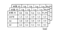
図7は、外上端部Rfp、内上端部Rfq、外下端部Rrp、内下端部Rrq、外左端部Rap、外右端部Rbpの寸法の例を示す表である。ここで、外上端部Rfpの長さをLfpとし、内上端部Rfqの長さをLfqとする。そして、外下端部Rrpの長さをLrpとし、内下端部Rrqの長さLrqとする。これらLfp,Lfq,Lrp,LrqおよびWa,Wbは、印刷用紙の種類(寸法や材質)に応じて変化する。図7においては、印刷用紙の材質P1,P2,P3についての拡張領域の寸法の情報が表の形で示されている。なお、印刷用紙の材質は、例えば、普通紙、フォトプリント紙、専用光沢フィルム、専用OHPシートなどとすることができる。これらは互いに副走査の際の滑りやすさが異なっており、一般に、副走査の際に生じる誤差の大きさが異なる。 FIG. 7 is a table showing examples of dimensions of the outer upper end Rfp, the inner upper end Rfq, the outer lower end Rrp, the inner lower end Rrq, the outer left end Rap, and the outer right end Rbp. Here, the length of the outer upper end Rfp is Lfp, and the length of the inner upper end Rfq is Lfq. The length of the outer lower end Rrp is Lrp, and the length of the inner lower end Rrq is Lrq. These Lfp, Lfq, Lrp, Lrq and Wa, Wb vary depending on the type (size and material) of the printing paper. In FIG. 7, information on the dimensions of the extended regions for the printing paper materials P1, P2, and P3 is shown in the form of a table. The material of the printing paper can be, for example, plain paper, photo print paper, a dedicated gloss film, a dedicated OHP sheet, or the like. These are different in slipperiness in the sub-scanning, and generally, the magnitudes of errors generated in the sub-scanning are different.
図8は、種類の異なる印刷用紙と拡張領域の関係を示す説明図である。図7のように、印刷用紙Pの四辺の端を超えて設定される、拡張領域の部分の寸法を定めると、拡張領域Rの大きさおよび印刷用紙Pに対する配置が定まる。拡張領域Rの各寸法は、印刷用紙Pの寸法、材質によって異なるので、印刷用紙Pと拡張領域Rの関係は図8(a)〜(f)のようになる。なお、記録領域Rは、各図においてそれぞれR1〜R6で示し、印刷用紙Pは、P1〜P6で示している。また、拡張領域Rの上端部Rf、下端部Rrについても、同様に符号1〜6を付している。
FIG. 8 is an explanatory diagram showing the relationship between different types of printing paper and extended areas. As shown in FIG. 7, when the dimensions of the extended region set beyond the four sides of the printing paper P are determined, the size of the extended region R and the arrangement with respect to the printing paper P are determined. Since the dimensions of the extended region R differ depending on the size and material of the printing paper P, the relationship between the printing paper P and the extended region R is as shown in FIGS. The recording area R is indicated by R1 to R6 in each figure, and the printing paper P is indicated by P1 to P6. Similarly, the upper end Rf and the lower end Rr of the extended region R are also denoted by
図8(d)における印刷用紙P4は、図8(a)における印刷用紙P1よりも大きい。よって、印刷用紙P4に画像を記録するための拡張領域R4は、印刷用紙P1の拡張領域R1よりも大きく設定される。また、印刷用紙P1,P2,P3は、サイズは同じであるがそれぞれ材質が異なっており、副走査における用紙の滑りやすさはP1,P2,P3の順に大きい。このため、それぞれの印刷用紙に対する拡張領域Rの副走査方向の長さは、R1,R2,R3の順に長くなっている。更に詳しくいえば、拡張領域Rのうち溝上のノズルで記録される上端部Rfと下端部Rrの副走査方向の長さが、R1,R2,R3の順に長くなっている。 The printing paper P4 in FIG. 8D is larger than the printing paper P1 in FIG. Therefore, the expansion area R4 for recording an image on the printing paper P4 is set larger than the expansion area R1 of the printing paper P1. Further, the printing papers P1, P2, and P3 have the same size but different materials, and the slipperiness of the paper in the sub-scanning is larger in the order of P1, P2, and P3. For this reason, the length in the sub-scanning direction of the extended region R for each print sheet is increased in the order of R1, R2, and R3. More specifically, the length in the sub-scanning direction of the upper end Rf and the lower end Rr recorded by the nozzle on the groove in the extended region R is increased in the order of R1, R2, and R3.
ここで、上端部Rfのうち外上端部Rfpと内上端部Rfqのいずれか一方のみの寸法を、印刷用紙の種類に応じて変えることとしてもよいが、両方の寸法を印刷用紙の種類に応じて変えることが好ましい。同様に、下端部Rrのうち外下端部Rrpと内下端部Rrqのいずれか一方の寸法のみを、印刷用紙の種類に応じて変えることとしてもよいが、両方の寸法を印刷用紙の種類に応じて変えることが好ましい。 Here, the size of only one of the outer upper end portion Rfp and the inner upper end portion Rfq of the upper end portion Rf may be changed according to the type of printing paper, but both dimensions may be changed according to the type of printing paper. It is preferable to change it. Similarly, only one of the outer lower end Rrp and the inner lower end Rrq of the lower end Rr may be changed according to the type of printing paper, but both dimensions may be changed according to the type of printing paper. It is preferable to change it.
図9は、印刷用紙Pの四辺の端を超えて設定される、拡張領域の部分のラスタ数、画素数の例を示す表である。拡張領域Rの大きさおよび印刷用紙Pに対する配置は、図6、図7に示すようにして定められるが、拡張領域テーブルEAT(図2参照)は、拡張領域Rに関する情報をラスタ数および画素数で記憶している。 FIG. 9 is a table showing an example of the number of rasters and the number of pixels in the extended area portion set beyond the edges of the four sides of the printing paper P. The size of the extension area R and the arrangement with respect to the printing paper P are determined as shown in FIGS. 6 and 7, but the extension area table EAT (see FIG. 2) stores information on the extension area R as the number of rasters and the number of pixels. I remember it.
たとえば、図7において、材質P1でA4サイズの印刷用紙の外上端部Rfpの副走査方向の長さLfpは、3.0mmである。副走査方向のラスタの記録密度および主走査方向の画素の記録密度が720dpi(dot / inch)である場合は、外上端部Rfpの副走査方向の長さLfpが3.0mmとなるようるためには、図9(a)に示すように、外上端部Rfpを85本のラスタで構成する必要がある。これに対して、ラスタの記録密度および主走査方向の画素の記録密度が1440dpiである場合は、Lfpが3.0mmとなるようるためには、図9(b)に示すように、外上端部Rfpを170本のラスタで構成する必要がある。ここで、ラスタ数は、(長さ/(1/記録密度))で求めることができる。例えば、記録密度が720dpiのときに外上端部Rfpの長さLfp[mm]をラスタ数で表す場合は、そのラスタ数は、((Lfp[mm]/25.4)/(1/720[dpi]))を整数の単位で四捨五入した値とすることができる。 For example, in FIG. 7, the length Lfp in the sub-scanning direction of the outer upper end Rfp of the A4 size printing paper made of the material P1 is 3.0 mm. When the raster recording density in the sub-scanning direction and the pixel recording density in the main scanning direction are 720 dpi (dot / inch), the length Lfp in the sub-scanning direction of the outer upper end Rfp is 3.0 mm. As shown in FIG. 9A, the outer upper end portion Rfp needs to be composed of 85 rasters. On the other hand, when the recording density of the raster and the recording density of the pixels in the main scanning direction are 1440 dpi, in order for Lfp to be 3.0 mm, as shown in FIG. The part Rfp needs to be composed of 170 rasters. Here, the number of rasters can be obtained by (length / (1 / recording density)). For example, when the recording density is 720 dpi and the length Lfp [mm] of the outer upper end Rfp is represented by the number of rasters, the number of rasters is ((Lfp [mm] /25.4) / (1/720 [ dpi])) can be rounded off to the nearest whole number.
同様に、図7において、材質P1ではがきサイズの印刷用紙の外左端部Rapの主走査方向の長さWaは、1.5mmである。主走査方向のラスタの記録密度および主走査方向の画素の記録密度が720dpi(dot / inch)である場合は、外左端部Rapの副走査方向の長さWaが1.5mmとなるようるためには、図9(a)に示すように、外左端部Rapを43個の画素で構成する必要がある。これに対して、ラスタの記録密度および主走査方向の画素の記録密度が1440dpiである場合は、外左端部Rapの副走査方向の長さLapが1.5mmとなるようるためには、図9(b)に示すように、外上端部Rfpを85個の画素で構成する必要がある。 Similarly, in FIG. 7, the length Wa in the main scanning direction of the outer left end portion Rap of the printing paper with the material P1 and the postcard size is 1.5 mm. When the recording density of the raster in the main scanning direction and the recording density of the pixels in the main scanning direction are 720 dpi (dot / inch), the length Wa in the sub-scanning direction of the outer left end Rap is 1.5 mm. As shown in FIG. 9A, the outer left end Rap needs to be composed of 43 pixels. On the other hand, when the recording density of the raster and the recording density of the pixels in the main scanning direction are 1440 dpi, the length Lap in the sub-scanning direction of the outer left end Rap is 1.5 mm. As shown in FIG. 9B, the outer upper end Rfp needs to be configured with 85 pixels.
すなわち、図9(a)および(b)に示すように、拡張領域テーブルEAT(図2参照)は、印刷モードごとに外上端部Rfp、内上端部Rfq、外下端部Rrp、内下端部Rrqのラスタ数、および外左端部Rap、外右端部Rbpの画素数で記憶している。そして、各印刷モードにおける同一種類の印刷用紙についての端部を構成するラスタの数は、各外上端部の副走査の方向の寸法が互いにほぼ等しくなるような値である。内上端部Rfq、外下端部Rrp、内下端部Rrqのラスタ数、および外左端部Rap、外右端部Rbpの画素数についても同様である。ここで、印刷媒体(印刷用紙)の「種類」が同一であるとは、印刷媒体の材質が同一であり、形状、寸法が同一である場合をいう。 That is, as shown in FIGS. 9A and 9B, the extended area table EAT (see FIG. 2) includes an outer upper end Rfp, an inner upper end Rfq, an outer lower end Rrp, and an inner lower end Rrq for each print mode. And the number of pixels of the outer left end Rap and the outer right end Rbp. The number of rasters constituting the edge of the same type of printing paper in each printing mode is a value such that the dimensions of the outer upper edge in the sub-scanning direction are substantially equal to each other. The same applies to the number of rasters in the inner upper end Rfq, outer lower end Rrp, inner lower end Rrq, and number of pixels in the outer left end Rap and outer right end Rbp. Here, the “type” of the printing medium (printing paper) is the same when the material of the printing medium is the same and the shape and dimensions are the same.
解像度変換モジュール97は、図9に示すような形態の情報を保持している拡張領域テーブルEATを参照して、拡張領域を決定する。そして、画像データを、指定された解像度でその拡張領域を記録できるようなデータに、変換する。その際、外上端部Rfpの長さLfpと、内上端部Rfqの長さLfqと、外下端部Rrpの長さLrpと、内下端部Rrqの長さLrqの長さと、外左端部Rapの幅Waと、外右端部Rbpの幅Wbとが定められることから、拡張領域Rの印刷用紙Pに対する配置も定められることになる。この拡張領域テーブルEATが、特許請求の範囲にいう「領域サイズ記憶部」に相当する。また、ハードウェアとしては、拡張領域テーブルEATが記憶されているメモリが、「領域サイズ記憶部」に相当する。そして、解像度変換モジュール97が、その処理の一部において、特許請求の範囲にいう「ラスタ数決定部」および「画素数決定部」として機能する。これらの機能部を図2においてラスタ数決定部97a、画素数決定部97bとして示す。
The
図10は、印刷用紙Pが傾いた場合の印刷用紙Pの下端Prと拡張領域Rとの関係を示す説明図である。実線が想定された印刷用紙Pの配置を示し、一点鎖線および二点鎖線が傾いた印刷用紙Pの位置を示している。印刷用紙Pがプラテン上において想定された姿勢から傾いた場合、印刷用紙Pの端の位置のずれ量は、印刷用紙Pの大きさによって異なる。すなわち、用紙が時計回りに回転した場合を例に説明すると、印刷用紙の一辺の一方の角の位置ずれd1は、他方の端の位置を基準とすると、d1=Wp・sinθ1となる。ここで、Wpは用紙の一辺の長さであり、θ1は用紙の傾き角の大きさである。すなわち、ずれ量d1は用紙の一辺の長さWpに比例する。用紙が反時計回りに回転した場合のずれd2についても、同様である。 FIG. 10 is an explanatory diagram showing the relationship between the lower end Pr of the printing paper P and the extended region R when the printing paper P is tilted. The arrangement of the printing paper P on which a solid line is assumed is shown, and the position of the printing paper P on which the one-dot chain line and the two-dot chain line are inclined is shown. When the printing paper P is inclined from the assumed posture on the platen, the amount of deviation of the end position of the printing paper P varies depending on the size of the printing paper P. That is, the case where the paper rotates clockwise will be described as an example. The positional deviation d1 of one corner of one side of the printing paper is d1 = Wp · sin θ1 when the position of the other end is used as a reference. Here, Wp is the length of one side of the paper, and θ1 is the size of the inclination angle of the paper. That is, the shift amount d1 is proportional to the length Wp of one side of the paper. The same applies to the deviation d2 when the sheet rotates counterclockwise.
第1実施例では、図7に示すように、印刷媒体の大きさによって、外上端部Rfp、内上端部Rfq、外下端部Rrp、内下端部Rrqおよび外左端部Rap、外右端部Rbpの大きさを定めている。すなわち、印刷媒体の大きさによって、拡張領域Rの大きさおよび印刷用紙Pに対する配置を変えている。このため、印刷用紙Pがプラテン上において想定された姿勢から傾いた場合にも、印刷用紙Pの上端Pfや下端Prが拡張領域Rの下端部Rrや上端部Rf内に収まるように、拡張領域Rの大きさおよび印刷用紙Pに対する配置を定めることができる。図10においては、印刷用紙Pの下端Prは、印刷用紙Pがいずれの向きに傾いた場合も、下端部Rr(外下端部Rrp+内下端部Rrq)内に収まっている。よって、印刷用紙Pの端に余白ができることはなく、プラテンをインク滴で汚すこともない。 In the first embodiment, as shown in FIG. 7, the outer upper end Rfp, the inner upper end Rfq, the outer lower end Rrp, the inner lower end Rrq, the outer left end Rap, and the outer right end Rbp depend on the size of the printing medium. The size is determined. That is, the size of the extended region R and the arrangement with respect to the printing paper P are changed depending on the size of the printing medium. For this reason, even when the printing paper P is tilted from the assumed posture on the platen, the extended area so that the upper end Pf and the lower end Pr of the printing paper P are within the lower end Rr and the upper end Rf of the extended area R. The size of R and the arrangement with respect to the printing paper P can be determined. In FIG. 10, the lower end Pr of the printing paper P is within the lower end Rr (outer lower end Rrp + inner lower end Rrq) regardless of the orientation of the printing paper P. Therefore, no margin is formed at the edge of the printing paper P, and the platen is not stained with ink droplets.
このように第1実施例では、印刷用紙Pが傾いて下端の一部が下流側にずれた場合にも、印刷用紙Pの端に余白ができる可能性が少ない。そして、印刷用紙Pの一部が上流側にずれた場合にも、プラテンをインク滴で汚す可能性が少ない。また、印刷用紙Pの大きさに対して適切な大きさに記録領域を定めることで、印刷媒体の大きさに対して、不必要に大きい領域にインク滴を吐出することによって、印刷の際に無駄な時間を使うことがないようにすることができる。 As described above, in the first embodiment, even when the printing paper P is inclined and a part of the lower end is shifted to the downstream side, there is little possibility that a margin is formed at the edge of the printing paper P. Even when a part of the printing paper P is shifted to the upstream side, the platen is less likely to be stained with ink droplets. In addition, by setting the recording area to an appropriate size with respect to the size of the printing paper P, by ejecting ink droplets to an area that is unnecessarily large with respect to the size of the printing medium, printing is performed. You can avoid wasting time.
なお、ここでは、印刷用紙Pの下端Prについて図示して説明したが、拡張領域Rと印刷用紙Pの傾きの関係は、上端Pf側、および左右端Pa,Pb側についても同様である。ただし、上端Pf側については、上流側へのずれについての説明と、下流側へのずれについての説明が入れ替わることになる。すなわち、印刷用紙Pが上流側にずれた場合にも、印刷用紙Pの端に余白ができる可能性が少ない。そして、印刷用紙Pが下流側にずれた場合にも、プラテンをインク滴で汚す可能性が少ない。 Here, the lower end Pr of the printing paper P has been illustrated and described, but the relationship between the expansion region R and the inclination of the printing paper P is the same for the upper end Pf side and the left and right ends Pa and Pb. However, for the upper end Pf side, the description about the shift to the upstream side and the description about the shift to the downstream side are interchanged. That is, even when the printing paper P is shifted to the upstream side, there is little possibility that a margin is formed at the end of the printing paper P. Even when the printing paper P is shifted to the downstream side, the platen is less likely to be stained with ink droplets.
図11は、副走査送りにずれが生じた場合の印刷用紙Pの下端Prと拡張領域Rとの関係を示す説明図である。実線が想定された印刷用紙Pの配置を示し、一点鎖線および二点鎖線が副走査送りにずれが生じた場合の印刷用紙Pの位置を示している。印刷媒体が想定量よりも少なく送られた場合のずれがd3であり、印刷媒体が想定量よりも多く送られた場合のずれがd4である。印刷媒体の材質が異なる場合、副走査送りのずれ量が異なってくることがある。このずれ量は、印刷媒体の副走査における滑りやすさと、印刷媒体の副走査方向の寸法によって異なってくる。 FIG. 11 is an explanatory diagram showing the relationship between the lower end Pr of the printing paper P and the extended region R when a deviation occurs in the sub-scan feed. The solid line indicates the arrangement of the printing paper P, and the one-dot chain line and the two-dot chain line indicate the position of the printing paper P when the sub-scan feed shifts. The deviation when the print medium is sent less than the assumed amount is d3, and the deviation when the print medium is sent more than the assumed amount is d4. When the material of the print medium is different, the amount of sub-scan feed deviation may be different. The amount of deviation differs depending on the slipperiness in the sub-scan of the print medium and the size of the print medium in the sub-scan direction.
第1実施例では、図7に示すように、印刷媒体の材質および寸法に応じて外上端部Rfp、内上端部Rfq、外下端部Rrp、内下端部Rrq、外左端部Rap、外右端部Rbpの大きさを定めている。すなわち、印刷媒体の材質および寸法に応じて、拡張領域Rの大きさおよび印刷用紙Pに対する配置を変えている。このため、材質や大きさが異なる印刷媒体の種類ごとに、印刷用紙Pの送りがずれても上端Pfや下端Prが拡張領域Rの下端部Rrや上端部Rf内に収まるように、適切な拡張領域Rの大きさおよび印刷用紙Pに対する配置を定めることができる。図11においては、印刷用紙Pの下端Prは、印刷用紙Pがいずれの方向にずれた場合も、下端部Rr(外下端部Rrp+内下端部Rrq)内に収まっている。よって、印刷用紙Pの端に余白ができることはなく、プラテンをインク滴で汚すこともない。 In the first embodiment, as shown in FIG. 7, the outer upper end Rfp, the inner upper end Rfq, the outer lower end Rrp, the inner lower end Rrq, the outer left end Rap, and the outer right end according to the material and dimensions of the printing medium. The size of Rbp is determined. That is, the size of the extended region R and the arrangement with respect to the printing paper P are changed according to the material and dimensions of the printing medium. For this reason, for each type of printing medium having a different material and size, an appropriate value is set so that the upper end Pf and the lower end Pr are within the lower end Rr and the upper end Rf of the extended region R even if the feeding of the printing paper P is shifted. The size of the extended region R and the arrangement with respect to the printing paper P can be determined. In FIG. 11, the lower end Pr of the printing paper P is within the lower end Rr (outer lower end Rrp + inner lower end Rrq) when the printing paper P is displaced in any direction. Therefore, no margin is formed at the edge of the printing paper P, and the platen is not stained with ink droplets.
このように第1実施例では、副走査において滑りが予想よりも大きく、印刷用紙Pが下流側にずれた場合にも、印刷用紙Pの端に余白ができる可能性が少ない。そして、印刷用紙Pが上流側にずれた場合にも、プラテンをインク滴で汚す可能性が少ない。また、副走査送りの際に精度よい紙送りがなされる印刷媒体に対して、不必要に大きい領域にインク滴を吐出することによって、印刷の際に無駄な時間を使うこともない。なお、ここでは、印刷用紙Pの下端Prについて図示して説明したが、拡張領域Rと印刷用紙Pの副走査送りのずれの関係は、上端Pf側についても同様である。 As described above, in the first embodiment, slippage is larger than expected in the sub-scanning, and even when the printing paper P is shifted to the downstream side, there is little possibility that a margin is formed at the end of the printing paper P. Even when the printing paper P is shifted to the upstream side, there is little possibility that the platen is stained with ink droplets. In addition, by ejecting ink droplets onto an unnecessarily large area on a printing medium that is accurately fed during sub-scan feeding, useless time is not used in printing. Here, the lower end Pr of the printing paper P has been illustrated and described, but the relationship between the extension region R and the sub-scan feed of the printing paper P is the same on the upper end Pf side.
また、拡張領域テーブルEAT(図2参照)は、図9(a)および(b)に示すように、印刷モードごとに、外上端部Rfp、内上端部Rfq、外下端部Rrp、内下端部Rrqのラスタ数、および外左端部Rap、外右端部Rbpの画素数で記憶している。このため、印刷用紙Pの端を超えて設定される拡張領域Rの各部の寸法を一定に保つことができる。 Further, as shown in FIGS. 9A and 9B, the extended area table EAT (see FIG. 2) includes an outer upper end Rfp, an inner upper end Rfq, an outer lower end Rrp, and an inner lower end for each printing mode. The number of Rrq rasters and the number of pixels at the outer left end Rap and the outer right end Rbp are stored. For this reason, the dimension of each part of the extended region R set beyond the edge of the printing paper P can be kept constant.
B3.印刷処理の手順:
図12は、アプリケーションプログラムが印刷命令を発した後の、ドライバに対するユーザの手続きを示すフローチャートである。図13および図14は、印刷用紙の材質を指示するウィンドウを示す図である。ユーザが、アプリケーションプログラム95に対して印刷を指示すると、アプリケーションプログラム95は、プリンタドライバ96に対して印刷命令を発する。すると、プリンタドライバ96は、CRT21(図2参照)に、「印刷」のウィンドウを表示する。ユーザが「印刷」のウィンドウから「プリンタのプロパティ」のアイコンをクリックすると、図13に示すようなウィンドウが表示される。
B3. Printing process steps:
FIG. 12 is a flowchart showing the user's procedure for the driver after the application program issues a print command. 13 and 14 are views showing windows for instructing the material of the printing paper. When the user instructs the
ユーザは、図12のステップS1において、まず、図13のウィンドウの複数のタブのうちの左上の「基本設定」のタブを選択し、「用紙種類」の項目において用紙の種類(材質)を選択する。なお、図13のウィンドウにおいては、「用紙種類」とは、本明細書における印刷用紙の「材質」を意味する。図13においては、「普通紙」が選択されている。たとえば、ここで、「フォトプリント紙」を選択したとすると、図13のウィンドウは、図14のようになる。 In step S1 of FIG. 12, the user first selects the “basic setting” tab at the upper left of the plurality of tabs of the window of FIG. 13, and selects the paper type (material) in the “paper type” item. To do. In the window of FIG. 13, “paper type” means “material” of the printing paper in this specification. In FIG. 13, “plain paper” is selected. For example, if “photo print paper” is selected, the window shown in FIG. 13 is as shown in FIG.
図15は、画像の記録密度を指示するウィンドウを示す図である。印刷用紙を選択した後、図14のウィンドウの中段の「モード設定」において「詳細設定」にチェックを入れる。すると、ウィンドウは図15のように変化し、記録密度(印刷モード)の窓が現れる。ユーザは、ステップS2(図12参照)において、たとえば、図15に示すように「高精細」の印刷モードを選択する。「高精細」が選択された場合は、通常の記録密度よりも高い記録密度で印刷が行われる。 FIG. 15 is a diagram showing a window for instructing the recording density of an image. After selecting the printing paper, “Detailed setting” is checked in “Mode setting” in the middle of the window of FIG. Then, the window changes as shown in FIG. 15, and a recording density (print mode) window appears. In step S2 (see FIG. 12), for example, the user selects the “high definition” print mode as shown in FIG. When “high definition” is selected, printing is performed at a recording density higher than the normal recording density.
なお、ユーザは、「モード設定」において「詳細設定」を選択せずに、「推奨設定」を選択した場合にも、図14に示すように、「きれい」と「速い」のいずれかを選択することができる。いずれが選択された場合も記録密度は通常のままであるが、「速い」が選択された場合はマイクロウィーブ印刷は行われず、双方向印刷が行われる。逆に、「きれい」が選択された場合は、マイクロウィーブ印刷が行われ、単方向印刷が行われる(双方向印刷は行われない)。「マイクロウィーブ印刷」は、「オーバーラップ印刷」ともいわれ、一つのラスタ中の画素を複数回の主走査でそれぞれ異なるノズルを使用して印刷する印刷方式である。「単方向印刷」は、一方向の主走査でのみドットの形成を行う印刷方式であり、「双方向印刷」は、往復の主走査でドットの形成を行う印刷方式である。第1実施例では、画素の記録密度に応じて拡張領域の各ラスタ数、画素数を設定しているが(図9参照)、これらの印刷の方法も考慮して拡張領域の各ラスタ数、画素数を設定するようにすることもできる。 In addition, when the user selects “recommended setting” without selecting “detailed setting” in “mode setting”, the user selects either “clean” or “fast” as shown in FIG. can do. Regardless of which is selected, the recording density remains normal, but when “fast” is selected, microweave printing is not performed and bidirectional printing is performed. On the contrary, when “clean” is selected, microweave printing is performed, and unidirectional printing is performed (bidirectional printing is not performed). “Microweave printing” is also referred to as “overlap printing”, and is a printing method in which pixels in one raster are printed using different nozzles in a plurality of main scans. “Unidirectional printing” is a printing method in which dots are formed only by main scanning in one direction, and “bidirectional printing” is a printing method in which dots are formed by reciprocating main scanning. In the first embodiment, the number of rasters and the number of pixels in the extended area are set in accordance with the recording density of the pixels (see FIG. 9). It is also possible to set the number of pixels.
図16は、印刷用紙のサイズを指示するウィンドウを示す図である。ステップS2で印刷モードを選択した後、ユーザは、ステップS3において左端から2番目の「用紙設定」のタブを選択し、図16に示すように、「用紙サイズ」の項目において用紙のサイズを選択する。図16においては、「A4」が選択されている。 FIG. 16 is a diagram showing a window for instructing the size of the printing paper. After selecting the print mode in step S2, the user selects the second “paper setting” tab from the left end in step S3, and selects the paper size in the “paper size” item as shown in FIG. To do. In FIG. 16, “A4” is selected.
その後、図16のウィンドウ下段の「OK」のアイコンをクリックし、「印刷」のウィンドウの「OK」のアイコンをクリックする。すると、プリンタドライバ96は、解像度変換モジュール97による解像度変換を開始し、印刷が実行される(ステップS4)。なお、以上で説明したステップS1〜S3の指示は、図12に示した順番に限られるものではなく、ステップS2、ステップS1、ステップS3の順に行うこととしてもよい。すなわち、印刷を実行する前に用紙の材質、大きさおよび印刷モードが指示されれば、その指示の順番はどのようであってもよい。また、図13〜図16に示したような、ユーザによるプリンタドライバ96への各指示(選択)のためのユーザインターフェイス画面は、プリンタドライバ96によってCRT21に表示される。すなわち、プリンタドライバ96が、特許請求の範囲にいう「ユーザインターフェイス部」として機能する。この機能部としての「ユーザインターフェイス部」を、図2においてユーザインターフェイス部96aとして示す。また、ユーザインターフェイス画面を通じたユーザによるプリンタドライバ96への各指示(選択)は、マウス13のほか、キーボード14(図2参照)を通じてもなされる。すなわち、これらマウス13、キーボード14が入力部として機能する。
Thereafter, the “OK” icon at the bottom of the window in FIG. 16 is clicked, and the “OK” icon in the “Print” window is clicked. Then, the
B4.ドットの形成:
(i)上端処理:
図17は、印刷用紙の上端(先端)近傍において、各ラスタがどのノズルによってどのように記録されていくかを示す説明図である。ここでは、説明を簡単にするため、1列のノズル列のみを使用して説明する。そして、1列のノズル列は8個のノズルを有するものとする。主走査の際には、各ノズルが一つのラスタの記録を担当する。ここで、「ラスタ」とは、主走査方向に並ぶ画素の列である。そして、「画素」とは、インク滴を着弾させドットを記録する位置を規定するために、印刷媒体上に仮想的に定められた方眼状の升目である。ここでは、各ノズルは3ラスタ分の間隔をあけて配されているものとする。
B4. Dot formation:
(I) Upper end processing:
FIG. 17 is an explanatory diagram showing how each raster is recorded by which nozzle in the vicinity of the upper end (front end) of the printing paper. Here, in order to simplify the description, description will be made using only one nozzle row. One nozzle row has eight nozzles. During main scanning, each nozzle is responsible for recording one raster. Here, the “raster” is a column of pixels arranged in the main scanning direction. The “pixel” is a square grid virtually defined on the print medium in order to define the position where the ink droplet is landed and the dot is recorded. Here, it is assumed that the nozzles are arranged at intervals of 3 rasters.
図17において、縦に並ぶ1列の升目は、印刷ヘッド28を表している。各升目の中の1〜8の数字が、ノズル番号を示している。明細書中では、これらの番号に「#」を付して各ノズルを表す。図17では、時間とともに副走査方向に相対的に送られる印刷ヘッド28を、順に左から右にずらして示している。図17に示すように、上端処理においては、1ドットづつの副走査送りを7回繰り返す。なお、副走査送り量の単位の「ドット」は、副走査方向の印刷解像度に対応する1ドット分のピッチを意味しており、これはラスタのピッチとも等しい。
In FIG. 17, one row of cells arranged vertically represents the
その後、中間処理に移行して、5ドット、2ドット、3ドット、6ドットの送りをその順に繰り返す。このように異なる送り量を組み合わせて副走査を行う方式を「変則送り」という。上記のような副走査送りを実施すると、一部のラスタを除き、各ラスタはそれぞれ二つのノズルで記録される。すなわち、本実施例では、各ラスタは、二つのノズルで印刷される。例えば、図17において、上から5番目のラスタは、#2のノズルと#1のノズルとで記録される。この際、#2のノズルは例えば偶数アドレスの画素を記録し、#1のノズルは奇数アドレスの画素を記録する。また、上から9番目のラスタは、#3のノズルと#2のノズルとで記録される。このように、一つのラスタ内の画素を複数のノズルで分担して印刷する方式を「オーバーラップ印刷」という。オーバーラップ印刷においては、一つのラスタは、印刷ヘッドに対する印刷用紙の副走査方向の位置が互いに異なる複数回の主走査において、そのラスタ上を通過する複数のノズルによってドットを記録される。 Thereafter, the process shifts to intermediate processing, and the feeding of 5 dots, 2 dots, 3 dots, and 6 dots is repeated in that order. A method of performing sub-scanning by combining different feed amounts in this way is called “anomalous feed”. When the sub-scan feed as described above is performed, each raster is recorded by two nozzles except for some rasters. That is, in this embodiment, each raster is printed by two nozzles. For example, in FIG. 17, the fifth raster from the top is recorded by the # 2 nozzle and the # 1 nozzle. At this time, the # 2 nozzle records, for example, even address pixels, and the # 1 nozzle records odd address pixels. The ninth raster from the top is recorded by the # 3 nozzle and the # 2 nozzle. In this manner, a method of printing by sharing pixels in one raster by a plurality of nozzles is called “overlap printing”. In overlap printing, a single raster is recorded with dots by a plurality of nozzles passing over the raster in a plurality of main scans at different positions in the sub-scanning direction of the printing paper with respect to the print head.
一方、図17において、最上段から4本のラスタは、印刷の際の主走査において#1のノズルが1度通過するだけである。したがって、これらのラスタについては、二つのノズルで画素を分担して印刷することができない。よって、本実施例では、これら4本のラスタは、画像を記録するために使用することはしないものとする。すなわち、本実施例において画像を記録するために使用できるラスタは、印刷ヘッド28上のノズルがドットを記録しうるラスタのうち、副走査方向上流の端から5番目以降のラスタとする。この画像を記録するために使用できるラスタの領域を「印刷可能領域」と呼ぶ。また、画像記録のために使用しないラスタの領域を「印刷不可領域」と呼ぶ。図17においては、印刷ヘッド28上のノズルがドットを記録しうるラスタについて、上から順に付した番号を、図の左側に記載している。以降、上端処理のドットの記録を説明する図面においても同様である。なお、図において太枠で囲まれたノズルが、ラスタにドットを記録するノズルである。
On the other hand, in FIG. 17, the four rasters from the top are only passed once by the # 1 nozzle in the main scan during printing. Therefore, for these rasters, it is not possible to print by sharing pixels with two nozzles. Therefore, in this embodiment, these four rasters are not used for recording an image. That is, the rasters that can be used to record an image in the present embodiment are the fifth and subsequent rasters from the upstream end in the sub-scanning direction among the rasters in which the nozzles on the
また、図17において、上から13番目や15番目のラスタは、印刷の際の主走査において3個のノズルが通過する。そのような、印刷において三つ以上のノズルが通過するラスタについては、その中の二つのノズルのみがドットを記録するものとする。それらのラスタは、できるだけ中間処理に移行した後にそのラスタ上を通過するノズルで記録することが好ましい。中間処理においては、変則送りが行われており、隣り合うラスタ上を通過するノズルの組み合わせが違ってくるため、1ドットづつの定則送りが行われる上端処理に比べて、印刷結果が高画質となることが期待できるからである。 In FIG. 17, the 13th and 15th rasters from the top pass through three nozzles in the main scanning during printing. For such a raster in which three or more nozzles pass during printing, only two of the nozzles record dots. These rasters are preferably recorded by nozzles that pass over the raster after having moved to intermediate processing as much as possible. In the intermediate processing, irregular feeding is performed, and the combination of nozzles passing on adjacent rasters is different, so that the printing result is higher in image quality than the upper end processing in which regular feeding is performed dot by dot. Because it can be expected.
本実施例では、印刷用紙の上端まで余白なく画像を記録する。前述のように、本実施例においては、印刷ヘッド28上のノズルがドットを記録しうるラスタのうち、副走査方向上流の端から5番目以降のラスタ(印刷可能領域)を使用して、画像を記録することができる。したがって、印刷用紙の上端ぎりぎりの位置に上記端から5番目のラスタが位置するように、印刷ヘッド28に対して印刷用紙を配置してドットの記録を開始することとすれば、理論上は、印刷用紙の上端いっぱいまで画像を記録することができる。しかし、副走査送りの際には送り量について誤差が生じる場合がある。また、印刷ヘッドの製造誤差などによりインク滴の吐出方向がずれる場合もある。そのような理由から印刷用紙上へのインク滴の着弾位置がずれた場合についても、印刷用紙の上端に余白が生じないようにすることが好ましい。よって本実施例では、印刷に使用する画像データDは、印刷ヘッド28上のノズルがドットを記録しうるラスタのうち、副走査方向上流の端から5番目のラスタから設定し、一方で、印刷用紙Pの上端が、副走査方向上流の端から7番目のラスタの位置にある状態から印刷を開始することとする。したがって、印刷開始時の各ラスタに対する印刷用紙上端の想定位置は、図17に示すように、副走査方向上流の端から7番目のラスタの位置である。
In this embodiment, an image is recorded without a margin up to the upper end of the printing paper. As described above, in the present embodiment, among the rasters on which the nozzles on the
すなわち、本実施例では、印刷用紙Pの上端Pfを超えて印刷用紙Pの外側まで設定する拡張領域Rの外上端部Rfp(図6参照)の幅Lfpは、2ラスタ分である。また、印刷用紙Pの下端Prを超えて印刷用紙Pの外側ま設定する拡張領域Rの外下端部Rrp(図6参照)の幅Lrpも、同様に2ラスタ分である。下端側については後に詳述する。 That is, in the present embodiment, the width Lfp of the outer upper end portion Rfp (see FIG. 6) of the extended region R set beyond the upper end Pf of the printing paper P to the outside of the printing paper P is two rasters. Similarly, the width Lrp of the outer lower end portion Rrp (see FIG. 6) of the extended region R set to the outside of the print paper P beyond the lower end Pr of the print paper P is also two rasters. The lower end side will be described in detail later.
図18は、印刷開始時の印刷ヘッド28と印刷用紙Pの関係を示す側面図である。ここでは、プラテン26の中央支持部26cは、印刷ヘッド28の#2のノズルから数えて2ラスタ分後ろの位置から、#7のノズルから数えて2ラスタ分前の位置までの範囲R26に設けられているものとする。したがって、印刷用紙がない状態で各ノズルからインク滴Ipを吐出させた場合でも、#1,#2,#7,#8のノズルからのインク滴はプラテン26に着弾することはない。
FIG. 18 is a side view showing the relationship between the
図5において、印刷ヘッド28の斜線で示した部分のノズル群Nrが、#1、#2のノズルが位置する部分である。主走査の際にそれらのノズルが通過する部分の下方には、下流側溝部26rが設けられており、下流側溝部26r上の一点鎖線で示す位置に印刷用紙Pの上端Pfがあるときに、印刷が開始される。
In FIG. 5, the portion of the nozzle group Nr indicated by the diagonal lines of the
前述のように、印刷開始時において、印刷用紙Pの上端Pfは、印刷ヘッド28上のノズルがドットを記録しうるラスタのうち、副走査方向上流の端から7番目のラスタの位置にある。すなわち、図18を使用して説明すれば、印刷用紙Pの上端は、#1のノズルから数えて6ラスタ分後ろの位置にあることとなる。なお、図18においては、画像データ上に想定されたラスタの位置を破線で示している。しがたって、この状態から印刷を開始することとすると、印刷可能領域の最上段のラスタ(図17において、上から5番目のラスタ)が#2のノズルで記録されるはずであるが、#2のノズル下方にはまだ印刷用紙Pはない。したがって、印刷用紙Pが上流側紙送りローラ25a,25bによって正確に送られていれば、#2のノズルから吐出されたインク滴Ipは、そのまま下流側溝部26rに落下することとなる。また、この印刷可能領域の最上段のラスタは、図17に示すように、4回の1ドット送りの後、#1のノズルによっても記録されることとなっている。しかし、同様に、4回の1ドット送りが実施された段階では、#1のノズル下方にはまだ印刷用紙Pはない。よって、そのときに#1のノズルから吐出されるインク滴Ipも、そのまま下流側溝部26rに落下することとなる。印刷可能領域の上から2番目のラスタ(図17において、上から6番目のラスタ)を記録する場合についても、同様のことがいえる。
As described above, at the start of printing, the upper end Pf of the printing paper P is at the position of the seventh raster from the upstream end in the sub-scanning direction among the rasters on which the nozzles on the
しかし、何らかの理由により、印刷用紙Pが本来の送り量よりも多く送られてしまった場合に、印刷用紙Pの上端が印刷可能領域の上から2番目のラスタや、印刷可能領域の最上段のラスタの位置に来てしまう場合もある。印刷用紙が傾いて左右の一方の端が想定位置よりも副走査方向下流に位置するようになってしまった場合も同様である。本実施例では、そのような場合でも、#1、#2のノズルがそれらのラスタ(印刷用紙Pの上端Pfを越える位置に設定された外上端部Rfp)に対してインク滴Ipを吐出しているため、印刷用紙Pの上端に画像を記録することができ、余白ができてしまうことがない。すなわち、印刷用紙Pが本来の送り量よりも多く送られてしまった場合でも、図18において一点鎖線で示すように、その余分の送り量が2ラスタ分以下である場合には、印刷用紙Pの上端に余白ができてしまうことがない。この印刷用紙Pの上端の外側に設定される2ラスタ分の領域が、画像の記録領域の外上端部Rfpである。また、このように印刷用紙Pの上端Pfを越える領域(拡張領域R)に印刷を行わせるのは、CPU41である。いいかえれば、印刷用紙Pに対して拡張領域Rの位置を規定し、拡張領域Rに対してインク滴を吐出しながら印刷用紙Pを副走査送りさせるのは、CPU41である。すなわち、CPU41が特許請求の範囲にいう「端部印刷部」として機能する。
However, when the printing paper P is fed more than the original feed amount for some reason, the upper end of the printing paper P is the second raster from the top of the printable area or the topmost of the printable area. Sometimes it comes to the raster position. The same applies to the case where the print sheet is inclined and one of the left and right ends is positioned downstream of the assumed position in the sub-scanning direction. In this embodiment, even in such a case, the
逆に、何らかの理由により、印刷用紙Pが本来の送り量よりも少なく送られてしまうことも考えられる。そのような場合には、本来印刷用紙があるべき位置に印刷用紙がないこととなり、インク滴Ipが下方の構造物に着弾してしまうこととなる。印刷用紙Pが傾いたために、本来印刷用紙があるべき位置に印刷用紙がない状態となった場合も同様である。しかし、図17に示すように、本実施例においては、用紙の想定上端位置から2ラスタは、#1と#2のノズルで記録されることとなっている。これらのノズルの下方には下流側溝部26rが設けられており、仮に、インク滴Ipが印刷用紙Pに着弾しなかったとしても、そのインク滴Ipは下流側溝部26rに落下し、吸収部材27rに吸収されることとなる。したがって、インク滴Ipがプラテン26上面部に着弾して、のちに印刷用紙を汚すことはない。すなわち、本実施例においては、印刷開始時に、印刷用紙Pの上端Pfが想定上端位置よりも後ろにある場合でも、想定上端位置からのずれ量が2ラスタ以下である場合には、インク滴Ipがプラテン26上面部に着弾して、のちに印刷用紙Pを汚すことはない。この印刷用紙Pの上端の内側において、下流側溝部26r上のノズルで記録される2ラスタ分の領域が、画像の記録領域の内上端部Rfqである。
Conversely, it is also conceivable that the printing paper P is fed less than the original feed amount for some reason. In such a case, there is no printing paper at the position where the printing paper should originally be, and the ink droplet Ip will land on the structure below. The same applies to the case where there is no printing paper at the position where the printing paper should originally exist because the printing paper P is inclined. However, as shown in FIG. 17, in this embodiment, two rasters are recorded by the
なお、上記のように、副走査に際して、印刷用紙Pの上端Pfが下流側溝部26rの開口上にあり、かつ、上端Pfが副走査の方向の下流の端のノズルよりも上流にある位置にくるように、印刷用紙Pの副走査の方向の位置を設定するのは、CPU41である。すなわち、CPU41が、上端位置決め部として機能する。
As described above, at the time of sub-scanning, the upper end Pf of the printing paper P is on the opening of the
(ii)下端処理:
図19は、下端処理において、各ラスタがどのノズルによってどのように記録されていくかを示す説明図である。図19においては、n+1回目の副走査送りが行われたところから最後のn+17回目の副走査送りをするところまでを示している。本実施例では、図19に示すように、中間処理においてn+8回目までの副走査送りで5ドット、2ドット、3ドット、6ドットの送りをその順に繰り返したのち、下端処理において、最後の9回、すなわちn+9回目からn+17回目までの副走査送りを、1ドットづつの送りで行う。その結果、主走査方向に沿った各ラスタは、一部のものを除いてそれぞれ二つのノズルで記録される。なお、図19においては、印刷ヘッド28上のノズルがドットを記録しうるラスタについて、下から順に付した番号を、図の右側に記載している。以降、下端処理のドットの記録を説明する図面において同様である。
(Ii) Bottom edge processing:
FIG. 19 is an explanatory diagram showing how each raster is recorded by which nozzle in the lower end processing. FIG. 19 shows from the time when the (n + 1) th sub-scan feed is performed until the last n + 17th sub-scan feed. In the present embodiment, as shown in FIG. 19, after the sub-scan feed up to the (n + 8) th sub-scan feed in the intermediate process, the feed of 5 dots, 2 dots, 3 dots and 6 dots is repeated in that order, and then the last 9 Sub-scan feed from the (n + 9) th time to the (n + 17) th time is performed by sending one dot at a time. As a result, each raster along the main scanning direction is recorded by two nozzles except for some rasters. In FIG. 19, numbers assigned in order from the bottom are shown on the right side of the drawing for rasters on which dots on the
図19において、最下段から4本のラスタは、印刷において#8のノズルが1度通過するだけである。そして、最下段から5本目以上のラスタは二以上のノズルで記録されうる。したがって、印刷用紙の下端部分における印刷可能領域は、最下段から5本目以上のラスタの領域である。 In FIG. 19, the four rasters from the bottom are only passed once by the # 8 nozzle in printing. The fifth or more rasters from the bottom can be recorded by two or more nozzles. Accordingly, the printable area in the lower end portion of the printing paper is the fifth or more raster area from the bottom.
また、図19において、下から9番目や10番目のラスタなどは、印刷の際の主走査において3個以上のノズルが通過する。そのような、印刷において三つ以上のノズルが通過するラスタについては、できるだけ中間処理においれそのラスタ上を通過するノズルで記録することが好ましい。1ドットづつの定則送りが行われる下端処理に比べて、印刷結果が高画質となることが期待できるからである。 In FIG. 19, the ninth and tenth rasters from the bottom pass through three or more nozzles in the main scanning during printing. For such a raster in which three or more nozzles pass during printing, it is preferable to perform recording in the intermediate process as much as possible and to record with a nozzle that passes over the raster. This is because the printing result can be expected to have a higher image quality than the lower end processing in which regular feeding is performed for each dot.
本実施例では、上端の場合と同様、下端についても余白なく画像を記録する。前述のように、本実施例においては、印刷ヘッド28上のノズルがドットを記録しうるラスタのうち、副走査方向下流の端から5番目以上のラスタ(印刷可能領域)を使用して、画像を記録することができる。しかし、副走査送りの際に送り量について誤差が生じる場合等を考慮して、副走査方向下流の端から7番目のラスタから印刷用紙上に記録するものとする。すなわち、拡張領域Rの下端は、副走査方向下流の端から5番目のラスタであるのに対して、印刷用紙Pの下端Prは、副走査方向上流の端から7番目のラスタの位置にあるとされる。この印刷用紙Pの下端Prを超えて設定される2ラスタ分の拡張領域Rが、外下端部Rrpである。なお、第1実施例においては、印刷可能領域のすべての画素に対して画像を形成するためのドットを配するため、拡張領域Rと印刷可能領域とは一致する。
In this embodiment, as in the case of the upper end, an image is recorded with no margin at the lower end. As described above, in this embodiment, among the rasters on which the nozzles on the
図20は、印刷用紙Pの下端部Prの印刷をする際の上流側溝部26fと印刷用紙Pの関係を示す平面図である。図20において、印刷ヘッド28の斜線で示した部分のノズル群Nfが、#7、#8のノズルが位置する部分である。主走査の際にそれらのノズルが通過する部分の下方には、上流側溝部26fが設けられており、上流側溝部26f上の一点鎖線で示す位置に印刷用紙Pの下端Prがあるときに、実際の印刷用紙Pへのドットの記録を終了する。
FIG. 20 is a plan view showing the relationship between the
図21は、印刷用紙Pの下端部Prの印刷をする際の印刷ヘッド28と印刷用紙Pの関係を示す側面図である。印刷用紙Pの下端Prにインク滴を吐出する際には、印刷用紙Pがプラテン26に支持され、かつ、その下端が上流側溝部26fの開口上にあり、かつ、印刷用紙Pの下端Prがノズル#8よりも副走査の方向の下流にある位置に、印刷用紙Pが配される。前述のように、印刷用紙Pの下端Prは、印刷ヘッド28上のノズルがドットを記録しうるラスタのうち、副走査方向下流の端から7番目のラスタの位置に配される(図19参照)。したがって、印刷用紙Pの下端のラスタを記録した後、印刷可能領域(拡張領域R)の最下段および最下段から2番目のラスタ(図19において、下から6番目および5番目のラスタ)の記録を行うこととすると、#7,#8のノズルから吐出されたインク滴Ipは、そのまま上流側溝部26fに落下することとなる。
FIG. 21 is a side view showing the relationship between the
何らかの理由により、印刷用紙Pが本来の送り量よりも少なく送られてしまった場合(図11の一点鎖線の場合)にも、#7、#8のノズルが下から5番目および6番目のラスタに対して(印刷用紙Pの下端Prを越える位置に)インク滴Ipを吐出しているため、印刷用紙Pの下端Prに画像を記録することができ、余白ができてしまうことがない。印刷用紙が傾いて左右の一方の端が想定位置よりも副走査方向上流に位置するようになってしまった場合(図10の一点鎖線の場合)も同様である。すなわち、図21において一点鎖線で示すように、その不足の送り量や位置のずれが2ラスタ分以下である場合には、印刷用紙Pの下端に余白ができてしまうことがない。この印刷用紙の下端の外側に設定される2ラスタ分の領域が、画像の記録領域の外下端部Rrpである。また、このように印刷用紙Pの下端Prを越える領域(拡張領域R)に印刷を行わせるのは、CPU41である。すなわち、CPU41が、端部印刷部として機能する。
Even if the printing paper P is fed less than the original feed amount for some reason (in the case of the one-dot chain line in FIG. 11), the
そして、用紙の想定上端位置から上の4ラスタ(図19において、下から7番目〜10番目のラスタ)は、#7と#8のノズルで記録されることとなっている。よって、何らかの理由により、印刷用紙Pが本来の送り量よりも多く送られてしまった場合(図11の二点鎖線の場合)にも、吐出されたインク滴Ipは上流側溝部26fに落下し、プラテン26上面部に着弾することがない。印刷用紙が傾いて左右の一方の端が想定位置よりも副走査方向下流に位置するようになってしまった場合(図10の二点鎖線の場合)も同様である。この印刷用紙Pの下端の内側において、上流側溝部26f上のノズルで記録される4ラスタ分の領域が、画像の記録領域の内下端部Rrqである。
The four rasters above the assumed upper end position of the paper (the seventh to tenth rasters from the bottom in FIG. 19) are recorded by the # 7 and # 8 nozzles. Therefore, even when the printing paper P is fed more than the original feeding amount for some reason (in the case of the two-dot chain line in FIG. 11), the ejected ink droplet Ip falls into the
なお、上記のように、副走査に際して、印刷用紙Pの下端Prが上流側溝部26fの開口上にあり、かつ、下端Prが副走査の方向の上流の端のノズルよりも下流にある位置にくるように、印刷用紙Pの副走査の方向の位置を設定するのは、CPU41である。すなわち、CPU41が、下端位置決め部として機能する。
As described above, at the time of sub-scanning, the lower end Pr of the printing paper P is above the opening of the
(iii)左右側端部の印刷:
図22は、印刷用紙Pの左右側端部の印刷を示す説明図である。本実施例では、上端処理および下端処理を含め、印刷用紙Pへの画像の記録全体を通じて、印刷用紙Pの左右端部にも余白を設けないように印刷を行う。その際、印刷ヘッド28は、主走査において、一方の端については、全てのノズルが印刷用紙Pの端を越えて印刷用紙Pの外側に位置するところまで送られ、他方の端についても、やはり全てのノズルが印刷用紙Pの他方の端を越えて印刷用紙Pの外側に位置するところまで送られる。そして、ノズルNzが印刷用紙P上にあるときだけでなく、ノズルNzが印刷用紙Pの端を超えた位置であって、かつ、左側溝部26aまたは右側溝部26b上にあるときにも、画像データDにしたがって拡張領域Rにインク滴を吐出する。ここで、画像の記録領域である拡張領域Rの幅Wrは、印刷用紙Pの左右の幅を超える幅を有し、かつ、左側溝部26aと右側溝部26bの外側の側壁同士の間隔を超えない幅である。したがって、画像データDにしたがってそのノズルNzからインク滴を吐出することで、ノズルNzが印刷用紙Pの端を超えた位置であって、かつ、左側溝部26aまたは右側溝部26b上にあるときにも、インク滴を吐出することとなる。
(Iii) Left and right side edge printing:
FIG. 22 is an explanatory diagram showing printing of the left and right end portions of the printing paper P. In the present embodiment, printing is performed so that no margin is provided at the left and right edges of the printing paper P throughout the entire recording of the image on the printing paper P, including the upper edge processing and the lower edge processing. At that time, in the main scanning, the
このような印刷を行うことで、多少印刷用紙Pが主走査方向にずれた場合にも、印刷用紙Pの左右の両端に余白を作ることなく画像を形成することができる。そして、印刷用紙の両側端部を印刷するノズルは左側溝部26aまたは右側溝部26b上に位置するノズルであるため、インク滴が印刷用紙Pからはずれた場合にも、インク滴はプラテン26の中央支持部26cに着弾することなく、左側溝部26aまたは右側溝部26bに着弾する。よって、プラテン26の中央支持部26cに着弾したインク滴によって、印刷用紙Pが汚されることがない。
By performing such printing, even when the printing paper P is slightly displaced in the main scanning direction, an image can be formed without creating margins on the left and right ends of the printing paper P. Further, since the nozzles for printing both side edges of the printing paper are nozzles located on the
なお、ここでは、プリンタ22で使用可能な印刷用紙のうち主走査方向について最大の幅を有する印刷用紙を例にとって説明したが、より幅の狭い印刷用紙の場合についても同様である。すなわち、より幅の狭い印刷用紙の場合については、左側溝部26aと右側溝部26b2、または左側溝部26aと右側溝部26b3の上に印刷用紙の左右の端部が位置するように、ガイド29a,29b(図5参照)が設定される。そして、ノズルNzが印刷用紙P上にあるときだけでなく、印刷用紙Pの端を超えた位置であって、かつ、左側溝部26aまたは右側溝部26b2もしくは右側溝部26b2ある上にときにも、インク滴を吐出する。
Here, the printing paper having the maximum width in the main scanning direction among the printing papers usable in the
C.変形例:
なお、この発明は上記の実施例や実施形態に限られるものではなく、その要旨を逸脱しない範囲において種々の態様において実施することが可能であり、例えば次のような変形も可能である。
C. Variations:
The present invention is not limited to the above-described examples and embodiments, and can be implemented in various modes without departing from the gist thereof. For example, the following modifications are possible.
C1.変形例1:
第1実施例では、印刷媒体は、普通紙、フォトプリント紙、専用光沢フィルム、専用OHPシートなどととしたが、印刷媒体はこれに限られるものではない。例えば、布地であってもよく、また、CD−Rのような一定の剛性を有するものであってもよい。そして、印刷媒体の形状も、CD−Rのような円形のものであってもよく、長方形に限られるものではない。その場合、プラテン上の溝部はそれぞれの印刷媒体の形状に合わせて設けることが好ましく、拡張領域を構成する各ラスタの画素数も、印刷媒体の形状に合わせて設定することが好ましい。すなわち、印刷媒体は、ドット形成要素を用いて画像を記録することができるものであればどのようなものであってもよい。
C1. Modification 1:
In the first embodiment, the print medium is plain paper, photo print paper, a dedicated glossy film, a dedicated OHP sheet or the like, but the print medium is not limited to this. For example, it may be a fabric or may have a certain rigidity such as CD-R. The shape of the print medium may also be a circular shape such as a CD-R, and is not limited to a rectangle. In that case, the groove on the platen is preferably provided according to the shape of each print medium, and the number of pixels of each raster constituting the expansion region is preferably set according to the shape of the print medium. In other words, the print medium may be anything as long as it can record an image using a dot forming element.
C2.変形例2:
第1実施例においては、左側溝部は一つだけ設けられ、印刷媒体の幅に応じて右側溝部が複数設けられた(図5、図20参照)。そして、印刷媒体は、その幅によらず、一方の側端が左側溝部上に来るようにして、ドットを形成された。しかし、右側溝部を一つだけ設け、印刷媒体の幅に応じて左側溝部を複数設けることとしてもよい。また、印刷媒体の幅に応じて、左側溝部と右側溝部の組を複数組持つこととしてもよい。すなわち、印刷媒体の幅とほぼ等しい間隔を開けて設けられる第2の溝部は、印刷装置で使用可能な印刷媒体の幅の種類に対応して、複数設けることができ、そのような第2の溝部は様々な態様で実施することができる。
C2. Modification 2:
In the first embodiment, only one left groove is provided, and a plurality of right grooves are provided according to the width of the print medium (see FIGS. 5 and 20). The print medium was formed with dots such that one side end was on the left groove, regardless of its width. However, only one right groove portion may be provided, and a plurality of left groove portions may be provided according to the width of the print medium. Moreover, it is good also as having multiple sets of the left side groove part and the right side groove part according to the width | variety of a printing medium. That is, a plurality of second groove portions provided at substantially equal intervals to the width of the print medium can be provided in accordance with the type of width of the print medium that can be used in the printing apparatus. The groove can be implemented in various ways.
C3.変形例3:
第1実施例では、上流側溝部26fは、印刷ヘッド28上のノズルのうち最上流のノズルを含む上流側の一部のノズル群Nf(図20参照)と向かい合う位置に設けられていた。そして、下流側溝部26rは、印刷ヘッド28上のノズルNzのうち最下流のノズルを含む下流側の一部のノズル群Nr(図5参照)と向かい合う位置に設けられていた。しかし、ノズルと溝部との関係はこれに限られるものではない。たとえば、上流側溝部26fのさらに上流側にノズル群を設け、そのノズル群と向かい合う位置にプラテンの上流側支持部を設けることとしてもよい。そのようにすれば、上流から送られてきた印刷媒体の前端部(上端部)が上流側溝部に落ち込んでしまう可能性が少なくなる。また、同様に、下流側溝部26rのさらに下流側にノズル群を設け、そのノズル群と向かい合う位置にプラテンの下流側支持部を設けることとしてもよい。
C3. Modification 3:
In the first embodiment, the
図23は、変形例の印刷装置において、印刷用紙Pの上端部Pfの印刷をする際の溝部26mと印刷用紙Pの関係を示す平面図である。第1実施例においては、プラテン上の溝部は上流側溝部26fと下流側溝部26rの二つが設けられており、下流側溝部26rと向かい合うノズル群Nrが印刷用紙Pの上端部を印刷し、上流側溝部26fと向かい合うノズル群Nfが印刷用紙Pの下端部を印刷した。しかし、プラテン上の溝部はこのような態様に限られるものではなく、プラテン上に一つ設けられている態様であってもよい。このような態様においては、印刷用紙Pの上端部と下端部は、このプラテン上に一つ設けられている溝部26mと向かい合う位置にあるノズル群Nmによって印刷される。このような態様においては、溝部の上流側と下流側に設けられる上流側支持部26sfと下流側支持部26srを副走査方向に広く設けることが容易である。
FIG. 23 is a plan view showing the relationship between the
C4.変形例4:
第1実施例では、上端処理と下端処理では1ドットづつの定則送りを行った。しかし、上端処理と下端処理の送りはこれに限られるものではなく、ノズル列中のノズル数やノズルピッチに応じて、2ドットや4ドット、5ドットの定則送りや変則送りとすることもできる。すなわち、最大の副走査送り量が中間処理における最大の副走査送り量よりも小さいものであれば、どのような送りであってもよい。ただし、上端処理の副走査送りの送り量が小さいほど、より副走査方向の下流側のノズルで印刷用紙の上端を記録することができる。そのため、より下流側溝部を狭くすることができ、印刷用紙を支えるプラテン上面を広く取ることができる。同様に、下端処理の副走査送りの送り量が小さいほど、より上流側のノズルで印刷用紙の上端を記録することができる。そのため、より上流側溝部を狭くすることができ、印刷用紙を支えるプラテン上面を広く取ることができる。
C4. Modification 4:
In the first embodiment, regular feeding of one dot is performed in the upper end process and the lower end process. However, the feeding of the upper end processing and the lower end processing is not limited to this, and 2-dot, 4-dot, 5-dot regular feed or irregular feed can be used according to the number of nozzles in the nozzle row and the nozzle pitch. . That is, any feed may be used as long as the maximum sub-scan feed amount is smaller than the maximum sub-scan feed amount in the intermediate process. However, the smaller the feed amount of the sub-scan feed of the upper end process, the more the upper end of the printing paper can be recorded with the nozzle on the downstream side in the sub-scan direction. Therefore, the downstream groove can be made narrower, and the upper surface of the platen that supports the printing paper can be widened. Similarly, the lower the sub-scan feed amount of the lower end process, the higher the upper-side nozzle can record the upper end of the printing paper. Therefore, the upstream groove can be made narrower, and the upper surface of the platen that supports the printing paper can be widened.
また、中間処理における送りも、5ドット、2ドット、3ドット、6ドットの送りをその順に繰り返す変則送りに限られるものではない。例えば、第1実施例に示した構成において、5ドット、3ドット、2ドット、6ドット送りとしてもよい。また、ノズル数、ノズルピッチなどに応じて他の送り量の組み合わせを採用することもでき、他の送り量の定則送りを実施することとしてもよい。すなわち、最大の副走査送り量が上端処理か下端端処理における最大の副走査送り量よりも大きいものであれば、どのような副走査送りを行ってもよい。 Further, the feed in the intermediate process is not limited to the irregular feed in which the feed of 5 dots, 2 dots, 3 dots, and 6 dots is repeated in that order. For example, in the configuration shown in the first embodiment, 5 dots, 3 dots, 2 dots, and 6 dots may be fed. Also, other combinations of feed amounts can be adopted according to the number of nozzles, nozzle pitch, etc., and regular feeds of other feed amounts may be performed. That is, any sub-scan feed may be performed as long as the maximum sub-scan feed amount is larger than the maximum sub-scan feed amount in the upper end process or the lower end process.
C5.変形例5:
上記実施例では、上端処理と下端処理の両方を実行していたが、必要に応じていずれか一方のみを実行するようにしてもよい。また、本実施例の印刷装置は、プラテン26の、副走査方向の上流側および下流側にそれぞれ上流側溝部26fと下流側溝部26rを備えていたが、いずれか一方のみを備えるものとしてもよい。
C5. Modification 5:
In the above embodiment, both the upper end process and the lower end process are executed, but only one of them may be executed as necessary. Further, the printing apparatus according to the present embodiment includes the
そして、上記実施例では、印刷用紙Pの左右の側端について余白をもうけない印刷を実行していたが、必要に応じていずれか一方のみを実行するようにしてもよい。 In the above embodiment, printing is performed without margins on the left and right side edges of the printing paper P, but only one of them may be executed as necessary.
C6.変形例6:
この発明はカラー印刷だけでなくモノクロ印刷にも適用できる。また、この発明は、インクジェットプリンタのみでなく、一般に、複数のドット形成要素アレイを有する記録ヘッドを用いて印刷媒体の表面に記録を行うドット記録装置に適用することができる。ここで、「ドット形成要素」とは、インクジェットプリンタにおけるインクノズルのように、ドットを形成するための構成要素を意味する。
C6. Modification 6:
The present invention can be applied not only to color printing but also to monochrome printing. The present invention can be applied not only to an ink jet printer but also to a dot recording apparatus that performs recording on the surface of a printing medium using a recording head having a plurality of dot forming element arrays. Here, “dot forming element” means a component for forming dots, such as an ink nozzle in an ink jet printer.
C7.変形例7:
上記実施例において、ハードウェアによって実現されていた構成の一部をソフトウェアに置き換えるようにしてもよく、逆に、ソフトウェアによって実現されていた構成の一部をハードウェアに置き換えるようにしてもよい。例えば、CPU41(図3)の機能の一部をホストコンピュータ90が実行するようにすることもできる。
C7. Modification 7:
In the above embodiment, a part of the configuration realized by hardware may be replaced by software, and conversely, a part of the configuration realized by software may be replaced by hardware. For example, the
このような機能を実現するコンピュータプログラムは、フロッピディスクやCD−ROM等の、コンピュータ読み取り可能な記録媒体に記録された形態で提供される。ホストコンピュータ90は、その記録媒体からコンピュータプログラムを読み取って内部記憶装置または外部記憶装置に転送する。あるいは、通信経路を介してプログラム供給装置からホストコンピュータ90にコンピュータプログラムを供給するようにしてもよい。コンピュータプログラムの機能を実現する時には、内部記憶装置に格納されたコンピュータプログラムがホストコンピュータ90のマイクロプロセッサによって実行される。また、記録媒体に記録されたコンピュータプログラムをホストコンピュータ90が直接実行するようにしてもよい。
A computer program for realizing such a function is provided in a form recorded on a computer-readable recording medium such as a floppy disk or a CD-ROM. The
この明細書において、ホストコンピュータ90とは、ハードウェア装置とオペレーションシステムとを含む概念であり、オペレーションシステムの制御の下で動作するハードウェア装置を意味している。コンピュータプログラムは、このようなホストコンピュータ90に、上述の各部の機能を実現させる。なお、上述の機能の一部は、アプリケーションプログラムでなく、オペレーションシステムによって実現されていても良い。
In this specification, the
なお、この発明において、「コンピュータ読み取り可能な記録媒体」とは、フレキシブルディスクやCD−ROMのような携帯型の記録媒体に限らず、各種のRAMやROM等のコンピュータ内の内部記憶装置や、ハードディスク等のコンピュータに固定されている外部記憶装置も含んでいる。 In the present invention, the “computer-readable recording medium” is not limited to a portable recording medium such as a flexible disk or a CD-ROM, but an internal storage device in a computer such as various RAMs and ROMs, An external storage device fixed to a computer such as a hard disk is also included.
12…スキャナ
13…マウス
14…キーボード
21…CRT
22…プリンタ
23…紙送りモータ
24…キャリッジモータ
25a,25b…上流側紙送りローラ
25c,25d…下流側紙送りローラ
25p,25q…上流側紙送りローラ
25r,25s…下流側紙送りローラ
26…プラテン
26a…左側溝部
26b,26b2,26b3…右側溝部
26c…中央支持部
26f…上流側溝部
26m…溝部
26o…プラテン
26r…下流側溝部
26sf…上流側支持部
26sr…下流側支持部
27…吸収部材
27f,27r…吸収部材
28,28o…印刷ヘッド
29a,29b…ガイド
31…キャリッジ
32…操作パネル
34…摺動軸
36…駆動ベルト
38…プーリ
39…位置検出センサ
40…制御回路
41…CPU
42…PROM
43…RAM
44…駆動用バッファ
45…PCインターフェイス
60…印刷ヘッドユニット
61〜66…インク吐出用ヘッド
67…導入管
71…カートリッジ
72…カラーインク用カートリッジ
90…ホストコンピュータ
91…ビデオドライバ
95…アプリケーションプログラム
96…プリンタドライバ
97…解像度変換モジュール
97a…ラスタ数決定部
97b…画素数決定部
98…色補正モジュール
99…ハーフトーンモジュール
100…ラスタライザ
A…矢印
D…画像データ
DT…ドット形成パターンテーブル
EAT…拡張領域テーブル
Ip…インク滴
LUT…色補正テーブル
Nf…ノズル群
Nm…ノズル群
Nr…ノズル群
Nz…インクジェットノズル
ORG…原カラー画像データ
P…印刷用紙
PD…印刷データ
Pa…印刷用紙の左側端(部)
Pb…印刷用紙の右側端(部)
Pf…印刷用紙の上端(部)
Pr…印刷用紙の下端(部)
R…拡張領域(記録領域)
R26…中央支持部の範囲
Rap…拡張領域の外左端部
Rbp…拡張領域の外右端部
Rf…拡張領域の上端部
Rfp…拡張領域の外上端部
Rfq…拡張領域の内上端部
Rr…拡張領域の下端部
Rrp…拡張領域の外下端部
Rrq…拡張領域の内下端部
k…ノズルピッチ
12 ...
DESCRIPTION OF
42 ... PROM
43 ... RAM
44 ... Drive
Pb: Right edge (part) of printing paper
Pf: Upper edge (part) of printing paper
Pr: Lower end (part) of printing paper
R ... Extended area (recording area)
R26: Range of the central support portion Rap: Outer left end portion of the expansion region Rbp: Outer right end portion of the expansion region Rf: Upper end portion of the expansion region Rfp: Outer upper end portion of the expansion region Rfq: Inner upper end portion of the expansion region Rr: Expansion region Lower end Rrp ... outer lower end of extended region Rrq ... inner lower end of extended region k ... nozzle pitch
Claims (4)
前記印刷媒体の搬送方向における下流側の端を第1の端、上流側の端を第2の端とする場合に、前記第1の端と前記第1の端を越える領域とに前記インク滴を吐出して前記第1の端にドットの記録を行う工程と、前記第2の端と前記第2の端を超える領域とに前記インク滴を吐出して前記第2の端にドットの記録を行う工程と、を備え、前記第2の端を超えて前記インク滴を吐出する領域の前記印刷媒体の搬送方向における寸法が前記第1の端を超えて前記インク滴を吐出する領域の前記搬送方向における寸法より大きくなるように前記インク滴を吐出する、ことを特徴とするドット記録方法。 In a dot recording apparatus having a dot recording head provided with a plurality of dot forming elements for ejecting ink droplets, a print medium is moved relative to the dot recording head and conveyed, and among the plurality of dot forming elements A dot recording method in which at least a part of the ink is driven to eject ink droplets based on print data, and dots are recorded on the print medium without margins on the edge,
In the case where the downstream end in the transport direction of the print medium is the first end and the upstream end is the second end, the ink droplets are applied to the first end and the region beyond the first end. To record dots at the first end, and to record dots at the second end by discharging the ink droplets to the second end and the area beyond the second end. And a step in which the size of the region in which the ink droplets are ejected beyond the second end in the transport direction of the print medium exceeds the first end of the region in which the ink droplets are ejected. A dot recording method, wherein the ink droplets are ejected so as to be larger than a dimension in a transport direction.
インク滴を吐出する複数のドット形成要素が設けられたドット記録ヘッドと、
前記印刷媒体を前記ドット記録ヘッドに対して相対的に動かして搬送する搬送部と、
前記複数のドット形成要素のうちの少なくとも一部を駆動してインク滴を吐出させるヘッド駆動部と、
前記印刷媒体の搬送方向における下流側の端を第1の端、上流側の端を第2の端とする場合に、前記第1の端と前記第1の端を越える領域とに前記インク滴を吐出させて前記第1の端にドットの記録を行い、前記第2の端と前記第2の端を超える領域とに前記インク滴を吐出させて前記第2の端にドットの記録を行うと共に、前記第2の端を超えて前記インク滴を吐出する領域の前記印刷媒体の搬送方向における寸法が前記第1の端を超えて前記インク滴を吐出する領域の前記搬送方向における寸法より大きくなるように前記インク滴を吐出させる制御部と、
を備えるドット記録装置。 A dot recording device for recording dots on a printing medium without margins at the edges,
A dot recording head provided with a plurality of dot forming elements for discharging ink droplets;
A transport unit that transports the print medium relative to the dot recording head;
A head driver that drives at least some of the plurality of dot forming elements to eject ink droplets;
In the case where the downstream end in the transport direction of the print medium is the first end and the upstream end is the second end, the ink droplets are applied to the first end and the region beyond the first end. Is ejected to perform dot recording at the first end, and the ink droplets are ejected to the second end and the region beyond the second end to perform dot recording at the second end. In addition, the dimension in the transport direction of the print medium in the area where the ink droplets are ejected beyond the second end is larger than the dimension in the transport direction of the area where the ink droplets are ejected beyond the first end. A control unit for ejecting the ink droplets,
A dot recording apparatus comprising:
前記印刷媒体の搬送方向における下流側の端を第1の端、上流側の端を第2の端とする場合に、前記第1および第2の端を超える広さを有する前記印刷データを前記印刷媒体に対して位置決めする工程と、前記第1の端と前記第1の端を越える領域とに前記インク滴を吐出して前記第1の端にドットの記録を行う工程と、前記第2の端と前記第2の端を超える領域とに前記インク滴を吐出して前記第2の端にドットの記録を行う工程と、を備え、前記印刷データに基づくインク滴の吐出領域のうち前記第2の端を超える部分の前記印刷媒体の搬送方向における寸法が前記第1の端を超える部分の前記搬送方向における寸法より大きくなるように前記位置決めを行う、ことを特徴とするドット記録方法。 In a dot recording apparatus having a dot recording head provided with a plurality of dot forming elements for ejecting ink droplets, a print medium is moved relative to the dot recording head and conveyed, and among the plurality of dot forming elements A dot recording method in which at least a part of the ink is driven to eject ink droplets based on print data, and dots are recorded on the print medium without margins on the edge,
When the downstream end in the transport direction of the print medium is the first end and the upstream end is the second end, the print data having a width exceeding the first and second ends is A step of positioning with respect to the print medium, a step of ejecting the ink droplets to the first end and a region beyond the first end, and recording a dot on the first end, and the second And ejecting the ink droplets to an area beyond the second end to record dots on the second end, and among the ejection areas of the ink droplets based on the print data, The dot recording method, wherein the positioning is performed so that a dimension in a conveyance direction of the print medium in a portion exceeding the second end is larger than a dimension in a conveyance direction of a portion exceeding the first end.
インク滴を吐出する複数のドット形成要素が設けられたドット記録ヘッドと、
前記印刷媒体を前記ドット記録ヘッドに対して相対的に動かして搬送する搬送部と、
前記複数のドット形成要素のうちの少なくとも一部を駆動してインク滴を吐出させるヘッド駆動部と、
前記印刷媒体の搬送方向における下流側の端を第1の端、上流側の端を第2の端とする場合に、前記第1および第2の端を超える広さを有する印刷データを前記印刷媒体に対して位置決めすると共に、前記第1の端と前記第1の端を越える領域とに前記インク滴を吐出させて前記第1の端にドットの記録を行い、前記第2の端と前記第2の端を超える領域とに前記インク滴を吐出させて前記第2の端にドットの記録を行う制御部と、を備え、
前記印刷データに基づくインク滴の吐出領域のうち前記第2の端を超える部分の前記印刷媒体の搬送方向における寸法が前記第1の端を超える部分の前記搬送方向における寸法より大きくなるように、前記制御部が前記位置決めを行う、ことを特徴とするドット記録装置。 A dot recording device for recording dots on a printing medium without margins at the edges,
A dot recording head provided with a plurality of dot forming elements for discharging ink droplets;
A transport unit that transports the print medium relative to the dot recording head;
A head driver that drives at least some of the plurality of dot forming elements to eject ink droplets;
When the downstream end in the print medium transport direction is the first end and the upstream end is the second end, print data having a width exceeding the first and second ends is printed. In addition to positioning with respect to the medium, the ink droplets are ejected to the first end and a region beyond the first end to record dots on the first end, and the second end and the A controller that discharges the ink droplets to a region beyond the second end and records dots on the second end; and
In the ejection region of ink droplets based on the print data, the dimension in the transport direction of the print medium of the portion exceeding the second end is larger than the dimension in the transport direction of the portion exceeding the first end. The dot recording apparatus, wherein the controller performs the positioning.
Priority Applications (1)
| Application Number | Priority Date | Filing Date | Title |
|---|---|---|---|
| JP2008162677A JP4483982B2 (en) | 2008-06-23 | 2008-06-23 | Printing to the end of the printing paper without soiling the platen |
Applications Claiming Priority (1)
| Application Number | Priority Date | Filing Date | Title |
|---|---|---|---|
| JP2008162677A JP4483982B2 (en) | 2008-06-23 | 2008-06-23 | Printing to the end of the printing paper without soiling the platen |
Related Parent Applications (1)
| Application Number | Title | Priority Date | Filing Date |
|---|---|---|---|
| JP2004153085A Division JP4172421B2 (en) | 2004-05-24 | 2004-05-24 | Printing to the end of the printing paper without soiling the platen |
Related Child Applications (1)
| Application Number | Title | Priority Date | Filing Date |
|---|---|---|---|
| JP2009016070A Division JP2009083514A (en) | 2009-01-28 | 2009-01-28 | Printing performed up to end part of printing paper without staining platen |
Publications (3)
| Publication Number | Publication Date |
|---|---|
| JP2008221854A JP2008221854A (en) | 2008-09-25 |
| JP2008221854A5 JP2008221854A5 (en) | 2009-03-12 |
| JP4483982B2 true JP4483982B2 (en) | 2010-06-16 |
Family
ID=39840984
Family Applications (1)
| Application Number | Title | Priority Date | Filing Date |
|---|---|---|---|
| JP2008162677A Expired - Lifetime JP4483982B2 (en) | 2008-06-23 | 2008-06-23 | Printing to the end of the printing paper without soiling the platen |
Country Status (1)
| Country | Link |
|---|---|
| JP (1) | JP4483982B2 (en) |
Families Citing this family (1)
| Publication number | Priority date | Publication date | Assignee | Title |
|---|---|---|---|---|
| JP4636142B2 (en) | 2008-08-29 | 2011-02-23 | ソニー株式会社 | Video playback device, video playback method and program |
-
2008
- 2008-06-23 JP JP2008162677A patent/JP4483982B2/en not_active Expired - Lifetime
Also Published As
| Publication number | Publication date |
|---|---|
| JP2008221854A (en) | 2008-09-25 |
Similar Documents
| Publication | Publication Date | Title |
|---|---|---|
| US9044933B2 (en) | Printing up to edges of printing paper without platen soiling | |
| JP4622073B2 (en) | Printing to the end of the print media without soiling the platen | |
| JP4110740B2 (en) | Printing to the end of the print media without soiling the platen | |
| JP3575415B2 (en) | Printing up to the edge of the printing paper without soiling the platen | |
| JP4206706B2 (en) | Printing to the end of the printing paper without soiling the platen | |
| JP3582470B2 (en) | Printing up to the edge of the printing paper without soiling the platen | |
| JP3900896B2 (en) | Printing to the end of the print media without soiling the platen | |
| JP4483982B2 (en) | Printing to the end of the printing paper without soiling the platen | |
| JP4211864B2 (en) | Dot recording method and dot recording apparatus | |
| JP4183002B2 (en) | Dot recording device | |
| JP3956600B2 (en) | Printing to the end of the printing paper without soiling the platen | |
| JP4172421B2 (en) | Printing to the end of the printing paper without soiling the platen | |
| JP4600538B2 (en) | Dot recording method, dot recording control device, dot recording device, and computer-readable recording medium | |
| JP4826653B2 (en) | Dot recording device | |
| JP4962639B2 (en) | Dot recording method and dot recording apparatus | |
| JP2008221855A (en) | Printing performed to end part of printing paper without staining platen | |
| JP4656255B2 (en) | Printing to the end of the print media without soiling the platen | |
| JP4244781B2 (en) | Printing to the end of the printing paper without soiling the platen | |
| JP2012035636A (en) | Printing performed to end part of printing paper without soiling platen | |
| JP2011140242A (en) | Printing performed to end part of printing paper without soiling platen | |
| JP2009083514A (en) | Printing performed up to end part of printing paper without staining platen | |
| JP4715965B2 (en) | Printing to the end of the printing paper without soiling the platen | |
| JP3956599B2 (en) | Printing to the end of the printing paper without soiling the platen | |
| JP4370830B2 (en) | Printing to the end of the printing paper without soiling the platen | |
| JP4600567B2 (en) | Printing to the end of the printing paper without soiling the platen |
Legal Events
| Date | Code | Title | Description |
|---|---|---|---|
| A521 | Written amendment |
Free format text: JAPANESE INTERMEDIATE CODE: A523 Effective date: 20080723 |
|
| A621 | Written request for application examination |
Free format text: JAPANESE INTERMEDIATE CODE: A621 Effective date: 20080723 |
|
| A521 | Written amendment |
Free format text: JAPANESE INTERMEDIATE CODE: A523 Effective date: 20090128 |
|
| A871 | Explanation of circumstances concerning accelerated examination |
Free format text: JAPANESE INTERMEDIATE CODE: A871 Effective date: 20090128 |
|
| A975 | Report on accelerated examination |
Free format text: JAPANESE INTERMEDIATE CODE: A971005 Effective date: 20090212 |
|
| A131 | Notification of reasons for refusal |
Free format text: JAPANESE INTERMEDIATE CODE: A131 Effective date: 20090324 |
|
| A521 | Written amendment |
Free format text: JAPANESE INTERMEDIATE CODE: A523 Effective date: 20090525 |
|
| A02 | Decision of refusal |
Free format text: JAPANESE INTERMEDIATE CODE: A02 Effective date: 20091006 |
|
| A521 | Written amendment |
Free format text: JAPANESE INTERMEDIATE CODE: A523 Effective date: 20091208 |
|
| A911 | Transfer of reconsideration by examiner before appeal (zenchi) |
Free format text: JAPANESE INTERMEDIATE CODE: A911 Effective date: 20100114 |
|
| TRDD | Decision of grant or rejection written | ||
| A01 | Written decision to grant a patent or to grant a registration (utility model) |
Free format text: JAPANESE INTERMEDIATE CODE: A01 Effective date: 20100302 |
|
| A01 | Written decision to grant a patent or to grant a registration (utility model) |
Free format text: JAPANESE INTERMEDIATE CODE: A01 |
|
| A61 | First payment of annual fees (during grant procedure) |
Free format text: JAPANESE INTERMEDIATE CODE: A61 Effective date: 20100315 |
|
| R150 | Certificate of patent or registration of utility model |
Free format text: JAPANESE INTERMEDIATE CODE: R150 Ref document number: 4483982 Country of ref document: JP Free format text: JAPANESE INTERMEDIATE CODE: R150 |
|
| FPAY | Renewal fee payment (event date is renewal date of database) |
Free format text: PAYMENT UNTIL: 20130402 Year of fee payment: 3 |
|
| FPAY | Renewal fee payment (event date is renewal date of database) |
Free format text: PAYMENT UNTIL: 20130402 Year of fee payment: 3 |
|
| FPAY | Renewal fee payment (event date is renewal date of database) |
Free format text: PAYMENT UNTIL: 20140402 Year of fee payment: 4 |
|
| S531 | Written request for registration of change of domicile |
Free format text: JAPANESE INTERMEDIATE CODE: R313531 |
|
| R350 | Written notification of registration of transfer |
Free format text: JAPANESE INTERMEDIATE CODE: R350 |