JP4635365B2 - Exhaust purification catalyst deterioration judgment device - Google Patents
Exhaust purification catalyst deterioration judgment device Download PDFInfo
- Publication number
- JP4635365B2 JP4635365B2 JP2001112481A JP2001112481A JP4635365B2 JP 4635365 B2 JP4635365 B2 JP 4635365B2 JP 2001112481 A JP2001112481 A JP 2001112481A JP 2001112481 A JP2001112481 A JP 2001112481A JP 4635365 B2 JP4635365 B2 JP 4635365B2
- Authority
- JP
- Japan
- Prior art keywords
- catalyst
- exhaust
- sensor
- fuel ratio
- air
- Prior art date
- Legal status (The legal status is an assumption and is not a legal conclusion. Google has not performed a legal analysis and makes no representation as to the accuracy of the status listed.)
- Expired - Fee Related
Links
Images


Landscapes
- Exhaust Gas After Treatment (AREA)
- Electrical Control Of Air Or Fuel Supplied To Internal-Combustion Engine (AREA)
- Combined Controls Of Internal Combustion Engines (AREA)
- Exhaust Gas Treatment By Means Of Catalyst (AREA)
Description
【0001】
【発明の属する技術分野】
本発明は、内燃機関にそなえられた排気浄化触媒の劣化判定装置に関する。
【0002】
【従来の技術】
従来から、内燃機関の排気ガスを浄化するシステムとして、三元触媒が広く知られている。このような三元触媒では、耐久劣化とともに、NOX浄化効率が悪化する。特に、排気系にFCC(フロント触媒)及びUCC(床下触媒)が取り付けられている場合、あるいは、排気系にMCC(エキマニ触媒)及びUCC(床下触媒)が取り付けられている場合には、NOX浄化効率の悪化が顕著に現れる。
【0003】
空燃比の平均値(以下、平均A/Fという)を調整すると、NOX,CO,THCをいずれも浄化性能を良好な状態にすることができるが、最適A/Fはその許容範囲が狭く、触媒の劣化状態によっても異なるため、予めマップ等で求めることは困難である。例えば、劣化状態の異なる触媒では、NOXを最も効率良く浄化する平均A/Fも異なるものとなる。
【0004】
これは主に以下の理由による。すなわち、リッチ雰囲気でCOが流入するが、酸素がほとんど存在しないため触媒のCO被毒が起こり、触媒性能が低下するのである。CO被毒は、CO吸着とCO脱離(あるいは酸化)などの微妙なバランスによって起こり、また触媒の劣化状態によってCO被毒状態が異なる。
また、下式に示すように、CO被毒以外にもCeの不活性(CeO2+CO→Ce2O3+CO2)による水性ガス反応の不活性によりNOX浄化効率が低下する場合がある。
【0005】
CO+H2O→H2+CO2
2NO+2H2→N2+2H2O
これら還元雰囲気で触媒性能が劣化することを以下、還元被毒という。
特に、ガソリン筒内直接噴射エンジン等のリーンバーンエンジンにおいては、リーン運転時に三元触媒はNOX浄化効率が低下するため、NOX浄化効率の悪化の影響が大きく、NOX排出量の低減が課題となり、リーン連転時のNOX排出量低減のために、例えば吸蔵型NOX触媒等のNOX触媒を三元触媒に加えて装着する技術が開発されている。もちろんこのようなNOX触媒も耐久劣化する。
【0006】
このように三元触媒や吸蔵型NOX触媒等の排気浄化触媒が劣化すると排気浄化能力が低下してしまうので、触媒が劣化したら(排気浄化能力が低下したら)エンジンチェックランプの点灯等によって運転者に警告して触媒の交換等を行なう必要が生じる。無駄なく適切に排気浄化触媒を管理するためには、触媒劣化の検出することが必要になる。
【0007】
従来の一般的な触媒劣化の検出方法としては、触媒の上流側と下流側とにそれぞれO2センサ(酸素濃度センサ)を装着して、このO2センサの振幅あるいは周波数を比較する方法が知られている。
【0008】
【発明が解決しようとする課題】
しかしながら、上述のような従来の一般的な触媒劣化の検出方法では、触媒の上流側と下流側との両方にO2センサが必要となる。空燃比をO2フィードバック制御する場合は触媒の上流側にO2センサがそなえられるが、A/F強制変調制御等によりA/F制御する場合は触媒上流のO2センサは不要であり、この場合には、触媒劣化検出のためだけに触媒上流に新たにO2センサを設けなくてはならず、コスト増を招くことになる。
【0009】
また、上述のような従来の一般的な方法では、上流側と下流側の二つのO2センサ信号を同時に比較して使用するため、上流側のセンサも下流側のセンサと同じ信号レベルで、触媒劣化検出に対応した精度の良いセンサでないと、誤判定を招くおそれがある。
本発明は、このような課題に鑑み創案されたもので、O2センサ等の排気センサを複数要することなく、低コストで簡素なシステムにより内燃機関の排気浄化触媒の劣化を検出することができるようにした、排気浄化触媒の劣化判定装置を提供することを目的とする。
【0010】
【課題を解決するための手段】
このため、本発明の排気浄化触媒の劣化判定装置では、内燃機関の排気通路に設けられた排気浄化触媒の上流側の排気空燃比を、空燃比制御手段により周期的に変動させ、触媒下流に設けられた排気センサにより上記触媒下流の排気空燃比に相関する状態量を検出して、触媒劣化判定手段により、上記空燃比制御手段が、上記触媒下流の排気空燃比が還元雰囲気となるように上記上流側の排気空燃比を周期的に変動させている運転状態において、上記排気センサの出力に基づき、上記触媒下流の排気空燃比が上記触媒を還元被毒可能とする所定の還元雰囲気であると判定される時に上記排気センサの出力の振幅の大きさにより上記触媒の劣化状態を判定するように構成する。これにより、複数の排気センサを必須とすることなく低コストで簡素なシステムにより触媒の劣化を判定できるようになる。
上記空燃比制御手段は、上記上流側の排気空燃比の周期的な変動を、オープンループ制御と、上記排気センサの出力に基づくフィードバック制御とのいずれかによって、実行することが好ましい。
上記触媒劣化判定手段は、上記排気センサの出力値の変化が所定値以上であるか、又は、上記排気センサの出力値が所定値以上であるかによって、上記触媒が還元被毒可能な状態にあるかを判定し、上記触媒が還元被毒可能な状態にあると上記触媒下流の排気空燃比が所定の還元雰囲気であると判定することが好ましい。
【0011】
【発明の実施の形態】
以下、図面により、本発明の実施形態について説明する。
まず、第1実施形態にかかる排気浄化触媒の劣化判定装置について説明する。
図1に示すように、本装置はここでは筒内噴射型内燃機関に適用されている。この筒内噴射型内燃機関について簡単に説明すると、燃焼室1には、吸気弁4を介して吸気通路2が接続され、また、排気弁5を介して排気通路3が接続されている。
【0012】
また、吸気通路2には、エアクリーナ2a,吸入空気量を検出するエアフローセンサ(AFS)2b,吸入空気量を制御するスロットル弁2c,スロットル弁2cの開度を検出するスロットルポジションセンサ(TPS)2dなどが設けられている。また、排気通路3には、排気浄化触媒としての三元触媒(以下、単に触媒とも言う)6が設けられており、触媒6の下流側には、排気中のO2濃度を検出するO2センサ(排気センサ)3a等が設けられている。また、図示はしないが触媒6の上流側にもO2センサが設けられている。
【0013】
また、燃焼室1には、インジェクタ8が燃焼室1へ燃料を直接噴射すべくその開口を燃焼室1に臨ませて配置されている。このような構成により、スロットル弁2cの開度に応じエアクリーナ2aを通じて吸入された空気が、吸気通路2及び吸気弁4を介して燃焼室1内に吸入され、ECU(制御手段)20からの信号に基づいてインジェクタ8から噴射された燃料と混合されるようになっている。そして、燃焼室1内で点火プラグ7を適宜のタイミングで点火させて混合気を燃焼させたのち、燃焼室1内から排気弁5を介して排気通路3へ排気ガスが排出され、触媒6で浄化されてから図示しないマフラで消音されて排出されるようになっている。
【0014】
なお、このエンジンには、上述のAFS2b,TPS2d,O2センサ3a,触媒温度センサ3bのほかに、例えば、クランクシャフト9に付設されたクランク角検出装置9aや、シリンダブロック内のウォータジャケット1b内に挿設されエンジンの冷却水温を検出する冷却水温センサ1c等の種々のセンサが設けられており,これらのセンサからの検出情報がECU20へ送られるようになっている。
【0015】
ここで、筒内噴射エンジンでは、燃焼室1内で吸入空気を縦渦流(逆タンブル流)として生成することにより、点火プラグ7近傍に少量の燃料を集めて層状燃焼させ、混合気全体としては極めてリーンな空燃比での燃焼(希薄燃焼)が可能に構成されており、燃料噴射の態様として、ストイキオよりもリーンな空燃比下で運転を行なうリーン運転モードと、空燃比が理論空燃比(ストイキオ)近傍となるように、触媒6の上流側のO2センサ(図示省路)からの検出情報等に基づいてフィードバック制御を行なうストイキオ運転モードと、ストイキオよりもリッチな空燃比で運転を行なうリッチ運転モードとが設けられている。
【0016】
そして、このような運転モードの選択は、ECU20により運転状態に応じて行なわれる。つまり、ECU20は、TPS2d及びクランク角検出手段9aの検出情報に基づきエンジン負荷Pe及びエンジン回転速度Ne(運転状態)を計算し、この運転状態に応じてエンジンの運転モードを設定するようになっており、エンジン負荷Pe及びエンジン回転速度Neが大きくなるほど、リーン運転,ストイキオ運転,リッチ運転の順に運転モードを設定するようになっている。
【0017】
次に、本装置の要部構成について説明すると、
上記のECU20には触媒6の上流の排気空燃比A/Fを周期的に変動させる空燃比制御手段201と、触媒6の劣化状態を判定する触媒劣化判定手段202とが設けられている。そして、触媒劣化判定手段202では、O2センサ(排気センサ)3aからの検出情報に基づいて、触媒6の下流の排気空燃比が所定の還元雰囲気であると判定された時に上記O2センサ3aからの出力の振幅の大きさに応じて触媒6の劣化状態を判定する。
【0018】
なお、触媒6の下流側の排気センサ3aとしてはO2センサに限定されるものではなく、触媒6の下流の排気空燃比に相関する状態量を検出するセンサであればA/Fセンサ(空燃比センサ)やH2センサ,HCセンサ等のガスセンサを適用してもよい。
ここで、図2は触媒6が還元被毒(CO被毒)したとき(即ち、触媒が劣化したとき)のO2センサ3aの出力値及び触媒下流の排気空燃比を示す図である。図中において線aはNOX排出量(ppm)、線bはO2センサ3aの出力値(V)、線cは触媒6の下流における排気空燃比である。
【0019】
この図からも、触媒6の還元被毒(CO被毒)の度合い(即ち、触媒の劣化の度合い:触媒の劣化レベル)は、触媒下流のO2センサ値又は排気空燃比に対応していることがわかる。
本発明はこのような点に着目したものである。つまり、触媒6の上流の排気空燃比を周期的に変動させている運転状態〔例えば、触媒6の上流のO2センサ(図示省路)からの検出情報に基づいてフィードバック制御を行なうストイキオ運転モード時〕において、触媒6の下流の排気空燃比が所定の還元雰囲気であるとき、O2センサ3aの出力(又は、排気空燃比)の振幅は、触媒の劣化レベルに対応していることになるので、この振幅の大きさにより触媒6の劣化状態を判定する。
【0020】
なお、空燃比制御手段201は、触媒上流の排気空燃比に相関する状態量を検出する排気センサ(上述した図示しないO2センサ)と触媒下流に設けられたO2センサ3aとの出力に基づいて空燃比をストイキオ近傍にフィードバック制御するようにしても良い。
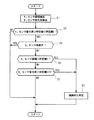
本発明の第1実施形態にかかる内燃機関の排気浄化装置は上述のように構成されているので、以下の条件が成立すると、図3に示すようなフローチャートに基づいて空燃比が制御される。まず、制御実行条件について説明すると、排気空燃比が振幅(パータベーション)していることが前提となる。パータベーションは、触媒6の上流側O2センサ又は下流側O2センサ3aの出力値をフィードバックしても良いし、O/L(オープンループ制御)で行なってもよい。
【0021】
そして、上記の条件が成立すると、ステップS1においてO2センサ3aからの情報によりO2センサ値の振幅及びO2センサ値の変化(変化率)が取り込まれる。
O2センサ値の振幅は、(O2センサ出力値の最大値−O2センサ出力値の最小値)として求めることができる。この振幅は1サイクル毎に求めても良いし、所定期間(又は所定サイクル間)の最大値あるいは平均値としてもよい。
【0022】
また、O2センサ値の変化は、所定期間(又は所定サイクル間)の変化量として求めてもよいし、あるいは、所定期間(又は所定サイクル間)の平均的なO2センサ値の変化量として求めてもよい。平均的なO2センサ値としては、例えばフィルタリングした値、又は移動平均した値を用いることができる。または、所定区間(所定期間×所定回数)の平均変化量としてもよい。
【0023】
さらには、O2センサ変化は下式により求めても良い。
【0024】
【数1】

【0025】
次に、ステップS2に進み、O2センサ出力値の変化が所定値1/所定値2(所定値1≧所定値2)よりも大きいか否かが判定される。この判定は、リーン運転以外の運転状態(w/oリーン)後、O2センサ値の変化が所定値1よりも大きくなって、その後所定値2以下となったか否かを判断するものであり、還元被毒可能な状態となったか否かを判定するものである。O2センサ出力値の変化が所定値1/所定値2よりも大きいと、還元被毒可能な状態となったとする。そして、還元被毒可能な状態が検出されなければ、それ以降の制御は実行されない。
【0026】
なお、上記の判定手法に代えて、O2センサ出力値>所定値(例えば、0.55V)か否かを判定してもよい。この場合、O2センサ出力値>所定値ならば還元被毒可能な状態(即ち、還元雰囲気)となったと判定する。
上記ステップS2でYESの場合、ステップS4に進み、O2センサ3aの感度が判定され、感度が高いと判定されるとリターンし、そうでなければステップS6に進む。
【0027】
ここで、例えばO2センサ出力値>所定値(例えばO.6V)であれば、感度が高いと判定される。これは、センサにもよるが、多くの場合、O2センサ出力値が所定値(例えばO.6V)以下では、空燃比に対するO2センサ出力値の変化量が上記所定値以上とでは大きく異なる〔すなわち、空燃比に対するO2センサ出力値の特性が線形ではなく所定値(例えば0.6V)近傍を境に異なる〕ことから、振幅値を同一レベルでは比較制御できないためである。
【0028】
なお、上記所定値は、O2センサ3aの劣化度合いに応じて補正してもよい。また、O2センサ3aの出力値に応じてO2センサ振幅を補正する場合〔例えば振幅=実振幅*補正係数(O2センサ出力のマップより設定される)〕、あるいは、ストイキオ近傍のO2センサ感度(出力vsA/F)特性が略均一の場合は、ステッブS4を省略しても良い。
【0029】
また、ステップS4からステップS6に進んだ場合には、O2センサ振幅が所定値3よりも大きいか否かが判定されて、所定値3よりも大きければステップS3に進んで触媒劣化判定が行なわれる。
また、O2センサ振幅が所定値3以下の場合には、ステップS6からステップS7に進み、O2センサ変化が正の所定値4よりも大きいか否かが判定される。ここで、O2センサ変化が所定値4よりも大きければ、やはりステップS3に進んで触媒劣化判定が行なわれる。
【0030】
また、O2センサ変化が所定値4以下の場合には、リターンする。
また、上記のステップS6,ステップS7は上記の順番に限定されるものではなく、適宜入れ替えてもよい。
また、ステップS2に直列に触媒温度(又は排気温度)の高温判定(触媒温度が所定温度以上であるかどうかの判定)を実行するようにすることでさらに精度が向上する。これは、触媒温度(触媒の活性度合)によって還元被毒レベルとO2センサ3aの出力値との関係も異なってくるためである。この時の触媒温度は、触媒温度センサ3bによって検出した値を基に求めればよい。
【0031】
以上詳述したように、本発明の第1実施形態にかかる内燃機関の排気浄化装置によれば、触媒6の上流の排気空燃比が周期的に変動している状態で触媒6の下流の排気空燃比が所定の還元雰囲気であるときのO2センサ3aの出力値の振幅は、触媒6の還元被毒レベルに対応していることに着目して、この振幅の大きさにより正確に触媒6の劣化を検出できるという利点がある。
【0032】
なお、上述の判定制御において、パータベーション時の燃焼空燃比(A/F)は、トルク差が生じないように設定してもよい。例えば、空燃比を矩形波でパータベーションする場合、第1A/F(リーン側)と第2A/F(リッチ側)とをトルク差が生じないように予め設定する。この場合、点火時期の変更等の制御を併用しても良い。
【0033】
また、このときの排気空燃比をAF1,AF2とし、AF1をリーン側,AF2をリッチ側とした場合、AF1−理論空燃比>理論空燃比−AF2となるように、すなわち、理論空燃比からの還元雰囲気化度合いよりも酸化雰囲気化度合いを大きくするのが好ましい。また、三角波でパータベーションする場合も同様である。
【0034】
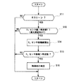
次に、本発明の第2実施形態にかかる内燃機関の排気浄化装置について説明すると、この第2実施形態は、上記第1実施形態に対して判定制御のステップの一部のみが異なっている。したがって、以下では、第1実施形態と異なる部分について着目して説明する。
図4に示すように、本第2実施形態では制御が簡略化されており、実質的には、第1実施形態のステップS7が省略されたものである。すなわち、ステッブS11でエンジンの運転状態がリーン運転時以外(w/oリーン)であると判定されると、ステップS12に進んで、O2センサ値が判定値1(例えば0.6V)よりも大きいか否かが判定される。このとき、判定値1よりも小さければリターンし、そうでなければ、ステップS14に進む。つまり、O2センサ出力値の大きさから還元被毒可能な状態(即ち、還元雰囲気)にあるか否かを判定しており、O2センサ出力値>所定値ならば還元被毒可能な状態(即ち、還元雰囲気)となったと判定し、ステップS14に進む。
【0035】
また、ステップS14に進むと、O2センサ3aの振幅値が算出される。このとき、振幅値はリアルタイム値を用いても良いし、平均的な値を用いてもよい。そして、ステップS15に進み、O2センサ振幅が所定値よりも大きいか否かが判定されて所定値よりも大きければ、ステップS16に進み触媒劣化と判定する。
【0036】
そして、このような構成により、本発明の第2実施形態にかかる内燃機関の排気浄化装置では、上述の第1実施形態と同様の作用効果を得ることができる。
なお、本発明の実施形態は、上述のものに限定されるものではなく、本発明の趣旨を逸脱しない範囲で種々の変形が可能である。
また、例えば、複数の触媒が排気系に設置されている場合には、各触媒のうち、触媒の下流に少なくとも1つ以上のO2センサを設けて本発明を適用すればよい。
【0037】
上記実施形態では、触媒上流のO2センサの検出値に基づいて空燃比をO2フィードバック制御して、排気空燃比を周期的に変動させているが、A/F強制変調制御等によりA/F制御する場合は触媒上流のO2センサを用いずに排気空燃比を周期的に変動させることもできる。この場合、触媒上流のO2センサを要しないで触媒の劣化判定を行うことのできる本装置のコスト上のメリットをより有効に発揮することができる。
【0038】
また、上記実施形態のように触媒の上流のO2センサを使用し空燃比をO2フィードバック制御して排気空燃比を周期的に変動させる場合でも、上流のO2センサは、触媒劣化検出に使用する必要はなく、排気空燃比を周期的に変動させるのに用いるだけなので、必要最低限の精度の先さでよく、より簡素化されたセンサを使用することができる。これによって、システムの簡素化とともにコスト低減にもつなげることができる。
【0039】
なお、触媒下流O2センサが2つ以上ある場合には、運転条件によって使用するO2センサを切り換えるようにしても良い。
また、本装置を適用しうる排気浄化触媒は、上記実施形態のような三元触媒だけでなく、吸蔵型NOX触媒にも適用することができる。
例えば、図5(a)に示すように、UCC(床下触媒)として、触媒ケース内に上流側から三元触媒6a,吸蔵型NOX触媒6b,三元触媒6cの順に設置された構成のものにおいて、上流側の三元触媒6a及び吸蔵型NOX触媒6bの劣化を判定するには、吸蔵型NOX触媒6bの直下流側(下流側の三元触媒6cよりも上流側)に触媒下流O2センサ3aを設置して、この触媒下流O2センサ3aの検出情報を利用して上記実施形態と同様に判定することができる。
【0040】
また、例えば、図5(b)に示すように、UCC(床下触媒)として、触媒ケース内に上流側から吸蔵型NOX触媒6b、三元触媒6cが設置されたものにおいて、吸蔵型NOX触媒6bの劣化を判定するには、吸蔵型NOX触媒6bの直下流側(下流側の三元触媒6cよりも上流側)に触媒下流O2センサ3aを設置すればよい。
【0041】
なお、吸蔵型NOX触媒のNOX吸蔵能力の劣化を検知するメカニズムは、次のようなものであると推定される。吸蔵型NOX触媒に把持している貴金属の劣化により酸化機能(三元機能)が劣化してくると、NOをNO2へ酸化する機能も劣化し、吸蔵型NOX触媒は吸蔵剤(バリウム,カリウム,ナトリウム等のアルカリ金属,アルカリ土類鋼)にNOXを吸蔵できなくなる。これは、吸蔵型NOX触媒はNOをNO2の形にしてから吸蔵剤に吸蔵するためである。そのため、上記実施形態と同様に三元触媒の三元機能(酸化機能)の劣化を検出する方法と同じ方法で、吸蔵型NOX触媒のNOX吸蔵能力の劣化を検出できる。
【0042】
さらに、図5(b)に示すように、このUCC(床下触媒)の上流側に、FCC(フロント触媒)6d又はMCC(エキマニ触媒)6eをそなえたものでは、触媒温度センサ3bをFCC(フロント触媒)6d又はMCC(エキマニ触媒)6eの上流側に設置してもよい。
また、例えば、図5(c)に示すように、UCC(床下触媒)として、触媒ケース内に上流側から三元触媒6c、三元触媒機能一体型吸蔵型NOX触媒6fをそなえたものにおいて、三元触媒6a及び三元触媒機能一体型吸蔵型NOX触媒6fの劣化を判定するには、三元触媒機能一体型吸蔵型NOX触媒6fの直下流側に触媒下流O2センサ3aを設置すればよい。
また、よリ確実に触媒の劣化を判定するために、一旦、還元被毒からの再生を行った後に、触媒の劣化判定を行うようにしてもよい。具体的には、第1実施形態においては、ステップS3の前に、まず排気空燃比をリーン方向に補正し、触媒の還元被毒からの再生を試みる。その後に、ステップS3において触媒劣化判定を行い、触媒劣化と判定されなければ再生により還元被毒は解消したということであり、還元被毒度合いはまだ大きくなく触媒劣化度合いは小さいと考え、そのままリターンヘ戻る。一方、ステップS3において触媒劣化と判定されれば、再生によっても還元被毒は解消しなかったということであり、還元被毒度合いは大きく確実に触媒劣化と判断できる。同様に、第2実施形態においては、ステップS16の前で、一旦、排気空燃比のリーン化補正を行った後に、触媒劣化判定を行えばよい。
【0043】
また、還元被毒の影響が大きい触媒の上流にさらに触媒が配置されている場合には、上流触媒として酸素ストレージ能力がない、もしくは弱い触媒を用い、下流の触媒に対しては酸素ストレージ能力を強化するように構成すると、排気センサの出力の振幅と還元被毒の相関がより強くなり、より好ましい。
【0044】
【発明の効果】
以上詳述したように、本発明の排気浄化触媒の劣化判定装置によれば、触媒上流の排気空燃比を周期的に変動させている状態で触媒下流の排気空燃比が所定の還元雰囲気であるときの排気センサ出力の振幅は、触媒の還元被毒レベルに対応していることに着目して、O2センサ等の排気センサを触媒の前後にそれぞれ必須とすることなく、低コストで簡素なシステムにより内燃機関の排気浄化触媒の劣化を検出することができるようになる利点がある。
【図面の簡単な説明】
【図1】本発明の第1実施形態にかかる内燃機関の全体構成を示す模式図である。
【図2】本発明を創案する過程で得られた排気系の特性を示す図である。
【図3】本発明の第1実施形態にかかる排気浄化触媒の劣化判定装置の作用を説明するフローチャートである。
【図4】本発明の第2実施形態にかかる排気浄化触媒の劣化判定装置の作用を説明するフローチャートである。
【図5】(a)〜(c)はいずれも本発明の適用しうる他の排気浄化触媒の配置構成を示す図である。
【符号の説明】
3 排気通路
3a 排気センサ
6,6a〜6f 排気浄化触媒
201 空燃比制御手段
202 触媒劣化判定手段[0001]
BACKGROUND OF THE INVENTION
The present invention relates to an exhaust purification catalyst deterioration determination device provided in an internal combustion engine.
[0002]
[Prior art]
Conventionally, a three-way catalyst is widely known as a system for purifying exhaust gas of an internal combustion engine. In such a three-way catalyst, along with the durability deterioration, NO X purification efficiency is deteriorated. Especially when FCC (front catalyst) and UCC (underfloor catalyst) are attached to the exhaust system, or when MCC (exhaust manifold catalyst) and UCC (underfloor catalyst) are attached to the exhaust system, NO X Deterioration of purification efficiency appears remarkably.
[0003]
By adjusting the average value of the air-fuel ratio (hereinafter referred to as average A / F), NO x , CO, and THC can all be in good purification performance, but the optimum A / F has a narrow allowable range. Since it varies depending on the deterioration state of the catalyst, it is difficult to obtain it in advance using a map or the like. For example, in a catalyst having a different deterioration state, the average A / F for purifying NO x most efficiently is also different.
[0004]
This is mainly due to the following reasons. That is, CO flows in a rich atmosphere, but since there is almost no oxygen, CO poisoning of the catalyst occurs and the catalyst performance deteriorates. CO poisoning occurs due to a delicate balance such as CO adsorption and CO desorption (or oxidation), and the CO poisoning state varies depending on the deterioration state of the catalyst.
In addition to CO poisoning, the NO x purification efficiency may be reduced due to the inactivation of the water gas reaction due to the inactivation of Ce (CeO 2 + CO → Ce 2 O 3 + CO 2 ) in addition to CO poisoning.
[0005]
CO + H 2 O → H 2 + CO 2
2NO + 2H 2 → N 2 + 2H 2 O
The deterioration of catalyst performance in these reducing atmospheres is hereinafter referred to as reducing poisoning.
In particular, in a lean-burn engines such as direct injection engines in gasoline tube, since the three-way catalyst during the lean operation to lower the NO X purification efficiency, greatly affected by deterioration of the NO X purification efficiency, reduction of the NO X emissions It is a challenge, because of the NO X emission reduction during the lean continuous rolling, for example attached by adding NO X catalyst such occlusion-type NO X catalyst in the three-way catalyst technology has been developed. Of course, such NO x catalyst also deteriorates in durability.
[0006]
Since the exhaust gas purification ability and the exhaust purification catalyst such as a three-way catalyst or occlusion-type NO X catalyst is deteriorated it is reduced, if the catalyst is deteriorated (once the exhaust purifying capability decreases) operated by the lighting of the engine check lamp It is necessary to warn the person and replace the catalyst. In order to properly manage the exhaust purification catalyst without waste, it is necessary to detect catalyst deterioration.
[0007]
As a conventional general method for detecting catalyst deterioration, there is known a method in which an O 2 sensor (oxygen concentration sensor) is mounted on each of the upstream side and the downstream side of the catalyst and the amplitude or frequency of the O 2 sensor is compared. It has been.
[0008]
[Problems to be solved by the invention]
However, the conventional general method for detecting catalyst deterioration as described above requires O 2 sensors on both the upstream side and the downstream side of the catalyst. When the air-fuel ratio is controlled by O 2 feedback, an O 2 sensor is provided on the upstream side of the catalyst. However, when A / F control is performed by A / F forced modulation control or the like, the O 2 sensor upstream of the catalyst is not necessary. In this case, it is necessary to provide a new O 2 sensor upstream of the catalyst only for detecting the catalyst deterioration, resulting in an increase in cost.
[0009]
Further, in the conventional general method as described above, since the upstream and downstream O 2 sensor signals are simultaneously compared and used, the upstream sensor has the same signal level as the downstream sensor, If the sensor is not accurate enough to detect the catalyst deterioration, there is a risk of erroneous determination.
The present invention has been devised in view of such problems, and it is possible to detect the deterioration of the exhaust purification catalyst of the internal combustion engine by a low-cost and simple system without requiring a plurality of exhaust sensors such as an O 2 sensor. An object of the present invention is to provide a deterioration determination device for an exhaust purification catalyst.
[0010]
[Means for Solving the Problems]
For this reason, in the exhaust purification catalyst deterioration determination device of the present invention, the exhaust air-fuel ratio upstream of the exhaust purification catalyst provided in the exhaust passage of the internal combustion engine is periodically changed by the air-fuel ratio control means, and is placed downstream of the catalyst. A state quantity correlated with the exhaust air-fuel ratio downstream of the catalyst is detected by an exhaust sensor provided, and the air-fuel ratio control means causes the exhaust air-fuel ratio downstream of the catalyst to become a reducing atmosphere by the catalyst deterioration determination means. in operating conditions that are periodically fluctuating exhaust air-fuel ratio of the upstream side, based on the output of the exhaust sensor is a predetermined reducing atmosphere exhaust air-fuel ratio of the catalyst downstream to allow reduction poisoning the catalyst Is determined so as to determine the deterioration state of the catalyst based on the amplitude of the output of the exhaust sensor. Thereby, it is possible to determine the deterioration of the catalyst by a low-cost and simple system without requiring a plurality of exhaust sensors.
It is preferable that the air-fuel ratio control means execute the periodic fluctuation of the upstream exhaust air-fuel ratio by either open loop control or feedback control based on the output of the exhaust sensor.
The catalyst deterioration determination means sets the catalyst in a state capable of reducing poisoning depending on whether the change in the output value of the exhaust sensor is a predetermined value or more, or whether the output value of the exhaust sensor is a predetermined value or more. It is preferable to determine whether or not the exhaust air-fuel ratio downstream of the catalyst is a predetermined reducing atmosphere when the catalyst is in a state capable of reducing poisoning.
[0011]
DETAILED DESCRIPTION OF THE INVENTION
Hereinafter, embodiments of the present invention will be described with reference to the drawings.
First, an exhaust purification catalyst deterioration determination apparatus according to the first embodiment will be described.
As shown in FIG. 1, this apparatus is applied here to a direct injection internal combustion engine. The cylinder injection type internal combustion engine will be briefly described. An intake passage 2 is connected to the
[0012]
The intake passage 2 includes an
[0013]
An
[0014]
In addition to the above-described
[0015]
Here, in the cylinder injection engine, the intake air is generated as a longitudinal vortex flow (reverse tumble flow) in the
[0016]
Such an operation mode is selected by the
[0017]
Next, the configuration of the main part of the apparatus will be described.
The
[0018]
The
Here, FIG. 2 is a diagram showing the output value of the O 2 sensor 3a and the exhaust air-fuel ratio downstream of the catalyst when the
[0019]
Also from this figure, the degree of reduction poisoning ( CO poisoning) of the catalyst 6 (that is, the degree of catalyst deterioration: the catalyst deterioration level) corresponds to the O 2 sensor value downstream of the catalyst or the exhaust air-fuel ratio. I understand that.
The present invention focuses on these points. That is, an operating state in which the exhaust air-fuel ratio upstream of the
[0020]
The air-fuel ratio control means 201 is based on the outputs of an exhaust sensor (not shown O 2 sensor described above) that detects a state quantity correlated with the exhaust air-fuel ratio upstream of the catalyst and the O 2 sensor 3 a provided downstream of the catalyst. Then, the air-fuel ratio may be feedback controlled in the vicinity of stoichiometric.
Since the exhaust gas purification apparatus for an internal combustion engine according to the first embodiment of the present invention is configured as described above, the air-fuel ratio is controlled based on the flowchart shown in FIG. 3 when the following conditions are satisfied. First, the control execution condition will be described based on the premise that the exhaust air-fuel ratio has an amplitude (perturbation). The perturbation may be performed by feeding back the output value of the upstream O 2 sensor or the downstream O 2 sensor 3a of the
[0021]
When the above conditions are satisfied, changes in amplitude and O 2 sensor value of the O 2 sensor value based on information from the O 2 sensor 3a (rate of change) is taken in step S1.
The amplitude of the O 2 sensor value can be determined as (O 2 minimum value for the maximum value -O 2 sensor output value of the sensor output value). This amplitude may be obtained every cycle, or may be a maximum value or an average value during a predetermined period (or between predetermined cycles).
[0022]
The change of the O 2 sensor value may be calculated as a change amount of a predetermined time period (or between a predetermined cycle), or between the predetermined period (or a predetermined cycle to cycle) average variation of the O 2 sensor value You may ask as. As the average O 2 sensor value, for example, a filtered value or a moving average value can be used. Or it is good also as an average variation | change_quantity of a predetermined area (predetermined period x predetermined number of times).
[0023]
Furthermore, the O 2 sensor change may be obtained by the following equation.
[0024]
[Expression 1]
[0025]
Next, the process proceeds to step S2, and it is determined whether or not the change in the O 2 sensor output value is larger than a
[0026]
Instead of the determination method described above, it may be determined whether or not O 2 sensor output value> predetermined value (for example, 0.55 V). In this case, if the O 2 sensor output value> predetermined value, it is determined that the reduction poisoning is possible (that is, a reducing atmosphere).
If YES in step S2, the process proceeds to step S4, where the sensitivity of the O 2 sensor 3a is determined. If it is determined that the sensitivity is high, the process returns; otherwise, the process proceeds to step S6.
[0027]
Here, for example, if O 2 sensor output value> predetermined value (eg, O.6V), it is determined that the sensitivity is high. Although this depends on the sensor, in many cases, when the O 2 sensor output value is a predetermined value (for example, O.6 V) or less, the change amount of the O 2 sensor output value with respect to the air-fuel ratio is greatly different from the predetermined value or more. [In other words, the characteristic of the O 2 sensor output value with respect to the air-fuel ratio is not linear but differs around a predetermined value (for example, 0.6 V), and therefore, the amplitude value cannot be compared and controlled at the same level.
[0028]
The predetermined value may be corrected according to the degree of deterioration of the O 2 sensor 3a. Further, when the O 2 sensor amplitude is corrected according to the output value of the O 2 sensor 3a [for example, amplitude = actual amplitude * correction coefficient (set from the O 2 sensor output map)], or O 2 in the vicinity of stoichio. If the sensor sensitivity (output vs. A / F) characteristic is substantially uniform, step S4 may be omitted.
[0029]
Further, when the process proceeds from step S4 to step S6, it is determined whether or not the O 2 sensor amplitude is larger than a
On the other hand, when the O 2 sensor amplitude is equal to or smaller than the
[0030]
If the O 2 sensor change is less than or equal to the predetermined value 4, the process returns.
Moreover, said step S6 and step S7 are not limited to said order, You may replace suitably.
Further, the accuracy is further improved by performing a high temperature determination (determination as to whether the catalyst temperature is equal to or higher than the predetermined temperature) of the catalyst temperature (or exhaust temperature) in series with step S2. This is because the relationship between the reduction poisoning level and the output value of the O 2 sensor 3a varies depending on the catalyst temperature (the degree of activity of the catalyst). The catalyst temperature at this time may be obtained based on the value detected by the
[0031]
As described above in detail, according to the exhaust gas purification apparatus for an internal combustion engine according to the first embodiment of the present invention, the exhaust gas downstream of the
[0032]
In the determination control described above, the combustion air-fuel ratio (A / F) at the time of perturbation may be set so as not to cause a torque difference. For example, when perturbing the air-fuel ratio with a rectangular wave, the first A / F (lean side) and the second A / F (rich side) are set in advance so as not to cause a torque difference. In this case, control such as changing the ignition timing may be used in combination.
[0033]
Further, when the exhaust air-fuel ratio at this time is AF1, AF2, AF1 is on the lean side, and AF2 is on the rich side, AF1-theoretical air-fuel ratio> theoretical air-fuel ratio-AF2, that is, from the stoichiometric air-fuel ratio. It is preferable to make the degree of oxidizing atmosphere greater than the degree of reducing atmosphere. The same applies to the case of perturbation with a triangular wave.
[0034]
Next, an exhaust emission control device for an internal combustion engine according to a second embodiment of the present invention will be described. The second embodiment differs from the first embodiment only in part of the determination control step. Accordingly, the following description will be focused on differences from the first embodiment.
As shown in FIG. 4, control is simplified in the second embodiment, and step S7 of the first embodiment is substantially omitted. That is, if it is determined in step S11 that the engine operating state is other than the lean operation (w / o lean), the process proceeds to step S12, and the O 2 sensor value is higher than the determination value 1 (eg, 0.6 V). It is determined whether it is larger. At this time, if it is smaller than the
[0035]
In step S14, the amplitude value of the O 2 sensor 3a is calculated. At this time, the amplitude value may be a real-time value or an average value. Then, the process proceeds to step S15, where it is determined whether or not the O 2 sensor amplitude is greater than a predetermined value, and if it is greater than the predetermined value, the process proceeds to step S16 and it is determined that the catalyst has deteriorated.
[0036]
With such a configuration, the exhaust gas purification apparatus for an internal combustion engine according to the second embodiment of the present invention can obtain the same effects as those of the first embodiment described above.
The embodiment of the present invention is not limited to the above-described embodiment, and various modifications can be made without departing from the spirit of the present invention.
In addition, for example, when a plurality of catalysts are installed in the exhaust system, the present invention may be applied by providing at least one O 2 sensor downstream of the catalyst among the catalysts.
[0037]
In the above embodiment, the air-fuel ratio is O 2 feedback controlled based on the detection value of the O 2 sensor upstream of the catalyst, and the exhaust air-fuel ratio is periodically changed. In the case of F control, the exhaust air-fuel ratio can be periodically changed without using the O 2 sensor upstream of the catalyst. In this case, it is possible to more effectively exhibit the cost advantage of the present apparatus that can determine the deterioration of the catalyst without requiring an O 2 sensor upstream of the catalyst.
[0038]
Further, even when the air-fuel ratio using the O 2 sensor upstream of the catalyst with O 2 feedback control to vary the exhaust air-fuel ratio periodically as in the above embodiment, the upstream O 2 sensor is in the catalyst deterioration detection It is not necessary to use it, and it is only used for periodically changing the exhaust air-fuel ratio. Therefore, it is sufficient to use the tip with the minimum accuracy, and a more simplified sensor can be used. This can lead to simplification of the system and cost reduction.
[0039]
If there are two or more catalyst downstream O 2 sensors, the O 2 sensor to be used may be switched depending on the operating conditions.
The exhaust gas purifying catalyst that can be applied to this device, not only the three-way catalyst as in the above embodiment can be applied to the occlusion-type NO X catalyst.
For example, as shown in FIG. 5 (a), as UCC (underfloor catalyst), those from the upstream side in the catalyst case the three-
[0040]
Further, for example, as shown in FIG. 5 (b), as the UCC (underfloor catalyst), occlusion-type NO X
[0041]
Incidentally, the mechanism for detecting the deterioration of the NO X storage capability of the occlusion-type NO X catalyst is estimated to be as follows. When oxidation function by degradation of the noble metal that is grasped occlusion-type NO X catalyst (three-way function) deteriorates, the ability to oxidize NO to NO 2 is also deteriorated, occlusion-type NO X catalyst storage agent (barium , potassium, can not absorb NO X in the alkali metal, alkaline earth steel) such as sodium. This is because the storage-type NO x catalyst stores NO in the storage agent after making NO into the NO 2 form. Therefore, in the same manner as the method of detecting the deterioration of the three-way function of the three-way catalyst in the same manner as the above embodiment (oxidation function), it can detect the deterioration of the NO X storage capability of the occlusion-type NO X catalyst.
[0042]
Further, as shown in FIG. 5B, in the case where an FCC (front catalyst) 6d or MCC (exhaust manifold catalyst) 6e is provided upstream of the UCC (underfloor catalyst), the
Further, for example, as shown in FIG. 5 (c), as UCC (underfloor catalyst), the three-
Further, in order to more reliably determine the deterioration of the catalyst, the deterioration of the catalyst may be determined after regenerating from the reduction poisoning. Specifically, in the first embodiment, before step S3, first, the exhaust air-fuel ratio is corrected in the lean direction, and regeneration from the reduction poisoning of the catalyst is attempted. After that, in step S3, the catalyst deterioration is determined. If it is not determined that the catalyst is deteriorated, it means that the reduction poisoning has been eliminated by regeneration. The reduction poisoning degree is still not large and the catalyst deterioration degree is small. Return. On the other hand, if it is determined in step S3 that the catalyst has deteriorated, it means that the reduction poisoning has not been eliminated by the regeneration, and the degree of reduction poisoning can be determined to be large and surely the catalyst deterioration. Similarly, in the second embodiment, the catalyst deterioration determination may be performed after the lean air-fuel ratio correction is once performed before step S16.
[0043]
In addition, when a catalyst is further arranged upstream of a catalyst that is greatly affected by reduction poisoning, an oxygen storage capacity is not used as the upstream catalyst or a weak catalyst is used, and an oxygen storage capacity is not provided for the downstream catalyst. If it is configured so as to strengthen, the correlation between the amplitude of the exhaust sensor output and the reduction poisoning becomes stronger, which is more preferable.
[0044]
【The invention's effect】
As described above in detail, according to the exhaust purification catalyst deterioration determination device of the present invention, the exhaust air-fuel ratio downstream of the catalyst is in a predetermined reducing atmosphere while the exhaust air-fuel ratio upstream of the catalyst is periodically varied. Focusing on the fact that the amplitude of the exhaust sensor output corresponds to the reduction poisoning level of the catalyst, the exhaust sensor such as an O 2 sensor is not necessary before and after the catalyst, and is simple and low-cost. There is an advantage that the deterioration of the exhaust purification catalyst of the internal combustion engine can be detected by the system.
[Brief description of the drawings]
FIG. 1 is a schematic diagram showing an overall configuration of an internal combustion engine according to a first embodiment of the present invention.
FIG. 2 is a diagram showing the characteristics of an exhaust system obtained in the process of creating the present invention.
FIG. 3 is a flowchart for explaining the operation of the exhaust gas purification catalyst deterioration determination device according to the first embodiment of the present invention.
FIG. 4 is a flowchart for explaining the operation of an exhaust purification catalyst deterioration determination device according to a second embodiment of the present invention.
FIGS. 5A to 5C are diagrams showing the arrangement of other exhaust purification catalysts to which the present invention can be applied.
[Explanation of symbols]
3
Claims (3)
上記排気浄化触媒の上流側の排気空燃比を周期的に変動させる空燃比制御手段と、
上記触媒下流の排気空燃比に相関する状態量を検出する排気センサと、
上記空燃比制御手段が、上記触媒下流の排気空燃比が還元雰囲気となるように上記上流側の排気空燃比を周期的に変動させている運転状態において、上記排気センサの出力に基づき、上記触媒下流の排気空燃比が上記触媒を還元被毒可能とする所定の還元雰囲気であると判定される時に上記排気センサの出力の振幅の大きさにより上記触媒の劣化状態を判定する触媒劣化判定手段と
を備えたことを特徴とする、排気浄化触媒の劣化判定装置。An exhaust purification catalyst provided in the exhaust passage of the internal combustion engine;
Air-fuel ratio control means for periodically varying the exhaust air-fuel ratio upstream of the exhaust purification catalyst;
An exhaust sensor for detecting a state quantity correlated with the exhaust air-fuel ratio downstream of the catalyst;
The air-fuel ratio control means, in the operating state the exhaust air-fuel ratio of the catalyst downstream is periodically varying the exhaust air-fuel ratio of the upstream side so that the reducing atmosphere, based on the output of the exhaust sensor, the catalyst Catalyst deterioration determination means for determining the deterioration state of the catalyst based on the amplitude of the output of the exhaust sensor when it is determined that the downstream exhaust air-fuel ratio is a predetermined reducing atmosphere that enables the catalyst to be reduced and poisoned ; An exhaust purification catalyst deterioration determination device comprising:
ことを特徴とする、請求項1記載の排気浄化触媒の劣化判定装置。The air-fuel ratio control means executes the periodic fluctuation of the upstream exhaust air-fuel ratio by either open loop control or feedback control based on the output of the exhaust sensor. Item 2. An exhaust purification catalyst deterioration judging device according to Item 1.
ことを特徴とする、請求項1又は2記載の排気浄化触媒の劣化判定装置。The catalyst deterioration determination means sets the catalyst in a state capable of reducing poisoning depending on whether the change in the output value of the exhaust sensor is a predetermined value or more, or whether the output value of the exhaust sensor is a predetermined value or more. The exhaust gas purification according to claim 1 or 2, wherein it is determined whether or not the catalyst is in a state where the catalyst can be reduced and poisoned, and the exhaust air-fuel ratio downstream of the catalyst is determined to be a predetermined reducing atmosphere. Catalyst deterioration judgment device.
Priority Applications (1)
| Application Number | Priority Date | Filing Date | Title |
|---|---|---|---|
| JP2001112481A JP4635365B2 (en) | 2001-04-11 | 2001-04-11 | Exhaust purification catalyst deterioration judgment device |
Applications Claiming Priority (1)
| Application Number | Priority Date | Filing Date | Title |
|---|---|---|---|
| JP2001112481A JP4635365B2 (en) | 2001-04-11 | 2001-04-11 | Exhaust purification catalyst deterioration judgment device |
Publications (2)
| Publication Number | Publication Date |
|---|---|
| JP2002309927A JP2002309927A (en) | 2002-10-23 |
| JP4635365B2 true JP4635365B2 (en) | 2011-02-23 |
Family
ID=18963888
Family Applications (1)
| Application Number | Title | Priority Date | Filing Date |
|---|---|---|---|
| JP2001112481A Expired - Fee Related JP4635365B2 (en) | 2001-04-11 | 2001-04-11 | Exhaust purification catalyst deterioration judgment device |
Country Status (1)
| Country | Link |
|---|---|
| JP (1) | JP4635365B2 (en) |
Families Citing this family (3)
| Publication number | Priority date | Publication date | Assignee | Title |
|---|---|---|---|---|
| JP2008128604A (en) | 2006-11-24 | 2008-06-05 | Sanyo Electric Co Ltd | Electric storage type air conditioning system, operation method and control program for electric storage type air conditioning system |
| JP4872005B2 (en) * | 2010-01-19 | 2012-02-08 | 本田技研工業株式会社 | Exhaust gas sensor deterioration diagnosis device |
| JP2012162994A (en) * | 2011-02-03 | 2012-08-30 | Toyota Motor Corp | System for determining deterioration of exhaust emission control device |
Family Cites Families (8)
| Publication number | Priority date | Publication date | Assignee | Title |
|---|---|---|---|---|
| JP2666532B2 (en) * | 1990-07-30 | 1997-10-22 | トヨタ自動車株式会社 | Air-fuel ratio control device for internal combustion engine |
| JP2503829B2 (en) * | 1991-04-23 | 1996-06-05 | トヨタ自動車株式会社 | Air-fuel ratio control device for internal combustion engine |
| FR2682993B1 (en) * | 1991-10-28 | 1994-01-28 | Siemens Automotive Sa | METHOD FOR MONITORING THE EFFICIENCY OF A CATALYTIC EXHAUST TREATMENT POT OF AN INTERNAL COMBUSTION ENGINE. |
| JP3147866B2 (en) * | 1994-05-06 | 2001-03-19 | 日産自動車株式会社 | Engine catalyst deterioration diagnosis device |
| JP3292019B2 (en) * | 1995-10-03 | 2002-06-17 | トヨタ自動車株式会社 | Catalyst deterioration determination device for internal combustion engine |
| JPH09203314A (en) * | 1996-01-25 | 1997-08-05 | Nissan Motor Co Ltd | Engine exhaust purification device |
| JP3651159B2 (en) * | 1997-01-30 | 2005-05-25 | 日産自動車株式会社 | Engine catalyst deterioration diagnosis device and air-fuel ratio control device |
| JP2001050086A (en) * | 1999-08-09 | 2001-02-23 | Denso Corp | Air-fuel ratio control unit for internal combustion engine |
-
2001
- 2001-04-11 JP JP2001112481A patent/JP4635365B2/en not_active Expired - Fee Related
Also Published As
| Publication number | Publication date |
|---|---|
| JP2002309927A (en) | 2002-10-23 |
Similar Documents
| Publication | Publication Date | Title |
|---|---|---|
| US9021789B2 (en) | Degradation diagnostic apparatus for NOx catalyst | |
| JP4537417B2 (en) | NOx sensor abnormality diagnosis device | |
| JP4485553B2 (en) | NOx sensor abnormality diagnosis device | |
| JP4737010B2 (en) | Catalyst deterioration diagnosis device | |
| JP5062529B2 (en) | Apparatus and method for diagnosing catalyst degradation | |
| WO2011132232A1 (en) | Catalyst anomaly diagnostic system | |
| CN101501309B (en) | Catalyst monitoring system and method | |
| US6484493B2 (en) | Exhaust emission control device for internal combustion engine | |
| US6467256B2 (en) | Exhaust emission control system for internal combustion engine | |
| JP5229628B2 (en) | Catalyst deterioration diagnosis device | |
| JP5212826B2 (en) | Catalyst abnormality diagnosis device | |
| JP2009127597A (en) | Catalyst deterioration diagnosis device | |
| JP2009036172A (en) | Catalyst deterioration diagnosis device for internal combustion engine | |
| JP4635365B2 (en) | Exhaust purification catalyst deterioration judgment device | |
| JP2008031901A (en) | Catalyst deterioration detection device for internal combustion engine | |
| JP2009150367A (en) | Catalyst deterioration diagnosis device for internal combustion engine | |
| JP4411755B2 (en) | Exhaust purification catalyst deterioration state diagnosis device | |
| JP2009215924A (en) | Fuel property determination device and catalyst deterioration diagnostic device having the same | |
| JP2006316752A (en) | Catalyst deterioration judgment device | |
| JP3867192B2 (en) | Exhaust gas purification device for internal combustion engine | |
| JP5088632B2 (en) | Catalyst deterioration diagnosis device | |
| JP4061478B2 (en) | Exhaust gas purification device for internal combustion engine | |
| JP2009191786A (en) | Fuel property determination device | |
| JP2021102943A (en) | Catalyst deterioration detection device | |
| JP2007198251A (en) | Catalyst degradation detector |
Legal Events
| Date | Code | Title | Description |
|---|---|---|---|
| A621 | Written request for application examination |
Free format text: JAPANESE INTERMEDIATE CODE: A621 Effective date: 20071219 |
|
| A977 | Report on retrieval |
Free format text: JAPANESE INTERMEDIATE CODE: A971007 Effective date: 20100204 |
|
| A131 | Notification of reasons for refusal |
Free format text: JAPANESE INTERMEDIATE CODE: A131 Effective date: 20100209 |
|
| A521 | Request for written amendment filed |
Free format text: JAPANESE INTERMEDIATE CODE: A523 Effective date: 20100409 |
|
| A131 | Notification of reasons for refusal |
Free format text: JAPANESE INTERMEDIATE CODE: A131 Effective date: 20100803 |
|
| A521 | Request for written amendment filed |
Free format text: JAPANESE INTERMEDIATE CODE: A523 Effective date: 20101004 |
|
| TRDD | Decision of grant or rejection written | ||
| A01 | Written decision to grant a patent or to grant a registration (utility model) |
Free format text: JAPANESE INTERMEDIATE CODE: A01 Effective date: 20101026 |
|
| A01 | Written decision to grant a patent or to grant a registration (utility model) |
Free format text: JAPANESE INTERMEDIATE CODE: A01 |
|
| A61 | First payment of annual fees (during grant procedure) |
Free format text: JAPANESE INTERMEDIATE CODE: A61 Effective date: 20101108 |
|
| FPAY | Renewal fee payment (event date is renewal date of database) |
Free format text: PAYMENT UNTIL: 20131203 Year of fee payment: 3 |
|
| R151 | Written notification of patent or utility model registration |
Ref document number: 4635365 Country of ref document: JP Free format text: JAPANESE INTERMEDIATE CODE: R151 |
|
| FPAY | Renewal fee payment (event date is renewal date of database) |
Free format text: PAYMENT UNTIL: 20131203 Year of fee payment: 3 |
|
| LAPS | Cancellation because of no payment of annual fees |