JP4635263B2 - Headlight irradiation angle control system - Google Patents
Headlight irradiation angle control system Download PDFInfo
- Publication number
- JP4635263B2 JP4635263B2 JP2007010696A JP2007010696A JP4635263B2 JP 4635263 B2 JP4635263 B2 JP 4635263B2 JP 2007010696 A JP2007010696 A JP 2007010696A JP 2007010696 A JP2007010696 A JP 2007010696A JP 4635263 B2 JP4635263 B2 JP 4635263B2
- Authority
- JP
- Japan
- Prior art keywords
- curve
- information
- headlamp
- irradiation angle
- host vehicle
- Prior art date
- Legal status (The legal status is an assumption and is not a legal conclusion. Google has not performed a legal analysis and makes no representation as to the accuracy of the status listed.)
- Expired - Fee Related
Links
Images


Classifications
-
- B—PERFORMING OPERATIONS; TRANSPORTING
- B60—VEHICLES IN GENERAL
- B60Q—ARRANGEMENT OF SIGNALLING OR LIGHTING DEVICES, THE MOUNTING OR SUPPORTING THEREOF OR CIRCUITS THEREFOR, FOR VEHICLES IN GENERAL
- B60Q1/00—Arrangement of optical signalling or lighting devices, the mounting or supporting thereof or circuits therefor
- B60Q1/02—Arrangement of optical signalling or lighting devices, the mounting or supporting thereof or circuits therefor the devices being primarily intended to illuminate the way ahead or to illuminate other areas of way or environments
- B60Q1/04—Arrangement of optical signalling or lighting devices, the mounting or supporting thereof or circuits therefor the devices being primarily intended to illuminate the way ahead or to illuminate other areas of way or environments the devices being headlights
- B60Q1/06—Arrangement of optical signalling or lighting devices, the mounting or supporting thereof or circuits therefor the devices being primarily intended to illuminate the way ahead or to illuminate other areas of way or environments the devices being headlights adjustable, e.g. remotely-controlled from inside vehicle
- B60Q1/08—Arrangement of optical signalling or lighting devices, the mounting or supporting thereof or circuits therefor the devices being primarily intended to illuminate the way ahead or to illuminate other areas of way or environments the devices being headlights adjustable, e.g. remotely-controlled from inside vehicle automatically
- B60Q1/12—Arrangement of optical signalling or lighting devices, the mounting or supporting thereof or circuits therefor the devices being primarily intended to illuminate the way ahead or to illuminate other areas of way or environments the devices being headlights adjustable, e.g. remotely-controlled from inside vehicle automatically due to steering position
-
- B—PERFORMING OPERATIONS; TRANSPORTING
- B60—VEHICLES IN GENERAL
- B60Q—ARRANGEMENT OF SIGNALLING OR LIGHTING DEVICES, THE MOUNTING OR SUPPORTING THEREOF OR CIRCUITS THEREFOR, FOR VEHICLES IN GENERAL
- B60Q2300/00—Indexing codes for automatically adjustable headlamps or automatically dimmable headlamps
- B60Q2300/10—Indexing codes relating to particular vehicle conditions
- B60Q2300/11—Linear movements of the vehicle
- B60Q2300/112—Vehicle speed
-
- B—PERFORMING OPERATIONS; TRANSPORTING
- B60—VEHICLES IN GENERAL
- B60Q—ARRANGEMENT OF SIGNALLING OR LIGHTING DEVICES, THE MOUNTING OR SUPPORTING THEREOF OR CIRCUITS THEREFOR, FOR VEHICLES IN GENERAL
- B60Q2300/00—Indexing codes for automatically adjustable headlamps or automatically dimmable headlamps
- B60Q2300/10—Indexing codes relating to particular vehicle conditions
- B60Q2300/11—Linear movements of the vehicle
- B60Q2300/114—Vehicle acceleration or deceleration
-
- B—PERFORMING OPERATIONS; TRANSPORTING
- B60—VEHICLES IN GENERAL
- B60Q—ARRANGEMENT OF SIGNALLING OR LIGHTING DEVICES, THE MOUNTING OR SUPPORTING THEREOF OR CIRCUITS THEREFOR, FOR VEHICLES IN GENERAL
- B60Q2300/00—Indexing codes for automatically adjustable headlamps or automatically dimmable headlamps
- B60Q2300/30—Indexing codes relating to the vehicle environment
- B60Q2300/32—Road surface or travel path
- B60Q2300/322—Road curvature
-
- B—PERFORMING OPERATIONS; TRANSPORTING
- B60—VEHICLES IN GENERAL
- B60Q—ARRANGEMENT OF SIGNALLING OR LIGHTING DEVICES, THE MOUNTING OR SUPPORTING THEREOF OR CIRCUITS THEREFOR, FOR VEHICLES IN GENERAL
- B60Q2300/00—Indexing codes for automatically adjustable headlamps or automatically dimmable headlamps
- B60Q2300/30—Indexing codes relating to the vehicle environment
- B60Q2300/33—Driving situation
- B60Q2300/331—Driving situation characterised by the driving side, e.g. on the left or right hand side
Landscapes
- Engineering & Computer Science (AREA)
- Mechanical Engineering (AREA)
- Lighting Device Outwards From Vehicle And Optical Signal (AREA)
Description
本発明は、車両に配設される前照灯の照射角度を制御する前照灯照射角度制御システムに関する。 The present invention relates to a headlamp illumination angle control system that controls the illumination angle of a headlamp disposed in a vehicle.
この種の技術としては従来、例えば特許文献1に記載の技術が知られている。この文献に記載された技術では、自車両の車輪速を検出する車輪速センサによって検出される車輪速と、自車両のステアリングホイールの操舵角を検出する操舵角センサによって検出される操舵角とに基づき、所定時間経過後に自車両が到達すると予測される到達地点が、自車両の前照灯によって照射される照射範囲内に収まるように、前照灯の照射角度を制御している。
しかしながら、上述した前照灯照射角度制御システムでは、所定時間経過後に自車両が到達すると予測される到達地点が照射範囲に収まるように前照灯の照射角度を制御するとはいえ、車輪速や操舵角に基づいて前照灯の照射角度を決定していることから、前照灯の照射角度の制御が実際に開始される時期は、自車両が実際にカーブに入る直前、すなわち、自車両がカーブの開始点に極めて近い位置に到達して以後となってしまう。通常、車両を運転する運転者は、自車両のハンドルを操舵する前に、すなわち、自車両が実際にカーブに入る手前で、そのカーブの深さやカーブのきつさ等を予め視認している。したがって、例えば夜間に車両を運転する場合、自車両が実際にカーブに入る手前で、そのカーブの深さやカーブのきつさ等を予め視認しようとしても、前照灯によってそのカーブがまだ照らされていないため、自車両が進入するカーブの線型を自車両の運転者が予め視認しておくことは難しい。 However, in the above-described headlamp illumination angle control system, although the illumination angle of the headlamp is controlled so that the arrival point where the host vehicle is expected to reach after a predetermined time has passed is within the illumination range, the wheel speed and steering Since the lighting angle of the headlamp is determined based on the angle, the time when the control of the lighting angle of the headlamp is actually started is immediately before the own vehicle actually enters the curve, that is, the own vehicle After reaching a position very close to the starting point of the curve. Usually, the driver who drives the vehicle visually recognizes the depth of the curve, the tightness of the curve, and the like in advance before steering the steering wheel of the own vehicle, that is, before the own vehicle actually enters the curve. Therefore, for example, when driving a vehicle at night, even if you try to visually check the depth of the curve or the tightness of the curve before the vehicle actually enters the curve, the curve is still illuminated by the headlamps. For this reason, it is difficult for the driver of the host vehicle to visually recognize the linear shape of the curve into which the host vehicle enters.
本発明は、こうした実情を鑑みてなされたものであって、その目的は、自車両の運転者が当該自車両の進入するカーブの線型を予めより的確に視認することのできる前照灯照射角度制御システムを提供することにある。 The present invention has been made in view of such circumstances, and the purpose thereof is a headlight irradiation angle at which the driver of the host vehicle can accurately and accurately visually recognize the linear shape of the curve into which the host vehicle enters. To provide a control system.
こうした目的を達成するため、請求項1に記載の発明では、車両に配設される前照灯の照射角度を制御する前照灯照射角度制御システムであって、自車両の現在地を検出する自車両検出手段と、道路情報を記憶保持する記憶保持手段と、前記自車両の現在地及び前記道路情報に基づいて、自車両が進入するカーブの半径を取得する半径情報取得手段と、前記自車両の現在地及び前記道路情報に基づいて、自車両の現在地から前記カーブの開始点までの距離情報を取得する距離情報取得手段と、前記カーブが、異なる方向へ連続して曲がる線型を有するS字カーブであるか否かを前記道路情報に基づいて判定するとともに、その判定結果である線型情報を取得する線型情報取得手段と、前記カーブ半径、前記距離情報、及び前記線型情報に基づいて、前記前照灯の照射角度を算出する照射角度算出部と、前記照射角度算出部にて算出された照射角度に前記前照灯を制御する照射角度制御部とを備え、前記線型情報取得手段は、前記カーブがS字カーブであると判定するとき、前記線型情報Cとして「1」を出力するとともに、前記カーブがS字カーブでないと判定するとき、前記線型情報Cとして「0」を出力し、前記距離情報取得手段は、前記カーブの開始点を基準として、自車両の現在地から前記カーブの開始点までの距離情報L[m]を取得し、前記照射角度算出部は、カーブ半径R[m]、距離情報L[m]、及び線型情報Cを独立変数として、これら独立変数がそれぞれ所定係数β1〜δ1にて重み付けされるとともに、定数α1を含めた下式(8)に基づいて、自車両前方を基準とするスイブル角度θ[度]を前記前照灯の照射角度として算出し、前記照射角度制御部は、前記照射角度算出部にて算出されたスイブル角度θに前記前照灯を制御する前照灯照射角度制御システムにおいて、前記カーブがS字カーブであると判定されるとき、前記カーブがS字カーブでないと判定されるときに比べて、前記前照灯の照射方向を当該自車両の前方正面に近づけるべく、前記スイブル角度θの絶対値の大きさが小さくなるように、前記係数及び定数が定められていることを特徴とする。
また、請求項5に記載の発明では、車両に配設される前照灯の照射角度を制御する前照灯照射角度制御システムであって、自車両の現在地を検出する自車両検出手段と、道路情報を記憶保持する記憶保持手段と、前記自車両の現在地及び前記道路情報に基づいて、自車両が進入するカーブの半径を取得する半径情報取得手段と、前記自車両の現在地及び前記道路情報に基づいて、自車両の現在地から前記カーブの開始点までの距離情報を取得する距離情報取得手段と、前記カーブが、異なる方向へ連続して曲がる線型を有するS字カーブであるか否かを前記道路情報に基づいて判定するとともに、その判定結果である線型情報を取得する線型情報取得手段と、前記カーブ半径、前記距離情報、及び前記線型情報に基づいて、前記前照灯の照射角度を算出する照射角度算出部と、前記照射角度算出部にて算出された照射角度に前記前照灯を制御する照射角度制御部とを備え、前記線型情報取得手段は、前記カーブがS字カーブであると判定するとき、前記線型情報Cとして「1」を出力するとともに、前記カーブがS字カーブでないと判定するとき、前記線型情報Cとして「0」を出力し、前記距離情報取得手段は、前記カーブの開始点を基準として、自車両の現在地から前記カーブの開始点までの距離情報L[m]を取得し、前記照射角度算出部は、カーブ半径R[m]、距離情報L[m]、及び線型情報Cを独立変数として、これら独立変数がそれぞれ所定係数β1〜δ1にて重み付けされるとともに、定数α1を含めた下式(8)に基づいて、自車両前方を基準とするスイブル角度θ[度]を前記前照灯の照射角度として算出し、前記照射角度制御部は、前記照射角度算出部にて算出されたスイブル角度θに前記前照灯を制御する前照灯照射角度制御システムにおいて、前記カーブの半径が大きくなるほど、前記前照灯の照射方向を当該自車両の前方正面に近づけるべく、前記スイブル角度の絶対値の大きさが小さくなるように、前記係数及び定数が定められていることを特徴とする。
また、請求項11に記載の発明では、車両に配設される前照灯の照射角度を制御する前照灯照射角度制御システムであって、自車両の現在地を検出する自車両検出手段と、道路情報を記憶保持する記憶保持手段と、前記自車両の現在地及び前記道路情報に基づいて、自車両が進入するカーブの半径を取得する半径情報取得手段と、前記自車両の現在地及び前記道路情報に基づいて、自車両の現在地から前記カーブの開始点までの距離情報を取得する距離情報取得手段と、前記カーブが、異なる方向へ連続して曲がる線型を有するS字カーブであるか否かを前記道路情報に基づいて判定するとともに、その判定結果である線型情報を取得する線型情報取得手段と、前記カーブ半径、前記距離情報、及び前記線型情報に基づいて、前記前照灯の照射角度を算出する照射角度算出部と、前記照射角度算出部にて算出された照射角度に前記前照灯を制御する照射角度制御部とを備え、前記線型情報取得手段は、前記カーブがS字カーブであると判定するとき、前記線型情報Cとして「1」を出力するとともに、前記カーブがS字カーブでないと判定するとき、前記線型情報Cとして「0」を出力し、前記距離情報取得手段は、前記カーブの開始点を基準として、自車両の現在地から前記カーブの開始点までの距離情報L[m]を取得し、前記照射角度算出部は、カーブ半径R[m]、距離情報L[m]、及び線型情報Cを独立変数として、これら独立変数がそれぞれ所定係数β1〜δ1にて重み付けされるとともに、定数α1を含めた下式(8)に基づいて、自車両前方を基準とするスイブル角度θ[度]を前記前照灯の照射角度として算出し、前記照射角度制御部は、前記照射角度算出部にて算出されたスイブル角度θに前記前照灯を制御する前照灯照射角度制御システムにおいて、前記距離が短くなるほど、前記前照灯の照射方向を当該自車両が曲がる方向に向けるべく、前記スイブル角度の絶対値が大きくなるように、前記係数及び定数が定められていることを特徴とする。
(数8)
スイブル角度θ=定数α1+β1×カーブ半径R+γ1×距離L+δ1×線型情報C・・・(8)
In order to achieve such an object, according to the first aspect of the present invention, there is provided a headlamp illumination angle control system that controls the illumination angle of a headlamp disposed in a vehicle, and that detects the current location of the host vehicle. Vehicle detection means; memory holding means for storing and holding road information; radius information acquisition means for acquiring a radius of a curve into which the host vehicle enters based on the current location of the host vehicle and the road information; and Based on the current location and the road information, distance information acquisition means for acquiring distance information from the current location of the own vehicle to the start point of the curve, and an S-shaped curve having a linear shape in which the curve is continuously bent in different directions It is determined based on the road information, linear information acquisition means for acquiring linear information as a determination result, the curve radius, the distance information, and the linear information. Te, comprising an irradiation angle calculation unit that calculates an irradiation angle of the headlight, an irradiation angle control unit for controlling the headlight to the irradiation angle calculated by the irradiation angle calculating section, the linear information acquisition The means outputs “1” as the linear information C when determining that the curve is an S-shaped curve, and sets “0” as the linear information C when determining that the curve is not an S-shaped curve. And the distance information acquisition means acquires distance information L [m] from the current location of the host vehicle to the start point of the curve with reference to the start point of the curve, and the irradiation angle calculation unit Based on R [m], distance information L [m], and linear information C as independent variables, these independent variables are weighted by predetermined coefficients β1 to δ1, respectively, and based on the following equation (8) including a constant α1. In front of your vehicle A reference swivel angle θ [degrees] is calculated as an irradiation angle of the headlamp, and the irradiation angle control unit controls the headlamp to the swivel angle θ calculated by the irradiation angle calculation unit. In the lighting lamp irradiation angle control system, when the curve is determined to be an S-shaped curve, the irradiation direction of the headlamp is set to the direction of the vehicle as compared to when the curve is determined not to be an S-shaped curve. The coefficient and the constant are determined so that the magnitude of the absolute value of the swivel angle θ is reduced so as to approach the front front.
The invention according to
The invention according to
(Equation 8)
Swivel angle θ = constant α1 + β1 × curve radius R + γ1 × distance L + δ1 × linear information C (8)
前照灯照射角度制御システムとしてのこのような構成では、まず、自車両検出手段にて検出された自車両の現在地、及び、記憶保持手段に記憶保持された道路情報に基づいて、半径情報取得手段を通じて、自車両が進入するカーブの半径についての情報が取得される。また、同様に、自車両の現在地及び道路情報に基づいて、距離情報取得手段を通じて、自車両の現在地からカーブの開始点までの距離についての情報が取得される。さらに、同様に、自車両の現在地及び道路情報に基づいて、線型情報取得手段を通じて、自車両が進入するカーブがS字カーブであるか否かについて判定され、その判定結果が線型情報として取得される。こうして各種手段によって取得されたカーブ半径、距離情報、及び線型情報に基づいて、前照灯照射角度算出部にて前照灯の照射角度が算出される。そして、算出された照射角度に、前照灯角度制御手段を通じて、前照灯が制御されるようになる。 In such a configuration as a headlamp illumination angle control system, first, radius information is acquired based on the current location of the host vehicle detected by the host vehicle detection means and road information stored and held in the memory holding means. Through the means, information about the radius of the curve on which the host vehicle enters is acquired. Similarly, information on the distance from the current location of the host vehicle to the start point of the curve is acquired through the distance information acquisition unit based on the current location and road information of the host vehicle. Further, similarly, based on the current location and road information of the host vehicle, it is determined whether or not the curve on which the host vehicle enters is an S-curve through the linear information acquisition means, and the determination result is acquired as linear information. The Based on the curve radius, distance information, and linear information acquired by various means in this manner, the headlamp irradiation angle calculation unit calculates the headlamp irradiation angle. Then, the headlamp is controlled to the calculated irradiation angle through the headlamp angle control means.
上記構成では、課題の欄に記載した従来技術のように実際の車輪速や操舵角に基づいて前照灯の照射角度が算出されるのでなく、上記各種手段を通じて予め取得された情報に基づいて前照灯の照射角度が算出される。したがって、前照灯の照射角度の制御は、自車両が実際にカーブに入る直前に実行されるのではなく、自車両が実際にカーブに入る前に、運転者がカーブの深さやカーブのきつさ等を視認する時期に合わせて、予め実行することができるようになる。 In the above configuration, the headlamp illumination angle is not calculated based on the actual wheel speed and steering angle as in the conventional technique described in the column of the problem, but based on information acquired in advance through the various means. The irradiation angle of the headlamp is calculated. Therefore, the control of the headlight illumination angle is not performed immediately before the vehicle actually enters the curve, but before the vehicle actually enters the curve, the driver can check the depth of the curve and the tightness of the curve. This can be executed in advance in accordance with the time when the user etc. is visually recognized.
また、自車両が進入するカーブが、例えばS字カーブのように、異なる方向へ連続して曲がる線型であるような場合には、手前のカーブ線型に合わせて前照灯の照射角度を制御した後、続くカーブ線型に合わせて急激に前照灯の照射角度を制御することとなる。そして、課題の欄に記載した従来の前照灯照射角度制御装置では、前照灯の照射角度の制御が実際に開始される時期が、自車両が実際にカーブに入る直前であるため、運転者が手前のカーブ線型を視認することができたとしても、前照灯による照射が遅れ、運転者が後に続くカーブ線型を視認することができなくなるおそれもある。その点、上記構成では、線型情報取得手段を通じて取得される線型情報は、カーブがS字カーブであるか否かの判定結果であるため、手前のカーブ線型だけでなく、続くカーブ線型も見据えて、前照灯の照射角度を算出することができるようになる。ひいては、運転者が当該自車両の進入するカーブの線型をより的確に予め視認することができるようになる。
また、前照灯照射角度制御システムとしての上記請求項1,5,11に記載の構成によれば、カーブ半径R、距離L及び線型情報Cを考慮して立式された上式(8)にて示される一次式を通じて、簡単な演算にて、スイブル角度θを算出することができるようになる。
また、上記請求項1に記載の構成によれば、手前のカーブだけでなく後に続くカーブの線型も見渡すことができるようになる。
In addition, when the curve in which the host vehicle enters is a linear shape that bends continuously in different directions, such as an S-curve, for example, the irradiation angle of the headlamp is controlled in accordance with the curve shape in front. Thereafter, the irradiation angle of the headlamp is suddenly controlled in accordance with the following curve linear pattern. And in the conventional headlamp illumination angle control device described in the column of the problem, since the time when the control of the illumination angle of the headlamp is actually started is just before the vehicle actually enters the curve, Even if the driver can visually recognize the curve line shape in front, the irradiation with the headlamp may be delayed, and the driver may not be able to visually recognize the curve line shape that follows. In that respect, in the above configuration, since the linear information acquired through the linear information acquisition means is a determination result of whether or not the curve is an S-shaped curve, not only the previous curve linear type but also the following curved linear types are also expected. The irradiation angle of the headlamp can be calculated. As a result, the driver can more accurately visually recognize the linear shape of the curve into which the host vehicle enters.
Moreover, according to the structure of the said
Moreover, according to the structure of the said
一方、上記目的を達成するため、請求項6に記載の発明では、車両に配設される前照灯の照射角度を制御する前照灯照射角度制御システムであって、自車両の現在地を検出する自車両検出手段と、道路情報を記憶保持する記憶保持手段と、前記自車両の現在地及び前記道路情報に基づいて、自車両が進入するカーブの半径を取得する半径情報取得手段と、前記自車両の現在地及び前記道路情報に基づいて、自車両の現在地から前記カーブの開始点までの距離情報を取得する距離情報取得手段と、自車両が走行する道路の現在地の前方方向における当該自車両の前後方向の勾配情報を取得する勾配情報取得手段と、前記カーブ半径、前記距離情報、及び前記勾配情報に基づいて、前記前照灯の照射角度を算出する照射角度算出部と、前記照射角度算出部にて算出された照射角度に前記前照灯を制御する照射角度制御部とを備え、前記距離情報取得手段は、前記カーブの開始点を基準として、自車両の現在地から前記カーブの開始点までの距離情報L[m]を取得し、前記照射角度算出部は、カーブ半径R[m]、距離情報L[m]、及び勾配情報φ[%]を独立変数として、これら独立変数がそれぞれ所定係数β2〜ε2にて重み付けされるとともに、定数α2を含めた下式(9)に基づいて、自車両前方を基準とするスイブル角度θ[度]を前記前照灯の照射角度として算出し、前記照射角度制御部は、前記照射角度算出部にて算出された前記スイブル角度θに前記前照灯を制御する前照灯照射角度制御システムにおいて、
前記カーブの半径が大きくなるほど、前記前照灯の照射方向を当該自車両の前方正面に近づけるべく、前記スイブル角度の絶対値の大きさが小さくなるように、前記係数及び定数が定められていることを特徴とする。
また、請求項12に記載の発明では、車両に配設される前照灯の照射角度を制御する前照灯照射角度制御システムであって、自車両の現在地を検出する自車両検出手段と、道路情報を記憶保持する記憶保持手段と、前記自車両の現在地及び前記道路情報に基づいて、自車両が進入するカーブの半径を取得する半径情報取得手段と、前記自車両の現在地及び前記道路情報に基づいて、自車両の現在地から前記カーブの開始点までの距離情報を取得する距離情報取得手段と、自車両が走行する道路の現在地の前方方向における当該自車両の前後方向の勾配情報を取得する勾配情報取得手段と、前記カーブ半径、前記距離情報、及び前記勾配情報に基づいて、前記前照灯の照射角度を算出する照射角度算出部と、前記照射角度算出部にて算出された照射角度に前記前照灯を制御する照射角度制御部とを備え、前記距離情報取得手段は、前記カーブの開始点を基準として、自車両の現在地から前記カーブの開始点までの距離情報L[m]を取得し、前記照射角度算出部は、カーブ半径R[m]、距離情報L[m]、及び勾配情報φ[%]を独立変数として、これら独立変数がそれぞれ所定係数β2〜ε2にて重み付けされるとともに、定数α2を含めた下式(9)に基づいて、自車両前方を基準とするスイブル角度θ[度]を前記前照灯の照射角度として算出し、前記照射角度制御部は、前記照射角度算出部にて算出された前記スイブル角度θに前記前照灯を制御する前照灯照射角度制御システムにおいて、前記距離が短くなるほど、前記前照灯の照射方向を当該自車両が曲がる方向に向けるべく、前記スイブル角度の絶対値が大きくなるように、前記係数及び定数が定められていることを特徴とする。
(数9)
スイブル角度θ=定数α2+β2×カーブ半径R+γ2×距離L+ε2×勾配情報φ・・・(9)
On the other hand, in order to achieve the above object, according to a sixth aspect of the present invention, there is provided a headlamp illumination angle control system for controlling the illumination angle of a headlamp disposed in a vehicle, wherein the present location of the host vehicle is detected. A host vehicle detection unit that stores and holds road information; a radius information acquisition unit that acquires a radius of a curve on which the host vehicle enters based on the current location of the host vehicle and the road information; Based on the current position of the vehicle and the road information, distance information acquisition means for acquiring distance information from the current position of the own vehicle to the start point of the curve, and the own vehicle in the forward direction of the current position of the road on which the own vehicle is traveling Gradient information acquisition means for acquiring gradient information in the front-rear direction, an irradiation angle calculation unit that calculates an irradiation angle of the headlamp based on the curve radius, the distance information, and the gradient information, and the irradiation angle And a lighting angle control unit for controlling the headlight to the irradiation angle calculated by the calculating unit, the distance information acquisition means, based on the starting point of the curve, the start of the curve from the current position of the vehicle The distance information L [m] to the point is acquired, and the irradiation angle calculation unit uses the curve radius R [m], the distance information L [m], and the gradient information φ [%] as independent variables. The swivel angle θ [degrees] relative to the front of the host vehicle is calculated as the irradiation angle of the headlamp based on the following equation (9) including the constant α2 and weighted with predetermined coefficients β2 to ε2, respectively. The irradiation angle control unit is a headlamp irradiation angle control system that controls the headlamp to the swivel angle θ calculated by the irradiation angle calculation unit.
The coefficient and the constant are determined so that the absolute value of the swivel angle decreases as the radius of the curve increases so that the irradiation direction of the headlamp approaches the front front of the host vehicle. It is characterized by that.
The invention according to
(Equation 9)
Swivel angle θ = constant α2 + β2 × curve radius R + γ2 × distance L + ε2 × gradient information φ (9)
前照灯照射角度制御システムとしてのこのような構成では、まず、自車両検出手段にて検出された自車両の現在地、及び、記憶保持手段に記憶保持された道路情報に基づいて、半径情報取得手段を通じて、自車両が進入するカーブの半径についての情報が取得される。また、同様に、自車両の現在地及び道路情報に基づいて、距離情報取得手段を通じて、自車両の現在地からカーブの開始点までの距離についての情報が取得される。そして、勾配情報取得手段を通じて、自車両が走行する道路の現在地の前方方向における当該自車両の前後方向の勾配情報が取得される。こうして各種手段によって取得されたカーブ半径、距離情報、及び勾配情報に基づいて、前照灯照射角度算出部にて前照灯の照射角度が算出される。そして、算出された照射角度に、前照灯角度制御手段を通じて、前照灯が制御されるようになる。 In such a configuration as a headlamp illumination angle control system, first, radius information is acquired based on the current location of the host vehicle detected by the host vehicle detection means and road information stored and held in the memory holding means. Through the means, information about the radius of the curve on which the host vehicle enters is acquired. Similarly, information on the distance from the current location of the host vehicle to the start point of the curve is acquired through the distance information acquisition unit based on the current location and road information of the host vehicle. And the gradient information of the front-back direction of the said own vehicle in the front direction of the present location of the road where the own vehicle drive | works is acquired through a gradient information acquisition means. Based on the curve radius, the distance information, and the gradient information acquired by various means in this manner, the headlamp irradiation angle calculation unit calculates the headlamp irradiation angle. Then, the headlamp is controlled to the calculated irradiation angle through the headlamp angle control means.
上記構成では、課題の欄に記載した従来技術のように実際の車輪速や操舵角に基づいて前照灯の照射角度が算出されるのでなく、上記各種手段を通じて予め取得された情報に基づいて前照灯の照射角度が算出される。したがって、前照灯の照射角度の制御は、自車両が実際にカーブに入る直前に実行されるのではなく、自車両が実際にカーブに入る前に、運転者がカーブの深さやカーブのきつさ等を視認する時期に合わせて、予め実行することができるようになる。 In the above configuration, the headlamp illumination angle is not calculated based on the actual wheel speed and steering angle as in the conventional technique described in the column of the problem, but based on information acquired in advance through the various means. The irradiation angle of the headlamp is calculated. Therefore, the control of the headlight illumination angle is not performed immediately before the vehicle actually enters the curve, but before the vehicle actually enters the curve, the driver can check the depth of the curve and the tightness of the curve. This can be executed in advance in accordance with the time when the user etc. is visually recognized.
また、自車両が進入するカーブが例えば上り勾配であるときには、前照灯による自車両前方の照射距離は、平坦路におけるよりも、短くなってしまう。その点、上記構成では、照射角度算出部は、勾配情報に基づいて前照灯の照射角度を算出しているため、道路の勾配を考慮した上で、前照灯の照射角度を制御することができるようになる。ひいては、運転者が当該自車両の進入するカーブの線型をより的確に予め視認することができるようになる。
また、前照灯照射角度制御システムとしての上記請求項6,12に記載の構成によれば、カーブ半径R、距離L、及び勾配情報φを考慮して立式された上式(9)にて示される一次式を通じて、簡単な演算で、スイブル角度θを算出することができるようになる。
Further, when the curve on which the host vehicle enters is, for example, an ascending slope, the irradiation distance in front of the host vehicle by the headlamp becomes shorter than that on a flat road. In that respect, in the above configuration, the irradiation angle calculation unit calculates the irradiation angle of the headlamp based on the gradient information, and therefore, controls the irradiation angle of the headlamp in consideration of the road gradient. Will be able to. As a result, the driver can more accurately visually recognize the linear shape of the curve into which the host vehicle enters.
Moreover, according to the structure of the said
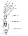
また、例えば日本においては、一般に、車両の運転席は車室内右側に配設されて、車両は左車線を走行する。一方、欧米等においては、一般に、車両の運転席は車室内左側に配設されて、車両は右車線を走行する。いずれの場合であれ、一般に、車両の運転席が車室内中央に配設されることは少なく、偏倚した位置に配設されている。 In Japan, for example, the driver's seat of the vehicle is generally arranged on the right side of the passenger compartment, and the vehicle travels in the left lane. On the other hand, in Europe and the United States, the driver's seat of the vehicle is generally disposed on the left side of the passenger compartment, and the vehicle travels in the right lane. In any case, in general, the driver's seat of the vehicle is rarely arranged in the center of the passenger compartment, and is arranged at a biased position.
さらに、例えば日本においては、一般に、左側前照灯は右側前照灯よりも上方に向けて配設されており、自車両の前方左側の方が前方右側よりも照射距離が長くなるように配光されている。一方、例えば欧州においては、一般に、右側前照灯は左側前照灯よりも上方に向けて配設されており、自車両の前方右側の方が前方左側よりも照射距離が長くなるように配光されている。 Further, for example, in Japan, the left headlamp is generally arranged upward from the right headlamp so that the irradiation distance on the front left side of the vehicle is longer than the front right side. It is shining. On the other hand, in Europe, for example, the right headlight is generally arranged upward from the left headlight, and the front right side of the vehicle is arranged so that the irradiation distance is longer than the front left side. It is shining.
このように、運転席が偏倚した位置に配設されるため、さらには、配光が異なるため、道路が所定の勾配で傾斜している場合、カーブの線型が左カーブであるか、あるいは、右カーブであるかによって、運転者が望ましいとする前照灯の照射方向が異なることが、発明者らによって確認されている。 In this way, because the driver's seat is arranged at a biased position and the light distribution is different, if the road is inclined at a predetermined slope, the curve linearity is a left curve, or It has been confirmed by the inventors that the direction of the headlamp illumination desired by the driver differs depending on whether it is a right curve.
詳しくは、カーブ線型が運転席側に曲がる線型であって、かつ、自車両の現在地の前方方向における勾配が増大(日本では上りの右カーブ)するとき、前照灯による自車両前方の照射距離は、平坦路におけるよりも、短くなってしまう。そうした場合にあっては、スイブル角度が大きくなるように設定する方が、前照灯による自車両前方の照射距離が長くなる可能性が高まる。すなわち、運転者がカーブ線型を視認可能となる可能性が高まる。 Specifically, when the curve linear type is a linear type that bends toward the driver's seat and the gradient in the forward direction of the current location of the host vehicle increases (upward right curve in Japan), the irradiation distance in front of the host vehicle by the headlamp Becomes shorter than on a flat road. In such a case, setting the swivel angle to be larger increases the possibility that the irradiation distance in front of the vehicle by the headlamp becomes longer. That is, the possibility that the driver can visually recognize the curve linear shape increases.
一方、カーブ線型が運転席側に曲がる線型であって、かつ、自車両の現在地の前方方向における勾配が減少(日本では下りの右カーブ)するとき、自車両の前照灯はそもそも水平方向に照射されるため、前照灯のスイブル角度を制御しようとしまいと、運転者によるカーブ線型の視認の容易さは影響されない。 On the other hand, when the curved line type is a linear type that bends toward the driver's seat, and the slope in the forward direction of the current location of the host vehicle decreases (downward right curve in Japan), the headlight of the own vehicle is originally horizontal. Since it is irradiated, the ease of visual recognition of the curve line type by the driver is not affected when trying to control the swivel angle of the headlamp.
他方、カーブ線型が助手席側に曲がる線型であるとき(日本では左カーブ)、運転者が最も注視する箇所は、カーブ線型のうち、手前の曲線(自車両が走行する車線の路側)ではなく、奥(前方)の曲線(対向車線の路側)である。そして、既述したように、助手席側の前照灯は運転席側の前照灯よりも上方に向けて配設されており、自車両の前方助手席側の方が前方運転席側よりも照射距離が長くなるように配光されているため、そもそも、そうした注視箇所は十分に照射されている。したがって、カーブ線型が助手席側に曲がる線型であるとき、スイブル角度を制御する要求は小さく、また、スイブル角度を制御しても、運転者がカーブ線型をさらに容易に視認できるようになることに寄与しない。 On the other hand, when the curve line type is a line type that turns to the passenger seat side (left curve in Japan), the driver's most watched point is not the curve line type in front (the road side of the lane on which the vehicle is traveling) The back (front) curve (on the opposite lane). As described above, the front-side lamp on the passenger seat side is disposed upward from the front-side lamp on the driver's seat side, and the front passenger seat side of the vehicle is closer to the front driver's seat side. Since the light is distributed so that the irradiation distance becomes longer, the gaze point is sufficiently irradiated in the first place. Therefore, when the curve line type is a line type that bends toward the passenger seat, the demand for controlling the swivel angle is small, and even if the swivel angle is controlled, the driver can more easily see the curve line type. Does not contribute.
その点、上記請求項6に記載の構成において、例えば請求項7に記載の発明のように、前記照射角度算出部は、当該自車両が運転席側に曲がるとき、スイブル角度θを下式(10)に基づき算出するとともに、助手席側に曲がるとき、スイブル角度θを下式(11)に基づき算出し、前記照射角度制御部は、前記照射角度算出部にて算出されたスイブル角度に前記前照灯を制御することが望ましい。あるいは、上記請求項12に記載の構成において、例えば請求項13に記載の発明のように、前記照射角度算出部は、当該自車両が運転席側に曲がるとき、スイブル角度θを下式(10)に基づき算出するとともに、助手席側に曲がるとき、スイブル角度θを下式(11)に基づき算出し、前記照射角度制御部は、前記照射角度算出部にて算出されたスイブル角度に前記前照灯を制御することが望ましい。これにより、上述した実情に沿うように、前照灯のスイブル角度を的確に制御することができるようになる。
(数10)
スイブル角度θ=定数α3+β3×カーブ半径R+γ3×距離L+ε3×勾配情報φ・・
・(10)
(数11)
スイブル角度θ=定数α4+β4×カーブ半径R+γ4×距離L・・・(11)
他方、上記目的を達成するため、請求項2に記載の発明では、車両に配設される前照灯の照射角度を制御する前照灯照射角度制御システムであって、自車両の現在地を検出する自車両検出手段と、道路情報を記憶保持する記憶保持手段と、前記自車両の現在地及び前記道路情報に基づいて、自車両が進入するカーブの半径を取得する半径情報取得手段と、前記自車両の現在地及び前記道路情報に基づいて、自車両の現在地から前記カーブの開始点までの距離情報を取得する距離情報取得手段と、前記カーブが、異なる方向へ連続して曲がる線型を有するS字カーブであるか否かを前記道路情報に基づいて判定するとともに、その判定結果である線型情報を取得する線型情報取得手段と、自車両が走行する道路の現在地の前方方向における当該自車両の前後方向の勾配情報を取得する勾配情報取得手段と、前記カーブ半径、前記距離情報、前記線型情報、及び前記勾配情報に基づいて、前記前照灯の照射角度を算出する照射角度算出部と、前記照射角度算出部にて算出された前記照射角度に前記前照灯を制御する照射角度制御部とを備え、前記線型情報取得手段は、前記カーブがS字カーブであると判定するとき、前記線型情報Cとして「1」を出力するとともに、前記カーブがS字カーブでないと判定するとき、前記線型情報Cとして「0」を出力し、前記距離情報取得手段は、前記カーブの開始点を基準として、自車両の現在地から前記カーブの開始点までの距離情報L[m]を取得し、前記照射角度算出部は、カーブ半径R[m]、距離情報L[m]、線型情報C、及び勾配情報φ[%]を独立変数として、これら独立変数がそれぞれ所定係数β5〜ε5にて重み付けされるとともに、定数α5を含めた下式(12)に基づいて、自車両前方を基準とするスイブル角度θ[度]を前記前照灯の照射角度として算出し、前記照射角度制御部は、前記照射角度算出部にて算出された前記スイブル角度θに前記前照灯を制御する前照灯照射角度制御システムにおいて、前記カーブがS字カーブであると判定されるとき、前記カーブがS字カーブでないと判定されるときに比べて、前記前照灯の照射方向を当該自車両の前方正面に近づけるべく、前記スイブル角度θの絶対値の大きさが小さくなるように、前記係数及び定数が定められていることを特徴とする。
また、請求項8に記載の発明では、車両に配設される前照灯の照射角度を制御する前照灯照射角度制御システムであって、自車両の現在地を検出する自車両検出手段と、道路情報を記憶保持する記憶保持手段と、前記自車両の現在地及び前記道路情報に基づいて、自車両が進入するカーブの半径を取得する半径情報取得手段と、前記自車両の現在地及び前記道路情報に基づいて、自車両の現在地から前記カーブの開始点までの距離情報を取得する距離情報取得手段と、前記カーブが、異なる方向へ連続して曲がる線型を有するS字カーブであるか否かを前記道路情報に基づいて判定するとともに、その判定結果である線型情報を取得する線型情報取得手段と、自車両が走行する道路の現在地の前方方向における当該自車両の前後方向の勾配情報を取得する勾配情報取得手段と、前記カーブ半径、前記距離情報、前記線型情報、及び前記勾配情報に基づいて、前記前照灯の照射角度を算出する照射角度算出部と、前記照射角度算出部にて算出された前記照射角度に前記前照灯を制御する照射角度制御部とを備え、前記線型情報取得手段は、前記カーブがS字カーブであると判定するとき、前記線型情報Cとして「1」を出力するとともに、前記カーブがS字カーブでないと判定するとき、前記線型情報Cとして「0」を出力し、前記距離情報取得手段は、前記カーブの開始点を基準として、自車両の現在地から前記カーブの開始点までの距離情報L[m]を取得し、前記照射角度算出部は、カーブ半径R[m]、距離情報L[m]、線型情報C、及び勾配情報φ[%]を独立変数として、これら独立変数がそれぞれ所定係数β5〜ε5にて重み付けされるとともに、定数α5を含めた下式(12)に基づいて、自車両前方を基準とするスイブル角度θ[度]を前記前照灯の照射角度として算出し、前記照射角度制御部は、前記照射角度算出部にて算出された前記スイブル角度θに前記前照灯を制御する前照灯照射角度制御システムにおいて、前記カーブの半径が大きくなるほど、前記前照灯の照射方向を当該自車両の前方正面に近づけるべく、前記スイブル角度の絶対値の大きさが小さくなるように、前記係数及び定数が定められていることを特徴とする。
また、請求項14に記載の発明では、車両に配設される前照灯の照射角度を制御する前照灯照射角度制御システムであって、自車両の現在地を検出する自車両検出手段と、道路情報を記憶保持する記憶保持手段と、前記自車両の現在地及び前記道路情報に基づいて、自車両が進入するカーブの半径を取得する半径情報取得手段と、前記自車両の現在地及び前記道路情報に基づいて、自車両の現在地から前記カーブの開始点までの距離情報を取得する距離情報取得手段と、前記カーブが、異なる方向へ連続して曲がる線型を有するS字カーブであるか否かを前記道路情報に基づいて判定するとともに、その判定結果である線型情報を取得する線型情報取得手段と、自車両が走行する道路の現在地の前方方向における当該自車両の前後方向の勾配情報を取得する勾配情報取得手段と、前記カーブ半径、前記距離情報、前記線型情報、及び前記勾配情報に基づいて、前記前照灯の照射角度を算出する照射角度算出部と、前記照射角度算出部にて算出された前記照射角度に前記前照灯を制御する照射角度制御部とを備え、前記線型情報取得手段は、前記カーブがS字カーブであると判定するとき、前記線型情報Cとして「1」を出力するとともに、前記カーブがS字カーブでないと判定するとき、前記線型情報Cとして「0」を出力し、前記距離情報取得手段は、前記カーブの開始点を基準として、自車両の現在地から前記カーブの開始点までの距離情報L[m]を取得し、前記照射角度算出部は、カーブ半径R[m]、距離情報L[m]、線型情報C、及び勾配情報φ[%]を独立変数として、これら独立変数がそれぞれ所定係数β5〜ε5にて重み付けされるとともに、定数α5を含めた下式(12)に基づいて、自車両前方を基準とするスイブル角度θ[度]を前記前照灯の照射角度として算出し、前記照射角度制御部は、前記照射角度算出部にて算出された前記スイブル角度θに前記前照灯を制御する前照灯照射角度制御システムにおいて、前記距離が短くなるほど、前記前照灯の照射方向を当該自車両が曲がる方向に向けるべく、前記スイブル角度の絶対値が大きくなるように、前記係数及び定数が定められていることを特徴とする。
(数12)
スイブル角度θ=定数α5+β5×カーブ半径R+γ5×距離L+δ5×線型情報C+ε5×勾配情報φ・・・(12)
In that respect, in the configuration according to
(Equation 10)
Swivel angle θ = constant α3 + β3 × curve radius R + γ3 × distance L + ε3 × gradient information φ
・ (10)
(Equation 11)
Swivel angle θ = constant α4 + β4 × curve radius R + γ4 × distance L (11)
On the other hand, in order to achieve the above object, according to the second aspect of the present invention, there is provided a headlamp illumination angle control system for controlling the illumination angle of a headlamp disposed in a vehicle, wherein the present location of the host vehicle is detected. A host vehicle detection unit that stores and holds road information; a radius information acquisition unit that acquires a radius of a curve on which the host vehicle enters based on the current location of the host vehicle and the road information; Based on the current location of the vehicle and the road information, distance information acquisition means for acquiring distance information from the current location of the host vehicle to the start point of the curve, and an S-shape having a linear shape in which the curve bends continuously in different directions Whether or not the vehicle is a curve is determined based on the road information, and linear information acquisition means for acquiring linear information as a result of the determination, and the forward direction of the current location of the road on which the vehicle is traveling Gradient information acquisition means for acquiring gradient information in the longitudinal direction of the vehicle, and an irradiation angle calculation unit that calculates an irradiation angle of the headlamp based on the curve radius, the distance information, the linear information, and the gradient information And an irradiation angle control unit that controls the headlamp at the irradiation angle calculated by the irradiation angle calculation unit , and the linear information acquisition unit determines that the curve is an S-shaped curve. When “1” is output as the linear information C and when it is determined that the curve is not an S-shaped curve, “0” is output as the linear information C, and the distance information acquisition means is a start point of the curve Is used to obtain distance information L [m] from the current location of the vehicle to the start point of the curve, and the irradiation angle calculation unit calculates the curve radius R [m], the distance information L [m], and the linear information C. And gradient information With φ [%] as an independent variable, these independent variables are weighted by predetermined coefficients β5 to ε5, respectively, and based on the following expression (12) including the constant α5, the swivel angle θ with reference to the front of the host vehicle [Degree] is calculated as the irradiation angle of the headlamp, and the irradiation angle control section controls the headlamp irradiation angle control to control the headlamp to the swivel angle θ calculated by the irradiation angle calculation section. In the system, when it is determined that the curve is an S-shaped curve, the irradiation direction of the headlamp should be closer to the front front of the host vehicle than when the curve is determined not to be an S-shaped curve. The coefficient and the constant are determined such that the absolute value of the swivel angle θ is small.
The invention according to
The invention according to
(Equation 12)
Swivel angle θ = constant α5 + β5 × curve radius R + γ5 × distance L + δ5 × linear information C + ε5 × gradient information φ (12)
前照灯照射角度制御システムとしてのこのような構成では、まず、自車両検出手段にて検出された自車両の現在地、及び、記憶保持手段に記憶保持された道路情報に基づいて、半径情報取得手段を通じて、自車両が進入するカーブの半径についての情報が取得される。また、同様に、自車両の現在地及び道路情報に基づいて、距離情報取得手段を通じて、自車両の現在地からカーブの開始点までの距離についての情報が取得される。また同様に、自車両の現在地及び道路情報に基づいて、線型情報取得手段を通じて、自車両が進入するカーブがS字カーブであるか否かについて判定され、その判定結果が線型情報として取得される。そしてさらに、勾配情報取得手段を通じて、自車両が走行する道路の現在地における当該自車両の前後方向の勾配情報が取得される。こうして各種手段によって取得されたカーブ半径、距離情報、線型情報、及び勾配情報に基づいて、前照灯照射角度算出部にて前照灯の照射角度が算出される。そして、算出された照射角度に、前照灯角度制御手段を通じて、前照灯が制御されるようになる。 In such a configuration as a headlamp illumination angle control system, first, radius information is acquired based on the current location of the host vehicle detected by the host vehicle detection means and road information stored and held in the memory holding means. Through the means, information about the radius of the curve on which the host vehicle enters is acquired. Similarly, information on the distance from the current location of the host vehicle to the start point of the curve is acquired through the distance information acquisition unit based on the current location and road information of the host vehicle. Similarly, based on the current location and road information of the host vehicle, it is determined whether or not the curve on which the host vehicle enters is an S-shaped curve through the linear information acquisition means, and the determination result is acquired as linear information. . Further, through the gradient information acquisition means, gradient information in the front-rear direction of the vehicle at the current location of the road on which the vehicle is traveling is acquired. Based on the curve radius, distance information, linear information, and gradient information acquired by various means in this way, the headlamp irradiation angle calculation unit calculates the headlamp irradiation angle. Then, the headlamp is controlled to the calculated irradiation angle through the headlamp angle control means.
上記構成では、課題の欄に記載した従来技術のように実際の車輪速や操舵角に基づいて前照灯の照射角度が算出されるのでなく、上記各種手段を通じて予め取得された情報に基づいて前照灯の照射角度が算出される。したがって、前照灯の照射角度の制御は、自車両が実際にカーブに入る直前に実行されるのではなく、自車両が実際にカーブに入る前に、運転者がカーブの深さやカーブのきつさ等を視認する時期に合わせて、予め実行することができるようになる。 In the above configuration, the headlamp illumination angle is not calculated based on the actual wheel speed and steering angle as in the conventional technique described in the column of the problem, but based on information acquired in advance through the various means. The irradiation angle of the headlamp is calculated. Therefore, the control of the headlight illumination angle is not performed immediately before the vehicle actually enters the curve, but before the vehicle actually enters the curve, the driver can check the depth of the curve and the tightness of the curve. This can be executed in advance in accordance with the time when the user etc. is visually recognized.
また、自車両が進入するカーブが、例えばS字カーブのように、異なる方向へ連続して曲がる線型であるような場合には、手前のカーブ線型に合わせて前照灯の照射角度を制御した後、続くカーブ線型に合わせて急激に前照灯の照射角度を制御することとなる。そして、課題の欄に記載した従来の前照灯照射角度制御装置では、前照灯の照射角度の制御が実際に開始される時期が、自車両が実際にカーブに入る直前であるため、運転者が手前のカーブ線型を視認することができたとしても、前照灯による照射が遅れ、運転者が後に続くカーブ線型を視認することができなくなるおそれもある。さらに、自車両が進入するカーブが例えば上り勾配であるときには、前照灯による自車両前方の照射距離は、平坦路におけるよりも短くなることが、発明者らによって確認されている。 In addition, when the curve in which the host vehicle enters is a linear shape that bends continuously in different directions, such as an S-curve, for example, the irradiation angle of the headlamp is controlled in accordance with the curve shape in front. Thereafter, the irradiation angle of the headlamp is suddenly controlled in accordance with the following curve linear pattern. And in the conventional headlamp illumination angle control device described in the column of the problem, since the time when the control of the illumination angle of the headlamp is actually started is just before the vehicle actually enters the curve, Even if the driver can visually recognize the curve line shape in front, the irradiation with the headlamp may be delayed, and the driver may not be able to visually recognize the curve line shape that follows. Furthermore, the inventors have confirmed that when the curve into which the host vehicle enters is, for example, an upward slope, the irradiation distance ahead of the host vehicle by the headlamp is shorter than that on a flat road.
その点、上記構成では、線型情報取得手段を通じて取得される線型情報は、カーブがS字カーブであるか否かの判定結果であるため、手前のカーブ線型だけでなく、続くカーブ線型も見据えて、前照灯の照射角度を算出することができるようになる。さらに、上記構成では、照射角度算出部は、勾配情報に基づいて前照灯の照射角度を算出しているため、道路の勾配を考慮した上で、前照灯の照射角度を制御することができるようになる。したがって、運転者が当該自車両の進入するカーブの線型をより的確に予め視認することができるようになる。
また、前照灯照射角度制御システムとしての上記請求項2,8,14に記載の構成によれば、カーブ半径R、距離L、線型情報C、及び勾配情報φを考慮して立式された上式(12)にて示される一次式を通じて、簡単な演算にて、スイブル角度θを算出することができるようになる。
In that respect, in the above configuration, since the linear information acquired through the linear information acquisition means is a determination result of whether or not the curve is an S-shaped curve, not only the previous curve linear type but also the following curved linear types are also expected. The irradiation angle of the headlamp can be calculated. Furthermore, in the above configuration, since the irradiation angle calculation unit calculates the irradiation angle of the headlamp based on the gradient information, the irradiation angle of the headlamp can be controlled in consideration of the road gradient. become able to. Therefore, the driver can visually recognize in advance the linear shape of the curve into which the host vehicle enters.
Moreover, according to the structure of the said
また、例えば日本においては、一般に、車両の運転席は車室内右側に配設されて、車両は左車線を走行する。一方、欧米等においては、一般に、車両の運転席は車室内左側に配設されて、車両は右車線を走行する。いずれの場合であれ、一般に、車両の運転席が車室内中央に配設されることは少なく、偏倚した位置に配設されている。 In Japan, for example, the driver's seat of the vehicle is generally arranged on the right side of the passenger compartment, and the vehicle travels in the left lane. On the other hand, in Europe and the United States, the driver's seat of the vehicle is generally disposed on the left side of the passenger compartment, and the vehicle travels in the right lane. In any case, in general, the driver's seat of the vehicle is rarely arranged in the center of the passenger compartment, and is arranged at a biased position.
さらに、例えば日本においては、一般に、左側前照灯は右側前照灯よりも上方に向けて配設されており、自車両の前方左側の方が前方右側よりも照射距離が長くなるように配光されている。一方、例えば欧州においては、一般に、右側前照灯は左側前照灯よりも上方に向けて配設されており、自車両の前方右側の方が前方左側よりも照射距離が長くなるように配光されている。 Further, for example, in Japan, the left headlamp is generally arranged upward from the right headlamp so that the irradiation distance on the front left side of the vehicle is longer than the front right side. It is shining. On the other hand, in Europe, for example, the right headlight is generally arranged upward from the left headlight, and the front right side of the vehicle is arranged so that the irradiation distance is longer than the front left side. It is shining.
このように、運転席が偏倚した位置に配設されるため、さらには、配光が異なるため、道路が所定の勾配で傾斜している場合、カーブの線型が左カーブであるか、あるいは、右カーブであるかによって、運転者が望ましいとする前照灯の照射方向が異なることが、発明者らによって確認されている。 In this way, because the driver's seat is arranged at a biased position and the light distribution is different, if the road is inclined at a predetermined slope, the curve linearity is a left curve, or It has been confirmed by the inventors that the direction of the headlamp illumination desired by the driver differs depending on whether it is a right curve.
詳しくは、カーブ線型が運転席側に曲がる線型であって、かつ、自車両の現在地の前方方向における勾配が増大(日本では上りの右カーブ)するとき、前照灯による自車両前方の照射距離は、平坦路におけるよりも、短くなってしまう。そうした場合にあっては、スイブル角度が大きくなるように設定する方が、前照灯による自車両前方の照射距離が長くなる可能性が高まる。すなわち、運転者がカーブ線型を視認可能となる可能性が高まる。 Specifically, when the curve linear type is a linear type that bends toward the driver's seat and the gradient in the forward direction of the current location of the host vehicle increases (upward right curve in Japan), the irradiation distance in front of the host vehicle by the headlamp Becomes shorter than on a flat road. In such a case, setting the swivel angle to be larger increases the possibility that the irradiation distance in front of the vehicle by the headlamp becomes longer. That is, the possibility that the driver can visually recognize the curve linear shape increases.
一方、カーブ線型が運転席側に曲がる線型であって、かつ、自車両の現在地の前方方向における勾配が減少(日本では下りの右カーブ)するとき、自車両の前照灯はそもそも水平方向に照射されるため、前照灯のスイブル角度を制御しようとしまいと、運転者によるカーブ線型の視認の容易さに影響を与えない。 On the other hand, when the curved line type is a linear type that bends toward the driver's seat, and the slope in the forward direction of the current location of the host vehicle decreases (downward right curve in Japan), the headlight of the own vehicle is originally horizontal. Because it is irradiated, it does not affect the ease of visual recognition of the curve line type by the driver if the swivel angle of the headlamp is to be controlled.
他方、カーブ線型が助手席側に曲がる線型であるとき(日本では左カーブ)、運転者が最も注視する箇所は、カーブ線型のうち、手前の曲線(自車両が走行する車線の路側)ではなく、奥(前方)の曲線(対向車線の路側)である。そして、既述したように、助手席側の前照灯は運転席側の前照灯よりも上方に向けて配設されており、自車両の前方助手席側の方が前方運転席側よりも照射距離が長くなるように配光されているため、そもそも、そうした注視箇所は十分に照射されている。したがって、カーブ線型が助手席側に曲がる線型であるとき、スイブル角度を制御する要求は小さく、また、スイブル角度を制御しても、運転者がカーブ線型をさらに容易に視認できるようになることに寄与しない。 On the other hand, when the curve line type is a line type that turns to the passenger seat side (left curve in Japan), the driver's most watched point is not the curve line type in front (the road side of the lane on which the vehicle is traveling) The back (front) curve (on the opposite lane). As described above, the front-side lamp on the passenger seat side is disposed upward from the front-side lamp on the driver's seat side, and the front passenger seat side of the vehicle is closer to the front driver's seat side. Since the light is distributed so that the irradiation distance becomes longer, the gaze point is sufficiently irradiated in the first place. Therefore, when the curve line type is a line type that bends toward the passenger seat, the demand for controlling the swivel angle is small, and even if the swivel angle is controlled, the driver can more easily see the curve line type. Does not contribute.
その点、上記請求項2に記載の構成において、例えば請求項3に記載の発明のように、前記照射角度算出部は、当該自車両が運転席側に曲がるとき、スイブル角度θを下式(13)に基づき算出するとともに、助手席側に曲がるとき、スイブル角度θを下式(14)に基づき算出し、前記照射角度制御部は、前記照射角度算出部にて算出されたスイブル角度に前記前照灯を制御することが望ましい。あるいは、上記請求項8に記載の構成において、例えば請求項9に記載の発明のように、前記照射角度算出部は、当該自車両が運転席側に曲がるとき、スイブル角度θを下式(13)に基づき算出するとともに、助手席側に曲がるとき、スイブル角度θを下式(14)に基づき算出し、前記照射角度制御部は、前記照射角度算出部にて算出されたスイブル角度に前記前照灯を制御することが望ましい。あるいは、上記請求項14に記載の構成において、例えば請求項15に記載の発明のように、前記照射角度算出部は、当該自車両が運転席側に曲がるとき、スイブル角度θを下式(13)に基づき算出するとともに、助手席側に曲がるとき、スイブル角度θを下式(14)に基づき算出し、前記照射角度制御部は、前記照射角度算出部にて算出されたスイブル角度に前記前照灯を制御することが望ましい。これにより、上述した実情に沿うように、前照灯のスイブル角度をさらに的確に制御することができるようになる。
(数13)
スイブル角度θ=定数α6+β6×カーブ半径R+γ6×距離L+δ6×線型情報C+ε
6×勾配情報φ・・・(13)
(数14)
スイブル角度θ=定数α7+β7×カーブ半径R+γ7×距離L+δ7×線型情報C・・
・(14)
In this respect, in the structure described in
(Equation 13)
Swivel angle θ = constant α6 + β6 × curve radius R + γ6 × distance L + δ6 × linear information C + ε
6 x Gradient information φ (13)
(Equation 14)
Swivel angle θ = constant α7 + β7 × curve radius R + γ7 × distance L + δ7 × linear information C.
・ (14)
なお、上記請求項1〜15のいずれか一項に記載の構成において、例えば請求項16に記載の発明のように、前記定数及び前記係数は、カーブ開始点及び該カーブ開始点の所定距離手前の複数の地点に実車を静止させるとともに、この静止された実車の運転席に着座した複数の被験者が、カーブの線型を最も視認しやすいと感じるスイブル角度を、予め定められた複数のスイブル角度の中から選択する実験を通じて決定された値とすることが望ましい。これにより、被験者の望むスイブル角度を実際に実現することができるようになる。
In the configuration according to any one of
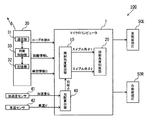
以下、本発明にかかる前照灯照射角度制御システムの一実施の形態について、図1〜図3を参照しつつ説明する。なお、図1は、本実施の形態の前照灯照射角度制御システム100全体のブロック図である。
Hereinafter, an embodiment of a headlamp irradiation angle control system according to the present invention will be described with reference to FIGS. FIG. 1 is a block diagram of the entire headlamp illumination
図1に示されるように、前照灯照射角度制御システム100は、基本的に、各種演算を実行するマイクロコンピュータ1、自車両が走行する道路についての各種情報を取得するカーナビゲーション装置30、図示しない自車両に作用する加速度を検出する加速度センサ41、自車両の車速を車輪速に基づき検出する車速センサ42、自車両前方の左側を照射する左側前照灯50L及び自車両前方の右側を照射する右側前照灯50R等々を備えている。
As shown in FIG. 1, the headlamp illumination
ここで、カーナビゲーション装置30は、例えばGPS衛星との通信を行う通信部31、該通信部31を介して取得された自車両の現在地に関する情報や自車両周辺の道路情報等々を記憶保持する記憶部32(記憶保持手段)、これら通信部31や記憶部32を制御する判断制御部33等々を備える。ちなみに、記憶部32は、GPS衛星から得られた道路情報を記憶保持するだけでなく、自車両が走行することで新たに得られた情報をさらに追加して記憶保持したり、現在記憶保持している道路情報を更新したりすることもできる。判断制御部33は、通信部31から取得した自車両の現在地や、記憶部32に記憶した道路情報に基づいて、自車両が進入するカーブ半径R[m]についての情報や自車両の現在地からカーブの開始点までの距離L[m]についての情報を取得するとともに、カーブがS字カーブであるか否かについての判断を実行し、その判断結果である線型情報Cを取得する。そして、カーナビゲーション装置30(判断制御部33)は、図1に示されるように、カーブ半径R、距離情報L及び線型情報Cを、自車両内に搭載されるマイクロコンピュータ1に出力する。なお、判断制御部33は、カーブの線型がS字であると判断すると、線型情報Cとして「1」を出力するとともに、カーブの線型がS字でないと判断すると、線型情報Cとして「0」を出力する。
Here, the
記憶部32に記憶保持される道路情報について詳しく説明する。道路情報は、図示しない表示装置に表示する表示範囲をメッシュ状に分割し、パーセル(地図区画)と呼ばれる個々の分割範囲ごとに、主に、自然地形や線路など道路地図を表示する際の背景となる背景データと、実際の道路に即して道路を表示するための道路データとを有する。このうち、道路データは、1つのパーセルに含まれる全ての道路について、道路が分岐、交差、連結などする地点をノードとして規定し、そのノード間を結ぶリンクによって構成される。ただし、道路の形状が直線以外の場合、実際の道路の形状を模擬するため、ノード間に形状補間点が設定される。この場合、ノードと形状補間点との間や形状補間点同士を結ぶ線分はセグメントと呼ばれ、リンクは複数のセグメントから構成される。 The road information stored and held in the storage unit 32 will be described in detail. For road information, the display range displayed on a display device (not shown) is divided into meshes, and the background when displaying road maps such as natural landforms and tracks mainly for each divided range called a parcel (map section) Background data, and road data for displaying the road according to the actual road. Of these, the road data is configured by defining links where the roads branch, intersect, and connect as nodes for all roads included in one parcel and link the nodes. However, when the road shape is other than a straight line, a shape interpolation point is set between the nodes in order to simulate the actual road shape. In this case, a line segment connecting the node and the shape interpolation point or connecting the shape interpolation points is called a segment, and the link is composed of a plurality of segments.
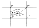
また、図6を用いて、判断制御部33にて実行されるカーブがS字カーブであるか否かについての判定方法を説明する。そもそも、S字カーブは、異なる方向へ曲がる2つのカーブが連結されたカーブである。そこで、判断制御部33は、自車両の現在位置から所定距離前方までの道路情報を取得する。そして、取得された道路情報に含まれる、連続するセグメントの方位が同一方向に変化する状態から、その同一方向とは異なる方向へと、セグメントの方位の変化方向が反転したときに、S字カーブであると判定する。
Moreover, the determination method about whether the curve performed in the
例えば、図6に示す例では、自車両が地点P1に位置する場合、その地点から前方に伸びる道路は右方向にカーブしているので、その道路に対応するセグメントSg11、Sg12、Sg13の方位は、時計回りの同一方向に変化していく。 For example, in the example shown in FIG. 6, when the host vehicle is located at the point P1, the road extending forward from the point is curved in the right direction, so the directions of the segments Sg11, Sg12, Sg13 corresponding to the road are , Change in the same clockwise direction.
しかし、道路は、変曲点P0を境として右カーブから左カーブに変化しているので、変曲点P0後のセグメントSg21、Sg22、Sg23の方位は、各々の前段のセグメントの方位に対して反時計回りの方向に変化する。このように、道路がS字カーブであるとき、その道路を細分化したセグメントの方位は、一定方向に変化した後に、変曲点において変化方向が反転し、今度は逆方向への方位変化を示す。したがって、上述したように、各セグメントの方位の変化方向が反転したことに基づいて、S字カーブであるか否かを判定することができる。 However, since the road changes from the right curve to the left curve at the inflection point P0, the direction of the segments Sg21, Sg22, Sg23 after the inflection point P0 is relative to the direction of each preceding segment. It changes in the counterclockwise direction. Thus, when the road is an S-curve, the direction of the segment that subdivides the road changes to a certain direction, and then the direction of change reverses at the inflection point, and this time the direction changes to the opposite direction. Show. Therefore, as described above, based on the fact that the direction of change in the direction of each segment is reversed, it is possible to determine whether the segment is an S-shaped curve.
なお、一旦、自車両の走行する道路がS字カーブであると判定された場合には、車両の走行に伴って、新たに上記所定距離範囲に含まれることになったセグメントが、前段のセグメントに対して、上記逆方向への方位変化を示すことを条件として、その判定結果を、自車両が変曲点に達するまで維持することが望ましい。また、上述した所定距離は、自車両の走行速度に応じて変化し、速度が高くなるほど長くなるように設定される。 If it is determined that the road on which the host vehicle is traveling is an S-curve, the segment that is newly included in the predetermined distance range as the vehicle travels is the previous segment. On the other hand, it is desirable to maintain the determination result until the host vehicle reaches the inflection point on the condition that the direction change in the reverse direction is indicated. Moreover, the predetermined distance mentioned above changes according to the traveling speed of the own vehicle, and is set so that it becomes so long that the speed becomes high.
また、上記左側前照灯50L及び右側前照灯50Rは、基本的には、従来使用されている技術を利用している。すなわち、日本においては、左側前照灯50Lが自車両の助手席側に配設された前照灯に相当し、右側前照灯50Rが自車両の運転席側に配設された前照灯に相当する。なお、上記各種センサ41及び42については、従来使用されている技術を利用しているため、ここでの詳しい説明を割愛する。
The
マイクロコンピュータ1は、実際には、各種制御処理や演算処理を行うCPU、各種プログラムやデータを保存するための読み取り専用メモリ(ROM)や書き込み可能なメモリ(RAM)等のメモリを含む記憶装置、A/D変換器等の入力回路、出力回路、及び電源回路等によって構成される。しかし、ここでは、機能的に、後述する勾配算出部40、照射角度算出部10及び照射角度制御部20を含むものとして、概念的に説明する。
The
図1に示されるように、マイクロコンピュータ1は、勾配算出部40を備える。この勾配算出部40は、加速度センサ41及び車速センサ42のセンサ出力値を取り込むとともに、自車両が走行する道路の現在地における当該自車両の前後方向の勾配についての情報(勾配φ)を算出する。詳しくは、上り坂を登坂中の自車両60を図2に示す。この図2に示されるように、自車両60に対しては、自車両60の走行方向の加速度G1と、自車両60の鉛直方向下方に働く重力加速度gが作用する。このうち、加速度G1は、車速センサ42のセンサ出力値である車速Vを時間で微分処理することにより求めることができる。また、自車両60の走行方向を検出軸として配設された加速度センサ41により検出される自車両60の走行方向成分の加速度を加速度G、重力加速度がgの自車両60の走行方向成分をG2とすると、それぞれの成分は、ベクトル和よりG=G1+G2として表される。ここで、両センサの加速度情報から得られる道路の勾配を勾配φとすると、G2=g×sinφとの関係から、下式(15)のように示すことができる。
(数15)
φ=sin-1[(G−G1)/g]・・・(15)
なお、勾配算出部40は、上式(15)に基づく勾配φの算出は所定の周期ごとに実行しており、算出した勾配φを照射角度算出部10に出力する。このようにして、勾配算出部40、加速度センサ41及び車速センサ42によって、勾配情報取得手段が構成されている。
As shown in FIG. 1, the
(Equation 15)
φ = sin−1 [(G−G1) / g] (15)
The
また、図1に示されるように、マイクロコンピュータ1は、照射角度算出部10を備える。照射角度算出部10は、既述したカーナビゲーション装置30からカーブ半径R、距離L、及び線型情報Cを取り込むとともに、勾配算出部40から勾配φを取り込む。そして、取り込んだこれら各種情報に基づいて、左側前照灯50L及び右側前照灯50Rのスイブル角度θ1及びθ2をそれぞれ算出する。なお、スイブル角度θ1及びθ2の算出に際して使用するモデルについては、後述する。そして、照射角度算出部10は、算出したスイブル角度θ1及びθ2を照射角度制御部20に出力する。
Moreover, as shown in FIG. 1, the
また、図1に示されるように、マイクロコンピュータ1は、照射角度制御部20を備える。照射角度制御部20は、上記照射角度算出部10から出力されるスイブル角度θ1及びθ2を取り込む。そして、照射角度制御部20は、自車両が左側(日本では助手席側)へ曲がるとき、すなわち、進入するカーブが左カーブであるとき、左側前照灯50Lがモデルに基づき算出されたスイブル角度θ1となるように制御する。このとき、照射角度制御部20は、右側前照灯50Rがスイブル角度θ2=0となるように、すなわち、自車両の前方正面を照射するように、右側前照灯50Rを制御する。一方、照射角度制御部20は、自車両が右側(日本では運転席側)へ曲がるとき、すなわち、進入するカーブが右カーブであるとき、右側前照灯50Rがモデルに基づき算出されたスイブル角度θ2となるように制御する。このとき、照射角度制御部20は、左側前照灯50Lがスイブル角度θ1=0となるように、すなわち、自車両の前方正面を照射するように、左側前照灯50Lを制御する。
As shown in FIG. 1, the
以下、上記照射角度算出部10において、スイブル角度θ1及びθ2の算出に際して使用されるモデルについて説明する。
Hereinafter, a model used in calculating the swivel angles θ1 and θ2 in the irradiation
通常、車両を運転する運転者は、自車両のハンドルを操舵する前に、すなわち、自車両が実際にカーブに入る手前で、そのカーブの深さやカーブのきつさ等を予め視認する。しかしながら、例えば夜間に車両を運転中、特にカーブに進入する際、所定時間経過後に自車両60が到達すると予測される到達地点が照射範囲に収まるように前照灯の照射方向が制御されていないと、そうしたカーブの線型を視認することができない。さらに、そうしたカーブが、異なる方向へ連続して曲がる線型であるS字カーブである場合や上り坂のカーブである場合には、運転者がカーブ線型を予め視認する必要性が極めて高い。
Usually, the driver who drives the vehicle visually recognizes the depth of the curve, the tightness of the curve, and the like in advance before steering the steering wheel of the own vehicle, that is, before the own vehicle actually enters the curve. However, for example, when driving a vehicle at night, especially when entering a curve, the irradiation direction of the headlamps is not controlled so that the arrival point where the
また、例えば日本においては、一般に、車両の運転席は車室内右側に配設されて、車両は左車線を走行する一方、欧米においては、一般に、車両の運転席は車室内左側に配設されて、車両は右車線を走行する。いずれの場合であれ、一般に、車両の運転席が車室内中央に配設されることは少なく、偏倚した位置に配設されている。さらに、例えば日本においては、一般に、左側前照灯は右側前照灯よりも上方に向けて配設されており、自車両の前方左側の方が前方右側よりも照射距離が長くなるように配光されている。一方、例えば欧州においては、一般に、右側前照灯は左側前照灯よりも上方に向けて配設されており、自車両の前方右側の方が前方左側よりも照射距離が長くなるように配光されている。こうした偏倚した位置に配設されるため、さらには、配光が異なるため、カーブの線型が左カーブであるか、あるいは、右カーブであるかによって、運転者がカーブ線型を視認しやすい照射方向が異なっている。 Also, for example, in Japan, the driver's seat of the vehicle is generally arranged on the right side of the vehicle interior, and the vehicle travels in the left lane, while in Europe and the United States, the driver's seat of the vehicle is generally arranged on the left side of the vehicle interior. The vehicle travels in the right lane. In any case, in general, the driver's seat of the vehicle is rarely arranged in the center of the passenger compartment, and is arranged at a biased position. Further, for example, in Japan, the left headlamp is generally arranged upward from the right headlamp so that the irradiation distance on the front left side of the vehicle is longer than the front right side. It is shining. On the other hand, in Europe, for example, the right headlight is generally arranged upward from the left headlight, and the front right side of the vehicle is arranged so that the irradiation distance is longer than the front left side. It is shining. Because it is arranged at such a biased position and the light distribution is different, the irradiation direction that makes it easy for the driver to visually recognize the curve linear shape depending on whether the curve linear is a left curve or a right curve Is different.
詳しくは、カーブ線型が右カーブであって、かつ、勾配が増大するとき、右側前照灯50Rによる自車両前方の照射距離は、平坦路におけるよりも、短くなってしまう。そうした場合にあっては、スイブル角度θ2が大きくなるように設定する方が、右側前照灯50Rによる自車両前方の照射距離が長くなる可能性が高まる。すなわち、運転者がカーブ線型を視認可能となる可能性が高まる。 Specifically, when the curve line type is a right curve and the gradient increases, the irradiation distance ahead of the host vehicle by the right headlamp 50R becomes shorter than that on a flat road. In such a case, setting the swivel angle θ2 to be larger increases the possibility that the irradiation distance ahead of the host vehicle by the right headlamp 50R will be longer. That is, the possibility that the driver can visually recognize the curve linear shape increases.
一方、カーブ線型が右カーブであって、かつ、勾配が減少するとき、自車両の右側前照灯50R(左側前照灯50Lも)はそもそも水平方向に照射されるため、右側前照灯50Rのスイブル角度θ2を制御しようとしまいと、運転者によるカーブ線型の視認の容易さに影響を与えない。
On the other hand, when the curve line type is a right curve and the slope decreases, the right headlight 50R (also the
他方、カーブ線型が左カーブであるとき、運転者が最も注視する箇所は、カーブ線型のうち、手前の曲線(自車両が走行する車線の路側)ではなく、奥(前方)の曲線(対向車線の路側)である。そして、既述したように、左側前照灯50Lは右側前照灯50Rよりも上方に向けて配設されており、自車両の前方左側の方が前方右側よりも照射距離が長くなるように配光されているため、そもそも、そうした注視箇所は十分に照射されている。したがって、カーブ線型が助手席側に曲がる線型であるとき、スイブル角度θ1を制御する要求は小さく、また、スイブル角度θ1を制御しても、運転者がカーブ線型をさらに容易に視認できるようになることに寄与しない。
On the other hand, when the curve line type is a left curve, the driver's most watched point is not the curve in the front (the road side of the lane on which the vehicle travels) but the curve in the back (front lane). The roadside). As described above, the
そこで、本実施の形態では、照射角度算出部10は、左側前照灯50Lのスイブル角度θ1を下式(16)に基づき算出するとともに、右側前照灯50Rのスイブル角度θ2を下式(17)に基づき算出することとした。
(数16)
スイブル角度θ1=定数α6+β6×カーブ半径R+γ6×距離L+δ6×線型情報C・・・(16)
(数17)
スイブル角度θ2=定数α7+β7×カーブ半径R+γ7×距離L+δ7×線型情報C+ε7×勾配情報φ・・・(17)
ここで、スイブル角度θ1及びθ2は、自車両の前方を基準として、右側(日本では運転席側)を正に、左側(日本では助手席側)を負としている。また、上式(16)及び(17)中のカーブ半径R[m]、距離L[m]及び線型情報Cは、カーナビゲーション装置30にて所定周期ごとに取得され、同じく勾配情報φ[%]は、勾配算出部40にて上式(15)に基づき所定周期ごとに算出される。なお、勾配算出部40においては、勾配情報φ[rad]の算出に併せて、その次元も[rad]から[%]に変換される。また、これら独立変数に対し重み付けされる所定係数β6〜δ6及びβ7〜ε7並びに定数α6及びα7は、後述する実験を通じて得られたデータを例えば重回帰分析を用いて決定した値が採用されている。
Therefore, in the present embodiment, the irradiation
(Equation 16)
Swivel angle θ1 = constant α6 + β6 × curve radius R + γ6 × distance L + δ6 × linear information C (16)
(Equation 17)
Swivel angle θ2 = constant α7 + β7 × curve radius R + γ7 × distance L + δ7 × linear information C + ε7 × gradient information φ (17)
Here, the swivel angles θ1 and θ2 are positive on the right side (driver seat side in Japan) and negative on the left side (passenger seat side in Japan) with respect to the front of the host vehicle. In addition, the curve radius R [m], the distance L [m], and the linear information C in the above equations (16) and (17) are acquired at predetermined intervals by the
また、上式(16)及び(17)に基づき算出されるスイブル角度θ1及びθ2に対してはそれぞれ、限界値θ1L及びθ2Lを設定している。詳しくは、上式(16)に基づき算出されたスイブル角度θ1が限界値θ1Lよりも小さいとき、すなわち、「θ1<θ1L(<0)」となるとき、算出されたスイブル角度に替えて限界値θ1Lに、左側前照灯50Lを制御する。同様に、上式(17)に基づき算出されたスイブル角度θ2が限界値θ2Lよりも大きくなるとき、すなわち、「θ2>θ2L(>0)」となるとき、算出されたスイブル角度に替えて限界値θ2Lに、右側前照灯50Rを制御する。こうした限界値θ1L及びθ2Lは、自車両が前照灯をスイブルすることに起因する、対向車の運転者が感じるまぶしさを考慮して設定される。なお、本実施の形態では、限界値θ1L及びθ2Lは、例えば「−5度」及び「15度」にそれぞれ設定されている。
Further, limit values θ1L and θ2L are set for the swivel angles θ1 and θ2 calculated based on the equations (16) and (17), respectively. Specifically, when the swivel angle θ1 calculated based on the above equation (16) is smaller than the limit value θ1L, that is, when “θ1 <θ1L (<0)”, the limit value is replaced with the calculated swivel angle. The
ちなみに、自車両が進入するカーブがS字カーブであるとき、S字カーブでない(すなわち、単一のカーブ)であると判定されるときに比べて、左側前照灯50L及び右側前照灯50Rの照射方向を自車両の前方正面に近づけるように制御することが望ましい。換言すれば、スイブル角度θ1及びθ2の絶対値の大きさが零に近くなることが望ましい。そうした理由は次の通りである。すなわち、S字カーブを走行する場合、手前のカーブを走行し終えるとすぐに次のカーブの開始点に到達するため、運転者は、手前のカーブを走行し終えて次のカーブの開始点に差しかかる僅かな時間で次のカーブの線型を視認する必要がある。その際、前照灯のスイブル角度が、手前のカーブ線型のみを視認しやすい角度に制御されていると、次のカーブ線型を視認することが難しくなってしまう。そのため、手前のカーブ線型については、若干視認しにくくなるとしても、次のカーブ線型も視認することができるように、すなわち、S字カーブ全体を見渡すことのできるスイブル角度に前照灯を制御することが望ましい。そのようなスイブル角度は、自車両の前方正面を照射する角度であり、本実施の形態の場合、スイブル角度θ1及びθ2が零に近い値に設定されることである。
Incidentally, the
また、進入するカーブの半径が大きいほど、左側前照灯50L及び右側前照灯50Rの照射方向を当該自車両の前方正面に近づけるように制御することが望ましい。換言すれば、スイブル角度θ1及びθ2の絶対値の大きさが零に近くなることが望ましい。そうした理由は次の通りである。カーブの半径が大きくなるほど、カーブが緩やかになり、自車両が走行している道路が直道に近づく。そのため、運転者がカーブ線型を視認しやすい角度とは、自車両の前方正面を照射する角度であり、本実施の形態の場合、スイブル角度θ1及びθ2が零に近い値に設定されることである。
Further, it is desirable to control the irradiation direction of the
またさらに、自車両がカーブ開始点に近づくほど、左側前照灯50L及び右側前照灯50Rの照射方向を当該自車両が曲がる方向に向けることが望ましい。換言すれば、左カーブであるとき、スイブル角度θ1(>0)が大きくなり、右カーブであるとき、スイブル角度θ2(<0)が小さくなることが望ましい。
Furthermore, it is desirable to direct the irradiation direction of the
本実施の形態では、後述する実験を通じて得られたデータを用いて、例えば重回帰分析にて決定された値が採用されているため、上述した望ましいスイブル角度θ1及びθ2を実現することのできる所定係数β6〜δ6及びβ7〜ε7並びに定数α6及びα7となっている。 In the present embodiment, values determined by, for example, multiple regression analysis using data obtained through experiments described later are employed, and therefore the predetermined swivel angles θ1 and θ2 described above can be realized. Coefficients β6 to δ6 and β7 to ε7 and constants α6 and α7.
図3は、本実施の形態において実行される前照灯照射角度制御処理のフローチャートである。以下、この図3を参照しつつ、本実施の形態の動作を説明する。 FIG. 3 is a flowchart of the headlamp illumination angle control process executed in the present embodiment. Hereinafter, the operation of the present embodiment will be described with reference to FIG.
まず、前照灯照射角度の自動制御開始の旨が図示しない適宜のスイッチ等を介して確認されると、カーナビゲーション装置30は、ステップS100の処理として、例えばGPS衛星との通信を通じて、自車両の現在地を検出する。また、カーナビゲーション装置30は、続くステップS102の処理として、自車両が進入するカーブの半径(カーブ半径R)を取得する。そして、カーナビゲーション装置30は、ステップS104の処理として、自車両の現在地からカーブの開始点までの距離情報Lを取得する。
First, when the start of automatic control of the headlamp illumination angle is confirmed through an appropriate switch or the like (not shown), the
このように、各種情報を取得すると、カーナビゲーション装置30は、続くステップS106の判断処理として、自車両が進入するカーブがS字カーブであるか否かについての判断を実行する。ここで、S字カーブであると判断されるとき(ステップS106の判断処理で、Yes)、カーナビゲーション装置30は、続くステップS108の処理として、線形情報「C=1」に設定する。一方、先のステップS106の判断処理において、S字カーブでないと判断されるとき(ステップS106の判断処理で、No)、カーナビゲーション装置30は、続くステップS110の処理として、線形情報「C=0」に設定する。
As described above, when the various types of information are acquired, the
こうして、線型情報Cを取得すると、続くステップS112の処理として、マイクロコンピュータ1は、既述したように、加速度センサ41のセンサ出力値である加速度情報Gと、車速センサ42のセンサ出力値である車速Vを用いて、上式(15)に基づき、勾配情報φを算出する。
When the linear information C is acquired in this way, as described above, the
マイクロコンピュータ1(正確には照射角度算出部10)は、続くステップS114の処理として、このようにして取得されたカーブ半径R、距離情報L、線型情報C、及び勾配情報φを用いて、左側前照灯50Lのスイブル角度θ1及び右側前照灯50Rのスイブル角度θ2を上式(16)及び(17)に基づき、それぞれ算出する。なお、このとき、スイブル角度θ1及びθ2の算出に併せて、その算出結果を照射角度制御部20に出力している。
The microcomputer 1 (precisely, the irradiation angle calculation unit 10) uses the curve radius R, distance information L, linear information C, and gradient information φ acquired in this way as the processing of the subsequent step S114. The swivel angle θ1 of the
そしてマイクロコンピュータ1(正確には照射角度制御部20)は、続くステップS116の判断処理として、自車両が進入するカーブが右カーブであるか否かを判断する。ここで、右カーブであると判断するとき(ステップS116の判断処理でYes)、照射角度制御部20は、続くステップS118の処理として、左側前照灯50Lをスイブル角度θ1(=0)に制御するとともに、右側前照灯を上式(17)にて算出されたスイブル角度θ2に制御する。一方、ステップS116の判断処理において、自車両が右カーブでないと判断するとき(ステップS116の判断処理でNo)、照射角度制御部20は、続くステップS120の判断処理に移行する。
Then, the microcomputer 1 (more precisely, the irradiation angle control unit 20) determines whether or not the curve on which the host vehicle enters is a right curve as the determination processing in the subsequent step S116. Here, when it is determined that the curve is the right curve (Yes in the determination process of step S116), the irradiation
ステップS120の判断処理においては、照射角度制御部20は、自車両が進入するカーブが左カーブであるか否かを判断する。ここで、左カーブであると判断するとき(ステップS120の判断処理でYes)、続くステップS122の処理として、照射角度制御部20は、上式(16)に基づき算出されたスイブル角度θ1に左側前照灯50Lに制御するとともに、右側前照灯50Rをスイブル角度θ2に制御する。
In the determination process of step S120, the irradiation
以上説明した本実施の形態の前照灯照射角度制御システム100によれば、自車両60が左カーブに進入する際には、カーブ半径R、距離L及び線型情報Cを考慮しながらも簡単な演算を通じてスイブル角度θ1が算出され、左側前照灯50Lの照射方向がスイブル角度θ1となるように、左側前照灯50Lが制御されるようになる。また、自車両60が右カーブに進入する際には、カーブ半径R、距離L及び線型情報Cに加えて勾配情報φも考慮されつつ簡単な演算を通じてスイブル角度θ2が算出され、右側前照灯50Rの照射方向がスイブル角度θ2となるように、右側前照灯50Rが制御されるようになる。すなわち、車室内における運転席の配設位置に応じた前照灯50L及び50Rの照射方向制御が実現されるようになる。
According to the headlamp illumination
また、本実施の形態の前照灯照射角度制御システムによれば、上式(16)及び(17)に示されるように、独立変数として距離Lが採用されているため、前照灯照射角度制御は、自車両60が実際にカーブに入る直前に実行されるのではなく、自車両が実際にカーブに入る前に、予め、実行されるようになる。さらに、本実施の形態の前照灯照射角度制御システムによれば、上式(16)及び(17)に示されるように、独立変数として線型情報Cが採用されているため、前照灯照射角度制御は、自車両60が進入するカーブの線型に応じて実行されるようになる。またさらに、本実施の形態の前照灯照射角度制御システム100によれば、上式(17)に示されるように、独立変数として勾配情報φが採用されているため、前照灯照射角度制御は、自車両60が進入するカーブの勾配に応じて実行されるようになる。これにより、運転者が自車両60の進入するカーブの線型をより的確に、予め視認することができるようになる。
Further, according to the headlamp illumination angle control system of the present embodiment, the distance L is adopted as an independent variable as shown in the above formulas (16) and (17). The control is not executed immediately before the
なお、図4及び図5を参照して、上式(16)及び(17)中の所定係数β6〜δ6及びβ7〜ε7並びに定数α6及びα7を決定するために必要となるデータを取得する実験について説明する。図4は、そうした実験態様の一例を平面方向から示す模式図である。 4 and 5, an experiment for acquiring data necessary for determining the predetermined coefficients β6 to δ6 and β7 to ε7 and constants α6 and α7 in the above equations (16) and (17). Will be described. FIG. 4 is a schematic diagram showing an example of such an experimental mode from the plane direction.
この実験では、図4に示されるように、自車両60の運転席に着座した被験者は、カーブ開始点BC及び該カーブ開始点BCの所定距離手前の複数の地点BC1及びBC2に自車両を静止させるとともに、カーブの線型を最も視認しやすいと感じるスイブル角度を予め定められた複数のスイブル角度の中から選択する。
In this experiment, as shown in FIG. 4, the subject sitting in the driver's seat of the
詳しくは、図4に示されるように、被験者は、まず、該被験者が運転する自車両60を、カーブ開始点BCから第2所定距離(例えば「27.8m」)手前の地点BC2に停止させる。なお、この第2所定距離は、自車両60が例えば「50km/時」で走行したとき、カーブ開始点BCに到達するまでに「2秒」を要する距離である。
Specifically, as shown in FIG. 4, the subject first stops the
こうした地点BC2に自車両60を静止させると、被験者は、カーブの線型を最も視認しやすいと感じるスイブル角度を、予め定められた複数のスイブル角度の中から選択する。この際、被験者は、自車両60の進入するカーブが右カーブである場合、カーブの線型を最も視認しやすいと感じるスイブル角度を、実際に前照灯をスイブルさせた上で、「0度、5度、10度、15度」の4種類の角度から選択する。また、被験者は、自車両60の進入するカーブが左カーブである場合、カーブの線型を最も視認しやすいと感じるスイブル角度を、実際に前照灯をスイブルさせた上で、「0度、−5度」の2種類の角度から選択する。さらに、被験者は、自車両60の進入するカーブがS字である場合、カーブの線型を最も視認しやすいと感じるスイブル角度を、実際に前照灯をスイブルさせた上で、「−5度、0度、5度、10度、15度」の5種類の角度から選択する。ちなみに、運転席が車室内で偏倚した位置に配設されているため、カーブの種類によって、スイブル角度の選択肢が異なっている。
When the
こうして地点BC2におけるスイブル角度の選択を終えると、被験者は、自車両60を、カーブ開始点BCから第1所定距離(例えば「13.9m」)手前の地点BC1に移動させる。この第1所定距離は、自車両60が例えば「50km/時」で走行したとき、カーブ開始点BCに到達するまでに「1秒」を要する距離である。そして、先の地点BC2において実行したスイブル角度の選択をこの地点BC1においても実行する。さらに、カーブ開始点BCにおいても、スイブル角度の選択を同様に実行する。ちなみに、スイブル角度「0度」が選択されると、図4に照射範囲「A1」として示す領域が前照灯50L及び50Rによって照射されることとなる。同様に、スイブル角度「5度」〜「15」度が選択されると、図4に照射範囲「A2」〜「A4」として示す領域が前照灯50L及び50Rによって照射されることとなる。
When the selection of the swivel angle at the point BC2 is completed in this manner, the subject moves the
以上のようにして、被験者は右カーブにおけるスイブル角度の選択を終えると、こうした一連のスイブル角度の選択を左カーブやS字カーブにおいても実行する。なお、当然のことながら、そうした左カーブやS字カーブ、先の右カーブにおいては、カーブ半径Rや勾配φ等が異なっている。 As described above, when the subject finishes selecting the swivel angle in the right curve, the series of swivel angles are also selected in the left curve and the S-curve. As a matter of course, the curve radius R, the gradient φ, and the like are different in the left curve, the S-curve, and the previous right curve.
図5(a)は、左カーブにおける実験結果の一部を示す図であり、図5(b)は右カーブにおける実験結果の一部を示す図である。なお、図5(a)及び(b)における「平均角度[度]」の欄に記載された値は、被験者全員の平均値を算出した値である。 FIG. 5A is a diagram showing a part of the experimental result on the left curve, and FIG. 5B is a diagram showing a part of the experimental result on the right curve. In addition, the value described in the column of “average angle [degree]” in FIGS. 5A and 5B is a value obtained by calculating the average value of all the subjects.
図5(a)に示されるように、左カーブにおいては、カーブ半径Rが大きくなると、すなわち、カーブがゆるくなると、前照灯をスイブルさせずともカーブの線型を視認することができるため、スイブル角度θ1の絶対値は小さくなる(自車両60の前方を照射することを意味する)。また、左カーブにおいては、「地点BC2→地点BC1→開始点BC」のように、自車両60が開始点BCに近づくほど、前照灯を大きくスイブルさせる必要があるため、スイブル角度θ1は小さくなる(スイブル角度θ1の絶対値は大きくなる)。こうした図5(a)に示した実験結果も含め、上述した実験結果に対し実行した重回帰分析によれば、勾配φは、左カーブにおいては、スイブル角度θ1にほとんど影響せず、スイブル角度θ1を決定するにあたり、勾配φを考慮しなくともよいことが、発明者らによって確認された。一方、他の独立変数は、「線型情報C→距離L→カーブ半径R」の順で、スイブル角度θ1に影響していることが発明者らによって確認された。
As shown in FIG. 5A, in the left curve, when the curve radius R increases, that is, when the curve becomes loose, the linear shape of the curve can be visually recognized without swiveling the headlamp. The absolute value of the angle θ1 is small (meaning that the front of the
一方、図5(b)に示されるように、右カーブにおいては、左カーブと同様に、カーブ半径Rが大きくなると、すなわち、カーブがゆるくなると、前照灯をスイブルさせずともカーブの線型を視認することができるため、スイブル角度θ2の絶対値は小さくなる(自車両60の前方を照射することを意味する)。また、右カーブにおいては、これも左カーブと同様に、「地点BC2→地点BC1→開始点BC」のように、自車両60が開始点BCに近づくほど、前照灯を大きくスイブルさせる必要があるため、スイブル角度θ2は大きくなる。こうした図5(b)に示した実験結果も含め、上述した実験結果に対し実行した重回帰分析によれば、「線型情報C→勾配φ→距離L→カーブ半径R」の順で、スイブル角度θ2に影響していることが発明者らによって確認された。
On the other hand, as shown in FIG. 5B, in the right curve, as in the left curve, when the curve radius R increases, that is, when the curve becomes loose, the linear shape of the curve does not have to be swiveled. Since it can be visually recognized, the absolute value of the swivel angle θ2 is small (meaning that the front of the
ちなみに、上式(16)及び(17)における係数は、「δ6の絶対値>>γ6の絶対値>β6の絶対値」及び「δ7の絶対値>>ε7の絶対値>γ7の絶対値>β7の絶対値」となっている。 Incidentally, the coefficients in the above equations (16) and (17) are “absolute value of δ6 >> absolute value of γ6> absolute value of β6” and “absolute value of δ7 >> absolute value of ε7> absolute value of γ7> The absolute value of β7 ”.
なお、本発明に係る前照灯照射角度制御システムは、上記実施の形態で例示した構成に限られるものではなく、本実施の形態を適宜変更した例えば次の形態として実施することもできる。 In addition, the headlamp irradiation angle control system according to the present invention is not limited to the configuration exemplified in the above embodiment, and can be implemented as, for example, the following embodiment in which the present embodiment is appropriately changed.
上記実施の形態では、勾配算出部40、加速度センサ41及び車速センサ42によって、勾配情報取得手段を構成するとともに、道路勾配は徐々に変化することが多いため、車両の現在地点における勾配情報に基づいて、その進行方向前方の道路勾配を推定した。しかし、勾配情報取得手段としての具体的構成は、このような構成に限らない。
In the above embodiment, the
例えば、カーナビゲーション装置30における記憶部32が記憶する道路情報において、リンクやセグメントによって示される道路部分の勾配情報を含むように構成し、この勾配情報に基づいて、車両の進行方向前方の道路の勾配を求めても良い。さらに、車両が各道路を走行したときに、GPSによって得られる道路の各地点の高度情報を記憶しておき、次回、車両が同じ道路を走行したとき、その高度情報に基づいて、車両の進行方向前方の道路勾配を求めてもよい。このようにすれば、より正確に、車両の進行方向前方の道路勾配を求めることができる。
For example, the road information stored in the storage unit 32 in the
上記実施の形態では、先の図6に示したように、道路を細分化したセグメントの方位が、一定方向に変化した後に、変曲点において変化方向が反転したことに基づいて、カーブの線型がS字であると判定したが、判定方法はこれに限らない。要は、カーブの線型がS字であるか否かを判定することができれば、あるいは、S字であるか否かについての情報を取得することができれば、その判定方法や手段並びに取得方法や手段については任意である。なお、S字カーブは、異なる方向へ曲がる2つのカーブが連結されたカーブであるとしていたが、そうした2つのカーブの間に極短い直道が含まれるカーブもS字カーブに含めることとしてもよい。 In the above-described embodiment, as shown in FIG. 6 above, based on the fact that the direction of the segment obtained by subdividing the road has changed to a certain direction and then the direction of change has been reversed at the inflection point, Is determined to be S-shaped, but the determination method is not limited to this. In short, if it is possible to determine whether the linear shape of the curve is S-shaped, or if it is possible to acquire information about whether it is S-shaped, the determination method and means, and the acquisition method and means Is optional. Note that the S-shaped curve is a curve in which two curves that are bent in different directions are connected, but a curve including an extremely short straight path between the two curves may be included in the S-shaped curve.
上記実施の形態(変形例を含む)では、先の図4を用いて説明したように、自車両60の運転席に着座した被験者は、カーブ開始点BC及び該カーブ開始点BCの所定距離手前の複数の地点BC1及びBC2に自車両を静止させるとともに、カーブの線型を最も視認しやすいと感じるスイブル角度を予め定められた複数のスイブル角度の中から選択する実験方法が採用されていたが、これに限らない。他に例えば、被験者がカーブの線型を最も視認しやすいと感じるスイブル角度を選択する地点数を増やしてもよく、所定距離を設定する前提となった自車両の速度を変更してもよい。また、スイブル角度の選択肢数を増やしてもよく、被験者自らがスイブル角度を設定しその角度を測定することとしてもよい。要は、カーブ半径R、距離情報L、線型情報C、勾配φを独立変数として、被験者がカーブの線型を最も視認しやすいと感じるスイブル角度を定量化することのできる実験方法であれば、その方法は任意である。
In the above embodiment (including the modified example), as described with reference to FIG. 4, the subject sitting on the driver's seat of the
上記実施の形態(変形例を含む)では、カーブ半径R、距離L、線型情報C、勾配φを独立変数として、被験者がカーブの線型を最も視認しやすいと感じるスイブル角度を定量化する実験を通じて得られた実験結果に対し、重回帰分析を適用することにより、上式(16)及び(17)中の所定係数β6〜δ6及びβ7〜ε7並びに定数α6及びα7を決定したが、係数及び定数の決定方法はこれに限らない。他に例えば、既述した係数の傾向に準じて、シミュレーションを通じてこれら係数及び定数を決定することとしてもよい。 In the above-described embodiment (including the modification), through the experiment of quantifying the swivel angle that the subject feels most likely to visually recognize the linear shape of the curve, using the curve radius R, the distance L, the linear information C, and the gradient φ as independent variables. By applying multiple regression analysis to the obtained experimental results, predetermined coefficients β6 to δ6 and β7 to ε7 and constants α6 and α7 in the above formulas (16) and (17) were determined. The determination method is not limited to this. In addition, for example, these coefficients and constants may be determined through simulation according to the above-described tendency of coefficients.
上記実施の形態(変形例を含む)では、照射角度算出部10は、ステップS114の処理に示すように、自車両が進入するカーブが右カーブであるか左カーブであるかにかかわらず、上式(16)及び(17)に基づいてスイブル角度を算出していたが、これに限らない。自車両が進入するカーブが右カーブであるとき、左側前照灯50Lスイブル角度θ1の算出結果を強制的に零とし、右側前照灯50Rのスイブル角度θ2のみを上式(17)に基づいて算出する。また、自車両が進入するカーブが左カーブであるとき、右側前照灯50Rのスイブル角度θ2の算出結果を強制的に零とし、左側前照灯50Lのスイブル角度θ1のみを上式(16)に基づき算出することとしてもよい。この場合、照射角度制御部20は、自車両が進入するカーブについての判断を実行することなく、算出されたスイブル角度θ1及びθ2に左側前照灯50L及び右側前照灯50Rをそれぞれ制御するだけでよい。
In the above-described embodiment (including the modification), the irradiation
上記実施の形態(変形例を含む)では、照射角度制御部20は、ステップS118の処理に示すように、自車両が進入するカーブが右カーブであるとき、左側前照灯50Lをスイブル角度θ1(=0)に制御するとともに、上式(17)にて算出されたスイブル角度θ2に右側前照灯を制御する。また、照射角度制御部20は、ステップS122の処理に示すように、自車両が進入するカーブが左カーブであるとき、上式(16)に基づき算出されたスイブル角度θ1に左側前照灯50Lに制御するとともに、右側前照灯50Rをスイブル角度θ2に制御することとした。すなわち、左側前照灯50L及び右側前照灯50Rのいずれか一方のみをスイブルさせているが、これに限らない。自車両が進入するカーブが左カーブであるとき、左側前照灯50L及び右側前照灯50Rの双方とも、上式(16)に基づくスイブル角度に制御し、自車両が進入するカーブが右カーブであるとき、左側前照灯50L及び右側前照灯50Rの双方とも、上式(17)に基づくスイブル角度に制御してもよい。また、これらを組み合わせることとしてもよい。
In the above embodiment (including the modified example), as shown in the process of step S118, the irradiation
上記実施の形態(変形例を含む)では、車両の運転席が車室内右側に配設されるとともに車両が左車線を走行する交通環境において使用されることを前提としていたが、車両の運転席が車室内左側に配設されるとともに車両が右車線を走行する交通環境において使用されることとしてもよい。その場合、左右を入れ替えればよい。要は、前照灯照射角度算出部は、当該自車両が運転席側に曲がるとき、スイブル角度θを上式(16)に基づき算出するとともに、助手席側に曲がるとき、スイブル角度θを上式(17)に基づき算出してもよい。 In the above-described embodiments (including modifications), it is assumed that the driver's seat of the vehicle is disposed on the right side of the vehicle interior and is used in a traffic environment where the vehicle travels in the left lane. May be disposed on the left side of the passenger compartment and used in a traffic environment in which the vehicle travels in the right lane. In that case, what is necessary is just to swap left and right. In short, the headlamp illumination angle calculation unit calculates the swivel angle θ based on the above equation (16) when the host vehicle turns to the driver's seat side, and increases the swivel angle θ when the vehicle turns to the passenger seat side. You may calculate based on Formula (17).
上記実施の形態(変形例を含む)では、自車両が進入するカーブが左カーブであるか右カーブであるかによって、すなわち、自車両が運転席側へ曲がるか助手席側へ曲がるかによって、スイブル角度θを算出するモデル式を切り換えていたが、単一のモデル式に基づいてスイブル角度θを算出することとしてもよい。 In the above-described embodiment (including modifications), depending on whether the curve into which the host vehicle enters is a left curve or a right curve, that is, depending on whether the host vehicle is bent toward the driver seat or the passenger seat, Although the model formula for calculating the swivel angle θ is switched, the swivel angle θ may be calculated based on a single model formula.
上記実施の形態(変形例を含む)では、前照灯照射角度算出部は、上式(16)及び(17)あるいはこれらに準じた単一のモデル式にて示される一次式に基づいて、スイブル角度を算出していたが、モデル式は一次式に限らない。他に例えば、高次式や非線形関数等を用いてスイブル角度を算出することとしてもよい。要は、照射角度算出部は、カーブ半径R、距離L、線型情報C、及び勾配情報φに基づいて、前照灯の照射角度を算出すればよい。また、照射角度算出部は、勾配情報φを割愛して、カーブ半径R、距離L及び線型情報Cに基づいて、前照灯の照射角度を算出することとしてもよい。あるいは、照射角度算出部は、線型情報Cを割愛して、カーブ半径R、距離L及び勾配情報φに基づいて、前照灯の照射角度を算出することとしてもよい。こうした構成によっても、所期の目的を達成することはできる。 In the above-described embodiment (including the modification), the headlamp illumination angle calculation unit is based on the above equations (16) and (17) or a primary equation represented by a single model equation based on these, Although the swivel angle was calculated, the model formula is not limited to a linear formula. In addition, for example, the swivel angle may be calculated using a higher-order expression or a nonlinear function. In short, the irradiation angle calculation unit may calculate the irradiation angle of the headlamp based on the curve radius R, the distance L, the linear information C, and the gradient information φ. Further, the irradiation angle calculation unit may omit the gradient information φ and calculate the irradiation angle of the headlamp based on the curve radius R, the distance L, and the linear information C. Alternatively, the irradiation angle calculation unit may omit the linear information C and calculate the irradiation angle of the headlamp based on the curve radius R, the distance L, and the gradient information φ. Even with such a configuration, the intended purpose can be achieved.
1…マイクロコンピュータ、10…照射角度算出部、20…照射角度制御部、30…カーナビゲーションシステム(自車両検出手段、半径情報取得手段、距離情報取得手段、線型情報取得手段)、31…通信部、32…記憶部(記憶保持手段)、33…判断制御部、40…勾配算出部(勾配情報取得手段)、41…加速度センサ(勾配情報取得手段)、42…車速センサ(勾配情報取得手段)、50L…左側前照灯、50R…右側前照灯、60…自車両、100…前照灯照射角度制御システム。
DESCRIPTION OF
Claims (16)
自車両の現在地を検出する自車両検出手段と、
道路情報を記憶保持する記憶保持手段と、
前記自車両の現在地及び前記道路情報に基づいて、自車両が進入するカーブの半径を取得する半径情報取得手段と、
前記自車両の現在地及び前記道路情報に基づいて、自車両の現在地から前記カーブの開始点までの距離情報を取得する距離情報取得手段と、
前記カーブが、異なる方向へ連続して曲がる線型を有するS字カーブであるか否かを前記道路情報に基づいて判定するとともに、その判定結果である線型情報を取得する線型情報取得手段と、
前記カーブ半径、前記距離情報、及び前記線型情報に基づいて、前記前照灯の照射角度を算出する照射角度算出部と、
前記照射角度算出部にて算出された照射角度に前記前照灯を制御する照射角度制御部とを備え、
前記線型情報取得手段は、前記カーブがS字カーブであると判定するとき、前記線型情報Cとして「1」を出力するとともに、前記カーブがS字カーブでないと判定するとき、前記線型情報Cとして「0」を出力し、
前記距離情報取得手段は、前記カーブの開始点を基準として、自車両の現在地から前記カーブの開始点までの距離情報L[m]を取得し、
前記照射角度算出部は、カーブ半径R[m]、距離情報L[m]、及び線型情報Cを独立変数として、これら独立変数がそれぞれ所定係数β1〜δ1にて重み付けされるとともに、定数α1を含めた下式(1)に基づいて、自車両前方を基準とするスイブル角度θ[度]を前記前照灯の照射角度として算出し、
前記照射角度制御部は、前記照射角度算出部にて算出されたスイブル角度θに前記前照灯を制御する前照灯照射角度制御システムにおいて、
前記カーブがS字カーブであると判定されるとき、前記カーブがS字カーブでないと判定されるときに比べて、前記前照灯の照射方向を当該自車両の前方正面に近づけるべく、前記スイブル角度θの絶対値の大きさが小さくなるように、前記係数及び定数が定められていることを特徴とする前照灯照射角度制御システム。
(数1)
スイブル角度θ=定数α1+β1×カーブ半径R+γ1×距離L+δ1×線型情報C・・・(1) A headlamp illumination angle control system for controlling the illumination angle of a headlamp disposed in a vehicle,
Own vehicle detection means for detecting the current location of the own vehicle;
Memory holding means for storing road information; and
Radius information acquisition means for acquiring the radius of the curve into which the host vehicle enters based on the current location of the host vehicle and the road information;
Distance information acquisition means for acquiring distance information from the current location of the host vehicle to the start point of the curve based on the current location of the host vehicle and the road information;
Determining whether or not the curve is an S-shaped curve having a linear shape that bends continuously in different directions, based on the road information, and acquiring linear information that is the determination result;
An irradiation angle calculation unit that calculates an irradiation angle of the headlamp based on the curve radius, the distance information, and the linear information;
An irradiation angle control unit that controls the headlamp to the irradiation angle calculated by the irradiation angle calculation unit ;
The linear information acquisition means outputs “1” as the linear information C when determining that the curve is an S-shaped curve, and as the linear information C when determining that the curve is not an S-shaped curve. “0” is output,
The distance information acquisition means acquires distance information L [m] from the current location of the host vehicle to the start point of the curve based on the start point of the curve,
The irradiation angle calculation unit uses the curve radius R [m], distance information L [m], and linear information C as independent variables, and these independent variables are weighted by predetermined coefficients β1 to δ1, respectively, and a constant α1 is set. Based on the following formula (1), the swivel angle θ [degree] relative to the front of the host vehicle is calculated as the irradiation angle of the headlamp,
In the headlamp irradiation angle control system for controlling the headlamp to the swivel angle θ calculated by the irradiation angle calculator,
When it is determined that the curve is an S-shaped curve, the swivel is set so that the irradiation direction of the headlamp is closer to the front front of the host vehicle than when the curve is determined not to be an S-shaped curve. The headlamp illumination angle control system , wherein the coefficient and the constant are determined so that the absolute value of the angle θ is small .
(Equation 1)
Swivel angle θ = constant α1 + β1 × curve radius R + γ1 × distance L + δ1 × linear information C (1)
自車両の現在地を検出する自車両検出手段と、
道路情報を記憶保持する記憶保持手段と、
前記自車両の現在地及び前記道路情報に基づいて、自車両が進入するカーブの半径を取得する半径情報取得手段と、
前記自車両の現在地及び前記道路情報に基づいて、自車両の現在地から前記カーブの開始点までの距離情報を取得する距離情報取得手段と、
前記カーブが、異なる方向へ連続して曲がる線型を有するS字カーブであるか否かを前記道路情報に基づいて判定するとともに、その判定結果である線型情報を取得する線型情報取得手段と、
自車両が走行する道路の現在地の前方方向における当該自車両の前後方向の勾配情報を取得する勾配情報取得手段と、
前記カーブ半径、前記距離情報、前記線型情報、及び前記勾配情報に基づいて、前記前照灯の照射角度を算出する照射角度算出部と、
前記照射角度算出部にて算出された前記照射角度に前記前照灯を制御する照射角度制御部とを備え、
前記線型情報取得手段は、前記カーブがS字カーブであると判定するとき、前記線型情報Cとして「1」を出力するとともに、前記カーブがS字カーブでないと判定するとき、前記線型情報Cとして「0」を出力し、
前記距離情報取得手段は、前記カーブの開始点を基準として、自車両の現在地から前記カーブの開始点までの距離情報L[m]を取得し、
前記照射角度算出部は、カーブ半径R[m]、距離情報L[m]、線型情報C、及び勾配情報φ[%]を独立変数として、これら独立変数がそれぞれ所定係数β5〜ε5にて重み付けされるとともに、定数α5を含めた下式(5)に基づいて、自車両前方を基準とするスイブル角度θ[度]を前記前照灯の照射角度として算出し、
前記照射角度制御部は、前記照射角度算出部にて算出された前記スイブル角度θに前記前照灯を制御する前照灯照射角度制御システムにおいて、
前記カーブがS字カーブであると判定されるとき、前記カーブがS字カーブでないと判定されるときに比べて、前記前照灯の照射方向を当該自車両の前方正面に近づけるべく、前記スイブル角度θの絶対値の大きさが小さくなるように、前記係数及び定数が定められていることを特徴とする前照灯照射角度制御システム。
(数5)
スイブル角度θ=定数α5+β5×カーブ半径R+γ5×距離L+δ5×線型情報C+ε5×勾配情報φ・・・(5) A headlamp illumination angle control system for controlling the illumination angle of a headlamp disposed in a vehicle,
Own vehicle detection means for detecting the current location of the own vehicle;
Memory holding means for storing road information; and
Radius information acquisition means for acquiring the radius of the curve into which the host vehicle enters based on the current location of the host vehicle and the road information;
Distance information acquisition means for acquiring distance information from the current location of the host vehicle to the start point of the curve based on the current location of the host vehicle and the road information;
Determining whether or not the curve is an S-shaped curve having a linear shape that bends continuously in different directions, based on the road information, and acquiring linear information that is the determination result;
Gradient information acquisition means for acquiring gradient information in the front-rear direction of the vehicle in the forward direction of the current location of the road on which the vehicle is traveling;
An irradiation angle calculation unit that calculates an irradiation angle of the headlamp based on the curve radius, the distance information, the linear information, and the gradient information;
An irradiation angle control unit that controls the headlamp at the irradiation angle calculated by the irradiation angle calculation unit;
The linear information acquisition means outputs “1” as the linear information C when determining that the curve is an S-shaped curve, and as the linear information C when determining that the curve is not an S-shaped curve. “0” is output,
The distance information acquisition means acquires distance information L [m] from the current location of the host vehicle to the start point of the curve based on the start point of the curve,
The irradiation angle calculation unit uses the curve radius R [m], distance information L [m], linear information C, and gradient information φ [%] as independent variables, and these independent variables are weighted by predetermined coefficients β5 to ε5, respectively. And, based on the following equation (5) including a constant α5, a swivel angle θ [degree] relative to the front of the host vehicle is calculated as an irradiation angle of the headlamp,
The irradiation angle control unit is a headlamp irradiation angle control system that controls the headlamp to the swivel angle θ calculated by the irradiation angle calculation unit.
When it is determined that the curve is an S-shaped curve, the swivel is set so that the irradiation direction of the headlamp is closer to the front front of the host vehicle than when the curve is determined not to be an S-shaped curve. as the magnitude of the absolute value of the angle θ becomes small, the headlamp lighting angle control system that is characterized in that said coefficients and constant are determined.
(Equation 5)
Swivel angle θ = constant α5 + β5 × curve radius R + γ5 × distance L + δ5 × linear information C + ε5 × gradient information φ (5)
前記照射角度算出部は、当該自車両が運転席側に曲がるとき、スイブル角度θを下式(6)に基づき算出するとともに、助手席側に曲がるとき、スイブル角度θを下式(7)に基づき算出し、The irradiation angle calculation unit calculates the swivel angle θ based on the following formula (6) when the host vehicle is bent toward the driver's seat, and the swivel angle θ is calculated according to the following formula (7) when the vehicle is bent toward the passenger seat. Based on
前記照射角度制御部は、前記照射角度算出部にて算出されたスイブル角度に前記前照灯を制御することを特徴とする前照灯照射角度制御システム。The irradiation angle control unit controls the headlamp to a swivel angle calculated by the irradiation angle calculation unit.
(数6)(Equation 6)
スイブル角度θ=定数α6+β6×カーブ半径R+γ6×距離L+δ6×線型情報C+ε6×勾配情報φ・・・(6)Swivel angle θ = constant α6 + β6 × curve radius R + γ6 × distance L + δ6 × linear information C + ε6 × gradient information φ (6)
(数7)(Equation 7)
スイブル角度θ=定数α7+β7×カーブ半径R+γ7×距離L+δ7×線型情報C・・・(7)Swivel angle θ = constant α7 + β7 × curve radius R + γ7 × distance L + δ7 × linear information C (7)
前記カーブの半径が大きくなるほど、前記前照灯の照射方向を当該自車両の前方正面に近づけるべく、前記スイブル角度の絶対値の大きさが小さくなるように、前記係数及び定数が定められていることを特徴とする前照灯照射角度制御システム。 In the headlamp irradiation angle control system according to any one of claims 1 to 3,
The coefficient and the constant are determined so that the absolute value of the swivel angle decreases as the radius of the curve increases so that the irradiation direction of the headlamp approaches the front front of the host vehicle. headlight lighting angle control system that is characterized in that.
自車両の現在地を検出する自車両検出手段と、
道路情報を記憶保持する記憶保持手段と、
前記自車両の現在地及び前記道路情報に基づいて、自車両が進入するカーブの半径を取得する半径情報取得手段と、
前記自車両の現在地及び前記道路情報に基づいて、自車両の現在地から前記カーブの開始点までの距離情報を取得する距離情報取得手段と、
前記カーブが、異なる方向へ連続して曲がる線型を有するS字カーブであるか否かを前記道路情報に基づいて判定するとともに、その判定結果である線型情報を取得する線型情報取得手段と、
前記カーブ半径、前記距離情報、及び前記線型情報に基づいて、前記前照灯の照射角度を算出する照射角度算出部と、
前記照射角度算出部にて算出された照射角度に前記前照灯を制御する照射角度制御部とを備え、
前記線型情報取得手段は、前記カーブがS字カーブであると判定するとき、前記線型情報Cとして「1」を出力するとともに、前記カーブがS字カーブでないと判定するとき、前記線型情報Cとして「0」を出力し、
前記距離情報取得手段は、前記カーブの開始点を基準として、自車両の現在地から前記カーブの開始点までの距離情報L[m]を取得し、
前記照射角度算出部は、カーブ半径R[m]、距離情報L[m]、及び線型情報Cを独立変数として、これら独立変数がそれぞれ所定係数β1〜δ1にて重み付けされるとともに、定数α1を含めた下式(1)に基づいて、自車両前方を基準とするスイブル角度θ[度]を前記前照灯の照射角度として算出し、
前記照射角度制御部は、前記照射角度算出部にて算出されたスイブル角度θに前記前照灯を制御する前照灯照射角度制御システムにおいて、
前記カーブの半径が大きくなるほど、前記前照灯の照射方向を当該自車両の前方正面に近づけるべく、前記スイブル角度の絶対値の大きさが小さくなるように、前記係数及び定数が定められていることを特徴とする前照灯照射角度制御システム。
(数1)
スイブル角度θ=定数α1+β1×カーブ半径R+γ1×距離L+δ1×線型情報C・・・(1) A headlamp illumination angle control system for controlling the illumination angle of a headlamp disposed in a vehicle,
Own vehicle detection means for detecting the current location of the own vehicle;
Memory holding means for storing road information; and
Radius information acquisition means for acquiring the radius of the curve into which the host vehicle enters based on the current location of the host vehicle and the road information;
Distance information acquisition means for acquiring distance information from the current location of the host vehicle to the start point of the curve based on the current location of the host vehicle and the road information;
Determining whether or not the curve is an S-shaped curve having a linear shape that bends continuously in different directions, based on the road information, and acquiring linear information that is the determination result;
An irradiation angle calculation unit that calculates an irradiation angle of the headlamp based on the curve radius, the distance information, and the linear information;
An irradiation angle control unit that controls the headlamp to the irradiation angle calculated by the irradiation angle calculation unit;
The linear information acquisition means outputs “1” as the linear information C when determining that the curve is an S-shaped curve, and as the linear information C when determining that the curve is not an S-shaped curve. “0” is output,
The distance information acquisition means acquires distance information L [m] from the current location of the host vehicle to the start point of the curve based on the start point of the curve,
The irradiation angle calculation unit uses the curve radius R [m], distance information L [m], and linear information C as independent variables, and these independent variables are weighted by predetermined coefficients β1 to δ1, respectively, and a constant α1 is set. Based on the following formula (1), the swivel angle θ [degree] relative to the front of the host vehicle is calculated as the irradiation angle of the headlamp,
In the headlamp irradiation angle control system for controlling the headlamp to the swivel angle θ calculated by the irradiation angle calculator,
The coefficient and the constant are determined so that the absolute value of the swivel angle decreases as the radius of the curve increases so that the irradiation direction of the headlamp approaches the front front of the host vehicle. headlight lighting angle control system that is characterized in that.
(Equation 1)
Swivel angle θ = constant α1 + β1 × curve radius R + γ1 × distance L + δ1 × linear information C (1)
自車両の現在地を検出する自車両検出手段と、
道路情報を記憶保持する記憶保持手段と、
前記自車両の現在地及び前記道路情報に基づいて、自車両が進入するカーブの半径を取得する半径情報取得手段と、
前記自車両の現在地及び前記道路情報に基づいて、自車両の現在地から前記カーブの開始点までの距離情報を取得する距離情報取得手段と、
自車両が走行する道路の現在地の前方方向における当該自車両の前後方向の勾配情報を取得する勾配情報取得手段と、
前記カーブ半径、前記距離情報、及び前記勾配情報に基づいて、前記前照灯の照射角度を算出する照射角度算出部と、
前記照射角度算出部にて算出された照射角度に前記前照灯を制御する照射角度制御部とを備え、
前記距離情報取得手段は、前記カーブの開始点を基準として、自車両の現在地から前記カーブの開始点までの距離情報L[m]を取得し、
前記照射角度算出部は、カーブ半径R[m]、距離情報L[m]、及び勾配情報φ[%]を独立変数として、これら独立変数がそれぞれ所定係数β2〜ε2にて重み付けされるとともに、定数α2を含めた下式(2)に基づいて、自車両前方を基準とするスイブル角度θ[度]を前記前照灯の照射角度として算出し、
前記照射角度制御部は、前記照射角度算出部にて算出された前記スイブル角度θに前記前照灯を制御する前照灯照射角度制御システムにおいて、
前記カーブの半径が大きくなるほど、前記前照灯の照射方向を当該自車両の前方正面に近づけるべく、前記スイブル角度の絶対値の大きさが小さくなるように、前記係数及び定数が定められていることを特徴とする前照灯照射角度制御システム。
(数2)
スイブル角度θ=定数α2+β2×カーブ半径R+γ2×距離L+ε2×勾配情報φ・・・(2) A headlamp illumination angle control system for controlling the illumination angle of a headlamp disposed in a vehicle,
Own vehicle detection means for detecting the current location of the own vehicle;
Memory holding means for storing road information; and
Radius information acquisition means for acquiring the radius of the curve into which the host vehicle enters based on the current location of the host vehicle and the road information;
Distance information acquisition means for acquiring distance information from the current location of the host vehicle to the start point of the curve based on the current location of the host vehicle and the road information;
Gradient information acquisition means for acquiring gradient information in the front-rear direction of the vehicle in the forward direction of the current location of the road on which the vehicle is traveling;
An irradiation angle calculation unit that calculates an irradiation angle of the headlamp based on the curve radius, the distance information, and the gradient information;
An irradiation angle control unit that controls the headlamp to the irradiation angle calculated by the irradiation angle calculation unit;
The distance information acquisition means acquires distance information L [m] from the current location of the host vehicle to the start point of the curve based on the start point of the curve,
The irradiation angle calculation unit uses the curve radius R [m], distance information L [m], and gradient information φ [%] as independent variables, and these independent variables are weighted by predetermined coefficients β2 to ε2, respectively. Based on the following formula (2) including the constant α2, the swivel angle θ [degrees] relative to the front of the host vehicle is calculated as the irradiation angle of the headlamp,
The irradiation angle control unit is a headlamp irradiation angle control system that controls the headlamp to the swivel angle θ calculated by the irradiation angle calculation unit.
The coefficient and the constant are determined so that the absolute value of the swivel angle decreases as the radius of the curve increases so that the irradiation direction of the headlamp approaches the front front of the host vehicle. A headlamp illumination angle control system characterized by that.
(Equation 2)
Swivel angle θ = constant α2 + β2 × curve radius R + γ2 × distance L + ε2 × gradient information φ (2)
前記照射角度算出部は、当該自車両が運転席側に曲がるとき、スイブル角度θを下式(3)に基づき算出するとともに、助手席側に曲がるとき、スイブル角度θを下式(4)に基づき算出し、
前記照射角度制御部は、前記照射角度算出部にて算出されたスイブル角度に前記前照灯を制御することを特徴とする前照灯照射角度制御システム。
(数3)
スイブル角度θ=定数α3+β3×カーブ半径R+γ3×距離L+ε3×勾配情報φ・・・(3)
(数4)
スイブル角度θ=定数α4+β4×カーブ半径R+γ4×距離L・・・(4) The headlamp illumination angle control system according to claim 6,
The irradiation angle calculation unit calculates the swivel angle θ based on the following equation (3) when the host vehicle is bent toward the driver's seat, and the swivel angle θ is calculated according to the following equation (4) when the vehicle is bent toward the passenger seat. Based on
The irradiation angle control unit, headlight lighting angle control systems that control means controls the headlight swivel angle calculated by the irradiation angle calculating section.
(Equation 3)
Swivel angle θ = constant α3 + β3 × curve radius R + γ3 × distance L + ε3 × gradient information φ (3)
(Equation 4)
Swivel angle θ = constant α4 + β4 × curve radius R + γ4 × distance L (4)
自車両の現在地を検出する自車両検出手段と、
道路情報を記憶保持する記憶保持手段と、
前記自車両の現在地及び前記道路情報に基づいて、自車両が進入するカーブの半径を取得する半径情報取得手段と、
前記自車両の現在地及び前記道路情報に基づいて、自車両の現在地から前記カーブの開始点までの距離情報を取得する距離情報取得手段と、
前記カーブが、異なる方向へ連続して曲がる線型を有するS字カーブであるか否かを前記道路情報に基づいて判定するとともに、その判定結果である線型情報を取得する線型情報取得手段と、
自車両が走行する道路の現在地の前方方向における当該自車両の前後方向の勾配情報を取得する勾配情報取得手段と、
前記カーブ半径、前記距離情報、前記線型情報、及び前記勾配情報に基づいて、前記前照灯の照射角度を算出する照射角度算出部と、
前記照射角度算出部にて算出された前記照射角度に前記前照灯を制御する照射角度制御部とを備え、
前記線型情報取得手段は、前記カーブがS字カーブであると判定するとき、前記線型情報Cとして「1」を出力するとともに、前記カーブがS字カーブでないと判定するとき、前記線型情報Cとして「0」を出力し、
前記距離情報取得手段は、前記カーブの開始点を基準として、自車両の現在地から前記カーブの開始点までの距離情報L[m]を取得し、
前記照射角度算出部は、カーブ半径R[m]、距離情報L[m]、線型情報C、及び勾配情報φ[%]を独立変数として、これら独立変数がそれぞれ所定係数β5〜ε5にて重み付けされるとともに、定数α5を含めた下式(5)に基づいて、自車両前方を基準とするスイブル角度θ[度]を前記前照灯の照射角度として算出し、
前記照射角度制御部は、前記照射角度算出部にて算出された前記スイブル角度θに前記前照灯を制御する前照灯照射角度制御システムにおいて、
前記カーブの半径が大きくなるほど、前記前照灯の照射方向を当該自車両の前方正面に近づけるべく、前記スイブル角度の絶対値の大きさが小さくなるように、前記係数及び定数が定められていることを特徴とする前照灯照射角度制御システム。
(数5)
スイブル角度θ=定数α5+β5×カーブ半径R+γ5×距離L+δ5×線型情報C+ε5×勾配情報φ・・・(5) A headlamp illumination angle control system for controlling the illumination angle of a headlamp disposed in a vehicle,
Own vehicle detection means for detecting the current location of the own vehicle;
Memory holding means for storing road information; and
Radius information acquisition means for acquiring the radius of the curve into which the host vehicle enters based on the current location of the host vehicle and the road information;
Distance information acquisition means for acquiring distance information from the current location of the host vehicle to the start point of the curve based on the current location of the host vehicle and the road information;
Determining whether or not the curve is an S-shaped curve having a linear shape that bends continuously in different directions, based on the road information, and acquiring linear information that is the determination result;
Gradient information acquisition means for acquiring gradient information in the front-rear direction of the vehicle in the forward direction of the current location of the road on which the vehicle is traveling;
An irradiation angle calculation unit that calculates an irradiation angle of the headlamp based on the curve radius, the distance information, the linear information, and the gradient information;
An irradiation angle control unit that controls the headlamp at the irradiation angle calculated by the irradiation angle calculation unit;
The linear information acquisition means outputs “1” as the linear information C when determining that the curve is an S-shaped curve, and as the linear information C when determining that the curve is not an S-shaped curve. “0” is output,
The distance information acquisition means acquires distance information L [m] from the current location of the host vehicle to the start point of the curve based on the start point of the curve,
The irradiation angle calculation unit uses the curve radius R [m], distance information L [m], linear information C, and gradient information φ [%] as independent variables, and these independent variables are weighted by predetermined coefficients β5 to ε5, respectively. And, based on the following equation (5) including a constant α5, a swivel angle θ [degree] relative to the front of the host vehicle is calculated as an irradiation angle of the headlamp,
The irradiation angle control unit is a headlamp irradiation angle control system that controls the headlamp to the swivel angle θ calculated by the irradiation angle calculation unit.
The coefficient and the constant are determined so that the absolute value of the swivel angle decreases as the radius of the curve increases so that the irradiation direction of the headlamp approaches the front front of the host vehicle. headlight lighting angle control system that is characterized in that.
(Equation 5)
Swivel angle θ = constant α5 + β5 × curve radius R + γ5 × distance L + δ5 × linear information C + ε5 × gradient information φ (5)
前記照射角度算出部は、当該自車両が運転席側に曲がるとき、スイブル角度θを下式(6)に基づき算出するとともに、助手席側に曲がるとき、スイブル角度θを下式(7)に基づき算出し、
前記照射角度制御部は、前記照射角度算出部にて算出されたスイブル角度に前記前照灯を制御することを特徴とする前照灯照射角度制御システム。
(数6)
スイブル角度θ=定数α6+β6×カーブ半径R+γ6×距離L+δ6×線型情報C+ε6×勾配情報φ・・・(6)
(数7)
スイブル角度θ=定数α7+β7×カーブ半径R+γ7×距離L+δ7×線型情報C・・・(7) The headlamp illumination angle control system according to claim 8,
The irradiation angle calculation unit calculates the swivel angle θ based on the following formula (6) when the host vehicle is bent toward the driver's seat, and the swivel angle θ is calculated according to the following formula (7) when the vehicle is bent toward the passenger seat. Based on
The irradiation angle control unit, headlight lighting angle control systems that control means controls the headlight swivel angle calculated by the irradiation angle calculating section.
(Equation 6)
Swivel angle θ = constant α6 + β6 × curve radius R + γ6 × distance L + δ6 × linear information C + ε6 × gradient information φ (6)
(Equation 7)
Swivel angle θ = constant α7 + β7 × curve radius R + γ7 × distance L + δ7 × linear information C (7)
前記距離が短くなるほど、前記前照灯の照射方向を当該自車両が曲がる方向に向けるべく、前記スイブル角度の絶対値が大きくなるように、前記係数及び定数が定められていることを特徴とする前照灯照射角度制御システム。 In the headlamp irradiation angle control system according to any one of claims 1 to 9,
The coefficient and the constant are determined so that the absolute value of the swivel angle is increased so that the irradiation direction of the headlamp is directed to the direction in which the host vehicle is bent as the distance is shortened . Headlight irradiation angle control system.
自車両の現在地を検出する自車両検出手段と、
道路情報を記憶保持する記憶保持手段と、
前記自車両の現在地及び前記道路情報に基づいて、自車両が進入するカーブの半径を取得する半径情報取得手段と、
前記自車両の現在地及び前記道路情報に基づいて、自車両の現在地から前記カーブの開始点までの距離情報を取得する距離情報取得手段と、
前記カーブが、異なる方向へ連続して曲がる線型を有するS字カーブであるか否かを前記道路情報に基づいて判定するとともに、その判定結果である線型情報を取得する線型情報取得手段と、
前記カーブ半径、前記距離情報、及び前記線型情報に基づいて、前記前照灯の照射角度を算出する照射角度算出部と、
前記照射角度算出部にて算出された照射角度に前記前照灯を制御する照射角度制御部とを備え、
前記線型情報取得手段は、前記カーブがS字カーブであると判定するとき、前記線型情報Cとして「1」を出力するとともに、前記カーブがS字カーブでないと判定するとき、前記線型情報Cとして「0」を出力し、
前記距離情報取得手段は、前記カーブの開始点を基準として、自車両の現在地から前記カーブの開始点までの距離情報L[m]を取得し、
前記照射角度算出部は、カーブ半径R[m]、距離情報L[m]、及び線型情報Cを独立変数として、これら独立変数がそれぞれ所定係数β1〜δ1にて重み付けされるとともに、定数α1を含めた下式(1)に基づいて、自車両前方を基準とするスイブル角度θ[度]を前記前照灯の照射角度として算出し、
前記照射角度制御部は、前記照射角度算出部にて算出されたスイブル角度θに前記前照灯を制御する前照灯照射角度制御システムにおいて、
前記距離が短くなるほど、前記前照灯の照射方向を当該自車両が曲がる方向に向けるべく、前記スイブル角度の絶対値が大きくなるように、前記係数及び定数が定められていることを特徴とする前照灯照射角度制御システム。
(数1)
スイブル角度θ=定数α1+β1×カーブ半径R+γ1×距離L+δ1×線型情報C・・・(1) A headlamp illumination angle control system for controlling the illumination angle of a headlamp disposed in a vehicle,
Own vehicle detection means for detecting the current location of the own vehicle;
Memory holding means for storing road information; and
Radius information acquisition means for acquiring the radius of the curve into which the host vehicle enters based on the current location of the host vehicle and the road information;
Distance information acquisition means for acquiring distance information from the current location of the host vehicle to the start point of the curve based on the current location of the host vehicle and the road information;
Determining whether or not the curve is an S-shaped curve having a linear shape that bends continuously in different directions, based on the road information, and acquiring linear information that is the determination result;
An irradiation angle calculation unit that calculates an irradiation angle of the headlamp based on the curve radius, the distance information, and the linear information;
An irradiation angle control unit that controls the headlamp to the irradiation angle calculated by the irradiation angle calculation unit;
The linear information acquisition means outputs “1” as the linear information C when determining that the curve is an S-shaped curve, and as the linear information C when determining that the curve is not an S-shaped curve. “0” is output,
The distance information acquisition means acquires distance information L [m] from the current location of the host vehicle to the start point of the curve based on the start point of the curve,
The irradiation angle calculation unit uses the curve radius R [m], distance information L [m], and linear information C as independent variables, and these independent variables are weighted by predetermined coefficients β1 to δ1, respectively, and a constant α1 is set. Based on the following formula (1), the swivel angle θ [degree] relative to the front of the host vehicle is calculated as the irradiation angle of the headlamp,
In the headlamp irradiation angle control system for controlling the headlamp to the swivel angle θ calculated by the irradiation angle calculator,
The coefficient and the constant are determined so that the absolute value of the swivel angle is increased so that the irradiation direction of the headlamp is directed to the direction in which the host vehicle is bent as the distance is shortened . Headlight irradiation angle control system.
(Equation 1)
Swivel angle θ = constant α1 + β1 × curve radius R + γ1 × distance L + δ1 × linear information C (1)
自車両の現在地を検出する自車両検出手段と、
道路情報を記憶保持する記憶保持手段と、
前記自車両の現在地及び前記道路情報に基づいて、自車両が進入するカーブの半径を取得する半径情報取得手段と、
前記自車両の現在地及び前記道路情報に基づいて、自車両の現在地から前記カーブの開始点までの距離情報を取得する距離情報取得手段と、
自車両が走行する道路の現在地の前方方向における当該自車両の前後方向の勾配情報を取得する勾配情報取得手段と、
前記カーブ半径、前記距離情報、及び前記勾配情報に基づいて、前記前照灯の照射角度を算出する照射角度算出部と、
前記照射角度算出部にて算出された照射角度に前記前照灯を制御する照射角度制御部とを備え、
前記距離情報取得手段は、前記カーブの開始点を基準として、自車両の現在地から前記カーブの開始点までの距離情報L[m]を取得し、
前記照射角度算出部は、カーブ半径R[m]、距離情報L[m]、及び勾配情報φ[%]を独立変数として、これら独立変数がそれぞれ所定係数β2〜ε2にて重み付けされるとともに、定数α2を含めた下式(2)に基づいて、自車両前方を基準とするスイブル角度θ[度]を前記前照灯の照射角度として算出し、
前記照射角度制御部は、前記照射角度算出部にて算出された前記スイブル角度θに前記前照灯を制御する前照灯照射角度制御システムにおいて、
前記距離が短くなるほど、前記前照灯の照射方向を当該自車両が曲がる方向に向けるべく、前記スイブル角度の絶対値が大きくなるように、前記係数及び定数が定められていることを特徴とする前照灯照射角度制御システム。
(数2)
スイブル角度θ=定数α2+β2×カーブ半径R+γ2×距離L+ε2×勾配情報φ・・・(2) A headlamp illumination angle control system for controlling the illumination angle of a headlamp disposed in a vehicle,
Own vehicle detection means for detecting the current location of the own vehicle;
Memory holding means for storing road information; and
Radius information acquisition means for acquiring the radius of the curve into which the host vehicle enters based on the current location of the host vehicle and the road information;
Distance information acquisition means for acquiring distance information from the current location of the host vehicle to the start point of the curve based on the current location of the host vehicle and the road information;
Gradient information acquisition means for acquiring gradient information in the front-rear direction of the vehicle in the forward direction of the current location of the road on which the vehicle is traveling;
An irradiation angle calculation unit that calculates an irradiation angle of the headlamp based on the curve radius, the distance information, and the gradient information;
An irradiation angle control unit that controls the headlamp to the irradiation angle calculated by the irradiation angle calculation unit;
The distance information acquisition means acquires distance information L [m] from the current location of the host vehicle to the start point of the curve based on the start point of the curve,
The irradiation angle calculation unit uses the curve radius R [m], distance information L [m], and gradient information φ [%] as independent variables, and these independent variables are weighted by predetermined coefficients β2 to ε2, respectively. Based on the following formula (2) including the constant α2, the swivel angle θ [degrees] relative to the front of the host vehicle is calculated as the irradiation angle of the headlamp,
The irradiation angle control unit is a headlamp irradiation angle control system that controls the headlamp to the swivel angle θ calculated by the irradiation angle calculation unit.
The coefficient and the constant are determined so that the absolute value of the swivel angle is increased so that the irradiation direction of the headlamp is directed to the direction in which the host vehicle is bent as the distance is shortened . Headlight irradiation angle control system.
(Equation 2)
Swivel angle θ = constant α2 + β2 × curve radius R + γ2 × distance L + ε2 × gradient information φ (2)
前記照射角度算出部は、当該自車両が運転席側に曲がるとき、スイブル角度θを下式(3)に基づき算出するとともに、助手席側に曲がるとき、スイブル角度θを下式(4)に基づき算出し、The irradiation angle calculation unit calculates the swivel angle θ based on the following equation (3) when the host vehicle is bent toward the driver's seat, and the swivel angle θ is calculated according to the following equation (4) when the vehicle is bent toward the passenger seat. Based on
前記照射角度制御部は、前記照射角度算出部にて算出されたスイブル角度に前記前照灯を制御することを特徴とする前照灯照射角度制御システム。The irradiation angle control unit controls the headlamp to a swivel angle calculated by the irradiation angle calculation unit.
(数3)(Equation 3)
スイブル角度θ=定数α3+β3×カーブ半径R+γ3×距離L+ε3×勾配情報φ・・・(3)Swivel angle θ = constant α3 + β3 × curve radius R + γ3 × distance L + ε3 × gradient information φ (3)
(数4)(Equation 4)
スイブル角度θ=定数α4+β4×カーブ半径R+γ4×距離L・・・(4)Swivel angle θ = constant α4 + β4 × curve radius R + γ4 × distance L (4)
自車両の現在地を検出する自車両検出手段と、Own vehicle detection means for detecting the current location of the own vehicle;
道路情報を記憶保持する記憶保持手段と、Memory holding means for storing road information; and
前記自車両の現在地及び前記道路情報に基づいて、自車両が進入するカーブの半径を取得する半径情報取得手段と、Radius information acquisition means for acquiring the radius of the curve into which the host vehicle enters based on the current location of the host vehicle and the road information;
前記自車両の現在地及び前記道路情報に基づいて、自車両の現在地から前記カーブの開始点までの距離情報を取得する距離情報取得手段と、Distance information acquisition means for acquiring distance information from the current location of the host vehicle to the start point of the curve based on the current location of the host vehicle and the road information;
前記カーブが、異なる方向へ連続して曲がる線型を有するS字カーブであるか否かを前記道路情報に基づいて判定するとともに、その判定結果である線型情報を取得する線型情報取得手段と、Determining whether or not the curve is an S-shaped curve having a linear shape that bends continuously in different directions, based on the road information, and acquiring linear information that is the determination result;
自車両が走行する道路の現在地の前方方向における当該自車両の前後方向の勾配情報を取得する勾配情報取得手段と、Gradient information acquisition means for acquiring gradient information in the front-rear direction of the vehicle in the forward direction of the current location of the road on which the vehicle is traveling;
前記カーブ半径、前記距離情報、前記線型情報、及び前記勾配情報に基づいて、前記前照灯の照射角度を算出する照射角度算出部と、An irradiation angle calculation unit that calculates an irradiation angle of the headlamp based on the curve radius, the distance information, the linear information, and the gradient information;
前記照射角度算出部にて算出された前記照射角度に前記前照灯を制御する照射角度制御部とを備え、An irradiation angle control unit that controls the headlamp at the irradiation angle calculated by the irradiation angle calculation unit;
前記線型情報取得手段は、前記カーブがS字カーブであると判定するとき、前記線型情報Cとして「1」を出力するとともに、前記カーブがS字カーブでないと判定するとき、前記線型情報Cとして「0」を出力し、The linear information acquisition means outputs “1” as the linear information C when determining that the curve is an S-shaped curve, and as the linear information C when determining that the curve is not an S-shaped curve. “0” is output,
前記距離情報取得手段は、前記カーブの開始点を基準として、自車両の現在地から前記カーブの開始点までの距離情報L[m]を取得し、The distance information acquisition means acquires distance information L [m] from the current location of the host vehicle to the start point of the curve based on the start point of the curve,
前記照射角度算出部は、カーブ半径R[m]、距離情報L[m]、線型情報C、及び勾配情報φ[%]を独立変数として、これら独立変数がそれぞれ所定係数β5〜ε5にて重み付けされるとともに、定数α5を含めた下式(5)に基づいて、自車両前方を基準とするスイブル角度θ[度]を前記前照灯の照射角度として算出し、The irradiation angle calculation unit uses the curve radius R [m], distance information L [m], linear information C, and gradient information φ [%] as independent variables, and these independent variables are weighted by predetermined coefficients β5 to ε5, respectively. And, based on the following equation (5) including a constant α5, a swivel angle θ [degree] relative to the front of the host vehicle is calculated as an irradiation angle of the headlamp,
前記照射角度制御部は、前記照射角度算出部にて算出された前記スイブル角度θに前記前照灯を制御する前照灯照射角度制御システムにおいて、The irradiation angle control unit is a headlamp irradiation angle control system that controls the headlamp to the swivel angle θ calculated by the irradiation angle calculation unit.
前記距離が短くなるほど、前記前照灯の照射方向を当該自車両が曲がる方向に向けるべく、前記スイブル角度の絶対値が大きくなるように、前記係数及び定数が定められていることを特徴とする前照灯照射角度制御システム。The coefficient and the constant are determined so that the absolute value of the swivel angle is increased so that the irradiation direction of the headlamp is directed to the direction in which the host vehicle is bent as the distance is shortened. Headlight irradiation angle control system.
(数5)(Equation 5)
スイブル角度θ=定数α5+β5×カーブ半径R+γ5×距離L+δ5×線型情報C+ε5×勾配情報φ・・・(5)Swivel angle θ = constant α5 + β5 × curve radius R + γ5 × distance L + δ5 × linear information C + ε5 × gradient information φ (5)
前記照射角度算出部は、当該自車両が運転席側に曲がるとき、スイブル角度θを下式(6)に基づき算出するとともに、助手席側に曲がるとき、スイブル角度θを下式(7)に基づき算出し、The irradiation angle calculation unit calculates the swivel angle θ based on the following formula (6) when the host vehicle is bent toward the driver's seat, and the swivel angle θ is calculated according to the following formula (7) when the vehicle is bent toward the passenger seat. Based on
前記照射角度制御部は、前記照射角度算出部にて算出されたスイブル角度に前記前照灯を制御することを特徴とする前照灯照射角度制御システム。The irradiation angle control unit controls the headlamp to a swivel angle calculated by the irradiation angle calculation unit.
(数6)(Equation 6)
スイブル角度θ=定数α6+β6×カーブ半径R+γ6×距離L+δ6×線型情報C+ε6×勾配情報φ・・・(6)Swivel angle θ = constant α6 + β6 × curve radius R + γ6 × distance L + δ6 × linear information C + ε6 × gradient information φ (6)
(数7)(Equation 7)
スイブル角度θ=定数α7+β7×カーブ半径R+γ7×距離L+δ7×線型情報C・・・(7)Swivel angle θ = constant α7 + β7 × curve radius R + γ7 × distance L + δ7 × linear information C (7)
前記定数及び前記係数は、カーブ開始点及び該カーブ開始点の所定距離手前の複数の地The constant and the coefficient are a curve start point and a plurality of ground points a predetermined distance before the curve start point.
点に実車を静止させるとともに、この静止された実車の運転席に着座した複数の被験者がA plurality of subjects seated in the driver's seat of the stationary actual vehicle
、カーブの線型を最も視認しやすいと感じるスイブル角度を、予め定められた複数のスイThe swivel angle at which the linear shape of the curve is most easily visible can be
ブル角度の中から選択する実験を通じて決定された値であることを特徴とする前照灯照射角度制御システム。A headlamp illumination angle control system characterized in that the value is determined through an experiment for selecting from among the bull angles.
Priority Applications (4)
| Application Number | Priority Date | Filing Date | Title |
|---|---|---|---|
| JP2007010696A JP4635263B2 (en) | 2007-01-19 | 2007-01-19 | Headlight irradiation angle control system |
| DE102008000091.4A DE102008000091B4 (en) | 2007-01-19 | 2008-01-18 | Device for controlling an illumination angle of headlamps of a vehicle |
| CN200810003741XA CN101224724B (en) | 2007-01-19 | 2008-01-18 | Device for controlling the lighting angle of vehicle headlights |
| US12/009,584 US8200396B2 (en) | 2007-01-19 | 2008-01-18 | Apparatus for controlling lighting angle of headlights of vehicle |
Applications Claiming Priority (1)
| Application Number | Priority Date | Filing Date | Title |
|---|---|---|---|
| JP2007010696A JP4635263B2 (en) | 2007-01-19 | 2007-01-19 | Headlight irradiation angle control system |
Publications (2)
| Publication Number | Publication Date |
|---|---|
| JP2008174153A JP2008174153A (en) | 2008-07-31 |
| JP4635263B2 true JP4635263B2 (en) | 2011-02-23 |
Family
ID=39628267
Family Applications (1)
| Application Number | Title | Priority Date | Filing Date |
|---|---|---|---|
| JP2007010696A Expired - Fee Related JP4635263B2 (en) | 2007-01-19 | 2007-01-19 | Headlight irradiation angle control system |
Country Status (4)
| Country | Link |
|---|---|
| US (1) | US8200396B2 (en) |
| JP (1) | JP4635263B2 (en) |
| CN (1) | CN101224724B (en) |
| DE (1) | DE102008000091B4 (en) |
Families Citing this family (24)
| Publication number | Priority date | Publication date | Assignee | Title |
|---|---|---|---|---|
| JP5016516B2 (en) * | 2008-02-13 | 2012-09-05 | 株式会社小糸製作所 | Vehicle lamp irradiation direction control system |
| KR20110057836A (en) * | 2009-11-25 | 2011-06-01 | 현대자동차주식회사 | Variable headlight system that implements highway and city modes in vehicle headlights |
| EP2402212B1 (en) * | 2010-07-01 | 2014-08-06 | Koito Manufacturing Co., Ltd. | Control device for vehicle lamp, vehicle lamp, and method of controlling vehicle lamp |
| KR101650359B1 (en) * | 2010-07-12 | 2016-08-23 | 현대모비스 주식회사 | Method and apparatus for operating high beam assist |
| DE102010039399A1 (en) | 2010-08-17 | 2012-02-23 | Visteon Global Technologies, Inc. | Predictive-adaptive front lighting of a motor vehicle |
| US8635010B2 (en) * | 2011-02-15 | 2014-01-21 | Telenav, Inc. | Navigation system with accessory control mechanism and method of operation thereof |
| CN103171484A (en) * | 2011-12-23 | 2013-06-26 | 鸿富锦精密工业(深圳)有限公司 | Automobile provided with driving auxiliary device |
| KR101460724B1 (en) * | 2012-03-19 | 2014-11-12 | 현대모비스 주식회사 | An automobile and method for controling thereof |
| DE102012103630A1 (en) * | 2012-04-25 | 2013-10-31 | Hella Kgaa Hueck & Co. | Method for adjusting the swivel angle of bend headlamps of a vehicle |
| CN103376118B (en) * | 2012-04-27 | 2017-02-15 | 北京四维图新科技股份有限公司 | Curvature-based aided driving method and curvature-based aided driving device |
| KR101946778B1 (en) * | 2012-11-20 | 2019-02-12 | 현대모비스 주식회사 | Turn-off control method for lamp of vehicle and Turn-off control apparatus for lamp of vehicle implementing the same |
| KR20140109664A (en) * | 2013-03-06 | 2014-09-16 | 현대모비스 주식회사 | Lighting System for Vehicle and Control Method Thereof |
| CN103192758B (en) * | 2013-04-19 | 2015-02-11 | 北京航空航天大学 | Front lamp following turning control method based on machine vision |
| DE102013219096A1 (en) * | 2013-09-23 | 2015-03-26 | Hella Kgaa Hueck & Co. | Method for controlling the illumination of a road course |
| DE102014209771A1 (en) | 2014-05-22 | 2015-11-26 | Hella Kgaa Hueck & Co. | Method for controlling a cornering light and lighting device |
| DE102014218572A1 (en) * | 2014-09-16 | 2016-03-17 | Robert Bosch Gmbh | Method and device for operating a headlight to be emitted by a headlight for a vehicle |
| CN104786915A (en) * | 2015-03-30 | 2015-07-22 | 无锡市崇安区科技创业服务中心 | Irradiation direction adjusting method for automobile headlamp on curve |
| CN108638955B (en) * | 2018-03-23 | 2025-07-29 | 常州星宇车灯股份有限公司 | Self-adaptive curve auxiliary lighting system |
| DE102018219604A1 (en) * | 2018-11-15 | 2020-05-20 | Robert Bosch Gmbh | Method and control unit for setting a lighting range of at least one headlight of a vehicle |
| CN112277787A (en) * | 2019-07-23 | 2021-01-29 | 中车株洲电力机车研究所有限公司 | Virtual track self-adaptive lighting device and method of intelligent rail electric car |
| CN110329294A (en) * | 2019-08-16 | 2019-10-15 | 中车株洲电力机车有限公司 | Head lamp deflects control method, device, system and locomotive |
| DE102021002775B3 (en) * | 2021-05-28 | 2022-08-04 | Mercedes-Benz Group AG | Method of adapting a headlight system |
| CN114851950B (en) * | 2022-06-07 | 2024-05-14 | 阿维塔科技(重庆)有限公司 | Steering auxiliary lighting control method and device and automobile |
| EP4603331A1 (en) * | 2022-10-14 | 2025-08-20 | Koito Manufacturing Co., Ltd. | Method for creating database, leveling control method, database, and control system |
Family Cites Families (18)
| Publication number | Priority date | Publication date | Assignee | Title |
|---|---|---|---|---|
| JP2783079B2 (en) * | 1992-08-28 | 1998-08-06 | トヨタ自動車株式会社 | Light distribution control device for headlamp |
| JPH06191344A (en) * | 1992-12-25 | 1994-07-12 | Toyota Motor Corp | Headlamp light distribution control device |
| JPH07132773A (en) * | 1993-11-05 | 1995-05-23 | Toyota Motor Corp | Vehicle headlight device |
| JP2001001832A (en) * | 1999-06-15 | 2001-01-09 | Nissan Motor Co Ltd | Vehicle lighting system |
| JP2001213227A (en) * | 2000-02-04 | 2001-08-07 | Koito Mfg Co Ltd | Lighting system for vehicle |
| JP3752958B2 (en) * | 2000-04-17 | 2006-03-08 | 日産自動車株式会社 | Vehicle lighting device |
| JP4318065B2 (en) * | 2000-08-10 | 2009-08-19 | 株式会社エクォス・リサーチ | Light distribution control device |
| US6626563B2 (en) * | 2000-10-03 | 2003-09-30 | Denso Corporation | Automatic optical-axis adjusting device for automatically adjusting optical axes of front lights of vehicle with reduced number of signals |
| JP3560540B2 (en) * | 2000-10-03 | 2004-09-02 | 株式会社デンソー | Automatic adjustment of the headlight optical axis direction for vehicles |
| JP4396071B2 (en) * | 2001-08-31 | 2010-01-13 | 株式会社デンソー | Automatic headlamp optical axis adjustment device for vehicles |
| JP4029633B2 (en) * | 2002-03-12 | 2008-01-09 | 三菱自動車工業株式会社 | Light distribution control device |
| CN2686925Y (en) * | 2003-06-08 | 2005-03-23 | 袁招荣 | Automatic steering wheel-following lighting lamp for motor vehicle |
| US7477976B2 (en) * | 2003-07-28 | 2009-01-13 | Denso Corporation | Automatic optical axis direction adjusting apparatus for vehicles |
| JP2005239122A (en) * | 2004-01-29 | 2005-09-08 | Denso Corp | Automatic headlamp optical axis adjustment device for vehicles |
| CN2690218Y (en) * | 2004-04-05 | 2005-04-06 | 张善蛟 | Automatic turning head lamp of automobile |
| JP2005313806A (en) * | 2004-04-30 | 2005-11-10 | Koito Mfg Co Ltd | Lighting device for vehicle |
| JP2007010696A (en) | 2005-06-28 | 2007-01-18 | Kyocera Mita Corp | Image forming apparatus |
| JP4548405B2 (en) * | 2006-10-31 | 2010-09-22 | 株式会社デンソー | Headlight swivel control device |
-
2007
- 2007-01-19 JP JP2007010696A patent/JP4635263B2/en not_active Expired - Fee Related
-
2008
- 2008-01-18 DE DE102008000091.4A patent/DE102008000091B4/en not_active Expired - Fee Related
- 2008-01-18 CN CN200810003741XA patent/CN101224724B/en not_active Expired - Fee Related
- 2008-01-18 US US12/009,584 patent/US8200396B2/en not_active Expired - Fee Related
Also Published As
| Publication number | Publication date |
|---|---|
| US20080262681A1 (en) | 2008-10-23 |
| JP2008174153A (en) | 2008-07-31 |
| DE102008000091A1 (en) | 2008-08-21 |
| DE102008000091B4 (en) | 2018-11-15 |
| CN101224724B (en) | 2010-06-02 |
| US8200396B2 (en) | 2012-06-12 |
| CN101224724A (en) | 2008-07-23 |
Similar Documents
| Publication | Publication Date | Title |
|---|---|---|
| JP4635263B2 (en) | Headlight irradiation angle control system | |
| US11529964B2 (en) | Vehicle automated driving system | |
| US7860627B2 (en) | Automatic optical axis direction adjusting apparatus for vehicles | |
| US9965956B2 (en) | Collision risk calculation device, collision risk display device, and vehicle body control device | |
| JP7087623B2 (en) | Vehicle control unit | |
| JP6460019B2 (en) | Vehicle control device | |
| JP2017162406A (en) | Vehicle automatic operation control system | |
| JP2011070311A (en) | Driving support display device | |
| JP2020189549A (en) | Display unit | |
| JP6978469B2 (en) | Display unit | |
| JP2007033434A (en) | Vehicle current position detection device and vehicle control device | |
| JP2009248865A (en) | Vehicle group traveling controller | |
| JP2018005468A (en) | Vehicular control device | |
| JP4913992B2 (en) | Vehicle travel support system | |
| JP6772527B2 (en) | Vehicle control device | |
| JP2018005830A (en) | Vehicular control device | |
| ES2944704T3 (en) | Operation method of a driver information system in an ego vehicle and driver information system | |
| JP2006146783A (en) | Driving support information display device | |
| JPH1030935A (en) | Route guidance device for vehicles | |
| JP6701913B2 (en) | Vehicle control device | |
| JP6413869B2 (en) | Vehicle environment information provision system | |
| KR20140114152A (en) | Back-sideways alarming system of vehicle using navigation terminal and alarming control method of the same | |
| JP4403848B2 (en) | Vehicle headlamp device | |
| JP6590059B2 (en) | Vehicle automatic operation control system | |
| JP4891745B2 (en) | Exit detection device |
Legal Events
| Date | Code | Title | Description |
|---|---|---|---|
| A621 | Written request for application examination |
Free format text: JAPANESE INTERMEDIATE CODE: A621 Effective date: 20090305 |
|
| A521 | Request for written amendment filed |
Free format text: JAPANESE INTERMEDIATE CODE: A821 Effective date: 20090305 |
|
| A977 | Report on retrieval |
Free format text: JAPANESE INTERMEDIATE CODE: A971007 Effective date: 20100513 |
|
| A131 | Notification of reasons for refusal |
Free format text: JAPANESE INTERMEDIATE CODE: A131 Effective date: 20100615 |
|
| A521 | Request for written amendment filed |
Free format text: JAPANESE INTERMEDIATE CODE: A523 Effective date: 20100806 |
|
| TRDD | Decision of grant or rejection written | ||
| A01 | Written decision to grant a patent or to grant a registration (utility model) |
Free format text: JAPANESE INTERMEDIATE CODE: A01 Effective date: 20101102 |
|
| A01 | Written decision to grant a patent or to grant a registration (utility model) |
Free format text: JAPANESE INTERMEDIATE CODE: A01 |
|
| A61 | First payment of annual fees (during grant procedure) |
Free format text: JAPANESE INTERMEDIATE CODE: A61 Effective date: 20101104 |
|
| FPAY | Renewal fee payment (event date is renewal date of database) |
Free format text: PAYMENT UNTIL: 20131203 Year of fee payment: 3 |
|
| R150 | Certificate of patent or registration of utility model |
Ref document number: 4635263 Country of ref document: JP Free format text: JAPANESE INTERMEDIATE CODE: R150 Free format text: JAPANESE INTERMEDIATE CODE: R150 |
|
| R250 | Receipt of annual fees |
Free format text: JAPANESE INTERMEDIATE CODE: R250 |
|
| R250 | Receipt of annual fees |
Free format text: JAPANESE INTERMEDIATE CODE: R250 |
|
| R250 | Receipt of annual fees |
Free format text: JAPANESE INTERMEDIATE CODE: R250 |
|
| R250 | Receipt of annual fees |
Free format text: JAPANESE INTERMEDIATE CODE: R250 |
|
| R250 | Receipt of annual fees |
Free format text: JAPANESE INTERMEDIATE CODE: R250 |
|
| R250 | Receipt of annual fees |
Free format text: JAPANESE INTERMEDIATE CODE: R250 |
|
| LAPS | Cancellation because of no payment of annual fees |