JP4635227B2 - Gas sampling apparatus and method - Google Patents
Gas sampling apparatus and method Download PDFInfo
- Publication number
- JP4635227B2 JP4635227B2 JP2001246086A JP2001246086A JP4635227B2 JP 4635227 B2 JP4635227 B2 JP 4635227B2 JP 2001246086 A JP2001246086 A JP 2001246086A JP 2001246086 A JP2001246086 A JP 2001246086A JP 4635227 B2 JP4635227 B2 JP 4635227B2
- Authority
- JP
- Japan
- Prior art keywords
- gas
- vacuum pump
- pressure
- analyzer
- vacuum
- Prior art date
- Legal status (The legal status is an assumption and is not a legal conclusion. Google has not performed a legal analysis and makes no representation as to the accuracy of the status listed.)
- Expired - Lifetime
Links
Images
Landscapes
- Sampling And Sample Adjustment (AREA)
Description
【0001】
【発明の属する技術分野】
本発明は,例えば真空炉や真空浸炭炉などで採取したガス試料を含む被分析ガスを,分析器に送って採取する手段に関する。
【0002】
【従来の技術】
例えば鋼材料などを浸炭処理する真空浸炭炉においては,減圧下でメタンガスやプロパンガスなどの炭化水素系ガスを炉内に供給し,浸炭処理を行っている。かかる真空浸炭炉では,浸炭処理される鋼材料などの表面炭素濃度を制御するのに,炭化水素系ガスの供給量を経験的に調整しており,浸炭処理中に炉内からガス試料を採取するという方法は実施されておらず,ガス浸炭のようなカーボンポテンシャルのフィードバック制御はなされていなかった。
【0003】
一方,減圧容器内のガス採取の方法としては,例えば特開平5−52719号の「ガス試料採取方法及びその装置」が開示されている。この特開平5−52719号では,ガス試料が入っている減圧室内からT字型管路に雰囲気をサンプリングし,それに不活性ガスを注入して常圧にしてから,分析器に導入してガス濃度を測定する構成になっている。
【0004】
【発明が解決しようとする課題】
しかしながら,この特開平5−52719号では,T字型管路をいちいち取り外して分析器まで運び,サンプリングした雰囲気を分析器に導入しているので,取り外した管路の端部を閉塞する弁を各箇所に設ける必要があり,また,T字型管路内に不活性ガスを注入するボンベなども必要なため,装置が複雑となってしまう。また,T字型管路をいちいち取り外したり,分析器までT字型管路を運ばなければならず,操作も複雑である。更に,T字型管路内に注入する不活性ガスが必要で,コストアップになってしまう。
【0005】
本発明の目的は,簡単な構成で容易にガス試料を採取できる手段を提供することにある。
【0006】
【課題を解決するための手段】
この目的を達成するために,本発明によれば,炭化水素系ガスを含むガス試料を採取する真空浸炭炉と前記ガス試料のCO,CO 2 ,H 2 ,CH 4 の濃度を分析する分析器とを結ぶ管路にオイルフリー型の真空ポンプを設け,前記真空浸炭炉内のガス採取対象の圧力が1Paよりも大きいことを特徴とする,ガス試料採取装置が提供される。
【0007】
本発明にあっては,真空浸炭炉である採取室から,ガス試料を含む被分析ガスを,オイルフリー型の真空ポンプで吸引することにより採取する。そして,採取した被分析ガスを分析器に送り,ガス試料を分析する。
【0008】
本発明によれば,オイルフリー型の真空ポンプで吸引した被分析ガスは,大気圧となって真空ポンプの排気側に排気されるので,採取したガスをそのまま分析器に送ってガス試料を分析することができる。このため,多数の弁や不活性ガスの注入手段などを設ける必要がなく,簡単な構成で低廉なガス試料採取装置を提供できる。また,分析操作も極めて容易である。
【0009】
【発明の実施の形態】
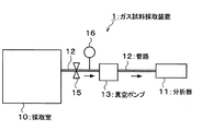
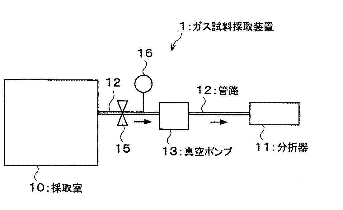
以下,本発明の好ましい実施の形態を図面を参照にして説明する。図1は,本発明の実施の形態にかかるガス試料採取装置1の概略を示す説明図である。
【0010】
採取室10と分析器11が,管路12によって接続されている。管路12の途中には,真空ポンプ13が設けられている。そして,真空ポンプ13を稼動することにより,採取室10内の雰囲気(被分析ガス)を吸引し,管路12を介して,雰囲気を分析器11に送るようになっている。
【0011】
採取室10は,例えば鋼材料などを浸炭処理する真空浸炭炉等である。採取室10内には,炭化水素系ガス(例えばC3H8)などといったガス試料を含んだ雰囲気が所定の流量(例えば1リットル/min)で供給されており,採取室10内では,所定の圧力(例えば10kPa)で浸炭処理を行うことが可能である。
【0012】
分析器11は,管路12を介して送られた採取室10内の雰囲気を分析し,雰囲気中に含まれたガス試料の濃度などを測定する手段であり,例えばFTIR,熱伝導率式分析計,赤外線式分析計,ガスクロマトグラフィーなどである。
【0013】
真空ポンプ13は,採取室10から分析器11に管路12を介して送る雰囲気中に油成分などを混入させないように,オイルフリー型の真空ポンプで構成される。真空ポンプ13は,到達圧力が,採取室10内の雰囲気よりも低い圧力となるものを使用する。例えば,採取室10内の処理圧力が約10kPaの場合であれば,真空ポンプ13の到達圧力は,例えば0.1kPa程度であれば良い。なお,利用する真空ポンプの能力にもよるが,ガス採取対象の圧力(採取室10内の圧力)が1Pa以下になると,採取室10内から排出されるガス流量が少なくなり,分析に必要な流量が得られない可能性がある。
【0014】
採取室10と真空ポンプ13の間において,管路12には,開閉弁15と圧力計16が設けてある。開閉弁15を開閉操作することにより,管路12の連通をON/OFFすることができる。また,圧力計16により,採取室10と真空ポンプ13の間において,管路12内の圧力状態を測定することが可能である。
【0015】
さて,以上のように構成されたガス試料採取装置1において,真空浸炭炉などからなる採取室10内のガス試料を採取して,濃度などを分析する場合,先ず,開閉弁15を閉じた状態で真空ポンプ13を稼動する。そして,採取室10と真空ポンプ13の間において,管路12内の圧力を採取室10内よりも低い状態にする。
【0016】
その後,開閉弁15を開くことにより,採取室10内の雰囲気を真空ポンプ13に引き込む。こうして,採取室10内の雰囲気は吸引採取され,管路12を経て分析器11に送られる。この場合,真空ポンプ13はオイルフリー型であるので,管路12を流れる際に,雰囲気中に油成分などを混入させる心配がない。
【0017】
そして,分析器11では,管路12を経て送られた採取室10内の雰囲気を分析し,雰囲気中に含まれたガス試料の濃度などを測定する。この場合,真空ポンプで吸引採取され,管路12を経て分析器11に送られる採取室10内の雰囲気は,大気圧となった状態で分析器11に供給されるので,分析器11では,圧力調整などを行うことなく,そのままガス試料の分析を行うことができる。
【0018】
このガス試料採取装置1によれば,多数の弁や不活性ガスの注入手段などを設ける必要がなく,簡単な構成で低廉な構成を採用することが可能となる。開閉弁15の開閉と真空ポンプ13の稼動を操作するだけで,容易に採取を行うことができる。
【0019】
以上,本発明の好ましい実施の形態の一例を示したが,本発明はここに例示した形態に限定されない。例えば,採取室は真空浸炭炉に限られず,本発明により,半導体の製造に用いられるエッチング装置やCVD装置などのチャンバー内のガス試料を採取することも可能である。
【0020】
【実施例】
図1で説明したガス試料採取装置により,ガス試料の採取を行い分析した。採取室である真空浸炭炉内において,C3H8を1リットル/minで流し,圧力を10Paに保持した。到達圧力が0.1kPaの真空ポンプを使用して,炉内ガスを本発明に従って採取し,赤外線式採取装置を用いてガス分析した。結果を表1に示す。
【0021】
【表1】
また,本発明のガス試料採取装置と方法について,検証を行った。採取室である真空浸炭炉内において,常温で濃度既知の標準ガスを流し,圧力を63Paに保持した。この炉内ガスを本発明に従って採取し,ガス分析した。測定結果を標準ガス組成と比較して表2に示す。この結果から本発明によって正確に測定できていることが示される。
【0023】
【表2】
【発明の効果】
本発明によれば,多数の弁や不活性ガスの注入手段などを設ける必要がなく,簡単な構成で低廉なガス試料採取装置を提供できる。また,操作も極めて容易である。
【図面の簡単な説明】
【図1】本発明の実施の形態にかかるガス試料採取装置の概略を示す説明図である。
【符号の説明】
1 ガス試料採取装置
10 採取室
11 分析器
12 管路
13 真空ポンプ
15 開閉弁
16 圧力計[0001]
BACKGROUND OF THE INVENTION
The present invention relates to a means for collecting a gas to be analyzed including a gas sample collected in, for example, a vacuum furnace or a vacuum carburizing furnace by sending it to an analyzer.
[0002]
[Prior art]
For example, in a vacuum carburizing furnace for carburizing steel materials, hydrocarbon gases such as methane gas and propane gas are supplied into the furnace under reduced pressure to perform carburizing. In such a vacuum carburizing furnace, in order to control the surface carbon concentration of the steel material to be carburized, the supply amount of hydrocarbon gas is adjusted empirically, and a gas sample is taken from the furnace during the carburizing process. No method has been implemented, and feedback control of carbon potential, such as gas carburization, has not been performed.
[0003]
On the other hand, as a method for collecting gas in a decompression vessel, for example, “Gas sample collecting method and apparatus” disclosed in Japanese Patent Laid-Open No. 5-52719 is disclosed. In Japanese Patent Laid-Open No. 5-52719, an atmosphere is sampled from a decompression chamber containing a gas sample into a T-shaped pipe, and an inert gas is injected into the normal pressure to introduce the gas into an analyzer. It is configured to measure the concentration.
[0004]
[Problems to be solved by the invention]
However, in this Japanese Patent Laid-Open No. 5-52719, the T-shaped pipe is removed one by one and carried to the analyzer, and the sampled atmosphere is introduced into the analyzer. Therefore, a valve that closes the end of the removed pipe is provided. Since it is necessary to provide at each location and a cylinder for injecting an inert gas into the T-shaped pipe is necessary, the apparatus becomes complicated. In addition, the T-shaped pipe must be removed one by one or the T-shaped pipe must be transported to the analyzer, and the operation is complicated. Furthermore, an inert gas to be injected into the T-shaped pipe line is necessary, resulting in an increase in cost.
[0005]
An object of the present invention is to provide means for easily collecting a gas sample with a simple configuration.
[0006]
[Means for Solving the Problems]
To this end, according to the present invention, CO of the gas sample and a vacuum carburizing furnace for collecting the gas sample containing a hydrocarbon gas, CO 2, H 2, analyzer for analyzing the concentration of CH 4 An oil-free vacuum pump is provided in a pipe connecting the two, and a gas sampling device is provided in which a pressure of a gas sampling target in the vacuum carburizing furnace is higher than 1 Pa .
[0007]
In the present invention, a gas to be analyzed including a gas sample is collected from a collection chamber which is a vacuum carburizing furnace by suction with an oil-free vacuum pump. The collected gas to be analyzed is sent to the analyzer and the gas sample is analyzed.
[0008]
According to the present invention, the gas to be analyzed sucked by the oil-free vacuum pump becomes atmospheric pressure and is exhausted to the exhaust side of the vacuum pump. Therefore, the collected gas is directly sent to the analyzer to analyze the gas sample. can do. For this reason, it is not necessary to provide a large number of valves or inert gas injection means, and an inexpensive gas sampling device can be provided with a simple configuration. Also, the analysis operation is extremely easy.
[0009]
DETAILED DESCRIPTION OF THE INVENTION
Hereinafter, preferred embodiments of the present invention will be described with reference to the drawings. FIG. 1 is an explanatory diagram showing an outline of a gas sampling device 1 according to an embodiment of the present invention.
[0010]
The collection chamber 10 and the analyzer 11 are connected by a
[0011]
The sampling chamber 10 is, for example, a vacuum carburizing furnace for carburizing steel material or the like. An atmosphere containing a gas sample such as a hydrocarbon-based gas (for example, C 3 H 8 ) is supplied into the collection chamber 10 at a predetermined flow rate (for example, 1 liter / min). Carburizing treatment can be performed at a pressure of 10 kPa (for example, 10 kPa).
[0012]
The analyzer 11 is a means for analyzing the atmosphere in the collection chamber 10 sent via the
[0013]
The vacuum pump 13 is composed of an oil-free vacuum pump so that oil components and the like are not mixed in the atmosphere sent from the collection chamber 10 to the analyzer 11 via the
[0014]
An open /
[0015]
Now, in the gas sampling device 1 configured as described above, when the gas sample in the sampling chamber 10 composed of a vacuum carburizing furnace or the like is sampled and analyzed for its concentration, the on-off
[0016]
Thereafter, the atmosphere in the collection chamber 10 is drawn into the vacuum pump 13 by opening the on-off
[0017]
Then, the analyzer 11 analyzes the atmosphere in the collection chamber 10 sent via the
[0018]
According to this gas sampling apparatus 1, it is not necessary to provide a large number of valves, inert gas injection means, and the like, and it is possible to adopt a simple configuration and an inexpensive configuration. Sampling can be performed simply by operating the opening / closing of the on-off
[0019]
As mentioned above, although an example of preferable embodiment of this invention was shown, this invention is not limited to the form illustrated here. For example, the collection chamber is not limited to a vacuum carburizing furnace, and according to the present invention, it is also possible to collect a gas sample in a chamber such as an etching apparatus or a CVD apparatus used for manufacturing a semiconductor.
[0020]
【Example】
A gas sample was collected and analyzed by the gas sampler described in FIG. In a vacuum carburizing furnace as a sampling chamber, C 3 H 8 was flowed at 1 liter / min and the pressure was maintained at 10 Pa. Using a vacuum pump with an ultimate pressure of 0.1 kPa, the in-furnace gas was sampled according to the present invention and analyzed using an infrared sampling device. The results are shown in Table 1.
[0021]
[Table 1]
In addition, the gas sampling apparatus and method of the present invention were verified. In a vacuum carburizing furnace, which is a sampling chamber, a standard gas with a known concentration was allowed to flow at room temperature, and the pressure was maintained at 63 Pa. This furnace gas was collected according to the present invention and analyzed for gas. The measurement results are shown in Table 2 in comparison with the standard gas composition. From this result, it is shown that the present invention can be measured accurately.
[0023]
[Table 2]
【The invention's effect】
According to the present invention, it is not necessary to provide a large number of valves and inert gas injection means, and an inexpensive gas sampling apparatus can be provided with a simple configuration. In addition, the operation is extremely easy.
[Brief description of the drawings]
FIG. 1 is an explanatory diagram showing an outline of a gas sampling apparatus according to an embodiment of the present invention.
[Explanation of symbols]
DESCRIPTION OF SYMBOLS 1 Gas sampling device 10 Sampling chamber 11
Claims (4)
Priority Applications (1)
| Application Number | Priority Date | Filing Date | Title |
|---|---|---|---|
| JP2001246086A JP4635227B2 (en) | 2001-08-14 | 2001-08-14 | Gas sampling apparatus and method |
Applications Claiming Priority (1)
| Application Number | Priority Date | Filing Date | Title |
|---|---|---|---|
| JP2001246086A JP4635227B2 (en) | 2001-08-14 | 2001-08-14 | Gas sampling apparatus and method |
Publications (2)
| Publication Number | Publication Date |
|---|---|
| JP2003057155A JP2003057155A (en) | 2003-02-26 |
| JP4635227B2 true JP4635227B2 (en) | 2011-02-23 |
Family
ID=19075716
Family Applications (1)
| Application Number | Title | Priority Date | Filing Date |
|---|---|---|---|
| JP2001246086A Expired - Lifetime JP4635227B2 (en) | 2001-08-14 | 2001-08-14 | Gas sampling apparatus and method |
Country Status (1)
| Country | Link |
|---|---|
| JP (1) | JP4635227B2 (en) |
Families Citing this family (2)
| Publication number | Priority date | Publication date | Assignee | Title |
|---|---|---|---|---|
| JP5562539B2 (en) * | 2008-08-21 | 2014-07-30 | 矢崎総業株式会社 | Concentration measuring device |
| JP6333714B2 (en) * | 2014-12-15 | 2018-05-30 | 岩谷産業株式会社 | Sampling apparatus and sampling method |
Family Cites Families (5)
| Publication number | Priority date | Publication date | Assignee | Title |
|---|---|---|---|---|
| JPH0552719A (en) * | 1991-08-27 | 1993-03-02 | Shimadzu Corp | Gas sampling method and apparatus |
| JP2971646B2 (en) * | 1991-11-15 | 1999-11-08 | 日本碍子株式会社 | Gas analyzer |
| US5271264A (en) * | 1991-11-27 | 1993-12-21 | Applied Materials, Inc. | Method of in-situ particle monitoring in vacuum systems |
| JPH05240839A (en) * | 1992-02-27 | 1993-09-21 | Shimadzu Corp | Gas analyzer |
| JP3089120B2 (en) * | 1992-11-13 | 2000-09-18 | 日本原子力研究所 | Gas component analyzer |
-
2001
- 2001-08-14 JP JP2001246086A patent/JP4635227B2/en not_active Expired - Lifetime
Also Published As
| Publication number | Publication date |
|---|---|
| JP2003057155A (en) | 2003-02-26 |
Similar Documents
| Publication | Publication Date | Title |
|---|---|---|
| CN106501125B (en) | Gas adsorption and desorption test device and test method | |
| US6516654B2 (en) | Apparatus and method for analyzing particulate matter in gas and apparatus and method for carbon differentiating | |
| GR1006900B (en) | Diluter for exhaust gas sampling and method therefor. | |
| JP4635227B2 (en) | Gas sampling apparatus and method | |
| JPH05256748A (en) | Method and apparatus for analyzing organic material using portable structure | |
| US7977113B2 (en) | Biological agent detector method | |
| EP0877246A2 (en) | In situ monitoring of contaminants in semiconductor processing chambers | |
| US7863055B2 (en) | Sampling system for introduction of high boiling point streams at low temperature | |
| JP3779908B2 (en) | Exhaust gas measuring device and exhaust gas sampling device | |
| CN211627463U (en) | Online thermal desorption gas circuit system | |
| CN101495849B (en) | Methods and apparatuses for insitu analysis of gases in electronic device fabrication systems | |
| CN121253747A (en) | Device for quantitatively analyzing oxygen generated in battery material | |
| US20070240488A1 (en) | Molten Metal Gas Sampling | |
| ATE508355T1 (en) | GAS SAMPLING AND ANALYSIS SYSTEM | |
| JPH10104133A (en) | Gas sampling equipment | |
| CN209356459U (en) | A pretreatment device for VOC component detection | |
| CN114375395A (en) | Gas analysis method and gas analysis device | |
| JP2005091297A (en) | Total hydrocarbon analysis system | |
| CN118731239B (en) | A synchronous monitoring system for soil greenhouse gas and nitrogen oxide fluxes | |
| JP2006132941A (en) | Gas sampling apparatus and gas sampling method | |
| JP3992121B2 (en) | Exhaust gas dilution sampling device | |
| JP2000074798A (en) | Gas analyzer | |
| CN117907530A (en) | Gas detection device and detection method | |
| JPH05215721A (en) | Gas analyzer | |
| JPH0552719A (en) | Gas sampling method and apparatus |
Legal Events
| Date | Code | Title | Description |
|---|---|---|---|
| A621 | Written request for application examination |
Free format text: JAPANESE INTERMEDIATE CODE: A621 Effective date: 20080529 |
|
| A977 | Report on retrieval |
Free format text: JAPANESE INTERMEDIATE CODE: A971007 Effective date: 20100715 |
|
| A131 | Notification of reasons for refusal |
Free format text: JAPANESE INTERMEDIATE CODE: A131 Effective date: 20100727 |
|
| A521 | Request for written amendment filed |
Free format text: JAPANESE INTERMEDIATE CODE: A523 Effective date: 20100927 |
|
| TRDD | Decision of grant or rejection written | ||
| A01 | Written decision to grant a patent or to grant a registration (utility model) |
Free format text: JAPANESE INTERMEDIATE CODE: A01 Effective date: 20101019 |
|
| A01 | Written decision to grant a patent or to grant a registration (utility model) |
Free format text: JAPANESE INTERMEDIATE CODE: A01 |
|
| A711 | Notification of change in applicant |
Free format text: JAPANESE INTERMEDIATE CODE: A711 Effective date: 20101101 |
|
| A61 | First payment of annual fees (during grant procedure) |
Free format text: JAPANESE INTERMEDIATE CODE: A61 Effective date: 20101101 |
|
| A521 | Request for written amendment filed |
Free format text: JAPANESE INTERMEDIATE CODE: A821 Effective date: 20101101 |
|
| FPAY | Renewal fee payment (event date is renewal date of database) |
Free format text: PAYMENT UNTIL: 20131203 Year of fee payment: 3 |
|
| R150 | Certificate of patent or registration of utility model |
Ref document number: 4635227 Country of ref document: JP Free format text: JAPANESE INTERMEDIATE CODE: R150 Free format text: JAPANESE INTERMEDIATE CODE: R150 |
|
| R250 | Receipt of annual fees |
Free format text: JAPANESE INTERMEDIATE CODE: R250 |
|
| R250 | Receipt of annual fees |
Free format text: JAPANESE INTERMEDIATE CODE: R250 |
|
| R250 | Receipt of annual fees |
Free format text: JAPANESE INTERMEDIATE CODE: R250 |
|
| R250 | Receipt of annual fees |
Free format text: JAPANESE INTERMEDIATE CODE: R250 |
|
| R250 | Receipt of annual fees |
Free format text: JAPANESE INTERMEDIATE CODE: R250 |
|
| R250 | Receipt of annual fees |
Free format text: JAPANESE INTERMEDIATE CODE: R250 |
|
| R250 | Receipt of annual fees |
Free format text: JAPANESE INTERMEDIATE CODE: R250 |
|
| R250 | Receipt of annual fees |
Free format text: JAPANESE INTERMEDIATE CODE: R250 |
|
| EXPY | Cancellation because of completion of term |