JP4635184B2 - Zinc oxide phosphor, method for producing the same and light emitting device - Google Patents
Zinc oxide phosphor, method for producing the same and light emitting device Download PDFInfo
- Publication number
- JP4635184B2 JP4635184B2 JP2005505959A JP2005505959A JP4635184B2 JP 4635184 B2 JP4635184 B2 JP 4635184B2 JP 2005505959 A JP2005505959 A JP 2005505959A JP 2005505959 A JP2005505959 A JP 2005505959A JP 4635184 B2 JP4635184 B2 JP 4635184B2
- Authority
- JP
- Japan
- Prior art keywords
- zinc oxide
- phosphor
- light
- emitting device
- hydrogen
- Prior art date
- Legal status (The legal status is an assumption and is not a legal conclusion. Google has not performed a legal analysis and makes no representation as to the accuracy of the status listed.)
- Expired - Fee Related
Links
Images


Classifications
-
- C—CHEMISTRY; METALLURGY
- C09—DYES; PAINTS; POLISHES; NATURAL RESINS; ADHESIVES; COMPOSITIONS NOT OTHERWISE PROVIDED FOR; APPLICATIONS OF MATERIALS NOT OTHERWISE PROVIDED FOR
- C09K—MATERIALS FOR MISCELLANEOUS APPLICATIONS, NOT PROVIDED FOR ELSEWHERE
- C09K11/00—Luminescent materials, e.g. electroluminescent or chemiluminescent
- C09K11/08—Luminescent materials, e.g. electroluminescent or chemiluminescent containing inorganic luminescent materials
- C09K11/54—Luminescent materials, e.g. electroluminescent or chemiluminescent containing inorganic luminescent materials containing zinc or cadmium
-
- C—CHEMISTRY; METALLURGY
- C09—DYES; PAINTS; POLISHES; NATURAL RESINS; ADHESIVES; COMPOSITIONS NOT OTHERWISE PROVIDED FOR; APPLICATIONS OF MATERIALS NOT OTHERWISE PROVIDED FOR
- C09K—MATERIALS FOR MISCELLANEOUS APPLICATIONS, NOT PROVIDED FOR ELSEWHERE
- C09K11/00—Luminescent materials, e.g. electroluminescent or chemiluminescent
- C09K11/08—Luminescent materials, e.g. electroluminescent or chemiluminescent containing inorganic luminescent materials
- C09K11/62—Luminescent materials, e.g. electroluminescent or chemiluminescent containing inorganic luminescent materials containing gallium, indium or thallium
- C09K11/621—Chalcogenides
- C09K11/623—Chalcogenides with zinc or cadmium
-
- C—CHEMISTRY; METALLURGY
- C09—DYES; PAINTS; POLISHES; NATURAL RESINS; ADHESIVES; COMPOSITIONS NOT OTHERWISE PROVIDED FOR; APPLICATIONS OF MATERIALS NOT OTHERWISE PROVIDED FOR
- C09K—MATERIALS FOR MISCELLANEOUS APPLICATIONS, NOT PROVIDED FOR ELSEWHERE
- C09K11/00—Luminescent materials, e.g. electroluminescent or chemiluminescent
- C09K11/08—Luminescent materials, e.g. electroluminescent or chemiluminescent containing inorganic luminescent materials
-
- H—ELECTRICITY
- H01—ELECTRIC ELEMENTS
- H01J—ELECTRIC DISCHARGE TUBES OR DISCHARGE LAMPS
- H01J63/00—Cathode-ray or electron-stream lamps
- H01J63/02—Details, e.g. electrode, gas filling, shape of vessel
- H01J63/04—Vessels provided with luminescent coatings; Selection of materials for the coatings
-
- Y—GENERAL TAGGING OF NEW TECHNOLOGICAL DEVELOPMENTS; GENERAL TAGGING OF CROSS-SECTIONAL TECHNOLOGIES SPANNING OVER SEVERAL SECTIONS OF THE IPC; TECHNICAL SUBJECTS COVERED BY FORMER USPC CROSS-REFERENCE ART COLLECTIONS [XRACs] AND DIGESTS
- Y10—TECHNICAL SUBJECTS COVERED BY FORMER USPC
- Y10T—TECHNICAL SUBJECTS COVERED BY FORMER US CLASSIFICATION
- Y10T428/00—Stock material or miscellaneous articles
- Y10T428/29—Coated or structually defined flake, particle, cell, strand, strand portion, rod, filament, macroscopic fiber or mass thereof
- Y10T428/2982—Particulate matter [e.g., sphere, flake, etc.]
- Y10T428/2991—Coated
Landscapes
- Chemical & Material Sciences (AREA)
- Inorganic Chemistry (AREA)
- Engineering & Computer Science (AREA)
- Materials Engineering (AREA)
- Organic Chemistry (AREA)
- Luminescent Compositions (AREA)
- Vessels And Coating Films For Discharge Lamps (AREA)
Description
【技術分野】
【0001】
本発明は、比較的安価であり、資源的にも安定して得られる酸化亜鉛を利用する蛍光塗料、又は発光装置に利用されるブロードな可視発光スペクトルを与えることを特徴とする酸化亜鉛蛍光体とその製造法及び該酸化亜鉛蛍光体を用いる発光装置に関する。
【背景技術】
【0002】
酸化亜鉛の特性制御は、添加物の添加と熱処理によって実現される。クレーガ・フィンクの欠陥方程式では、例えば、下記の式1及び式2のようにして欠陥生成による導電率の付与が記述される。
【0003】
【化1】
【化2】
![]()
これまで、こうして導入された欠陥が酸化亜鉛の発光に関与していると考えられており、既に開発・実用化がなされている青緑色の発光を与える酸化亜鉛蛍光体は、式1、又は式2の化学反応で合成される欠陥を含んだ酸化亜鉛、言い換えると、化学式としてZn1+xO、又はZnO1-xで与えられるような組成物であるとされている。例えば、特許文献1に見られるように、酸素分圧の低い雰囲気下で亜鉛を含む無機原料を熱処理することによってその製造が実施されている。
【0006】
酸化亜鉛に対する不純物添加による特性制御は、III族元素であるアルミニウム、インジウム、ガリウムのいずれか、又はアルカリ金属元素であるナトリウム、リチウムなどを加えることによって実現される。これらの添加物の添加は、式3、式4のように記述され、式3は、Xで示されたIII族元素の添加による導電性の付与、式4は、Zで示されたアルカリ金属元素の添加による導電性の抑制を示す。
【0007】
【化3】
【化4】
従来、ZnOへの添加物の効果はドナー、又はアクセプターのいずれかを導入するという技術が一般的であり、緑色の発光を与える酸化亜鉛基組成物においても、原理的には、Zn1+xO、又はZnO1-xで与えられるような組成物、すなわち、ドナーを導入した酸化亜鉛において実現されているとされる。
【0010】
これに対して、本発明は、酸化亜鉛中でドナー準位の形成をもたらすIII族元素とアクセプター準位の形成をもたらすアルカリ金属元素を同時に添加してその発光特性を制御するので、従来技術と異なる。
【0011】
黄色の発色を与える酸化亜鉛塗料に関して、特許文献2がある。この特許文献2に記載された発明では、日光や、一般的な照明に代表される白色光で照らした際に、黄色に見える塗料の組成及びその製造法が示されている。すなわち、黄色の反射スペクトルを与える酸化亜鉛基組成物に関する発明である。しかし、特許文献2は、黄色塗料に粒子線や電磁波を照射した場合の発光について、何ら示すものではなく、同発明と本発明は、その目的・効果を異にするものであり、黄色みを帯びた発光は、特許文献2に開示されている技術によっては達成されない。
【0012】
黄色みを帯びた発光を与える蛍光体に、セリウムを添加したイットリウムアルミニウムガーネットが挙げられる。この蛍光体は、シンチレーター材料として利用されている。例えば、非特許文献1にその発光の様子が示されている。近年、当該蛍光体は、窒化物半導体LEDと組み合わせることによって、白色発光する半導体装置を製造する際にも利用されている。
【0013】
先に示した、Zn1+xO、又はZnO1-x緑色の発光と異なり、添加物によって可視発光を生じさせる方法がある。それは、ランタニド元素を添加することによって可視発光を付活(activate)するものであり、特許文献3にその組成が示されている。当該発明による酸化亜鉛基組成物は、ランタニド元素の輝線(emission line)を使った可視発光であり、特定の波長のみを発することを特徴とする。いわゆる白熱灯に代表される、ブロードな発光バンドを有し、連続的な発光スペクトルを生じさせる酸化亜鉛基組成物の製造法ではない。したがって、本発明の目的とそこから得られる効果は、特許文献3に開示された技術によっては達せられない。
【先行技術文献】
【0014】
【特許文献】
【特許文献1】
特開平06−093259号公報
【特許文献2】
特公平06−070190号公報
【特許文献3】
特開平08−236275号公報
【0015】
【非特許文献】
【非特許文献1】
T.Tamura,T.Setomoto,and T.Taguchi,Journal of Luminescence誌,87−89巻,1180ページ,(2000年)
【発明の開示】
【発明が解決しようとする課題】
【0016】
本発明で着目する酸化亜鉛基組成物の発光は物理学的には既に検討が行われていた課題である。例えば、SchermelとTwingel:Solid State Communication誌,第8巻,1559ページ,1970年が示しているように、極低温の状態においては、黄色の発光が酸化亜鉛基組成物から得られている。
【0017】
しかし、これまで、このような酸化亜鉛基組成物の有効な工業的製造法やその発光効率を制御するための化学組成が示されておらず、その製造法及び材料として工業利用に供されるための化学組成は不明なままであった。さらに、ブロードな発光スペクトルを実現することによる黄色みを帯びた発光という観点での工業的開発は達成されていなかった。
【0018】
本発明の課題は、少なくとも当該組成物のバンドギャップを越えるエネルギーを有する、紫外線とそれよりも短波長の電磁波、又は電子線によってZnO中に電子と正孔を励起した際に、その室温での発光スペクトルの強度の最強値が波長550〜650ナノメーターの範囲において観測され、また、短波長側の裾が波長400ナノメーター以下にまで及び、かつ、長波長側の裾が800ナノメーター以上の長波長に及ぶ連続したスペクトルとなることを特徴とする酸化亜鉛蛍光体の実現である。すなわち、当該発光を実現するに有効なエネルギー準位を酸化亜鉛基組成物に導入することである。
【0019】
また、酸化亜鉛に発光機能を付活する場合、熱処理、又は添加物を加えることによって、電荷補償(electric charge compensation)のための欠陥が形成される。欠陥や添加物が酸化亜鉛の発光に与える影響には、2つがあり、一方は、その欠陥や添加物が原因となった発光を与える場合であり、この発光を与える電子遷移(electric transition)は、輻射遷移(radiative transition)と呼ばれる。他方、酸化亜鉛中に励起された電子・正孔対が光を発することなく、熱としてエネルギーを散逸してしまう過程も可能であり、こうした電子遷移を非輻射遷移と呼ぶ。
【0020】
蛍光体としての機能を高めるためには、有用な輻射遷移を与える欠陥を不活性化し、励起された電子・正孔対が有用な輻射遷移によって再結合する確率を高める必要がある。すなわち、本発明が解決するべき課題は、非輻射遷移の確率を低減して、発光効率を高めることである。
【課題を解決するための手段】
【0021】
純粋な酸化亜鉛は、約3.3電子ボルトのバンドギャップを持つ半導体であり、純粋な酸化亜鉛は約380ナノメーターの紫外線発光を与える。また、欠陥を導入することにより、約520ナノメーターに発光強度のピークを持つ青緑色の発光を与える。こうした特徴を持つ酸化亜鉛から発光を得るためには、バンドギャップ内に、さらに、輻射遷移を与える準位を導入しなければならない。
【0022】
一般的な酸化、又は還元的な雰囲気中での熱処理では、先の緑色発光の欠陥のみが導入されるため、何らかの添加物を加えて、他の欠陥を導入しなければならない。また、そうして導入された欠陥が、少なくともバンドギャップを越えるエネルギーを持つ粒子線や電磁波による励起に対して、青色でも緑色でもない、黄色みを帯びた可視発光を与えるに適当なエネルギー状態をもっている必要がある。
【0023】
本発明者らは、ドナー・アクセプター対による発光、すなわち、ドナーが持つ電子とアクセプターが持つ正孔との結合による発光を実現すべく研究を進めた結果、アルミニウム、ガリウム、インジウムのうちの少なくとも1種と、リチウム、ナトリウムのうちの少なくとも一種の計2種以上の添加物を含む酸化亜鉛であって、紫外線とそれよりも短波長の電磁波、又は電子線によって励起した際に、その室温での発光スペクトルの強度の最強値が波長550〜650ナノメーターの範囲において観測され、また、短波長側の裾が波長400ナノメーター以下にまで及び、かつ、長波長側の裾が800ナノメーター以上の長波長に及ぶ連続したスペクトルとなることを特徴とする酸化亜鉛蛍光体を見出した。
【0024】
特に、酸化亜鉛蛍光体であって、CIE1964表色系(color specification system)でx=0.40から0.47の範囲であり、かつ、y=0.44から0.47に対応する黄色みを帯びた色であることを特徴する酸化亜鉛蛍光体は、室温で黄白色の発光を与える蛍光体となる。
【0025】
ここで、表色系の座標値に広がりがあるのは、本発明による蛍光体の発光には、残光(afterglow)特性があり、その励起方法、又は励起が連続的であるかパルス的であるか、また、その残光が顕著に見られるような励起方法であるか否か、という各条件によって、発光の現れ方に、幅が出ることを意味している。
【0026】
蛍光体をより有用なものとするには、先に述べた非輻射遷移の確率を低減する必要がある。非輻射遷移の確率を低減する方法は、例えば特開平10−245550号公報に開示されているが、同方法にあっては、非輻射遷移だけではなく、欠陥が関与した輻射遷移もあわせて不活性化することによって、高い紫外線発光効率を得ようとするものである。
【0027】
これに対して、本発明では、酸化亜鉛蛍光体に導入する水素の濃度を調整することによって、酸化亜鉛蛍光体中の有用な可視発光を与える欠陥・不純物のみを活性化し、非輻射遷移を与える可視発光を不活性化することで、その蛍光体としての機能を向上させる。
【0028】
その非輻射遷移の確率を低減した酸化亜鉛蛍光体として、可視光の発光を特徴とする酸化亜鉛蛍光体に対し、特に、その蛍光体中に形成された非輻射遷移の原因となる欠陥を不活性化し、かつ、輻射遷移をもたらす欠陥を不活性化するには至らないように濃度を調整された水素が固溶した表面層を有すること、又は結晶粒子全体に亘ってその蛍光体中に形成された非輻射遷移の原因となる欠陥を不活性化し、かつ、輻射遷移をもたらす欠陥を不活性化するには至らないように濃度を調整された水素を含むことを特徴とする酸化亜鉛蛍光体が利用可能である。
【0029】
ここで、水素を添加する方法については、特に限定する必要はなく、酸化亜鉛中に水素を導入できる方法であればよい。しかし、高温の水素ガス中での処理で水素を導入しようとすると、酸素分圧が低い水素ガス雰囲気が原因となり、酸化亜鉛の昇華や添加物組成のずれが生じる恐れがある。そのため、水素プラズマ、又は水素ラジカルという活性化された水素に当該蛍光体を露出して水素を導入することが有効であり、プラズマ発生装置を用いることが可能である。このようなプラズマ発生装置は公知である(例えば、日本特許第2920207号公報)。
【0030】
さらに、本発明の目的は、酸化亜鉛蛍光体を励起し、そこから光を取り出すための装置を提供することである。本発明が与える酸化亜鉛蛍光体は、酸化亜鉛のバンドギャップエネルギーを越える電磁波や粒子線によって発光を得ることである。
【0031】
その方法として、(1)当該酸化亜鉛蛍光体に波長が375nm以下である電磁波を照射することによってその発光を励起すること、(2)当該酸化亜鉛蛍光体に電子線を照射することによって当該蛍光体の発光を励起すること、のいずれかによって、可視光を得る装置が得られる。
【0032】
さらに、この可視光を得る装置を、所望のパターンに配列することによって、情報、画像を表示するためのディスプレーパネルを得ることができる。
【図面の簡単な説明】
【0033】
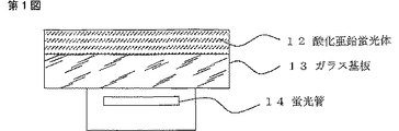
【図1】第1図は、本発明の紫外線励起による発光装置の概略図である。
【図2】第2図は、本発明の電子線励起による発光装置の概略図である。
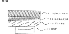
【図3】第3図は、本発明の紫外線励起による発光装置にカラーフィルターを取り付けた態様を示す概略図である。
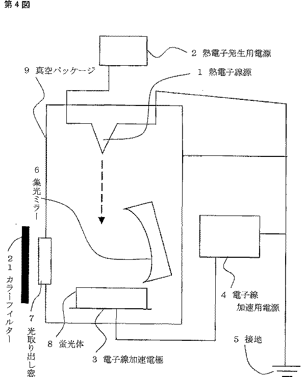
【図4】第4図は、本発明の電子線励起による発光装置にカラーフィルターを取り付けた態様を示す概略図である。
【図5】第5図は、本発明の方法による水素を添加する処理前の酸化亜鉛蛍光体であって、参考例1で製造された蛍光体と比較例(従来品)の蛍光体の電子線励起による発光スペクトルである。
【図6】第6図は、参考例1で製造された蛍光体と、実施例1で製造された、参考例1の蛍光体に水素を添加した蛍光体の電子線励起による発光スペクトルである。
【図7】第7図は、本発明の方法による水素を添加する処理前の酸化亜鉛蛍光体であって、参考例1で製造された蛍光体と、参考例2で製造された蛍光体の電子線励起による発光スペクトルである。
【発明を実施するための最良の形態】
【0034】
(1)酸化亜鉛蛍光体の組成と発光
本発明の対象となる酸化亜鉛蛍光体は、少なくとも当該組成物のバンドギャップエネルギーを越えるエネルギーを持つ粒子線、又は電磁波による励起に対して、目視によって、黄色みを帯びた発光を与えることが認められる、すなわち、その室温での発光スペクトルの強度の最強値が波長550〜650ナノメーターの範囲において観測され、また、短波長側の裾が波長400ナノメーター以下にまで及び、かつ、長波長側の裾が800ナノメーター以上の長波長に及ぶ連続したスペクトルとなることを特徴とする酸化亜鉛蛍光体であって、その製造法の如何を問わず、酸化亜鉛を主成分とし、これにアルミニウム、ガリウム、インジウムのうちの少なくとも1種と、リチウム、ナトリウムのうちの少なくとも一種の計2種以上の添加物を含む酸化亜鉛であることを特徴する酸化亜鉛基組成物である。
【0035】
また、本発明の対象となる酸化亜鉛蛍光体は、前記酸化亜鉛基組成物であって、その発光効率をさらに高めるために、その蛍光体中に形成された非輻射遷移の原因となる欠陥を不活性化し、かつ、輻射遷移をもたらす欠陥を不活性化するには至らないように濃度を調整された水素が固溶した表面層を有すること、又は粒子全体に亘ってその蛍光体中に形成された非輻射遷移の原因となる欠陥を不活性化し、かつ、輻射遷移をもたらす欠陥を不活性化するには至らないように濃度を調整された水素を含むことを特徴とする酸化亜鉛蛍光体である。
【0036】
また、本発明の対象となる酸化亜鉛蛍光体は、前記酸化亜鉛基組成物であって、その組成によって、目視した際の発色が、CIE1964表色系でx=0.40から0.47の範囲であり、かつ、y=0.44から0.47に対応する黄色みを帯びた色であることを特徴する酸化亜鉛蛍光体である。
【0037】
さらに、本発明の対象となる酸化亜鉛蛍光体は、前記酸化亜鉛基組成物であって、その組成によって、目視した際の発色が、CIE1964表色系でx=0.40から0.47の範囲であり、かつ、y=0.44から0.47に対応する黄色みを帯びた色であることを特徴する酸化亜鉛蛍光体であり、かつ、その発光効率をさらに高めるために、その蛍光体中に形成された非輻射遷移の原因となる欠陥を不活性化し、かつ、輻射遷移をもたらす欠陥を不活性化するには至らないように濃度を調整された水素が固溶した表面層を有すること、又は粒子全体に亘ってその蛍光体中に形成された非輻射遷移の原因となる欠陥を不活性化し、かつ、輻射遷移をもたらす欠陥を不活性化するには至らないように濃度を調整された水素を含むことを特徴とする酸化亜鉛蛍光体である。
【0038】
ここで、本発明の酸化亜鉛蛍光体を製造する際に用いる酸化亜鉛の組成は、アルミニウム、ガリウム、インジウムを含む無機塩又は酸化物のうちの少なくとも1種と、リチウム、ナトリウムを含む無機塩又は酸化物のうちの少なくとも一種の計2種以上の添加物を加えた酸化亜鉛である。
【0039】
酸化亜鉛中のこれらの添加物濃度は、その固溶限界によって規定される。一方、酸化亜鉛中のこれらの添加物の固溶限界は、その酸化亜鉛蛍光体がおかれる環境、すなわち、固溶体を製造する際の熱処理温度、酸素分圧によって、変化する。
【0040】
発光波長を制御するための不純物の添加量の最大値は固溶限界で規定される。固溶限界は、材料を合成する際の温度と酸素分圧に依存するため一概には規定できないが、アルミニウム、インジウム、ガリウムの濃度として最大値は3000PPM位、ナトリウム、リチウムについては、1000ppm位になる。また、ある程度高い発光効率を得る最小限度については、アルミニウム、ガリウム、インジウムに関しては500ppm以上、リチウム、ナトリウムについては、100ppm以上が適当である。これらの不純物が発光の元になるので、濃度が高い方が良く光ることになるが、電子線を照射して発光させる方法では、電気抵抗が高くなりすぎた場合に、発光効率が落ちてしまうことを考慮して、リチウムとナトリウムの添加量を調整する必要がある。
【0041】
また、固溶体を製造する工程中において熱を加えた場合、揮発しやすいことを特徴とするリチウムやナトリウムが当該蛍光体に固溶せず、気化して損なわれる場合がある。そのため、固溶体を製造するにあたっては、固溶体を製造する際の熱処理温度、雰囲気、さらには、固溶体を製造する工程中における原料の気化蒸発を加味して、固溶体を製造するための初期組成を決定する必要がある。
【0042】
本発明は、発光スペクトルの強度の最強値が波長550〜650ナノメーターの範囲において観測され、また、短波長側の裾が波長400ナノメーター以下にまで及び、かつ、長波長側の裾が800ナノメーター以上の長波長に及ぶ連続したスペクトルとなることを特徴とする酸化亜鉛蛍光体を得るために、アルミニウム、ガリウム、インジウムのうちの少なくとも1種と、リチウム、ナトリウムのうちの少なくとも一種の計2種以上の添加物を含む酸化亜鉛を得ることが有効であることを示すものであり、その発光効率に対する最適条件は、その製造時に最適化する必要がある。
【0043】
(2)組成物の簡便な製造方法
本発明が対象とする、紫外線とそれよりも短波長の電磁波、又は電子線によって励起した際に、その室温での発光スペクトルの強度の最強値が波長550〜650ナノメーターの範囲において観測され、また、短波長側の裾が波長400ナノメーター以下にまで及び、かつ、長波長側の裾が800ナノメーター以上の長波長に及ぶ連続したスペクトルとなることを特徴とする酸化亜鉛蛍光体の簡便な製造法の1つは、酸化亜鉛を主成分とし、これにアクセプター準位の形成をもたらすアルカリ金属元素の少なくとも1種と、ドナー準位の形成をもたらすIII族元素の少なくとも1種のあわせて2種以上の副成分を含むことを特徴する酸化亜鉛基組成物を製造することである。
【0044】
その製造方法の1つは、特に、アルミニウム、ガリウム、インジウムを含む無機塩又は酸化物のうちの少なくとも1種と、リチウム、ナトリウムを含む無機塩又は酸化物のうちの少なくとも一種の計2種以上の添加物を加えた酸化亜鉛を添加物が酸化亜鉛結晶中に固溶するに足る高温で熱処理して製造することを特徴とするという方法である。
【0045】
アルカリ金属の原料としては、酸化物(Li2O,Na2O)、炭酸塩(Li2CO3,Na2CO3)、硝酸塩(Li2NO3,Na2NO3)、水酸化物(LiOH,NaOH)、金属(Li,Na)等を用いることが可能であるが、一般にその吸湿性や反応性が原因となって正確な秤量や安全な取扱が難しくなるため、炭酸塩の形態を持つ化合物を利用するのが簡便である。
【0046】
また、III族元素の原料としては、酸化物(Al2O3,Ga2O3,In2O3など)を用いることが簡便である。弗化物等の利用も原理的には可能であるが、分解して発生するフッ素などが酸化亜鉛基組成物の副成分として熱処理後も残存してしまう恐れがあるため、固形のIII族元素の原料には、酸化物を使用することが望ましい。また、添加する原料の反応性に応じて、添加したLi2CO3やAl2O3等の原料が主成分である酸化亜鉛と十分に反応し、酸化亜鉛基組成物中に、発光に寄与するドナー準位とアクセプター準位が形成されるに足る温度で熱処理しなければならない。
【0047】
例えば、一般的に市販されている粉末試薬のLi2CO3と一般的に市販されている粉末試薬のAl2O3を一般的に市販されている粉末試薬の酸化亜鉛に添加して熱処理する場合、特にその加熱機構を限定しない熱処理装置において、800℃〜1100℃の範囲で3時間から12時間の熱処理を施すことが望ましい。しかし、熱処理条件は、その添加物原料、及び、主成分である酸化亜鉛原料の粉体粒子径などに依存するため、製造にあたっては、使用する原料の形態によって、熱処理温度と熱処理時間を調整する必要がある。
【0048】
熱処理雰囲気は、特に限定しないが、電気的に低い抵抗を示す発光材料を得るという目的以外の場合、酸素雰囲気中で熱処理することが望ましい。特に、アルカリ金属元素は、蒸気圧が高く、特に温度を上げた場合に蒸発して失われやすいため、添加物と主成分の酸化亜鉛が反応する温度であって、かつ、アルカリ金属の蒸発が顕著にならない温度にいったん加熱して、反応を開始させて仮焼した後に、さらに高温で熱処理するという方法をとっても、差し支えない。
【0049】
この仮焼は、用いる原料によって異なり、分解温度が高い原料を用いざるを得ない場合、より高温でこの仮焼を実施しなければならない。例えば、酸化ガリウムと炭酸リチウムを用いた場合の仮焼温度は800℃から1000℃とするのが、望ましい。
【0050】
また、熱処理に際し、過剰な高温、又は過剰に低い酸素分圧において処理を行った場合、主成分である酸化亜鉛、又は副成分であるアルカリ金属元素やIII族元素の蒸発が顕著になり、本発明による酸化亜鉛基組成物からなる発光材料が所望の特性を持たなくなる恐れがあるため、熱処理の温度、雰囲気は、こうした蒸発による顕著な組成変化が起こらない条件下で行うことが望ましい。しかし、ここに示した方法は、簡便な方法の例であって、この方法を実施するか否かは、本発明において必ずしも必要な事項ではない。
【0051】
上記以外の簡便な製造方法のうちの1つは、酸化亜鉛粉末に対して、酸化亜鉛中にアクセプター準位の形成をもたらすアルカリ金属元素の少なくとも1種を含む溶液(LiCl,NaCl水溶液やそれをアルコール類で希釈した溶液など)と、酸化亜鉛中にドナー準位の形成をもたらすIII族元素の少なくとも1種を含む溶液(Al(NO3)3水溶液やそれをアルコール類で希釈した溶液など)を加えた後に、乾燥して混合、又は混練して乾燥という処置を加えることによって得た混合物に熱処理を施して反応させるという方法である。
【0052】
混練して乾燥、又は乾燥して混合の過程は、特にその前後をこだわらないが、添加する溶液の量によって適宜、その順番を変更しても、製造工程全体に与える影響は無視できる。乾燥と混合を同時に行うこともあり得る。乾燥の条件は、乾燥の後に行う熱処理において、揮発成分(水分など)の蒸発が、その反応、製造物の回収の妨げとならない程度になされていれば、特に、その乾燥工程のための温度、雰囲気は限定しない。結果として、主成分と添加したアルカリ金属及びIII族元素が良く混合された状態を達成できる手法であれば、特に製造物の特性に顕著な違いを与えるものではない。
【0053】
また、熱処理については、リチウムやアルミニウム等の副成分が主成分である酸化亜鉛と十分に反応し、酸化亜鉛基組成物中に、発光に寄与するドナー準位とアクセプター準位が形成されるに足る温度で熱処理しなければならない。例えば、塩化リチウム水溶液と硝酸アルミニウムを一般的に市販されている粉末試薬の酸化亜鉛に添加して熱処理する場合、特にその加熱機構を限定しない熱処理装置において、800℃〜1100℃の範囲で3時間から12時間の熱処理を施すことが望ましい。
【0054】
しかし、熱処理条件は、その添加物原料及び主成分である酸化亜鉛原料の粉体粒子径などに依存するため、製造にあたっては、使用する原料の形態によって、熱処理温度と熱処理時間を調整する必要がある。熱処理雰囲気は、特に限定しないが、電気的に低い抵抗を示す発光材料を得るという目的以外の場合、酸素雰囲気中で熱処理することが望ましい。特に、アルカリ金属元素は、蒸気圧が高く、特に温度を上げた場合に蒸発して失われやすいため、添加物と主成分の酸化亜鉛が反応する温度であって、かつ、アルカリ金属の蒸発が顕著にならない温度にいったん加熱して、反応を開始させた後に、さらに高温で熱処理するという方法をとっても、差し支えない。
【0055】
また、熱処理に際し、過剰な高温、又は過剰に低い酸素分圧において処理を行った場合、主成分である酸化亜鉛、又は副成分であるアルカリ金属元素やIII族元素の蒸発が顕著になり、本発明による酸化亜鉛基組成物からなる発光材料が所望の特性を持たなくなる恐れがあるため、熱処理の温度、雰囲気は、こうした蒸発による顕著な組成変化が起こらない条件下で行うことが望ましい。しかし、ここに示した方法は、簡便な方法の例であって、この方法を実施するか否かは、本発明において必ずしも必要な事項ではない。
【0056】
また、先に示した製造法の過程において実施される、混合物を反応させて酸化亜鉛基組成物にドナーとアクセプターを形成させる熱処理に際しては、混合物を酸素ガス中で反応させて製造物を得ることにより、その発光効率の向上が認められることがある。製造物に求められる特性(ここでは、発光効率と電気抵抗率)によってその酸素分圧は調整が必要である。酸素分圧が高まることによって製造物の電気抵抗も高まるため、所望の特性に最も近い製造物が得られるように、酸素分圧を調整する必要がある。しかし、この酸素雰囲気中での製造は、本発明において必ずしも必要な事項ではない。
【0057】
その製造に際して、当該組成物に酸素を主成分とする雰囲気中での熱処理を加えることによって、その発光効率の向上が認められることがある。そのため、その組成物の製造時の最終過程において、酸素を主成分とするガス中で当該組成物を焼鈍させることが発光効率の向上に有効である場合がある。
【0058】
ここで言う焼鈍処理は、先に示した製造工程の後に実施するものであり、主成分である酸化亜鉛に、副成分である、III族元素のうちのアルミニウム、ガリウム、インジウムのうちのいずれかと、リチウム、ナトリウムのうちのいずれかの少なくとも2種の添加物によって、既にドナー準位とアクセプター準位が形成された酸化亜鉛基組成物の特性の調整を行うために実施するものであり、必ずしも実施しなければならないものではない。
【0059】
ここで言う焼鈍処理は、欠陥の量、状態を変化させるためのものであるため、400℃〜1100℃の間で最も効果的な温度で行うことが望ましい。すなわち、酸化亜鉛中の酸素欠陥をはじめとする欠陥種の濃度と状態は、温度と酸素分圧との両方の影響を受けるため、所望の特性(ここでは、発光効率と電気伝導度)又はそれに近い特性が得られるように、温度と雰囲気を調整する必要がある。一般に温度が低く、酸素分圧が高いときに酸素欠陥が減少する傾向があるが、温度が低くなると、固体中のイオンの拡散係数が低下し、長時間の処理が必要となる。
【0060】
さらに、製造する酸化亜鉛基組成物の寸法によりその十分な焼鈍処理時間は自ずと異なってくる。そのため、例えば、直径10ミリ、厚さ2ミリのペレット状の製造物を仮定した場合、有限時間で効果が得られる焼鈍処理条件は、800℃〜1100℃の温度で1気圧の酸素で満たされた熱処理装置において1〜10時間の加熱を施した後に同じ雰囲気で3〜6時間の間に室温まで降温する、という条件が適当である。製造物の形状、密度によってその処理条件を検討し、最適条件を見出す必要がある。しかし、この酸素雰囲気中での焼鈍は、本発明において本質的に必要な事項ではない。
【0061】
なお、粉末を圧粉体が壊れにくい程度の圧力で成型して圧粉体とすることでハンドリングしやすくなる。この際の加重は、材料の特性に対してそれほど本質的ではない。圧粉体に成型することで、処理物のうちのナトリウムやリチウムの蒸発を抑える効果が期待される。しかし、一方で、圧粉体にして焼成すると、粉の状態で使うときに、粉砕する手間がかかる。したがって、粉末の加圧成型は、本発明において本質的に必要な事項ではない。
【0062】
上記記載のいずれかの酸化亜鉛蛍光体製造法で得られた当該組成物に水素を添加する処理を加えることによって、その発光効率の向上が認められることがある。そのため、その組成物の製造時の最終過程において、その蛍光体全体、又は蛍光体の表面に水素を添加することが発光効率の向上に有効である場合がある。ここで言う水素添加は、先に示した製造工程の後に実施するものであり、主成分である酸化亜鉛に、副成分である、III族元素のうちのアルミニウム、ガリウム、インジウムのうちのいずれかと、リチウム、ナトリウムのうちのいずれかの少なくとも2種の添加物によって、既にドナー準位とアクセプター準位が形成された酸化亜鉛基組成物の特性の調整を行うために実施するものであり、必ず
しも実施しなければならないものではない。
【0063】
最も典型的な水素添加の方法は、プラズマを利用する方法である。水素ガスを流した状態で熱処理することによって蛍光体に水素を添加する方法も可能であるが、水素による還元雰囲気中で酸化亜鉛を加熱した場合、酸化亜鉛の蒸発、又は酸化亜鉛中の欠陥濃度の増加を招く恐れがあり、還元の度合いによっては、本発明によって製造しようとしている酸化亜鉛蛍光体の発光効率が損なわれる恐れがある。原子状の水素を与えることができるプラズマを利用することにより、その高い化学反応性から蛍光体の顕著な蒸発や還元を引き起こすことなく水素添加が可能となる。
【0064】
酸化亜鉛蛍光体に対して水素添加する場合には、その水素量を過剰にしないことが重要である。過剰に水素を導入した場合、この発明が本来目的とする黄白色のブロードな発光が損なわれることがある。すなわち、本発明の水素添加処理は、目的の発光をもたらす添加物の状態を変化させることなく、目的の発光の効率を低下させる欠陥の状態を変化させ、非輻射の遷移を抑制することにある。また、蛍光体の製造条件によっては、非輻射遷移をもたらす欠陥の濃度が、低くなっている場合がある。その場合、水素を添加しても、発光効率の向上が望めない。すなわち、本発明による水素添加は、蛍光体の機能向上に必ずしも必要なものではなく、必要に応じて実施すべきものである。
【0065】
水素を含むプラズマの照射による酸化亜鉛蛍光体への水素添加には、いくつかの方法があり、比較的高い圧力のもとで発生させる高圧プラズマと、高い真空度のもとで発生させる低圧プラズマがある。何れの場合も、そのプラズマの発生法によって処理条件の最適化を施した後に実施する必要がある。処理条件の最適化とは、例えば、プラズマを発生させるための投入電力、又はプラズマの炎と被処理物である蛍光体との間の距離を変化させて、何種類かの水素添加蛍光体を製造し、その発光スペクトルを評価することで、実施する。所定の励起条件においてその目的に最もあった発光スペクトルが得られる様な水素添加処理条件を求めることによって、その条件の最適化が可能である。
【0066】
(3)発光装置
本発明の酸化亜鉛蛍光体を用いた発光装置であって、当該酸化亜鉛蛍光体に波長が375nm以下である電磁波を照射することによってその発光を励起することを特徴とする発光装置を形成することによって、当該蛍光体の発光を利用した装置が構成される。
【0067】
すなわち、一般的な紫外光源を励起源として、当該蛍光体に十分な強度の励起を加えることによって、発光する発光装置が形成される。ここで、紫外光源とは、放電管、又は固体紫外線発光素子が含まれる。すなわち、放電管内部に蛍光体を塗布し、放電によって発せられる紫外線を光源として利用することも可能である。第1図に、上記発光装置の概略図を示す。本発明の酸化亜鉛蛍光体(12)を塗布したガラス基板(13)の背後に、一般的な紫外線を発する蛍光管(14)を設置した発光装置の例である。この発光装置の用途として、人の視覚に刺激を与える利用法と、光応答性の物体に対して、光刺激を与える露光装置としての用途も可能である。
【0068】
ここで、注意すべき点は、励起強度が、蛍光体にふさわしい範囲を超えて強い場合、蛍光体がバンド端発光、すなわち、紫外発光を与えるようになることがあり、その励起強度は、蛍光体の発光効率にあわせて、調整する必要がある。第1図に示す発光装置のうち、紫外光源である蛍光管を、QスイッチNd:YVOパルスレーザーと4倍高調波を発する非線形光学結晶との組み合わせで構成されるパルス紫外光源に置き換えた発光装置がそれにあたる。ここで、QスイッチNd:YVOを用いたパルス光源では、蛍光管を使用した紫外光源に比べ、100倍以上のパワー密度をもつ。この高出力のパルスレーザーを励起源とする発光装置では、励起に投じたエネルギーのうちで紫外線発光強度の増大に消費されるエネルギーが増加し、投入エネルギーの増加に見合うだけの可視光発光強度の増加を得ることはできないため、必ずしも、高効率の可視発光が得られない恐れがある。
【0069】
また、本発明の酸化亜鉛蛍光体を用いた発光装置であって、当該酸化亜鉛蛍光体に電子線を照射することによって当該蛍光体の発光を励起することを特徴とする発光装置が構成される。
【0070】
すなわち、熱電子、フィールドエミターを含む各種電子線源から発生した電子を加速して、当該蛍光体に照射することによって、蛍光体中に十分な電子正孔対を形成するに足るエネルギーを持った電子が照射されることによって、発光が得られる。
【0071】
ここでは、電子線の発生のための機構に特段の限定はなく、熱電子、又は電界放射によって発せられた電子線が一般的に利用可能である。すなわち、(1)適切な照射強度が得られるだけの電子線を発生する機構が含まれ、また、(2)酸化亜鉛蛍光体中に電子・正孔対を生じせしめるに足る十分な運動エネルギーを電子に与える機構を有しており、かつ、(3)電子線照射によって蛍光体に注がれる電荷が蛍光体に溜まってチャージアップの状態にならないようにするための電荷の放出のための電極(接地極)が設けられており、(4)発せられる蛍光が目的の場所を照らすことを可能にする光透過性の材料で構成された光取り出し口が設置された装置であれば、本発明が包含する発光装置である。特に、電場によって電子線を引き出す方式の電子線発生機構を備える場合、電子線発生機構と電子線を加速するための機構に共通の機構を使用することも可能である。
【0072】
ここで、注意すべき点は、励起強度が、蛍光体にふさわしい範囲を超えて強い場合、蛍光体がバンド端発光、すなわち、紫外発光を与えるようになることがあり、その励起強度は、蛍光体の発光効率にあわせて、調整する必要がある。第2図に、上記発光装置の概略図を示す。第2図に示すように、熱電子線源(1)、電子線加速電極(3)、接地(5)、集光ミラー(6)、光取り出し窓(7)、蛍光体(8)を真空パッケージ(9)内に設置して発光装置本体とし、パッケージ外に用意した熱電子発生用電源(2)、電子線加速用電源(4)に接続し、それぞれ、熱電子線源(1)、及び、電子線加速電極(3)と接続する発光装置を構成する。蛍光体(8)に対して熱電子線源(1)から電子ビームを照射して光取り出し窓7を通して光を取り出す。ここで、示した装置は、発光装置構成の1例であって、集光ミラー(6)は本質的に必要な部品ではない。真空パッケージ(9)を透明なものとすることで、光取り出し窓(7)は不要となることもあり、本質的には、蛍光体に電子線を照射できる装置となっていることである。この発光装置の用途として、人の視覚に刺激を与える利用法と、光応答性の物体に対して、光刺激を与える露光装置としての用途も可能である。
【0073】
さらに、本発明の酸化亜鉛蛍光体を用いた発光装置であって、紫外線、又は電子線を当該蛍光体の励起に利用して当該蛍光体を発光させることを特徴とする発光装置であり、電子線、又は紫外線によって酸化亜鉛蛍光体を励起することによって得られるブロードな発光をカラーフィルターを通すことによって、限定された波長域の光のみを装置外に取り出して利用することを特徴とする発光装置が可能である。
【0074】
第3図に、上記発光装置の概略図を示す。第1図に示す発光装置に波長600nmよりも短波長の光を吸収する一般的なカラーフィルター(31)を取り付けることによって、赤橙の発光を与えることを特徴とする発光装置の例である。この発光装置の用途として、人の視覚に刺激を与える利用法と、光応答性の物体に対して、光刺激を与える露光装置としての用途も可能である。同じく、第4図に、上記発光装置の概略図を示す。第2図に示す発光装置に波長600nmよりも短波長の光を吸収する一般的なカラーフィルター(21)を取り付けることによって、赤橙の発光を与えることを特徴とする発光装置の例である。
(実施例)
参考例1
【0075】
一般的に市販されている99.999%純度の酸化亜鉛粉末試薬に対して、亜鉛に対する原子比にして、ガリウムが1千分の1、リチウムが1万分の1の濃度となるよう 酸化ガリウムの粉末と炭酸リチウムの粉末とを混合し、その混合粉体を アルミナ磁器に入れ、一般的な加熱装置である電気炉内にセットして市販の酸素ガスボンベから供給した酸素雰囲気中で800℃において3時間の間反応させて、特に、リチウム源の炭酸リチウム塩を分解して、炭酸ガスを気化脱離させた。なお、抵抗を上げないように、リチウムの添加量を少なめにした。
【0076】
ここで得られた反応物に1トンの荷重をかけ、直径10ミリ、厚さ3ミリのペレット状に成型し、この成型物をアルミナ磁器に再び入れ、一般的な加熱装置である電気炉内におき、1100℃において酸素雰囲気中で焼成し、これによってガリウムとリチウムが固溶した酸化亜鉛基組成物が得られた。
【0077】
上記の方法で得られた酸化亜鉛基組成物に対して、約355ナノメーター、又は約245ナノメーターの波長を持つ光を照射した際に当該組成物が発する光を目視で観察したところ、黄色みを帯びた発光が確認され、目的の蛍光体が製造されたことを確認した。従来型の亜鉛過剰の組成をもつ酸化亜鉛蛍光体を同様に観測したところ青緑色の発光が目視で確認された。
【0078】
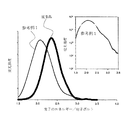
上記の酸化亜鉛基組成物に対して、5キロ電子ボルトに加速された電子線を照射し、この励起によって生じた光を市販の一般的な分光器によって分光し、市販の一般的な光検出器であるCCD検出器によって検出し、その発光スペクトルを記録した。その結果、第5図に示すようなスペクトルが得られた。太線で示す従来品が2.3電子ボルト(波長約540ナノメーター)に最強値をもつ発光を与えているのに対して、細線で示した本発明による酸化亜鉛基組成物は、アクセプター準位の形成をもたらすアルカリ金属元素とドナー準位の形成をもたらすIII族元素とを含んでおり、約2.0電子ボルト(波長約600ナノメーター)に最強値を持つ発光を示している。
【0079】
また、第5図の挿図は、本発明による蛍光体の発光スペクトルを、縦軸を対数目盛にして書き直したものである。ここに見られるように、極めて、幅の広い発光スペクトルが得られている。この2つのスペクトルは、同一の分光器、光検出器を用いて同様の測定条件で計測した結果であり、少なくとも、その相互比較が可能な実験条件で得られた結果である。
【0080】
従来品である青緑色を発する酸化亜鉛蛍光体とのスペクトルの比較から、ドナーとアクセプターを同時添加した酸化亜鉛基組成物がよりブロードな可視発光をあたえ、白色に近いスペクトルとなっている。この発光スペクトル、すなわち、室温での発光スペクトルの強度の最強値が波長550〜650ナノメーターの範囲において観測され、また、短波長側の裾が波長400ナノメーター以下にまで及び、かつ、長波長側の裾が800ナノメーター以上の長波長に及ぶ連続したスペクトルであり、用いた測定装置の誤差を加味しても、CIE1964表色系でx=0.40から0.47の範囲であり、かつ、y=0.44から0.47の範囲に相当する黄色みを帯びた色であった。すなわち、目的の蛍光体が製造された。
【実施例1】
【0081】
上記の参考例1で得られた酸化亜鉛蛍光体に対して、先に示した特許第2920207号公報に記載されているようなプラズマ発生装置によるプラズマ、すなわち、水素ガスとArガスの混合ガスにラジオ波を投入することで得られる誘導結合プラズマを照射して、酸化亜鉛蛍光体に水素を導入した蛍光体を製造した。この際の処理に供した酸化亜鉛蛍光体は、直径約8ミリ、厚さ約2ミリのペレット状のものとし、プラズマの照射時間は5分とした。この処理によって、このプラズマ処理によって水素を導入した後に得られた蛍光体の発光スペクトルを先の参考例1と同様の電子線励起による方法で評価した結果を第6図に示す。太線で示したパターンが、水素導入処理前の蛍光体であり、細い線が水素導入処理後のスペクトルである。この第6図から明らかなように、水素プラズマを使用した処理によって、水素を酸化亜鉛蛍光体に導入することによって、発光効率が改善した蛍光体が製造された。
参考例2
【0082】
上記の参考例1で得られた酸化亜鉛蛍光体に対して、酸素雰囲気中、1100℃において6時間の焼鈍処理を施した。第7図に焼鈍処理前の蛍光体(太線)と、焼鈍処理された製造物(細線)の5キロ電子ボルトに加速された電子線の照射下での発光スペクトルを示す。
【0083】
何れも、同一の装置を用い、同一の測定条件で得られたスペクトルであり、その相互比較は可能である。強度が高い方が酸素ガス中で焼鈍処理を施した蛍光体の発光スペクトルである。すなわち、酸素中での焼鈍処理によって、より発光効率の高い蛍光体が製造された。しかし、焼鈍処理を施した蛍光体に対して、さらに6時間の酸素中での焼鈍処理を加えたが、顕著な発光効率の向上は認められなかった。すなわち、焼鈍は、何らかの理由によって発光効率に低下が認められた蛍光体に対してその発光効率を回復させる働きを持つものであり、元来高い発光効率を示す蛍光体に対しては、その効果は限定的であった。
【産業上の利用可能性】
【0084】
本発明の酸化亜鉛蛍光体は、紫外線とそれよりも短波長の電磁波、又は電子線によって励起される発光装置として用いられ、交通信号やディスプレーパネルのような人の視覚に刺激を与える利用法と、写真の焼き付け用の光源や写真読み取り装置の光源のような光応答性の物体に対して、光刺激を与える露光装置としての利用法、又は蛍光塗料としての利用法などが可能である。【Technical field】
[0001]
The present invention provides a fluorescent paint that uses zinc oxide that is relatively inexpensive and can be obtained stably in terms of resources, or provides a broad visible light emission spectrum that is used in a light-emitting device. And a method for producing the same and a light emitting device using the zinc oxide phosphor.
[Background]
[0002]
The characteristic control of zinc oxide is realized by addition of additives and heat treatment. In the Craga-Fink defect equation, for example, the provision of conductivity by defect generation is described as in the following Equation 1 and
[0003]
[Chemical 1]
[Chemical formula 2]
![]()
Up to now, it is considered that the defects introduced in this way are involved in the emission of zinc oxide, and the zinc oxide phosphor that gives blue-green emission that has already been developed and put into practical use is represented by the formula 1 or Zinc oxide containing defects synthesized by two chemical reactions, in other words, the chemical formula Zn1 + xO or ZnO1-xIt is said that the composition is given by For example, as can be seen in Patent Document 1, the production is performed by heat-treating an inorganic raw material containing zinc in an atmosphere having a low oxygen partial pressure.
[0006]
Characteristic control by adding impurities to zinc oxide is realized by adding any of group III elements such as aluminum, indium, and gallium, or alkali metal elements such as sodium and lithium. The addition of these additives is described as Formula 3 and Formula 4, where Formula 3 provides conductivity by adding a Group III element represented by X, Formula 4 represents an alkali metal represented by Z. It shows the suppression of conductivity by the addition of elements.
[0007]
[Chemical 3]
[Formula 4]
Conventionally, the effect of an additive to ZnO is generally a technique of introducing either a donor or an acceptor. In principle, even in a zinc oxide group composition that gives green light emission, Zn1 + xO or ZnO1-xIt is said that it is realized in a composition as given in the above, that is, zinc oxide into which a donor is introduced.
[0010]
On the other hand, the present invention controls the emission characteristics by simultaneously adding a group III element that causes the formation of a donor level and an alkali metal element that causes the formation of an acceptor level in zinc oxide. Different.
[0011]
[0012]
An example of the phosphor that gives yellowish light emission is yttrium aluminum garnet to which cerium is added. This phosphor is used as a scintillator material. For example, Non-Patent Document 1 shows the state of light emission. In recent years, the phosphor has been used in manufacturing a semiconductor device that emits white light by being combined with a nitride semiconductor LED.
[0013]
Zn shown above1 + xO or ZnO1-xUnlike green light emission, there is a method of causing visible light emission by an additive. It activates visible luminescence by adding a lanthanide element, and its composition is shown in Patent Document 3. The zinc oxide-based composition according to the present invention is characterized in that it emits visible light using an emission line of a lanthanide element and emits only a specific wavelength. It is not a method for producing a zinc oxide group composition having a broad emission band and a continuous emission spectrum, as represented by so-called incandescent lamps. Therefore, the object of the present invention and the effects obtained therefrom cannot be achieved by the technique disclosed in Patent Document 3.
[Prior art documents]
[0014]
[Patent Literature]
[Patent Document 1]
Japanese Patent Laid-Open No. 06-093259
[Patent Document 2]
Japanese Patent Publication No. 06-070190
[Patent Document 3]
Japanese Patent Laid-Open No. 08-236275
[0015]
[Non-patent literature]
[Non-Patent Document 1]
T.A. Tamura, T .; Setmoto, and T.M. Taguchi, Journal of Luminescence, 87-89, 1180, (2000)
DISCLOSURE OF THE INVENTION
[Problems to be solved by the invention]
[0016]
Luminescence of the zinc oxide-based composition of interest in the present invention is a problem that has already been studied physically. For example, as shown by Schermel and Twingel: Solid State Communication, Vol. 8, page 1559, 1970, yellow light emission is obtained from a zinc oxide-based composition at extremely low temperatures.
[0017]
However, until now, no effective industrial production method of such a zinc oxide group composition and chemical composition for controlling the luminous efficiency have been shown, and the production method and materials are used for industrial use. The chemical composition for remained unknown. Furthermore, industrial development in terms of yellowish light emission by realizing a broad emission spectrum has not been achieved.
[0018]
The subject of the present invention is that when electrons and holes are excited in ZnO by ultraviolet rays and electromagnetic waves having a wavelength shorter than that, or an electron beam having energy exceeding the band gap of the composition, The strongest value of the emission spectrum intensity is observed in the wavelength range of 550 to 650 nanometers, the short wavelength side has a tail of 400 nm or less, and the long wavelength has a tail of 800 nm or more. This is a realization of a zinc oxide phosphor characterized by a continuous spectrum extending over a long wavelength. That is, an energy level effective for realizing the light emission is introduced into the zinc oxide group composition.
[0019]
In addition, when the light emitting function is activated in zinc oxide, defects for electric charge compensation are formed by heat treatment or addition of an additive. There are two effects of defects and additives on the emission of zinc oxide. One is the case where the defects and additives cause light emission. The electronic transition that gives this light emission is , Called radiative transition. On the other hand, a process in which the electron-hole pair excited in zinc oxide dissipates energy as heat without emitting light is also possible, and such an electronic transition is called a non-radiative transition.
[0020]
In order to enhance the function as a phosphor, it is necessary to inactivate defects that give useful radiation transitions, and to increase the probability that excited electron-hole pairs are recombined by useful radiation transitions. That is, the problem to be solved by the present invention is to reduce the probability of non-radiative transition and increase the light emission efficiency.
[Means for Solving the Problems]
[0021]
Pure zinc oxide is a semiconductor with a band gap of about 3.3 eV, and pure zinc oxide gives an ultraviolet emission of about 380 nanometers. Further, by introducing defects, blue-green light emission having a light emission intensity peak at about 520 nanometers is given. In order to obtain light emission from zinc oxide having such characteristics, a level giving a radiative transition must be further introduced in the band gap.
[0022]
In a general oxidation or heat treatment in a reducing atmosphere, only the previous green light-emitting defect is introduced, so that some additive must be added to introduce another defect. In addition, the defect introduced in this way has an energy state suitable for giving a yellowish visible light emission that is neither blue nor green for excitation by particle beams or electromagnetic waves having energy exceeding the band gap. Need to be.
[0023]
The present inventors have conducted research to realize light emission by a donor-acceptor pair, that is, light emission by the combination of electrons of a donor and holes of an acceptor. As a result, at least one of aluminum, gallium, and indium has been studied. Zinc oxide containing two or more kinds of additives and at least one of lithium and sodium, and when excited by ultraviolet rays, electromagnetic waves having a shorter wavelength than that, or electron beams, The strongest value of the emission spectrum intensity is observed in the wavelength range of 550 to 650 nanometers, the short wavelength side has a tail of 400 nm or less, and the long wavelength has a tail of 800 nm or more. A zinc oxide phosphor characterized by a continuous spectrum extending over a long wavelength has been found.
[0024]
In particular, it is a zinc oxide phosphor having a yellow color corresponding to x = 0.40 to 0.47 in the CIE 1964 color specification system and corresponding to y = 0.44 to 0.47. The zinc oxide phosphor, which is characterized by having a tinged color, becomes a phosphor that gives yellowish white light emission at room temperature.
[0025]
Here, the spread of the coordinate values of the color system is that the light emission of the phosphor according to the present invention has an afterglow characteristic, and its excitation method or excitation is continuous or pulsed. It means that there is a width in the appearance of the light emission depending on whether there is an excitation method in which the afterglow is noticeable or not.
[0026]
In order to make the phosphor more useful, it is necessary to reduce the probability of the non-radiative transition described above. A method for reducing the probability of non-radiative transition is disclosed in, for example, Japanese Patent Application Laid-Open No. 10-245550. However, in this method, not only the non-radiative transition but also the radiative transition associated with a defect is not possible. It is intended to obtain high ultraviolet light emission efficiency by being activated.
[0027]
In contrast, in the present invention, by adjusting the concentration of hydrogen introduced into the zinc oxide phosphor, only defects and impurities that give useful visible light emission in the zinc oxide phosphor are activated, and non-radiative transition is given. By deactivating visible light emission, the function as a phosphor is improved.
[0028]
As a zinc oxide phosphor with a reduced probability of non-radiative transition, a defect that causes non-radiative transition formed in the phosphor is particularly difficult for zinc oxide phosphors characterized by visible light emission. It has a surface layer in which hydrogen whose concentration is adjusted so as not to activate and inactivate defects that cause radiative transitions, or is formed in the phosphor over the entire crystal grain. A zinc oxide phosphor characterized by containing hydrogen whose concentration is adjusted so as to inactivate a defect that causes a non-radiative transition, and not to inactivate a defect that causes a radiation transition Is available.
[0029]
Here, the method for adding hydrogen is not particularly limited as long as hydrogen can be introduced into zinc oxide. However, if hydrogen is to be introduced by treatment in a high-temperature hydrogen gas, there is a risk of sublimation of zinc oxide or a shift in additive composition due to a hydrogen gas atmosphere having a low oxygen partial pressure. Therefore, it is effective to introduce hydrogen by exposing the phosphor to hydrogen plasma or activated hydrogen called hydrogen radical, and a plasma generator can be used. Such a plasma generator is known (for example, Japanese Patent No. 2920207).
[0030]
It is a further object of the present invention to provide an apparatus for exciting a zinc oxide phosphor and extracting light therefrom. The zinc oxide phosphor provided by the present invention is to obtain light emission by electromagnetic waves or particle beams exceeding the band gap energy of zinc oxide.
[0031]
The method includes (1) exciting the light emission by irradiating the zinc oxide phosphor with an electromagnetic wave having a wavelength of 375 nm or less, and (2) irradiating the zinc oxide phosphor with an electron beam. A device that obtains visible light can be obtained by either exciting the luminescence of the body.
[0032]
Furthermore, a display panel for displaying information and images can be obtained by arranging the devices for obtaining visible light in a desired pattern.
[Brief description of the drawings]
[0033]
FIG. 1 is a schematic view of a light emitting device by ultraviolet excitation according to the present invention.
FIG. 2 is a schematic view of a light emitting device by electron beam excitation according to the present invention.
FIG. 3 is a schematic view showing a mode in which a color filter is attached to a light emitting device by ultraviolet excitation according to the present invention.
FIG. 4 is a schematic view showing a mode in which a color filter is attached to a light emitting device by electron beam excitation according to the present invention.
FIG. 5 shows the present invention.the method ofbyBefore treatment to add hydrogenA zinc oxide phosphor,referenceThe phosphor manufactured in Example 1 and a comparative example(Conventional product)It is the emission spectrum by electron beam excitation of the fluorescent substance.
FIG. 6 showsreferenceExample 1 phosphor and example1Manufactured in,reference2 is an emission spectrum of a phosphor obtained by adding hydrogen to the phosphor of Example 1 by electron beam excitation.
FIG. 7 shows the present invention.the method ofbyBefore treatment to add hydrogenA zinc oxide phosphor,referenceThe phosphor produced in Example 1;Reference example 2It is the emission spectrum by the electron beam excitation of the fluorescent substance manufactured by (1).
BEST MODE FOR CARRYING OUT THE INVENTION
[0034]
(1) Composition and light emission of zinc oxide phosphor
It is recognized that the zinc oxide phosphor that is the subject of the present invention gives yellowish light emission to a particle beam having an energy exceeding the band gap energy of the composition or excitation by electromagnetic waves by visual observation. In other words, the strongest value of the intensity of the emission spectrum at room temperature is observed in the wavelength range of 550 to 650 nanometers, and the tail on the short wavelength side extends to 400 nanometers or less, and the long wavelength side The zinc oxide phosphor is characterized by having a continuous spectrum extending over a long wavelength of 800 nanometers or more, regardless of the method of production thereof, zinc oxide as a main component, and aluminum, Contains at least one additive of at least one of gallium and indium and at least one of lithium and sodium. Zinc oxide group composition, wherein the zinc oxide.
[0035]
In addition, the zinc oxide phosphor that is an object of the present invention is the zinc oxide group composition, and in order to further increase the luminous efficiency, defects that cause non-radiative transitions formed in the phosphor are removed. It has a surface layer in which hydrogen whose concentration has been adjusted so as not to deactivate and cause defects that cause radiative transitions, or is formed in the phosphor throughout the entire particle. A zinc oxide phosphor characterized by containing hydrogen whose concentration is adjusted so as to inactivate a defect that causes a non-radiative transition, and not to inactivate a defect that causes a radiation transition It is.
[0036]
In addition, the zinc oxide phosphor that is an object of the present invention is the zinc oxide group composition, and depending on the composition, the color development when visually observed is x = 0.40 to 0.47 in the CIE1964 color system. The zinc oxide phosphor is characterized by being in a range and having a yellowish color corresponding to y = 0.44 to 0.47.
[0037]
Furthermore, the zinc oxide phosphor that is an object of the present invention is the zinc oxide group composition, and the color development when visually observed is x = 0.40 to 0.47 in the CIE1964 color system. A zinc oxide phosphor characterized by being in the range and having a yellowish color corresponding to y = 0.44 to 0.47, and in order to further increase its luminous efficiency, A surface layer in which hydrogen whose concentration has been adjusted so as not to inactivate defects that cause non-radiative transitions formed in the body and to inactivate defects that cause radiative transitions. In order to inactivate defects that cause non-radiative transitions formed in the phosphor throughout the particle and not to inactivate defects that cause radiative transitions. Characterized by containing conditioned hydrogen That is a zinc oxide phosphor.
[0038]
Here, the composition of the zinc oxide used when manufacturing the zinc oxide phosphor of the present invention is at least one of an inorganic salt or oxide containing aluminum, gallium, and indium, and an inorganic salt containing lithium, sodium, or It is zinc oxide to which at least one of the oxides and a total of two or more additives are added.
[0039]
The concentration of these additives in zinc oxide is defined by its solid solubility limit. On the other hand, the solid solubility limit of these additives in zinc oxide varies depending on the environment in which the zinc oxide phosphor is placed, that is, the heat treatment temperature and oxygen partial pressure when producing the solid solution.
[0040]
The maximum value of the amount of impurities added to control the emission wavelength is defined by the solid solution limit. The solid solution limit depends on the temperature and oxygen partial pressure at the time of synthesizing the material, but cannot be specified unconditionally. However, the maximum value of aluminum, indium and gallium is about 3000 PPM, and about 1000 ppm for sodium and lithium. Become. As for the minimum level for obtaining a certain level of luminous efficiency, 500 ppm or more is appropriate for aluminum, gallium, and indium, and 100 ppm or more is appropriate for lithium and sodium. Since these impurities are the source of light emission, the higher the concentration, the better the light emission. However, in the method of emitting light by irradiating with an electron beam, if the electrical resistance becomes too high, the light emission efficiency decreases. Therefore, it is necessary to adjust the addition amount of lithium and sodium.
[0041]
Further, when heat is applied during the process of producing a solid solution, lithium or sodium, which is characterized by being easily volatilized, may not be dissolved in the phosphor but may be vaporized and damaged. Therefore, when producing a solid solution, the initial composition for producing the solid solution is determined in consideration of the heat treatment temperature and atmosphere when producing the solid solution, and further the vaporization evaporation of the raw material in the process of producing the solid solution. There is a need.
[0042]
In the present invention, the strongest value of the intensity of the emission spectrum is observed in the wavelength range of 550 to 650 nanometers, the tail on the short wavelength side extends to a wavelength of 400 nanometers or less, and the tail on the long wavelength side is 800. In order to obtain a zinc oxide phosphor characterized by having a continuous spectrum extending over a long wavelength of nanometer or more, a total of at least one of aluminum, gallium, and indium and at least one of lithium and sodium is obtained. This shows that it is effective to obtain zinc oxide containing two or more additives, and the optimum conditions for the luminous efficiency need to be optimized during the production.
[0043]
(2) Simple production method of the composition
When excited by ultraviolet rays and electromagnetic waves having a shorter wavelength than that, or an electron beam, the strongest value of the intensity of the emission spectrum at room temperature is observed in the wavelength range of 550 to 650 nanometers. In addition, the zinc oxide phosphor is characterized in that the short wavelength side has a continuous spectrum extending to a wavelength of 400 nanometers or less and the long wavelength side has a long wavelength of 800 nanometers or more. One of the manufacturing methods is a combination of at least one alkali metal element mainly composed of zinc oxide, which causes formation of an acceptor level, and at least one group III element, which causes formation of a donor level. It is to produce a zinc oxide group composition characterized by containing two or more subcomponents.
[0044]
One of the manufacturing methods is, in particular, at least one of an inorganic salt or oxide containing aluminum, gallium, or indium and at least one of an inorganic salt or oxide containing lithium or sodium, for a total of two or more. In this method, the zinc oxide to which the additive is added is heat-treated at a high temperature sufficient for the additive to be dissolved in the zinc oxide crystal.
[0045]
As an alkali metal raw material, an oxide (Li2O, Na2O), carbonate (Li2COThree, Na2COThree), Nitrate (Li2NOThree, Na2NOThree), Hydroxides (LiOH, NaOH), metals (Li, Na), etc. can be used, but in general, their hygroscopicity and reactivity make accurate weighing and safe handling difficult. It is convenient to use a compound having a carbonate form.
[0046]
In addition, as a group III element material, oxide (Al2OThree, Ga2OThree, In2OThreeEtc.) is convenient. Although it is possible to use fluorides in principle, fluorine generated by decomposition may remain as a subcomponent of the zinc oxide group composition after heat treatment. It is desirable to use an oxide as a raw material. In addition, depending on the reactivity of the raw material to be added, added Li2COThreeAnd Al2OThreeSuch a raw material must react sufficiently with zinc oxide as a main component, and heat treatment must be performed at a temperature sufficient to form a donor level and an acceptor level contributing to light emission in the zinc oxide group composition.
[0047]
For example, commercially available powdered reagent Li2COThreeAnd the commonly available powder reagent Al2OThreeIs added to zinc oxide, which is a commercially available powder reagent, and heat treatment is not particularly limited, and the heat treatment is performed in a range of 800 ° C. to 1100 ° C. for 3 hours to 12 hours. Is desirable. However, since the heat treatment conditions depend on the additive raw material and the powder particle size of the zinc oxide raw material which is the main component, the heat treatment temperature and the heat treatment time are adjusted according to the form of the raw material used in the production. There is a need.
[0048]
The heat treatment atmosphere is not particularly limited, but it is desirable to perform the heat treatment in an oxygen atmosphere except for the purpose of obtaining a light emitting material exhibiting an electrically low resistance. In particular, an alkali metal element has a high vapor pressure, and is easily evaporated and lost when the temperature is raised. Therefore, the alkali metal element has a temperature at which the additive and the main component zinc oxide react with each other, and the alkali metal does not evaporate. There is no problem even if a method of heating to a temperature that does not become noticeable, starting the reaction and calcining, and then heat-treating at a higher temperature is acceptable.
[0049]
This calcination differs depending on the raw material to be used. When a raw material having a high decomposition temperature must be used, this calcination must be performed at a higher temperature. For example, the calcination temperature when gallium oxide and lithium carbonate are used is preferably 800 ° C. to 1000 ° C.
[0050]
In addition, when the heat treatment is performed at an excessively high temperature or an excessively low oxygen partial pressure, the evaporation of zinc oxide as a main component or alkali metal elements or group III elements as subcomponents becomes remarkable, Since the luminescent material comprising the zinc oxide-based composition according to the invention may not have the desired characteristics, it is desirable that the temperature and atmosphere of the heat treatment be performed under conditions that do not cause a significant composition change due to evaporation. However, the method shown here is an example of a simple method, and whether or not to implement this method is not necessarily a necessary matter in the present invention.
[0051]
One of simple manufacturing methods other than the above is a solution containing at least one alkali metal element that causes the formation of an acceptor level in zinc oxide with respect to zinc oxide powder (LiCl, NaCl aqueous solution or a solution thereof). A solution diluted with alcohols) and a solution containing at least one group III element that causes formation of a donor level in zinc oxide (Al (NOThree)ThreeAn aqueous solution or a solution obtained by diluting it with an alcohol), followed by drying and mixing, or kneading and drying, and then applying a heat treatment to react the mixture.
[0052]
The process of kneading and drying or drying and mixing is not particularly concerned before and after, but even if the order is appropriately changed depending on the amount of the solution to be added, the influence on the entire production process can be ignored. Drying and mixing may be performed simultaneously. The drying conditions are such that, in the heat treatment performed after drying, if the evaporation of volatile components (such as moisture) does not interfere with the reaction and recovery of the product, in particular, the temperature for the drying step, The atmosphere is not limited. As a result, any technique that can achieve a state in which the main component and the added alkali metal and group III element are well mixed does not give a significant difference to the characteristics of the product.
[0053]
In addition, with respect to the heat treatment, the donor level and the acceptor level that contribute to light emission are formed in the zinc oxide group composition by sufficiently reacting with zinc oxide, which is mainly composed of subcomponents such as lithium and aluminum. It must be heat-treated at a sufficient temperature. For example, when heat treatment is performed by adding an aqueous lithium chloride solution and aluminum nitrate to zinc oxide, which is a commercially available powder reagent, in a heat treatment apparatus that does not specifically limit the heating mechanism, the temperature is in the range of 800 ° C. to 1100 ° C. for 3 hours. It is desirable to perform a heat treatment for 12 hours.
[0054]
However, since the heat treatment conditions depend on the additive raw material and the powder particle size of the zinc oxide raw material which is the main component, it is necessary to adjust the heat treatment temperature and the heat treatment time depending on the form of the raw material used in production. is there. The heat treatment atmosphere is not particularly limited, but it is desirable to perform the heat treatment in an oxygen atmosphere except for the purpose of obtaining a light emitting material exhibiting an electrically low resistance. In particular, an alkali metal element has a high vapor pressure, and is easily evaporated and lost when the temperature is raised. Therefore, the alkali metal element has a temperature at which the additive and the main component zinc oxide react with each other, and the alkali metal does not evaporate. There is no problem even if a method of once heating to a temperature that does not become noticeable and initiating the reaction and then heat-treating at a higher temperature is acceptable.
[0055]
In addition, when the heat treatment is performed at an excessively high temperature or an excessively low oxygen partial pressure, the evaporation of zinc oxide as a main component or alkali metal elements or group III elements as subcomponents becomes remarkable, Since the luminescent material comprising the zinc oxide-based composition according to the invention may not have the desired characteristics, it is desirable that the temperature and atmosphere of the heat treatment be performed under conditions that do not cause a significant composition change due to evaporation. However, the method shown here is an example of a simple method, and whether or not to implement this method is not necessarily a necessary matter in the present invention.
[0056]
Further, in the heat treatment performed in the course of the manufacturing method shown above, in which a mixture is reacted to form a donor and an acceptor in a zinc oxide group composition, the mixture is reacted in oxygen gas to obtain a product. Therefore, the improvement of the luminous efficiency may be recognized. The oxygen partial pressure needs to be adjusted depending on the characteristics required for the product (here, luminous efficiency and electrical resistivity). Since the electrical resistance of the product increases as the oxygen partial pressure increases, it is necessary to adjust the oxygen partial pressure so that a product closest to the desired characteristics can be obtained. However, the production in the oxygen atmosphere is not necessarily a necessary matter in the present invention.
[0057]
In the production, the luminous efficiency may be improved by subjecting the composition to a heat treatment in an atmosphere mainly composed of oxygen. Therefore, in the final process at the time of manufacturing the composition, annealing the composition in a gas containing oxygen as a main component may be effective in improving luminous efficiency.
[0058]
The annealing treatment referred to here is performed after the manufacturing process shown above, and zinc oxide as a main component is added to any one of group III elements among aluminum, gallium, and indium as a subcomponent. In order to adjust the characteristics of the zinc oxide group composition in which the donor level and the acceptor level are already formed by at least two additives of any one of lithium and sodium, It is not something that must be done.
[0059]
The annealing treatment referred to here is for changing the amount and state of defects, and is therefore preferably performed at the most effective temperature between 400 ° C and 1100 ° C. That is, since the concentration and state of defect species such as oxygen defects in zinc oxide are affected by both temperature and oxygen partial pressure, desired characteristics (here, luminous efficiency and electrical conductivity) or It is necessary to adjust the temperature and atmosphere so that close characteristics can be obtained. In general, oxygen vacancies tend to decrease when the temperature is low and the oxygen partial pressure is high. However, when the temperature is low, the diffusion coefficient of ions in the solid decreases, and a long-time treatment is required.
[0060]
Further, the sufficient annealing time varies depending on the size of the zinc oxide-based composition to be manufactured. Therefore, for example, assuming a pellet-like product having a diameter of 10 mm and a thickness of 2 mm, the annealing treatment conditions that can be effective in a finite time are satisfied with oxygen at 1 atmosphere at a temperature of 800 ° C. to 1100 ° C. A suitable condition is that after heating for 1 to 10 hours in the heat treatment apparatus, the temperature is lowered to room temperature for 3 to 6 hours in the same atmosphere. It is necessary to examine the processing conditions according to the shape and density of the product and find the optimum conditions. However, annealing in this oxygen atmosphere is not an essential requirement in the present invention.
[0061]
In addition, it becomes easy to handle by forming the powder into a green compact at a pressure that does not easily break the green compact. The weighting in this case is not so essential for the properties of the material. By molding into a green compact, an effect of suppressing evaporation of sodium and lithium in the processed product is expected. However, on the other hand, when it is fired as a green compact, it takes time and effort to grind it when used in a powder state. Therefore, pressure molding of powder is not an essential requirement in the present invention.
[0062]
By adding a treatment for adding hydrogen to the composition obtained by any one of the zinc oxide phosphor manufacturing methods described above, an improvement in the luminous efficiency may be observed. Therefore, in the final process at the time of manufacturing the composition, it may be effective to improve the luminous efficiency to add hydrogen to the entire phosphor or the surface of the phosphor. The hydrogenation referred to here is performed after the manufacturing process shown above, and zinc oxide as a main component is added to any one of group III elements, aluminum, gallium, and indium, as a subcomponent. In order to adjust the characteristics of the zinc oxide group composition in which the donor level and the acceptor level have already been formed by at least two additives of any one of lithium and sodium,
However, it is not something that must be done.
[0063]
The most typical method of hydrogenation is a method using plasma. Although it is possible to add hydrogen to the phosphor by heat treatment in a state of flowing hydrogen gas, if zinc oxide is heated in a reducing atmosphere with hydrogen, evaporation of zinc oxide or defect concentration in zinc oxide Depending on the degree of reduction, the luminous efficiency of the zinc oxide phosphor to be produced according to the present invention may be impaired. By using a plasma capable of providing atomic hydrogen, hydrogen can be added without causing significant evaporation or reduction of the phosphor due to its high chemical reactivity.
[0064]
When hydrogenating the zinc oxide phosphor, it is important not to make the amount of hydrogen excessive. When excessive hydrogen is introduced, the yellowish white broad light emission originally intended by the present invention may be impaired. That is, the hydrogenation treatment of the present invention does not change the state of the additive that brings about the target light emission, and the target light emission.EffectIt is to change the state of the defect that lowers the rate and suppress non-radiative transitions. Further, depending on the manufacturing conditions of the phosphor, the concentration of defects that cause non-radiative transition may be low. In that case, even if hydrogen is added, the improvement in luminous efficiency cannot be expected. That is, the hydrogenation according to the present invention is not necessarily required for improving the function of the phosphor, but should be performed as necessary.
[0065]
There are several methods for adding hydrogen to a zinc oxide phosphor by irradiation with a plasma containing hydrogen.WhenThere are high-pressure plasma generated at low pressure and low-pressure plasma generated under high vacuum. In any case, it is necessary to carry out after optimizing the processing conditions by the plasma generation method. The optimization of the processing conditions is, for example, changing the input power for generating plasma or the distance between the plasma flame and the phosphor to be processed to change several kinds of hydrogenated phosphors. Manufactured and evaluated by evaluating its emission spectrum. It is possible to optimize the conditions by obtaining the hydrogenation treatment conditions such that an emission spectrum most suitable for the purpose can be obtained under predetermined excitation conditions.
[0066]
(3) Light emitting device
A light-emitting device using the zinc oxide phosphor according to the present invention, wherein the light emission device is excited by irradiating the zinc oxide phosphor with an electromagnetic wave having a wavelength of 375 nm or less. Thus, an apparatus using the light emission of the phosphor is configured.
[0067]
That is, a light emitting device that emits light is formed by applying excitation with sufficient intensity to the phosphor using a general ultraviolet light source as an excitation source. Here, the ultraviolet light source includes a discharge tube or a solid ultraviolet light emitting element. That is, it is also possible to apply a phosphor inside the discharge tube and use ultraviolet rays emitted by the discharge as a light source. FIG. 1 shows a schematic diagram of the light emitting device. It is an example of the light-emitting device which installed the fluorescent tube (14) which emits a general ultraviolet-ray behind the glass substrate (13) which apply | coated the zinc oxide fluorescent substance (12) of this invention. The light emitting device can be used as a method of applying a stimulus to human vision and as an exposure device that applies a light stimulus to a light-responsive object.
[0068]
Here, it should be noted that if the excitation intensity is strong beyond the range suitable for the phosphor, the phosphor may emit band edge emission, that is, ultraviolet emission. It is necessary to adjust according to the luminous efficiency of the body. Among the light emitting devices shown in FIG. 1, a light emitting device in which a fluorescent tube, which is an ultraviolet light source, is replaced with a pulsed ultraviolet light source composed of a combination of a Q switch Nd: YVO pulse laser and a nonlinear optical crystal emitting a fourth harmonic. Is that. Here, the pulse light source using the Q switch Nd: YVO has a power density of 100 times or more compared to the ultraviolet light source using the fluorescent tube. In the light-emitting device using this high-power pulse laser as the excitation source, the energy consumed for the increase in the ultraviolet light emission intensity among the energy invested in the excitation increases, and the visible light emission intensity enough to meet the increase in the input energy. Since an increase cannot be obtained, high-efficiency visible light emission may not necessarily be obtained.
[0069]
Further, a light-emitting device using the zinc oxide phosphor according to the present invention is configured to excite the light emission of the phosphor by irradiating the zinc oxide phosphor with an electron beam. .
[0070]
That is, by accelerating the electrons generated from various electron beam sources including thermionic electrons and field emitters and irradiating the phosphor, it has sufficient energy to form sufficient electron-hole pairs in the phosphor. Light emission is obtained by irradiating the electrons.
[0071]
Here, there is no particular limitation on the mechanism for generating the electron beam, and a thermal electron or an electron beam emitted by field emission is generally available. That is, (1) a mechanism for generating an electron beam sufficient to obtain an appropriate irradiation intensity is included, and (2) sufficient kinetic energy is sufficient to generate an electron-hole pair in the zinc oxide phosphor. And (3) an electrode for discharging the charge so that the charge poured into the phosphor by electron beam irradiation does not accumulate in the phosphor and enter a charge-up state. (Grounding electrode) is provided, and (4) the present invention is any apparatus provided with a light extraction port made of a light-transmitting material that enables emitted fluorescence to illuminate a target location. Is a light emitting device included. In particular, when an electron beam generating mechanism that draws an electron beam by an electric field is provided, a common mechanism can be used for the electron beam generating mechanism and the mechanism for accelerating the electron beam.
[0072]
Here, it should be noted that if the excitation intensity is strong beyond the range suitable for the phosphor, the phosphor may emit band edge emission, that is, ultraviolet emission. It is necessary to adjust according to the luminous efficiency of the body. FIG. 2 shows a schematic diagram of the light emitting device. As shown in FIG. 2, the thermoelectron beam source (1), electron beam acceleration electrode (3), ground (5), collector mirror (6), light extraction window (7), and phosphor (8) are vacuumed. Installed in the package (9) as the light emitting device body, connected to the thermoelectron generating power source (2) and electron beam acceleration power source (4) prepared outside the package, respectively, the thermionic beam source (1), And the light-emitting device connected with an electron beam acceleration electrode (3) is comprised. The phosphor (8) is irradiated with an electron beam from the thermal electron beam source (1) to extract light through the light extraction window. The device shown here is an example of a light-emitting device configuration, and the condenser mirror (6) is not an essential component. By making the vacuum package (9) transparent, the light extraction window (7) may not be necessary, and is essentially a device that can irradiate the phosphor with an electron beam. The light emitting device can be used as a method of applying a stimulus to human vision and as an exposure device that applies a light stimulus to a light-responsive object.
[0073]
Furthermore, it is a light-emitting device using the zinc oxide phosphor of the present invention, wherein the phosphor is made to emit light by using ultraviolet rays or an electron beam for excitation of the phosphor. A light emitting device characterized in that broad light emission obtained by exciting a zinc oxide phosphor with rays or ultraviolet rays is passed through a color filter, and only light in a limited wavelength region is extracted from the device and used. Is possible.
[0074]
FIG. 3 shows a schematic view of the light emitting device. FIG. 1 shows an example of a light-emitting device that emits red-orange light by attaching a general color filter (31) that absorbs light having a wavelength shorter than 600 nm to the light-emitting device shown in FIG. The light emitting device can be used as a method of applying a stimulus to human vision and as an exposure device that applies a light stimulus to a light-responsive object. Similarly, FIG. 4 shows a schematic diagram of the light emitting device. FIG. 2 shows an example of a light-emitting device that emits red-orange light by attaching a general color filter (21) that absorbs light having a wavelength shorter than 600 nm to the light-emitting device shown in FIG.
(Example)
referenceExample 1
[0075]
Compared to the commercially available 99.999% pure zinc oxide powder reagent, the atomic ratio to zinc is such that the concentration of gallium is 1 / 1,000 and lithium is 1 / 10,000. The powder and lithium carbonate powder are mixed, and the mixed powder is put in an alumina porcelain, set in an electric furnace, which is a general heating device, and placed at 800 ° C. in an oxygen atmosphere supplied from a commercially available oxygen gas cylinder. By reacting for a period of time, in particular, the lithium carbonate salt of the lithium source was decomposed, and carbon dioxide gas was vaporized and desorbed. Note that the amount of lithium added was reduced so as not to increase the resistance.
[0076]
The reaction product obtained here was loaded with 1 ton, molded into a pellet shape with a diameter of 10 mm and a thickness of 3 mm, and this molded product was re-inserted into alumina porcelain. In addition, it was fired in an oxygen atmosphere at 1100 ° C., thereby obtaining a zinc oxide group composition in which gallium and lithium were dissolved.
[0077]
When the zinc oxide group composition obtained by the above method was irradiated with light having a wavelength of about 355 nanometers or about 245 nanometers, the light emitted by the composition was visually observed. As a result, it was confirmed that the intended phosphor was produced. When a conventional zinc oxide phosphor having a composition containing excess zinc was observed in the same manner, blue-green light emission was visually confirmed.
[0078]
The above zinc oxide-based composition is irradiated with an electron beam accelerated to 5 kV, and the light generated by this excitation is dispersed by a commercially available general spectrometer, and a commercially available general light detection is performed. The emission spectrum was recorded by a CCD detector. As a result, a spectrum as shown in FIG. 5 was obtained. While the conventional product indicated by the thick line gives the light emission having the strongest value at 2.3 electron volts (wavelength of about 540 nanometers), the zinc oxide-based composition according to the present invention indicated by the thin line shows the acceptor level. In addition, an alkali metal element that causes the formation of a hydrogen atom and a group III element that causes the formation of a donor level, and emits light having the strongest value at about 2.0 electron volts (wavelength: about 600 nanometers).
[0079]
Further, the inset of FIG. 5 is a rewrite of the emission spectrum of the phosphor according to the present invention with the vertical axis representing a logarithmic scale. As can be seen here, an extremely broad emission spectrum is obtained. These two spectra are the results obtained under the same measurement conditions using the same spectroscope and photodetector, and at least the results obtained under experimental conditions that allow mutual comparison.
[0080]
From the comparison of the spectrum with the conventional zinc oxide phosphor emitting blue-green, the zinc oxide group composition to which the donor and the acceptor are added at the same time gives a broader visible light emission and has a spectrum close to white. This emission spectrum, that is, the strongest value of the intensity of the emission spectrum at room temperature is observed in the wavelength range of 550 to 650 nanometers, and the short wavelength side skirt extends to a wavelength of 400 nanometers or less. It is a continuous spectrum with a long tail of 800 nm or more on the side, and even if the error of the measuring device used is taken into account, it is in the range of x = 0.40 to 0.47 in the CIE1964 color system, And it was a yellowish color corresponding to the range of y = 0.44 to 0.47. That is, the target phosphor was manufactured.
【Example1]
[0081]
abovereferenceFor the zinc oxide phosphor obtained in Example 1, a radio wave is applied to the plasma generated by the plasma generator as described in the aforementioned Japanese Patent No. 2920207, that is, a mixed gas of hydrogen gas and Ar gas. Irradiated with inductively coupled plasma obtained by charging, a phosphor was produced by introducing hydrogen into the zinc oxide phosphor. The zinc oxide phosphor used in this treatment was in the form of a pellet having a diameter of about 8 mm and a thickness of about 2 mm, and the plasma irradiation time was 5 minutes. By this treatment, the emission spectrum of the phosphor obtained after introducing hydrogen by this plasma treatment is changed to the previous one.referenceFIG. 6 shows the results of evaluation by the same electron beam excitation method as in Example 1. The pattern indicated by the thick line is the phosphor before the hydrogen introduction treatment, and the thin line is the spectrum after the hydrogen introduction treatment. As is apparent from FIG. 6, a phosphor with improved luminous efficiency was produced by introducing hydrogen into the zinc oxide phosphor by a treatment using hydrogen plasma.
Reference example 2
[0082]
abovereferenceThe zinc oxide phosphor obtained in Example 1 was subjected to an annealing treatment at 1100 ° C. for 6 hours in an oxygen atmosphere. FIG. 7 shows the emission spectra of the phosphor before annealing (thick line) and the annealed product (thin line) under irradiation with an electron beam accelerated to 5 kV.
[0083]
All are spectra obtained using the same apparatus and under the same measurement conditions, and their mutual comparison is possible. The higher the intensity is the emission spectrum of the phosphor that has been annealed in oxygen gas. That is, a phosphor with higher luminous efficiency was produced by annealing in oxygen. However, the phosphor subjected to the annealing treatment was further subjected to an annealing treatment in oxygen for 6 hours, but no significant improvement in luminous efficiency was observed. In other words, annealing has a function of recovering the luminous efficiency of phosphors whose luminous efficiency has been reduced for some reason, and the effect is effective for phosphors that originally show high luminous efficiency. Was limited.
[Industrial applicability]
[0084]
The zinc oxide phosphor of the present invention is used as a light-emitting device excited by ultraviolet rays and electromagnetic waves having a shorter wavelength than that, or an electron beam, and is used for stimulating human vision such as traffic signals and display panels. The light-responsive object such as a light source for printing a photograph or a light source of a photo-reading apparatus can be used as an exposure device that gives a light stimulus, or can be used as a fluorescent paint.
Claims (8)
該発光の色が、CIE1964表色系でx=0.40から0.47の範囲であり、かつ、y=0.44から0.47の範囲になる黄色みを帯びた色であり、かつ紫外線とそれよりも短波長の電磁波、又は電子線によって励起した際に、その室温での発光スペクトルの強度の最強値が波長550〜650ナノメーターの範囲において観測され、また、短波長側の裾が波長400ナノメーター以下にまで及び、かつ、長波長側の裾が800ナノメーター以上の長波長に及ぶ連続したスペクトルとなることを特徴とする酸化亜鉛蛍光体。Including aluminum addition amount 500ppm~ solubility limit, gallium, and at least one of indium, lithium addition amount 100ppm~ solubility limit, at least one of sodium, a total of two or more kinds of additives In order to inactivate defects that cause non-radiative transitions formed in the phosphor and to inactivate defects that cause radiative transitions. Inactivate defects that cause a non-radiative transition formed in the phosphor throughout the phosphor particles, having a surface layer in which hydrogen whose concentration is adjusted so as not to reach And hydrogen adjusted in concentration so as not to inactivate defects that cause radiative transitions,
The emission color is a yellowish color in the range of x = 0.40 to 0.47 and y = 0.44 to 0.47 in the CIE1964 color system; and When excited by ultraviolet rays, electromagnetic waves having a shorter wavelength than that, or an electron beam, the strongest value of the emission spectrum intensity at room temperature is observed in the wavelength range of 550 to 650 nanometers, The zinc oxide phosphor is characterized by having a continuous spectrum extending up to a wavelength of 400 nanometers or less and having a tail on the long wavelength side extending to a long wavelength of 800 nanometers or more.
のうちの少なくとも一種、の計2種以上の添加物を含む酸化亜鉛に対して水素プラズマを使用した水素を添加する処理によって、蛍光体粒子の表面層、又は粒子全体に亘って含有水素濃度を調整することを特徴とする請求の範囲第1項記載の酸化亜鉛蛍光体の製造法。Aluminum, gallium, and at least one of indium, lithium, by at least one, adding hydrogen using a hydrogen plasma against the zinc oxide containing a total of two or more additives treatment of sodium, fluorescent 2. The method for producing a zinc oxide phosphor according to claim 1, wherein the hydrogen concentration is adjusted over the surface layer of the body particles or over the entire particles.
Applications Claiming Priority (3)
| Application Number | Priority Date | Filing Date | Title |
|---|---|---|---|
| JP2003124743 | 2003-04-30 | ||
| JP2003124743 | 2003-04-30 | ||
| PCT/JP2004/006402 WO2004096949A1 (en) | 2003-04-30 | 2004-04-30 | Zinc oxide phosphor, process for producing the same and light emitting device |
Publications (2)
| Publication Number | Publication Date |
|---|---|
| JPWO2004096949A1 JPWO2004096949A1 (en) | 2006-07-13 |
| JP4635184B2 true JP4635184B2 (en) | 2011-02-16 |
Family
ID=33410198
Family Applications (1)
| Application Number | Title | Priority Date | Filing Date |
|---|---|---|---|
| JP2005505959A Expired - Fee Related JP4635184B2 (en) | 2003-04-30 | 2004-04-30 | Zinc oxide phosphor, method for producing the same and light emitting device |
Country Status (5)
| Country | Link |
|---|---|
| US (1) | US7535162B2 (en) |
| EP (1) | EP1630218B1 (en) |
| JP (1) | JP4635184B2 (en) |
| KR (1) | KR100666663B1 (en) |
| WO (1) | WO2004096949A1 (en) |
Families Citing this family (9)
| Publication number | Priority date | Publication date | Assignee | Title |
|---|---|---|---|---|
| WO2007018216A1 (en) * | 2005-08-09 | 2007-02-15 | Stanley Electric Co., Ltd. | ZnO CRYSTAL, METHOD FOR GROWING THE CRYSTAL, AND METHOD FOR MANUFACTURE OF LIGHT-EMITTING ELEMENT |
| CN100509998C (en) * | 2005-11-26 | 2009-07-08 | 中国科学院合肥物质科学研究院 | Zinc oxide nanosheet film material with ultraviolet luminescent properties and preparation method thereof |
| JP2009286856A (en) * | 2008-05-27 | 2009-12-10 | Fukuda Crystal Laboratory | Scintillator material, method for manufacturing the same, and ionizing radiation detector |
| WO2011035294A2 (en) * | 2009-09-21 | 2011-03-24 | University Of Georgia Research Foundation, Inc. | Near infrared doped phosphors having an alkaline gallate matrix |
| WO2011035292A2 (en) | 2009-09-21 | 2011-03-24 | University Of Georgia Research Foundation, Inc. | Near infrared doped phosphors having a zinc, germanium, gallate matrix |
| US8778228B2 (en) | 2011-09-27 | 2014-07-15 | Panasonic Corporation | Method of producing ultraviolet light emitting phosphor material |
| CN102660264B (en) * | 2012-04-17 | 2014-06-04 | 绍兴文理学院 | ZnO-based fluorescent powder material for near-ultraviolet excited white-light LED and preparation method thereof |
| RU2520892C2 (en) * | 2012-07-06 | 2014-06-27 | Министерство образования и науки Федеральное государственное бюджетное образовательное учреждение высшего профессионального образования "Норильский индустриальный институт" (ФГБОУ ВПО "НИИ") | Method of processing zinc oxide phosphors |
| US12464888B2 (en) * | 2020-09-23 | 2025-11-04 | Beijing Boe Technology Development Co., Ltd. | Quantum dot light emitting diode, manufacturing method thereof and display apparatus |
Citations (1)
| Publication number | Priority date | Publication date | Assignee | Title |
|---|---|---|---|---|
| JP2003231878A (en) * | 2002-02-08 | 2003-08-19 | National Institute For Materials Science | Zinc oxide-based composition emitting yellowish light and method for producing the same |
Family Cites Families (16)
| Publication number | Priority date | Publication date | Assignee | Title |
|---|---|---|---|---|
| US3583928A (en) * | 1967-10-03 | 1971-06-08 | Westinghouse Electric Corp | High-speed phosphors and methods to prepare same |
| JPH066704B2 (en) * | 1987-12-24 | 1994-01-26 | 双葉電子工業株式会社 | Electron beam excited phosphor and method for producing the same |
| JP2535218B2 (en) | 1989-03-01 | 1996-09-18 | 日亜化学工業株式会社 | Self-activated zinc oxide phosphor |
| US5094693A (en) * | 1990-02-20 | 1992-03-10 | International Lead Zinc Research Organization, Inc. | Doped zinc oxide-based pigment |
| JP3116586B2 (en) | 1992-08-18 | 2000-12-11 | 松下電器産業株式会社 | Flyback transformer |
| JPH08236275A (en) | 1995-02-28 | 1996-09-13 | Olympus Optical Co Ltd | Luminescent material, its manufacture and luminescent element using its luminescent material |
| JPH103990A (en) * | 1996-06-13 | 1998-01-06 | Idemitsu Kosan Co Ltd | Organic EL light emitting device |
| JP3785721B2 (en) * | 1997-02-28 | 2006-06-14 | 住友電気工業株式会社 | ZnO ultraviolet light emitter and method for producing the same |
| JP2920207B2 (en) | 1997-06-04 | 1999-07-19 | 科学技術庁無機材質研究所長 | Energy control method of thermal plasma |
| JP4126332B2 (en) * | 1999-08-13 | 2008-07-30 | 学校法人高知工科大学 | Low resistance p-type single crystal zinc oxide and method for producing the same |
| JP4059620B2 (en) * | 2000-09-20 | 2008-03-12 | 株式会社リコー | Coordinate detection method, coordinate input / detection device, and storage medium |
| US20030012984A1 (en) * | 2001-07-11 | 2003-01-16 | Tetsuzo Ueda | Buffer layer and growth method for subsequent epitaxial growth of III-V nitride semiconductors |
| JP2003051609A (en) * | 2001-08-03 | 2003-02-21 | Tokyo Gas Co Ltd | Diamond high-intensity ultraviolet light emitting element |
| US7362357B2 (en) * | 2001-08-07 | 2008-04-22 | Signature Research, Inc. | Calibration of digital color imagery |
| JP2003142262A (en) * | 2001-11-06 | 2003-05-16 | Seiko Epson Corp | Electro-optical device, film-like member, laminated film, low refractive index film, multilayer laminated film, electronic equipment |
| JP2004182813A (en) * | 2002-12-02 | 2004-07-02 | Futaba Corp | Warm-colored luminescent fluorophor and fluorescent display tube using the same |
-
2004
- 2004-04-30 KR KR1020057015493A patent/KR100666663B1/en not_active Expired - Fee Related
- 2004-04-30 JP JP2005505959A patent/JP4635184B2/en not_active Expired - Fee Related
- 2004-04-30 WO PCT/JP2004/006402 patent/WO2004096949A1/en not_active Ceased
- 2004-04-30 US US10/554,724 patent/US7535162B2/en not_active Expired - Fee Related
- 2004-04-30 EP EP04730742.6A patent/EP1630218B1/en not_active Expired - Lifetime
Patent Citations (1)
| Publication number | Priority date | Publication date | Assignee | Title |
|---|---|---|---|---|
| JP2003231878A (en) * | 2002-02-08 | 2003-08-19 | National Institute For Materials Science | Zinc oxide-based composition emitting yellowish light and method for producing the same |
Also Published As
| Publication number | Publication date |
|---|---|
| EP1630218A4 (en) | 2009-04-29 |
| US20070158615A1 (en) | 2007-07-12 |
| EP1630218B1 (en) | 2014-08-20 |
| JPWO2004096949A1 (en) | 2006-07-13 |
| EP1630218A1 (en) | 2006-03-01 |
| KR20050100698A (en) | 2005-10-19 |
| US7535162B2 (en) | 2009-05-19 |
| WO2004096949A1 (en) | 2004-11-11 |
| KR100666663B1 (en) | 2007-01-09 |
Similar Documents
| Publication | Publication Date | Title |
|---|---|---|
| Palilla et al. | Fluorescent properties of alkaline earth aluminates of the type MAl2 O 4 activated by divalent europium | |
| Kumari et al. | Simultaneous influence of Zn 2+/Mg 2+ on the luminescent behaviour of La 2 O 3: Tm 3+–Yb 3+ phosphors | |
| WO2005087896A1 (en) | Phosphor, process for producing the same, lighting fixture and image display unit | |
| TWI390011B (en) | Green phosphor | |
| Cherepy et al. | Red-emitting manganese-doped aluminum nitride phosphor | |
| Swart et al. | PL and CL degradation and characteristics of SrAl2O4: Eu2+, Dy3+ phosphors | |
| Yang et al. | Ultraviolet long afterglow emission in Bi3+ doped CdSiO3 phosphors | |
| Li et al. | Sintering condition and optical properties of Zn3V2O8 phosphor | |
| JP2017501274A (en) | Zinc sulfide phosphor having photoluminescence and electroluminescence properties, method for producing the same, security document, security feature and method for detecting the same | |
| Zvonarev et al. | Luminescent properties of alumina ceramics doped with manganese and magnesium | |
| Som et al. | Dopant distribution and influence of sonication temperature on the pure red light emission of mixed oxide phosphor for solid state lighting | |
| JP4836229B2 (en) | Phosphor and light emitting device | |
| JP4635184B2 (en) | Zinc oxide phosphor, method for producing the same and light emitting device | |
| Katayama | Red to near-infrared persistent luminescence in transition metal ion activated phosphors | |
| Verma et al. | Luminescence Properties of CaAl₂O₄: Eu³⁺, Gd³⁺ Phosphors Synthesized by Combustion Synthesis Method | |
| Chaika et al. | Spectroscopic properties of Cr, Yb: YAG nanocrystals under intense NIR radiation | |
| US6419852B1 (en) | Use as phosphor dot in a plasma or x-ray system of a lanthanum phosphate comprising thulium | |
| Jaiswal et al. | Luminescence enhancement of high temperature hexagonal phase of Ba0. 99MgAl10O17: Eu0. 01 nanophosphor synthesized at moderately low temperature | |
| Stefanski et al. | Studies of graphene influence on the laser induced white emission spectra of Sr 2 CeO 4/graphene flake composites | |
| JP3849011B2 (en) | Luminescent material emitting yellowish light and its manufacturing method | |
| Ji et al. | Enhanced long lasting persistent luminescent SrAl2O4: Eu, Dy ceramics prepared by electron beam bombardment | |
| Rajeswari et al. | Synthesis, structural and luminescent properties of novel Eu3+: Y2CaZnO5 nanophosphor for white light-emitting diodes | |
| Sokolnicki | Enhanced luminescence of Tb3+ due to efficient energy transfer from Ce3+ in a nanocrystalline Lu2Si2O7 host lattice | |
| EP2785815A1 (en) | Phosphor blends for fluorescent lamps | |
| JP5034033B2 (en) | Plate-like phosphor and display using it |
Legal Events
| Date | Code | Title | Description |
|---|---|---|---|
| RD02 | Notification of acceptance of power of attorney |
Free format text: JAPANESE INTERMEDIATE CODE: A7422 Effective date: 20050817 |
|
| A521 | Request for written amendment filed |
Free format text: JAPANESE INTERMEDIATE CODE: A821 Effective date: 20050817 |
|
| A521 | Request for written amendment filed |
Free format text: JAPANESE INTERMEDIATE CODE: A523 Effective date: 20061121 |
|
| A621 | Written request for application examination |
Free format text: JAPANESE INTERMEDIATE CODE: A621 Effective date: 20070420 |
|
| A621 | Written request for application examination |
Free format text: JAPANESE INTERMEDIATE CODE: A621 Effective date: 20070420 |
|
| A131 | Notification of reasons for refusal |
Free format text: JAPANESE INTERMEDIATE CODE: A131 Effective date: 20100518 |
|
| A521 | Request for written amendment filed |
Free format text: JAPANESE INTERMEDIATE CODE: A523 Effective date: 20100716 |
|
| TRDD | Decision of grant or rejection written | ||
| A01 | Written decision to grant a patent or to grant a registration (utility model) |
Free format text: JAPANESE INTERMEDIATE CODE: A01 Effective date: 20101026 |
|
| A01 | Written decision to grant a patent or to grant a registration (utility model) |
Free format text: JAPANESE INTERMEDIATE CODE: A01 |
|
| A61 | First payment of annual fees (during grant procedure) |
Free format text: JAPANESE INTERMEDIATE CODE: A61 Effective date: 20101027 |
|
| FPAY | Renewal fee payment (event date is renewal date of database) |
Free format text: PAYMENT UNTIL: 20131203 Year of fee payment: 3 |
|
| R150 | Certificate of patent or registration of utility model |
Free format text: JAPANESE INTERMEDIATE CODE: R150 |
|
| FPAY | Renewal fee payment (event date is renewal date of database) |
Free format text: PAYMENT UNTIL: 20131203 Year of fee payment: 3 |
|
| R250 | Receipt of annual fees |
Free format text: JAPANESE INTERMEDIATE CODE: R250 |
|
| S533 | Written request for registration of change of name |
Free format text: JAPANESE INTERMEDIATE CODE: R313533 |
|
| R350 | Written notification of registration of transfer |
Free format text: JAPANESE INTERMEDIATE CODE: R350 |
|
| R250 | Receipt of annual fees |
Free format text: JAPANESE INTERMEDIATE CODE: R250 |
|
| LAPS | Cancellation because of no payment of annual fees |