JP4635170B2 - Image forming body - Google Patents
Image forming body Download PDFInfo
- Publication number
- JP4635170B2 JP4635170B2 JP2005180131A JP2005180131A JP4635170B2 JP 4635170 B2 JP4635170 B2 JP 4635170B2 JP 2005180131 A JP2005180131 A JP 2005180131A JP 2005180131 A JP2005180131 A JP 2005180131A JP 4635170 B2 JP4635170 B2 JP 4635170B2
- Authority
- JP
- Japan
- Prior art keywords
- image
- light
- ultraviolet
- wavelength
- area ratio
- Prior art date
- Legal status (The legal status is an assumption and is not a legal conclusion. Google has not performed a legal analysis and makes no representation as to the accuracy of the status listed.)
- Expired - Fee Related
Links
Images


Landscapes
- Credit Cards Or The Like (AREA)
Description
本発明は、紫外線領域の異なった波長域において発光強度が著しく異なる励起特性を有する発光体を使用し、特定の波長域の第1の紫外線を照射した際に発現する発光画像と、第1の紫外線と異なる波長域の第2の紫外線を照射した際に発現する発光画像との間で画像をスイッチさせる画像形成体に関する。 The present invention uses an illuminant having excitation characteristics with significantly different emission intensities in different wavelength regions of the ultraviolet region, and a luminescent image that appears when the first ultraviolet ray in a specific wavelength region is irradiated, The present invention relates to an image forming body that switches an image between a luminescent image that appears when irradiated with a second ultraviolet ray having a wavelength range different from the ultraviolet ray.
蛍光体、燐光体、蓄光体等に代表されるいわゆる、紫外線励起発光体は、紫外線を照射することで励起して発光する特性を有している。この発光という現象は容易に目視確認可能であり、かつ、コピー機による複写物や家庭用プリンターによる出力物では再現が困難である。このことから、銀行券や諸証券、郵券等のセキュリティが必要な印刷物に対して、発光体で画線を構成した発光画線や発光体を繊維や紙料に定着させた発光体形成物を付与する技術は、真性品と偽造品を区別するための真偽判別要素の一つとして、従来から広く用いられてきた。 A so-called ultraviolet-excited illuminant typified by a phosphor, a phosphor, a phosphorescent substance, and the like has a characteristic of being excited to emit light when irradiated with ultraviolet rays. This phenomenon of light emission can be easily visually confirmed, and is difficult to reproduce with a copy by a copier or an output by a home printer. Therefore, for printed matter that requires security, such as banknotes, securities, and postal tickets, a luminous body formed of a luminous body and a luminous body formed by fixing the luminous body to a fiber or paper material are used. The technology to be applied has been widely used as one of authenticity determination elements for distinguishing between genuine products and counterfeit products.
また、発光体の赤、緑、青といった色(色相)と、照射する紫外線の波長や照射光量に応じた光のスペクトル及び強さ(発光強度)はそれぞれの発光体に固有の特性であることから、たとえ偽造品に発光画線や発光形成体が用いられた場合でも、真性品と異なる発光体である場合には、色相と発光強度によって真性発光体と偽造発光体を差別化することが可能である。一例として、暗闇の中でブラックライトや紫外線LEDを用いて日本銀行券に紫外線を照射した場合、印章部分や一部の画線が緑色又は黄色に強く発光して浮かび上がることを確認することができる。鑑別者は、発光している部位、色相及び発光強度を判定基準として簡易的な官能検査で鑑別対象物の真偽を判別することが可能である。 In addition, the color (hue) of light emitters such as red, green, and blue, and the spectrum and intensity (light emission intensity) of light according to the wavelength of ultraviolet light and the amount of light to be emitted are unique to each light emitter. Therefore, even if a light emission image line or a light emission forming body is used for a counterfeit product, if the light emitter is different from the genuine product, the intrinsic light emitter and the counterfeit light emitter may be differentiated by hue and light emission intensity. Is possible. As an example, when irradiating banknotes with UV light in the dark using a black light or UV LED, it is possible to confirm that the seal part or part of the line is strongly emitted in green or yellow and emerges. it can. The discriminator can determine the authenticity of the discrimination target by a simple sensory test using the light emitting part, the hue, and the light emission intensity as the determination criteria.
このように発光体印刷や発光体形成物をセキュリティが要求される貴重製品に施すことは、特殊印刷を業とした印刷関係者にとって単純な方法で貴重印刷物の真偽判別性を容易に維持することが可能であることから、偽造防止の観点から考えると極めて効果的な手段の一つであった。 Applying light-emitting material printing or light-emitting material formation to a valuable product that requires security in this way easily maintains the authenticity of the valuable printed material in a simple manner for those involved in printing. From the viewpoint of counterfeiting, it was one of the most effective means.
しかし、前述の発光体印刷や発光体形成物の真偽判別技術としての優位性は、実際には限られた専門業者や特殊印刷に従事する者しか発光体を入手できないという材料自体の入手難易度に大きく依存している面があった。昨今、発光体は雑貨量販店において比較的安価で販売されており、特殊印刷に従事することのない一般人であっても様々な種類の発光体を容易に入手することができる状況になっている。 However, the superiority of the above-mentioned light emitter printing and light emitter formation as a true / false discrimination technique is that the material itself is difficult to obtain because only a limited number of specialists or special printing personnel can obtain the light emitter. There were aspects that depended heavily on the degree. In recent years, luminous bodies are sold at a relatively low price in general merchandise stores, and even ordinary people who are not engaged in special printing can easily obtain various types of luminous bodies. .
本来、発光体印刷物における真偽判別要素としては、発光部位、発光の色相、発光強度の主たる3要素が存在しており、特に色相と発光強度を一致させるためには、真性品と化学的な構造が同一の発光体を使用する必要がある。実際には真性品と同一の発光体を一般人が入手することは今日においても極めて困難である。 Originally, as the authenticity determination element in the printed matter of the light emitting body, there are three main elements of the light emitting part, the hue of light emission, and the light emission intensity. It is necessary to use light emitters having the same structure. Actually, it is very difficult even today to obtain the same illuminant as the genuine product.
しかし、偽造券が持ち込まれる可能性があるチケット取扱店に代表される貴重印刷物の換金においては、持ち込まれた貴重印刷物に対してブラックライトを使用して真偽判別を行う場合はあるものの、その観察環境は太陽光が差し込んでいたり、蛍光灯の光で照らし出されたり等、外乱光が存在する状況下での判別を余儀なくされてしまう。このような観察環境においては、外乱光の影響を特に大きく受ける発光強度に関しては、判別要素として機能させることは実際には極めて難しい。 However, in the exchange of valuable prints represented by ticket dealers where there is a possibility that counterfeit tickets may be brought in, there are cases in which authenticity is determined using black light for the valuable prints brought in. The observation environment is inevitably discriminated in the presence of ambient light, such as when sunlight is inserted or illuminated by fluorescent light. In such an observation environment, it is actually very difficult to function as a discriminating element with respect to the emission intensity that is particularly greatly affected by disturbance light.
また、像や文字、記号として表現可能な発光部位や、赤・橙・黄・緑・青・藍・紫との言語表現が可能な色相と異なり、官能検査においては「強い」、「弱い」以外での言語表現が困難であり、「強い」、「弱い」の表現を用いる場合でも、その基準を明確にすることが困難である。厳密に言えば官能検査による場合、真性品を基準サンプルとして判定対象物の隣に置き、同じ環境下で比較しない限り、発光強度を用いた正当な官能評価は困難であると言える。 Also, unlike light emitting parts that can be represented as images, characters, symbols, and hues that can be expressed in red, orange, yellow, green, blue, indigo, and purple, sensory tests are "strong" and "weak" It is difficult to express other languages, and even when “strong” and “weak” expressions are used, it is difficult to clarify the criteria. Strictly speaking, in the case of sensory inspection, it can be said that legitimate sensory evaluation using luminescence intensity is difficult unless an authentic product is placed next to a determination target as a reference sample and compared in the same environment.
当然のことながら、光電変換センサを用いることで発光強度を数値として表現することは可能であるが、装置の普及に当たっては製造者や確認者に金銭的負担を強いるものとなるとともに、装置による数値確認を行う場合、確認手順が煩雑になることは明らかであることに加え、対面販売・交換を行う場合において正当な顧客の前で重々しい機械を用いて頻繁に確認を行うことは今日の日本の風土においては双方の心情的に望ましくない場合が多々存在すると思われ、現時点では望ましい確認手段ではない。 As a matter of course, it is possible to express the light emission intensity as a numerical value by using a photoelectric conversion sensor. However, when the device is spread, it imposes a financial burden on the manufacturer and the confirmer, and the numerical value by the device. It is clear that the confirmation procedure becomes complicated when confirming, and in addition, when performing face-to-face sales and exchanges, frequent confirmation using a heavy machine in front of a legitimate customer is today's Japan It seems that there are many cases where both sides are undesirably desirable in this climate, and it is not a desirable confirmation means at this time.
以上のように、発光体印刷物や発光体形成体の真偽判別要素であるべき発光強度は実際には有効に機能させることは困難であり、真性品と異なった発光体を用いた偽造品であってもその発光部位と色相が一致していれば、真性品と判断される可能性が少なからず存在すると思われる。現在の発光体の販売状況を踏まえると、一般人が入手可能な発光体は多種多様の色相に及ぶことから、発光体印刷における偽造抵抗力は低下していると考えられる。 As described above, it is difficult to make the light emission intensity that should be the authenticity determination element of the printed matter of the luminous body and the luminous body formation actually function effectively, and it is a counterfeit product using a luminous body different from the genuine product. Even if it exists, if the light emitting part and the hue match, there is a high possibility that it is judged to be an authentic product. Considering the current sales situation of illuminants, the illuminant available to the general public covers a wide variety of hues, so it is considered that the counterfeit resistance in illuminant printing is reduced.
このことを鑑みて現在、発光体印刷物の真偽判別性を向上させた技術が望まれている。以下に参考として発光体印刷物の真偽判別性を向上させた技術の例を挙げる。 In view of this, there is a demand for a technique that improves the authenticity discrimination of the light-emitting printed matter. The following is an example of a technique that improves the authenticity discrimination of the luminescent material printed matter as a reference.
例えば、発光体印刷物の真偽判別性を向上させる一つの手段として、発光体の発光自体を特殊化する技術がある。これは一つのインキに2種類の発光体を用い、紫外線照射波長に応じて色相を2種類に変化させる二色性発光インキが使用される場合がある(例えば、特許文献1参照)。これは長波の紫外線域(波長400nm〜300nm、中心波長365nm)を照射した場合には長波の紫外線励起タイプの発光体1がある一定の色相1で発光し、短波の紫外線域(波長300nm〜200nm、中心波長254nm)を照射した場合には長波の紫外線励起タイプの発光体1と短波励起タイプの発光体2が同時に発光することで長波の紫外線照射時の発光色とは異なった色相2を発するものであり、例えば、長波の紫外線で赤発光していた画線が短波の紫外線の照射では緑色の発光に変化するものである。公知の例としてはフランスの500フランに同一部位で2色の発光を示す印刷部位がある。この機能を兼ね備えた発光体は、現在のところ一般的な雑貨量販店では販売されていないことから、2色発光を示す発光体を用いた発光体印刷物は、従来の単色発光の発光体印刷物と比較して偽造抵抗力は向上すると考えられる。
For example, as one means for improving authenticity discrimination of a light-emitting printed matter, there is a technique for specializing light emission of the light-emitting body. In some cases, a dichroic light emitting ink is used in which two types of light emitters are used for one ink and the hue is changed into two types according to the ultraviolet irradiation wavelength (see, for example, Patent Document 1). When a long wave ultraviolet region (
また一方、画線構成によって発光体印刷物の真偽判別性を高めた技術も存在する。これは着色顔料と発光体を混合した有色発光インキを使用して特殊な画線構成を用いることで、1種類のインキのみで可視光観察時と紫外線照射時とで発光像を変化させる技術である。これは多くの場合、着色発光画線に可視光観察下では目視で差別化できない程度に画線部を微細に分断させた領域を設けて、発光時の光の広がりによる画線の拡大作用を用いたものである。この技術によって、単純な画線構成では成しえない画像変化を得ることが可能となり、一般的な発光体印刷物と比較して2色の発光を示す発光体を使用した例と同様に真偽判別性は向上すると思われる(例えば、特許文献2参照)。 On the other hand, there is also a technique that improves the authenticity discrimination of the luminescent printed material by the image line configuration. This is a technology that uses a colored light-emitting ink that is a mixture of a colored pigment and a light-emitting body and uses a special image line configuration to change the light-emitting image between visible light observation and ultraviolet irradiation with only one type of ink. is there. In many cases, the colored light-emitting image line is provided with a region where the image line portion is finely divided to the extent that it cannot be visually differentiated under visible light observation, and the effect of expanding the image line due to the spread of light during light emission is provided. It is what was used. This technology makes it possible to obtain an image change that cannot be achieved with a simple image line configuration, and is true or false as in the case of using a light emitter that emits two colors of light compared to a general light emitter print. It seems that the discriminability is improved (see, for example, Patent Document 2).
さらに、紫外線領域のある一定の波長域とそれ以外の波長域で発光部位を変化させる技術が存在する。これは、印刷のインキに用いられる樹脂や印刷基材となるプラスティックが短波の紫外線を特に強く吸収したり、反射したり作用を有するいわゆる紫外線吸収特性又は反射特性を有する紫外線遮断剤を用いたもので、発光体と紫外線遮断剤を重ね合わせて構成することで長波の紫外線照射時に発光していた像が短波の紫外線を照射した場合には発光しない効果を得るものが一般的である(例えば、特許文献3)。 Furthermore, there is a technique for changing a light emitting site in a certain wavelength region having an ultraviolet region and other wavelength regions. This is because the resin used for printing ink and the plastic used as the printing substrate absorb ultraviolet rays in the short wave particularly strongly, and reflect or reflect so-called ultraviolet ray-absorbing or reflecting properties. Therefore, it is common to obtain an effect of not emitting light when an image emitted during irradiation with long-wave ultraviolet rays is irradiated with short-wave ultraviolet rays by superposing a light emitter and an ultraviolet blocking agent (for example, Patent Document 3).
しかし、2色の発光を示す発光体に使用する発光体は2種類の発光体でニつの色相変化を見せるために、主として短波の紫外線(254nmを中心とする。)で発光ピークが略最大になる発光体と、主として長波の紫外線(365nmを中心とする。)で発光ピークが略最大になる色相の異なる発光体の二つの発光体を組み合わせで設計されているのが一般的である。この2色の発光を示す発光体に用いられるこれら長波の紫外線励起タイプの発光体及び短波の紫外線励起タイプの発光体は、発光印刷を行う印刷分野において既に公知であることに加え、青、赤、緑といった、おおまかな色相ごとに数種類の発光体が発光体製造メーカからそれぞれ販売されていることから、ある程度の発光体の知見を有する者であれば一般的な二色性発光体の色相の再現は可能であると思われる。 However, since the light emitters used for the light emitters exhibiting two colors of light show two hue changes with two kinds of light emitters, the light emission peak is substantially maximized mainly by short-wave ultraviolet rays (centered at 254 nm). In general, the two light emitters are designed in combination with a light emitter having a different hue that has a light emission peak substantially at a maximum with a long wave ultraviolet ray (centered at 365 nm). These long-wave ultraviolet-excited light emitters and short-wave ultraviolet-excited light emitters used for these two-color light emitters are already known in the printing field for performing light-emission printing, as well as blue, red There are several types of illuminants, such as green, for each of the approximate hues sold by the illuminant manufacturers, so if you have some knowledge of illuminants, Reproduction seems possible.
また、特殊な画線構成を用いて可視光観察時の像と紫外線照射時の像を変化させる技術については、偽造者が着色画線と発光画線を別々のインキによって2色印刷を行う場合において、真性品のような特殊な画線構成を用いなくとも一般人を欺ける程度に真性品に近づけることが可能である。また、昨今のDTPに代表されるデジタル製版技術の裾野の広がりによって、高精細な網点・画線構成に関する印刷会社の技術的優位性は失われつつあり、真性品と同一の画線構成をほぼ完全に近い状態で再現することは将来的には可能になると考えられる。 In addition, with regard to the technology that changes the image during visible light observation and the image during ultraviolet irradiation using a special image line configuration, when a counterfeiter performs two-color printing of a color image line and a light-emitting image line using different inks. However, it is possible to approach the genuine product to such an extent that the general public can be deceived without using a special image line configuration such as the genuine product. Also, due to the recent expansion of digital plate making technology represented by DTP, the technical advantage of printing companies regarding high-definition halftone dot and image line composition is being lost. In the future, it will be possible to reproduce in a nearly perfect state.
さらに、紫外線の波長に応じて発光部位を変化させる技術に関しては、紫外線吸収特性又は反射特性を有する紫外線遮断剤を用いる単純な構成であることから、付与した発光体を発光させない技術がベースであることに問題がある。紫外線遮断剤は、ある一定の紫外線を吸収又は反射する物質であるため、例えば、短波の吸収特性又は反射特性を有する紫外線遮断剤を使用した場合には長波の紫外線で発光していた部分を短波の紫外線で発光させないことは可能であっても、紫外線の長波で発光していなかった部位を紫外線の短波で発光させることは不可能であり、長波の紫外線吸収特性又は反射特性を有する紫外線遮断剤を使用した場合には、その逆が不可能である。このように、当該技術の発光変化は発光部位の部分的又は全面的な削除であることから、波長の違いに応じてユーザの望む像を自在に結ばせることは実際には不可能である。加えて、紫外線吸収・反射特性を有する物質は発光体と比較しても極めて容易に入手可能であることから、その他の技術と複合して使用するのであればともかく、その構成が単純な場合に限ってはその偽造は難しくないと考えられる。 Furthermore, regarding the technology for changing the light emitting site in accordance with the wavelength of ultraviolet rays, the technology is based on a simple configuration using an ultraviolet blocking agent having ultraviolet absorption characteristics or reflection characteristics, so that the applied light emitter does not emit light. There is a problem. An ultraviolet blocker is a substance that absorbs or reflects certain ultraviolet rays. For example, when an ultraviolet blocker having absorption or reflection characteristics of short waves is used, the portion emitting light with long wave ultraviolet rays is reduced to short waves. Although it is possible not to emit light with ultraviolet light, it is impossible to emit light with short ultraviolet light at a site that did not emit light with long ultraviolet light, and an ultraviolet blocking agent having long-wave ultraviolet absorption or reflection characteristics. The reverse is not possible when using. As described above, since the light emission change of the technique is partial or complete deletion of the light emitting part, it is actually impossible to freely form an image desired by the user according to the difference in wavelength. In addition, UV absorbing / reflecting materials are very readily available compared to illuminants, so if they are used in combination with other technologies, the structure is simple. For the time being, counterfeiting is not difficult.
以上のように、現時点の発光体印刷において用いられている進歩的な技術であっても、昨今の発光体の入手の容易性やデジタル製版技術の裾野の拡大といった周辺動向を鑑みた場合には、近い将来には十分ではない可能性があるという問題があった。 As described above, even if it is the advanced technology used in the current illuminant printing, when considering the peripheral trends such as the recent availability of illuminants and the expansion of the base of digital platemaking technology, There was a problem that may not be enough in the near future.
本発明は、上記課題の解決を目的とするものであり、具体的には、紫外線領域の異なった波長域で発光強度が著しく異なる励起特性を有する発光体を使用し、ある一定の波長域の第1の紫外線を照射した際に発現する発光画像と、第1の紫外線と異なる波長域の第2の紫外線を照射した際に発現する発光画像とを、それぞれ所定の網点面積率や画線ピッチ等に差異を設けた異なる構成で印刷し、その上に紫外線吸収剤を刷り合わせて、第1の波長の紫外線と第2の波長の紫外線とで発光画像をスイッチさせる画像形成体を提供することを目的とする。 The present invention aims to solve the above-mentioned problems. Specifically, the present invention uses a light emitter having excitation characteristics with significantly different emission intensities in different wavelength regions in the ultraviolet region, and has a certain wavelength region. A predetermined halftone dot area ratio and an image line are respectively obtained for a luminescent image that appears when the first ultraviolet ray is irradiated and a luminescent image that appears when the second ultraviolet ray in a wavelength region different from the first ultraviolet ray is irradiated. Provided is an image forming body that prints with a different configuration having a difference in pitch or the like, and prints an ultraviolet absorber thereon to switch a light emission image between ultraviolet rays having a first wavelength and ultraviolet rays having a second wavelength. For the purpose.
本発明の画像形成体は、基材上に、第1の印刷画像と第2の印刷画像を形成し、第1の印刷画像を紫外線遮断剤によって隠蔽する隠蔽層を形成した画像形成体であって、第1の印刷画像は第2の印刷画像よりも画像面積率が高く、第1の印刷画像と第2の印刷画像は、紫外線領域で発光強度が異なる特性を有する同一の発光インキで印刷し、発光インキは、第1の波長の紫外線照射により可視光領域で発光する発光強度が、第2の波長の紫外線照射により可視光領域で発光する発光強度の少なくとも20倍を有し、紫外線遮断剤は、紫外線照射により第1の波長の紫外線を遮断する遮断率が、第2の波長の紫外線を遮断する遮断率よりも高い特性を有することを特徴とする。 The image forming body of the present invention is an image forming body in which a first printed image and a second printed image are formed on a substrate, and a concealing layer for concealing the first printed image with an ultraviolet blocking agent is formed. Thus, the first printed image has a higher image area ratio than the second printed image, and the first printed image and the second printed image are printed with the same luminescent ink having a characteristic that the luminescence intensity is different in the ultraviolet region. The luminescent ink has a light emission intensity that emits light in the visible light region when irradiated with ultraviolet light of the first wavelength, and has a light emission intensity of at least 20 times that emitted in the visible light region when irradiated with ultraviolet light of the second wavelength. The agent is characterized in that the blocking rate for blocking ultraviolet rays of the first wavelength by ultraviolet irradiation is higher than the blocking rate for blocking ultraviolet rays of the second wavelength.
本発明の画像形成体は、基材上に、第1の印刷画像と第2の印刷画像を形成し、第1の印刷画像を紫外線遮断剤によって隠蔽する隠蔽層を形成した画像形成体であって、第1の印刷画像は第2の印刷画像よりも画像面積率が高く、第1の印刷画像と第2の印刷画像は、紫外線領域で発光強度が異なる特性を有する同一の発光インキで印刷し、発光インキは、第2の波長の紫外線照射により可視光領域で発光する発光強度が、第1の波長の紫外線照射により可視光領域で発光する発光強度の少なくとも20倍を有し、紫外線遮断剤は、紫外線照射により第1の波長の紫外線を遮断する遮断率が、第2の波長の紫外線を遮断する遮断率よりも高い特性を有することを特徴とする。 The image forming body of the present invention is an image forming body in which a first printed image and a second printed image are formed on a substrate, and a concealing layer for concealing the first printed image with an ultraviolet blocking agent is formed. Thus, the first printed image has a higher image area ratio than the second printed image, and the first printed image and the second printed image are printed with the same luminescent ink having a characteristic that the luminescence intensity is different in the ultraviolet region. The luminescent ink has a light emission intensity that emits light in the visible light region when irradiated with ultraviolet light of the second wavelength, and has a light emission intensity of at least 20 times that emitted in the visible light region when irradiated with ultraviolet light of the first wavelength. The agent is characterized in that the blocking rate for blocking ultraviolet rays of the first wavelength by ultraviolet irradiation is higher than the blocking rate for blocking ultraviolet rays of the second wavelength.
本発明の画像形成体は、第1の印刷画像領域及び第2の印刷画像領域を構成してなる画像面積率が、網点で構成されてなる網点面積率及び/又は複数の画線で構成されてなる画線面積率であることを特徴とする。 In the image forming body of the present invention, the image area ratio formed of the first print image area and the second print image area is a dot area ratio formed of halftone dots and / or a plurality of image lines. The image area ratio is configured.
可視光で観察した時の画像と、照射する紫外線の波長ごとに発現する複数の発光画像とで、それぞれすべて、全く形状に相関のない画像を出現させることが可能である。また、紫外線吸収特性又は反射特性を有する紫外線遮断剤に着色顔料を混合して有色化することで、可視光観察下でも全く別の画像を生じさせることが可能であり、真偽判別性が向上する。 It is possible to cause an image that has no correlation to the shape at all, between an image observed with visible light and a plurality of light-emitting images that appear for each wavelength of ultraviolet light to be irradiated. In addition, by mixing colored pigments with UV-blocking agents that have UV absorption or reflection characteristics, it is possible to produce completely different images even under visible light observation, improving authenticity discrimination To do.
また、ユーザの希望によって第2の紫外線波長を照射した場合に画像領域1の画像と画像領域2の画像を同時に発光させる場合には、本発明の構成の一部である紫外線吸収特性又は反射特性を有する紫外線遮断剤を使用せず、発光体の1色刷りのみで効果を得ることができ、極めて容易に実施することができる。また、可視光観察下で全くの無像とする場合には、紫外線吸収特性又は反射特性を有する紫外線遮断剤に着色顔料を混合しなければ容易に効果を得ることができる。
Further, when the image of the image region 1 and the image of the
さらに、本来なら真偽判別要素の一つとなるべき発光体の発光強度が、人が認識することが困難な理由として、比較対象とすべき基準があいまいであることが挙げられ、強弱の表現に関しては何に対して強いのか、何に対して弱いのかの基準となるサンプルが必要となった。本発明を利用した画像形成体の場合、波長ごとに異なった画像を見せるとともに、一方の画像の発光強度が他方の発光強度の基準となり各画像間の発光強度の相対評価が可能となる。第1画像と比較して第2画像の発光が強い、第2画像と比較して第1画像の発光が強い、又は第1画像と第2画像の発光強度が同じである、といった評価が可能となる。また、使用する発光体や画線構成によっては、発光強度を任意に調節することも可能である。 Furthermore, the reason why it is difficult for humans to recognize the light intensity of a light emitter that should be one of the true / false discrimination elements is that the standard to be compared is ambiguous. We needed a sample that would be a reference for what is strong against and what is weak against. In the case of the image forming body using the present invention, different images are displayed for each wavelength, and the emission intensity of one image becomes a reference for the emission intensity of the other, and the relative evaluation of the emission intensity between the images is possible. Evaluation is possible such that the second image is stronger than the first image, the first image is stronger than the second image, or the first and second images have the same light intensity. It becomes. Further, the emission intensity can be arbitrarily adjusted depending on the illuminant used and the image line configuration.
さらに、本発明で得られた画像形成体の偽造を試みる場合、発光体について精通している必要があり、少なくとも発光体の励起特性についての知見がなければ発光体の選定自体が困難である。また、発光体をインキ化する際には、発光画線とワニスやメジューム、ビヒクルといった印刷媒体との接着剤となる樹脂の吸収特性についての知識がなければ、同一の発光体を用いたとしても、樹脂成分に紫外線を吸収されて発光画線の発光強度が変化してしまうため、鮮やかな画像の変化を発現することは困難である。また、真性品の画線を観察して同一の画線構成で印刷したとしても、使用した発光体や樹脂が異なれば、その効果は全く発揮されず偽造は困難である。 Furthermore, when attempting to counterfeit the image forming body obtained in the present invention, it is necessary to be familiar with the illuminant, and it is difficult to select the illuminant without knowledge of at least the excitation characteristics of the illuminant. In addition, when the light emitter is made into an ink, even if the same light emitter is used unless there is knowledge of the absorption characteristics of the resin that serves as an adhesive between the light emission line and the printing medium such as varnish, medium, and vehicle. Since the resin component absorbs ultraviolet rays and the emission intensity of the emission line changes, it is difficult to express a vivid image change. Further, even if an image of an authentic product is observed and printed with the same image configuration, if the illuminant or resin used is different, the effect is not exhibited at all, and counterfeiting is difficult.
また、上で述べた発光体の選定及び選定する発光体の励起特性の知識に加え、その発光体の画像面積率の条件設定、刷り合わせに技術を必要とするため、更に偽造困難性が向上する。 In addition to the selection of the light emitter described above and the knowledge of the excitation characteristics of the light emitter to be selected, the technology for setting the conditions for the image area ratio and printing of the light emitter is further improved, further improving the forgery difficulty. To do.
さらに、異なった波長の紫外線を照射した場合に、それぞれの画像の発光強度の比較が可能であるため、その強度の再現を行う必要があることは従来の技術と比較して本発明の偽造抵抗力を向上させている要素の一つである。また、本発明に使用する発光体については、2色の発光を示す発光体などの色相変化を有するといった、材料自体の真偽判別性が高い発光体と複合して使用することで、そのセキュリティレベルをより一層引き上げることが可能である。 Furthermore, since it is possible to compare the emission intensity of each image when irradiated with ultraviolet rays of different wavelengths, it is necessary to reproduce the intensity. It is one of the factors that improve the power. In addition, the illuminant used in the present invention is used in combination with an illuminant that has a hue change such as an illuminant that emits light of two colors and has high authenticity discrimination of the material itself. It is possible to raise the level further.
次に、本発明の実施形態について説明する。 Next, an embodiment of the present invention will be described.
紫外線の照射波長によって発光体の発光強度が変化する励起特性はそれぞれの発光体に固有のものであり、化学的構造の異なる発光体においては、この励起特性はそれぞれ異なっている。通常、発光体印刷の分野において発光体の細やかな励起特性を細分化して扱うことは多くない。 The excitation characteristics in which the light emission intensity of the illuminant changes depending on the irradiation wavelength of the ultraviolet light is unique to each illuminant, and the illuminators having different chemical structures have different excitation characteristics. Usually, in the field of illuminant printing, the fine excitation characteristics of illuminants are not often subdivided.
しかし、同じ長波励起タイプに大別される発光体であっても、短波の紫外線照射において長波の紫外線の照射と比較して発光強度が強くなるものもあれば、発光強度が弱くなるものや、ほとんど変化しないもの等、照射する紫外線波長に対する変化はそれぞれの発光体固有のものとなる。本発明においては、様々な発光体の中でも、ある一定の波長では発光強度が強いが、異なった波長において著しく発光強度が低下する励起特性を有した発光体を選択的に用いる。 However, even if the light emitters are roughly classified into the same long wave excitation type, there are those in which the emission intensity becomes stronger compared to the irradiation of the long wave ultraviolet rays in the short wave ultraviolet irradiation, the emission intensity becomes weak, Changes with respect to the ultraviolet wavelength to be irradiated, such as those that hardly change, are specific to each light emitter. In the present invention, among various illuminants, an illuminant having excitation characteristics in which the emission intensity is strong at a certain wavelength but the emission intensity is significantly reduced at different wavelengths is selectively used.
このような特定の発光体に限っては、限定された画像面積率や画線の形状、印刷膜厚等の印刷条件によって紫外線のある波長である第1の紫外線波長では発光が目視で確認できないが、第1の紫外線波長と異なった第2の紫外線波長では発光が目視で確認できる現象が発生する。 For such specific light emitters, light emission cannot be visually confirmed at the first ultraviolet wavelength, which is the wavelength with ultraviolet rays, depending on the printing conditions such as the limited image area ratio, the shape of the image line, and the printing film thickness. However, a phenomenon in which light emission can be visually confirmed occurs at a second ultraviolet wavelength different from the first ultraviolet wavelength.
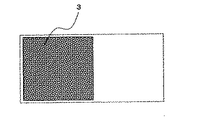
この現象を利用し、例えば、第1の紫外線波長では目視で発光を確認できないが、第1の紫外線波長と異なる第2の紫外線波長では目視で発光を確認できる発光体の画像面積率を20%とし、画像面積率100%で構成した画像領域1と画像面積率20%で構成した画像領域2に対して、第1の紫外線波長を照射した場合には、画像領域1のみが目視で発光していることを確認できる領域となる。また、第2の紫外線波長を照射した場合には、画像領域1に加えて画像領域2が同時に発光することとなり、第1の紫外線波長と第2の紫外線波長における像変化が可能となる。
Utilizing this phenomenon, for example, the image area ratio of a light emitter that cannot visually confirm light emission at the first ultraviolet wavelength but can visually confirm light emission at a second ultraviolet wavelength different from the first ultraviolet wavelength is 20%. When the first ultraviolet wavelength is irradiated to the image area 1 configured with an image area ratio of 100% and the
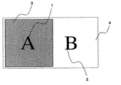
ただし、第2の紫外線波長を照射時に画像領域1は必ず発光し続けてしまうことから、第2の紫外線波長を照射した場合に発光する像を画像領域1と全く異なった像とすることは不可能であり、かつ、第2の紫外線波長照射時には画像面積率の違いから、画像領域1が画像領域2に比較して極めて強く発光することとなり、スイッチ画像としては強弱の混ざり合ったアンバランスなものとなる。
However, since the image region 1 always emits light when irradiated with the second ultraviolet wavelength, it is not possible to make the image emitted when irradiated with the second ultraviolet wavelength an image completely different from the image region 1. The image area 1 emits light more intensely than the
そこで、この問題を解決するために、第1の紫外線波長は透過し、第2の紫外線波長を強く吸収又は反射する特性を有した吸収特性又は反射特性を有する紫外線遮断剤で画像領域1の上に重ね合わせて被覆することで第2の紫外線波長を照射時に画像領域1の発光を選択的に阻害した状態とし、画像領域2の像のみを観察させる。
Therefore, in order to solve this problem, the first ultraviolet wavelength is transmitted, and an ultraviolet blocking agent having an absorption characteristic or a reflection characteristic having a characteristic of strongly absorbing or reflecting the second ultraviolet wavelength is used. When the second ultraviolet wavelength is irradiated, the light emission of the image region 1 is selectively inhibited during irradiation, and only the image of the
また、ここでいう画像面積率とは、印刷画像領域を網点で構成してなる網点面積率又は印刷画像領域を画線で構成してなる画線面積率であり、印刷画像領域の濃度を表している。 In addition, the image area ratio here is a halftone dot area ratio formed by forming a print image area with halftone dots or an image line area ratio formed by forming the print image area with image lines, and the density of the print image area. Represents.
本発明で用いる紫外線吸収特性又は反射特性を有する紫外線遮断剤については、グラビア印刷、オフセット印刷、スクリーン印刷といった印刷方式で使用されるインキビヒクルが有する紫外線を吸収又は反射する特性を主として用いる。 The ultraviolet blocking agent having ultraviolet absorption characteristics or reflection characteristics used in the present invention mainly uses the characteristics of absorbing or reflecting the ultraviolet rays of an ink vehicle used in a printing method such as gravure printing, offset printing, and screen printing.
さらに、ハロゲン、カルボニル基、ベンゼン環、不飽和基等を含む有機化合物はいずれも少なからず紫外線を吸収する特性を有しているが、サリチル酸系吸収剤やベンゾフェノン系紫外線吸収剤、ベンゾトリアゾール系紫外線吸収剤、シアノアクリレート系紫外線吸収剤等が代表的であり、特にベンゾトリアゾール系紫外線吸収剤は長波の紫外線領域にも顕著な吸収特性を有していることで知られている。また、ポリウレタン樹脂やポリウレア樹脂、ポリアミド樹脂、ポリエステル樹脂、ポリカーボネイト樹脂、アミノアルデヒド樹脂、メラミン樹脂、ポリスチレン樹脂、アクリル樹脂、スチレンアクリル共重合体、ゼラチン、ポリビニルアルコール等は紫外線領域の中でも特に短い波長の光を吸収する特性を持っていることで知られている。これらの紫外線吸収剤を利用するほかに、無機系の紫外線反射剤を混合することで特定波長の紫外線のみを通過させ、その他の波長の紫外線の透過を防ぐことが可能となる。 Furthermore, all organic compounds containing halogen, carbonyl group, benzene ring, unsaturated group, etc. have a characteristic of absorbing ultraviolet rays, but salicylic acid type absorbers, benzophenone type ultraviolet absorbers, benzotriazole type ultraviolet rays Absorbers, cyanoacrylate ultraviolet absorbers, and the like are typical, and benzotriazole ultraviolet absorbers are known to have remarkable absorption characteristics even in the long-wave ultraviolet region. Polyurethane resin, polyurea resin, polyamide resin, polyester resin, polycarbonate resin, aminoaldehyde resin, melamine resin, polystyrene resin, acrylic resin, styrene acrylic copolymer, gelatin, polyvinyl alcohol, etc. have particularly short wavelengths in the ultraviolet region. It is known for its ability to absorb light. In addition to using these ultraviolet absorbers, it is possible to allow only ultraviolet rays having a specific wavelength to pass by mixing an inorganic ultraviolet reflector and prevent the transmission of ultraviolet rays having other wavelengths.
また、紫外線吸収特性又は反射特性を有する紫外線遮断剤が成す画線の網点面積率やインキ皮膜厚さ等をコントロールすることで、各波長の紫外線の透過量を任意に調節することができるため、発光画線の網点面積率や画線幅、皮膜厚さをコントロールするのみならず、紫外線吸収特性又は反射特性を有する紫外線遮断剤によっても発光体の発光強度を調節することが可能である。 In addition, by controlling the halftone dot area ratio of the image line formed by the ultraviolet blocking agent having ultraviolet absorption characteristics or reflection characteristics, the thickness of the ink film, etc., it is possible to arbitrarily adjust the amount of ultraviolet light transmitted at each wavelength. It is possible not only to control the halftone dot area ratio, image line width, and film thickness of the luminescent image line, but also to adjust the luminescence intensity of the illuminant by an ultraviolet blocking agent having ultraviolet absorption characteristics or reflection characteristics. .
ここまで、それぞれの画像を所望の異なった網点面積率で印刷する場合を説明してきたが、それぞれの画像を所望の画線面積率で印刷する場合も同様である。この場合、それぞれの画像の画線幅を異ならせ、上述した紫外線遮断剤によって一方の画線を被覆することで同様の効果を得ることができる。 Up to this point, the case where each image is printed with a desired different halftone dot area ratio has been described, but the same applies when each image is printed with a desired image area ratio. In this case, the same effect can be obtained by differentiating the image line width of each image and covering one image line with the above-described ultraviolet blocking agent.
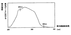
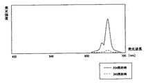
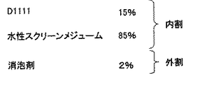
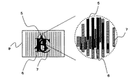
次に、実施例を用いて本発明を詳細に説明する。図1は、発光体D1111の励起スペクトルを示す。図2は、発光体D1111の発光スペクトルを示す。図3は、発光体D1111を使用して作製したインキの配合割合を示す。図4は、紫外線吸収特性又は反射特性を有する紫外線遮断剤の紫外線吸収特性を示す。図5は、本発明の一実施例における第1画像の画像Aと画像Bの配置を示す。図6は、本発明の一実施例における第2画像を示す。図7は、本発明の一実施例における第1画像と第2画像の印刷時の刷り合わせを示す。図8(a)は、本発明の一実施例における印刷物に対する可視光照射時の視認画像を示し、(b)は、長波の紫外線照射時の視認画像を示し、(c)は、短波の紫外線照射時の視認画像をそれぞれ示す。図9は、本発明の一実施例における第1画像の画像Aと画像Bの配置を示す。図10は、本発明の一実施例における第2画像を示す。図11は、本発明の一実施例における第1画像と第2画像の印刷時の刷り合わせを示す。図12は、図11に示す刷り合わせの側面図を示す。図13(a)は、本発明の一実施例における印刷物に対する可視光照射時の視認画像を、(b)は、長波の紫外線照射時の視認画像を、(c)は、短波の紫外線照射時の視認画像をそれぞれ示す。 Next, the present invention will be described in detail using examples. FIG. 1 shows the excitation spectrum of the illuminant D1111. FIG. 2 shows an emission spectrum of the illuminant D1111. FIG. 3 shows the blending ratio of the ink produced using the illuminant D1111. FIG. 4 shows the ultraviolet absorption characteristics of an ultraviolet blocking agent having ultraviolet absorption characteristics or reflection characteristics. FIG. 5 shows the arrangement of the images A and B of the first image in one embodiment of the present invention. FIG. 6 shows a second image in one embodiment of the present invention. FIG. 7 shows the alignment of the first image and the second image when printing according to an embodiment of the present invention. FIG. 8A shows a visual image when a printed material is irradiated with visible light in one embodiment of the present invention, FIG. 8B shows a visual image when irradiated with long-wave ultraviolet light, and FIG. 8C shows short-wave ultraviolet light. A visual image at the time of irradiation is shown. FIG. 9 shows the arrangement of image A and image B of the first image in one embodiment of the present invention. FIG. 10 shows a second image in one embodiment of the present invention. FIG. 11 shows the imprinting at the time of printing the first image and the second image in one embodiment of the present invention. FIG. 12 shows a side view of the imprinting shown in FIG. FIG. 13A is a visual image when a printed material is irradiated with visible light in one embodiment of the present invention, FIG. 13B is a visual image when irradiated with long-wave ultraviolet light, and FIG. Each of the visual images is shown.
この実施例において、本発明にかかわる画像形成体の組み込まれた印刷物ユーザは長波の紫外線を照射するUVランプ1及び短波の紫外線を照射するUVランプ2を照射してそれぞれの発光像を判定すると仮定している。長波の紫外線及び短波の紫外線を照射するランプは容易に入手可能であることがその選定理由の一つである。
In this embodiment, it is assumed that a printed product user incorporating an image forming body according to the invention irradiates a UV lamp 1 that emits long-wave ultraviolet light and a
まず、長波の紫外線で発光強度が弱く、短波の紫外線で発光強度が強い励起特性を有する発光体の中から、その発光強度が50倍以上の差異があるD1111(根本特殊化学製造)を選定した。D1111の励起特性を図1に、その発光分布を図2に示す。 First, D1111 (Neko Special Chemical Manufacturing), which has a difference in emission intensity of 50 times or more, was selected from phosphors having excitation characteristics in which the emission intensity was weak with long wave ultraviolet rays and the emission intensity was strong with short wave ultraviolet rays. . FIG. 1 shows the excitation characteristics of D1111 and FIG. 2 shows the emission distribution.
発光画線を成す第1画像はスクリーン印刷方式を用い、被印刷媒体は無蛍光コート紙を用いた。このD1111を図3に示す配合割合でスクリーンインキを作製した。顔料コンテントは15%とし、発光体D1111を水性メジューム(PAW−000メジューム 帝国インキ製造)に投入した後、補助剤としてシリコン系消泡剤を2%外割りで添加し、これを高速分散機(販売メーカ:特殊機械工業株式会社、製品名:ホモディスパ)を使用して回転数3000rpmで3分間攪拌を行いスクリーンインキ化した。 A screen printing method was used for the first image forming the luminous image line, and non-fluorescent coated paper was used as the printing medium. A screen ink was prepared using this D1111 in the blending ratio shown in FIG. The pigment content is 15%, and the illuminant D1111 is added to an aqueous medium (PAW-000 Medium Teikoku Ink Manufacturing Co., Ltd.), and then a silicone-based antifoaming agent is added in an extra 2% portion as an auxiliary agent. The product was screened by stirring for 3 minutes at a rotational speed of 3000 rpm using a sales maker: Special Machine Industry Co., Ltd., product name: Homodispa.
画線構成を決める前に200線/インチでグラデーションスケールを印刷し、事前に発光確認を行った。このグラデーションスケールに対してUVランプ1を照射したところ、網点面積率60%以下の場合には画線の発光が目視で観察不能であることを確認した。また、このグラデーションスケールに対してUVランプ2を照射したところ、網点面積率20%以上の場合には目視で発光が確認可能であることを確認した。また、UVランプ1を照射したときの網点面積率80%の領域と、UVランプ2を照射したときの網点面積率50%の領域の発光強度がほぼ同じ強度となることを確認した。
Before deciding the line composition, a gradation scale was printed at 200 lines / inch, and light emission was confirmed in advance. When the gradation scale was irradiated with the UV lamp 1, it was confirmed that the emission of the image line was not visually observable when the dot area ratio was 60% or less. Further, when the gradation scale was irradiated with the
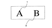
以上のことから、長波の紫外線で発光させる第1の画像の画像A(1)は網点面積率80%で構成し、短波の紫外線で発光させる第1の画像の画像B(2)は網点面積率50%で構成することとした。 From the above, the image A (1) of the first image that is emitted with long wave ultraviolet rays is configured with a dot area ratio of 80%, and the image B (2) of the first image that is emitted with short wave ultraviolet rays is the halftone dot area ratio. The point area ratio is 50%.
第2画像(3)を構成する紫外線吸収特性又は反射特性を有する紫外線遮断剤はマットニス(DIC製OPニス new championマット)を用いた。図4に紫外線吸収特性又は反射特性を有する紫外線遮断剤の紫外線吸収特性を示す。発明の効果を明確にするため、第2画像(3)の網点面積率は100%のベタ構成とした。 Matt varnish (DIC OP var new champion mat) manufactured by DIC was used as the ultraviolet blocking agent having ultraviolet absorption characteristics or reflection characteristics constituting the second image (3). FIG. 4 shows the ultraviolet absorption characteristics of an ultraviolet blocking agent having ultraviolet absorption characteristics or reflection characteristics. In order to clarify the effect of the invention, the halftone dot area ratio of the second image (3) is set to 100%.
刷り順としては、図5、図6及び図7に示すように、第1画像の画像A(1)と第1の画像の画像B(2)をスクリーン印刷方式で無蛍光コート紙(10)の異なった領域に印刷した後、第2画像(3)であるマットニスをオフセット印刷方式で第1画像の画像A(1)全体を被覆するように刷り重ね、印刷物(4)を作製する。 As the printing order, as shown in FIGS. 5, 6 and 7, the image A (1) of the first image and the image B (2) of the first image are non-fluorescent coated paper (10) by screen printing. After printing in the different areas, the mat varnish as the second image (3) is overprinted by the offset printing method so as to cover the entire image A (1) of the first image, thereby producing a printed matter (4).
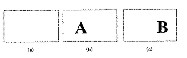
図8(a)に、可視光照射時の視認画像を、(b)に長波の紫外線照射時の視認画像を示し、(c)に短波の紫外線照射時の視認画像をそれぞれ示す。印刷物(4)に対してUVランプ1を用いて長波の紫外線を照射すると画像Aのみが赤色に発光し、画像Bの発光は目視で確認できず、UVランプ2を用いて短波の紫外線を照射すると画像Bのみが赤色に発光し、画像Aの発光は目視で確認できなかった。また、UVランプ1を用いて長波の紫外線を照射した場合の画像Aの発光と、UVランプ2を用いて短波の紫外線を照射した場合の画像Bの発光は目視確認においてほぼ同じ強度となっていることが確認できた。
FIG. 8A shows a visual image at the time of visible light irradiation, FIG. 8B shows a visual image at the time of long-wave ultraviolet irradiation, and FIG. 8C shows a visual image at the time of short-wave ultraviolet irradiation. When the printed matter (4) is irradiated with long-wave ultraviolet rays using the UV lamp 1, only the image A emits red light, and the emission of the image B cannot be visually confirmed, and the
本実施例は、画像の配置を特殊化することで画像Aと画像Bの画像のスイッチが、あたかも同一位置で発生しているかのごとく観察者に見せるものであり、同時に可視光下においても同一位置に有意の画像を施した例である。この例においても、ユーザは長波の紫外線を照射するUVランプ1及び短波の紫外線を照射するUVランプ2を照射してそれぞれの発光像を判定すると仮定している。
In this embodiment, by specializing the arrangement of the images, the switches of the images A and B are shown to the observer as if they were generated at the same position, and at the same time, the same even under visible light. This is an example in which a significant image is applied to the position. Also in this example, it is assumed that the user irradiates the UV lamp 1 that irradiates long-wave ultraviolet light and the
実施例1同様に長波の紫外線及び短波の紫外線を照射するランプは容易に入手可能であることがその選定理由の一つである。発光体は実施例1同様にD1111(根本特殊化学製造)を選定した。 One of the reasons for selection is that lamps that irradiate long-wave ultraviolet rays and short-wave ultraviolet rays are easily available as in the first embodiment. D1111 (Nemoto Special Chemical Manufacturing Co., Ltd.) was selected as the light emitter as in Example 1.
発光画線を成す第1画像はスクリーン印刷方式を用い、被印刷媒体は無蛍光コート紙を用いた。このD1111を実施例1と同様な配合割合でスクリーンインキを作製した。実施例1と同様に長波の紫外線で発光させる第1画像の画像A(5)は網点面積率80%で構成し、短波の紫外線で発光させる第1画像の画像B(6)は網点面積率50%で構成した。 A screen printing method was used for the first image forming the luminous image line, and non-fluorescent coated paper was used as the printing medium. A screen ink was prepared using this D1111 in the same proportion as in Example 1. As in the first embodiment, the first image A (5) emitted with long wave ultraviolet rays is composed of a dot area ratio of 80%, and the first image B (6) emitted with short wave ultraviolet rays is halftone dot. The area ratio was 50%.
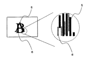
第2画像(7)を構成する紫外線吸収特性又は反射特性を有する紫外線遮断剤はマットニス(DIC製OPニス new championマット)にアサヒ化成工業(株)製のTrans. Blue DR4を4%混合し、有色画線化した。また、第2画像を有意化するために、画線幅に大小を設けて万線模様(8)の中に「C」という記号を組み込んだ。発明の効果を明確にするため、第2画像(7)の網点面積率は100%のベタ構成とした。 The ultraviolet blocking agent having ultraviolet absorption characteristics or reflection characteristics constituting the second image (7) is mat. Varnish (DIC OP var new champion mat) or Asahi Kasei Kogyo Co., Ltd. Trans. 4% of Blue DR4 was mixed to make a colored image line. Further, in order to make the second image significant, the line width was made large and small, and the symbol “C” was incorporated in the line pattern (8). In order to clarify the effect of the invention, the halftone dot area ratio of the second image (7) is a solid composition of 100%.
刷り順としては、図9、図10、図11及び図12に示すように、第1画像の画像A(5)と第1画像の画像B(6)をスクリーン印刷方式で無蛍光コート紙(10)の同一領域内に印刷した後、第2画像(7)であるマットニスをオフセット印刷方式で第1画像の画像A(5)の画線上に刷り重ね、印刷物(9)を作製する。ここでいう同一領域内とは、目視では確認が困難な程度に極めて隣接している異なった領域のことを示している。 As shown in FIGS. 9, 10, 11, and 12, the first image A (5) and the first image B (6) are screen-printed with a non-fluorescent coated paper ( After printing in the same area of 10), the mat varnish which is the second image (7) is overprinted on the image line of the image A (5) of the first image by the offset printing method to produce a printed matter (9). The term “in the same region” as used herein refers to different regions that are extremely adjacent to the extent that it is difficult to confirm visually.
図13(a)に可視光照射時の視認画像を示し、(b)に長波の紫外線照射時の視認画像を示し、(c)に短波の紫外線照射時の視認画像を示す。印刷物に対してUVランプ1を用いて長波の紫外線を照射すると画像Aのみが赤色に発光し、画像Bの発光は目視で確認できず、UVランプ2を用いて短波の紫外線を照射すると画像Bのみが赤色に発光し、画像Aの発光は目視で確認できなかった。また、UVランプ1を用いて長波の紫外線を照射した場合の画像Aの発光と、UVランプ2を用いて短波の紫外線を照射した場合の画像Bの発光は目視確認においてほぼ同じ強度となっていることが確認できた。
FIG. 13A shows a visual image when irradiated with visible light, FIG. 13B shows a visual image when irradiated with long-wave ultraviolet light, and FIG. 13C shows a visual image when irradiated with short-wave ultraviolet light. When the printed matter is irradiated with long-wave ultraviolet rays using the UV lamp 1, only the image A emits red light, and the emission of the image B cannot be visually confirmed. When the
本実施例1及び2では、第1の波長(短波)の紫外線照射により可視光領域で発光する発光強度が、第2の波長(長波)の紫外線照射により可視光領域で発光する発光強度の50倍以上ある発光体、D1111を選定した。その発光体によって網点面積率80%と50%の画像を印刷し、紫外線短波遮断剤を網点面積率80%の画像の上に被覆し、長波の紫外線と短波の紫外線で画像を変化させた。この場合、長波の紫外線照射と中波の紫外線照射、又は中波の紫外線照射と短波の紫外線照射で画像変化させることは、紫外線吸収特性又は反射特性を有する紫外線遮断剤の被覆厚さを厚くし、その波長を吸収又は反射する特性を有する紫外線遮断剤を選択することで容易に可能である。 In Examples 1 and 2, the light emission intensity emitted in the visible light region when irradiated with ultraviolet rays having the first wavelength (short wave) is 50, which is the light emission intensity emitted in the visible light region when irradiated with ultraviolet rays of the second wavelength (long wave). D1111, a light emitter that is more than doubled, was selected. Images with 80% and 50% halftone dot area ratio are printed by the phosphor, and an ultraviolet shortwave blocking agent is coated on the image with 80% halftone dot area ratio, and the image is changed with long wave ultraviolet light and short wave ultraviolet light. It was. In this case, changing the image by irradiation with long wave ultraviolet light and medium wave ultraviolet light, or medium wave ultraviolet light irradiation and short wave ultraviolet light irradiation increases the coating thickness of the ultraviolet blocking agent having ultraviolet absorption characteristics or reflection characteristics. It is easily possible by selecting an ultraviolet blocking agent having the property of absorbing or reflecting the wavelength.
さらに、第1の波長の紫外線照射により可視光領域で発光する発光強度と、第2の波長の紫外線照射により可視光領域で発光する発光強度との差が20倍以上であれば良く、本実施例では第1の波長が短波で第2の波長が長波だが、他に、第1の波長が中波で第2の波長が長波、第1の波長が長波で第2の波長が短波である、といった発光体を選定することも可能である。 Furthermore, it is sufficient that the difference between the light emission intensity emitted in the visible light region by the ultraviolet irradiation of the first wavelength and the light emission intensity emitted in the visible light region by the ultraviolet irradiation of the second wavelength is 20 times or more. In the example, the first wavelength is a short wave and the second wavelength is a long wave. In addition, the first wavelength is a medium wave, the second wavelength is a long wave, the first wavelength is a long wave, and the second wavelength is a short wave. It is also possible to select a light emitter such as.
選定した発光体によって二つ以上の印刷画像の画像面積率に差を持たせ、それによって印刷画像を被覆する紫外線吸収剤の選定も重要となってくる。つまり、最初に選定する発光体によって、印刷する画像の画線面積率、更には被覆する紫外線吸収剤の選定が決定されることとなり、これらのバランスを調整しなければ本発明の効果はあり得ない。 Depending on the selected light emitter, the image area ratio of two or more printed images has a difference, and accordingly, the selection of an ultraviolet absorber that covers the printed images becomes important. In other words, the line area ratio of the image to be printed and the selection of the UV absorber to be coated are determined by the light emitting body to be selected first. If these balances are not adjusted, the effect of the present invention can be obtained. Absent.
さらに、本実施例では一種類の発光体のみを使用したが、ニつの紫外線波長において強度が大きく異なる発光体であれば、網点面積や画線幅、ピッチ等の画線構成を変更することで同様な効果を得ることが可能である。 Furthermore, in this example, only one type of illuminant was used. However, if the illuminant has greatly different intensities at two ultraviolet wavelengths, the image line configuration such as halftone dot area, image line width, and pitch can be changed. It is possible to obtain a similar effect.
また、励起特性の異なる複数の発光体の配合割合をユーザが調整することも同様に、本発明に適合する励起特性の発光体を任意に作り出すことも可能である。同時に、使用する発光体に二色の発光を示す発光体を使用することで、画像変化のみならず発光色の変化を付与可能であり、これらは本発明の範疇であることは言うまでもない。 In addition, the user can adjust the blending ratio of a plurality of light emitters having different excitation characteristics, and it is also possible to arbitrarily create a light emitter having excitation characteristics suitable for the present invention. At the same time, it is possible to give not only a change in image but also a change in luminescent color by using a luminescent material that emits light of two colors as a luminescent material to be used, and it goes without saying that these are within the scope of the present invention.
もともと、二色の発光を示す発光体は色相と励起特性の異なる発光体の発光強度の変化を利用した発光体であることから、本発明の発光体が要求する特性を有している場合が多い。 Originally, an illuminant that emits light of two colors is an illuminant that utilizes a change in luminescence intensity of an illuminant having different hue and excitation characteristics, and thus may have the characteristics required by the illuminant of the present invention. Many.
二つの実施例においては、それぞれの波長域で発光をスイッチさせる画像は網点面積率の異なる発光画線によってそれぞれ構成したが、本発明は網点面積率の違いに限定されるものではなく、発光像の画線幅や画線ピッチ、分断ピッチ、分岐ピッチ等の違いによっても当然実施することが可能であり、これらの画線技術を用いた画像形成物も本発明の範疇であることは言うまでもない。 In the two examples, the images for switching the light emission in the respective wavelength regions are configured by light emission lines having different dot area ratios, but the present invention is not limited to the difference in the dot area ratios. Of course, it is possible to carry out depending on differences in the line width, line pitch, segmentation pitch, branching pitch, etc. of the luminescent image, and image formation using these image line technologies is also within the scope of the present invention. Needless to say.
1 第1の画像の画像A(網点面積率80%)
2 第1の画像の画像B(網点面積率50%)
3 第2の画像(網点面積率100%)
4 印刷物
5 第1の画像の画像A(網点面積率80%)
6 第1の画像の画像B(網点面積率50%)
7 第2の画像(網点面積率100%)
8 部分的に幅を太らせた箇所
9 印刷物
10 基材(無蛍光コート紙)
1 Image A of first image (halftone dot area ratio 80%)
2 Image B of the first image (halftone dot area ratio 50%)
3 Second image (dot area ratio 100%)
4
6 Image B of first image (half-tone dot area ratio 50%)
7 Second image (dot area ratio 100%)
8 Partially thickened portion 9 Printed
Claims (3)
前記第1の印刷画像は前記第2の印刷画像よりも画像面積率が高く、前記第1の印刷画像と前記第2の印刷画像は、紫外線領域で発光強度が異なる特性を有する同一の発光インキで印刷し、
第1の波長の紫外線が、第2の波長の紫外線より短い波長であって、
前記発光インキは、前記第1の波長の紫外線照射により可視光領域で発光する発光強度が、前記第2の波長の紫外線照射により可視光領域で発光する発光強度の少なくとも20倍を有し、
前記紫外線遮断剤は、紫外線照射により前記第1の波長の紫外線を遮断する遮断率が、前記第2の波長の紫外線を遮断する遮断率よりも高い特性を有することを特徴とする画像形成体。 An image forming body in which a first printing image and a second printing image are formed on a substrate, and a concealing layer for concealing the first printing image with an ultraviolet blocking agent is formed,
The first printed image has an image area ratio higher than that of the second printed image, and the first printed image and the second printed image have the same emission light intensity in the ultraviolet region. Print with
The ultraviolet light of the first wavelength is shorter than the ultraviolet light of the second wavelength,
The luminescent ink has a light emission intensity that emits light in the visible light region when irradiated with ultraviolet light of the first wavelength, and has a light emission intensity that emits light in the visible light region when irradiated with ultraviolet light of the second wavelength,
The image forming body, wherein the ultraviolet blocking agent has a characteristic that a blocking rate for blocking ultraviolet rays of the first wavelength by ultraviolet irradiation is higher than a blocking rate for blocking ultraviolet rays of the second wavelength.
前記第1の印刷画像は前記第2の印刷画像よりも画像面積率が高く、前記第1の印刷画像と前記第2の印刷画像は、紫外線領域で発光強度が異なる特性を有する同一の発光インキで印刷し、
第1の波長の紫外線が、第2の波長の紫外線より長い波長であって、
前記発光インキは、第2の波長の紫外線照射により可視光領域で発光する発光強度が、第1の波長の紫外線照射により可視光領域で発光する発光強度の少なくとも20倍を有し、
前記紫外線遮断剤は、紫外線照射により前記第2の波長の紫外線を遮断する遮断率が、前記第1の波長の紫外線を遮断する遮断率よりも高い特性を有することを特徴とする画像形成体。 An image forming body in which a first printing image and a second printing image are formed on a substrate, and a concealing layer for concealing the first printing image with an ultraviolet blocking agent is formed,
The first printed image has an image area ratio higher than that of the second printed image, and the first printed image and the second printed image have the same emission light intensity in the ultraviolet region. Print with
The first wavelength of ultraviolet light is longer than the second wavelength of ultraviolet light,
The light-emitting ink has a light emission intensity that emits light in the visible light region when irradiated with ultraviolet light of the second wavelength, and has a light emission intensity that emits light in the visible light region when irradiated with ultraviolet light of the first wavelength;
The image forming body, wherein the ultraviolet blocking agent has a characteristic that a blocking rate for blocking ultraviolet rays of the second wavelength by ultraviolet irradiation is higher than a blocking rate for blocking ultraviolet rays of the first wavelength.
The image area ratio formed by configuring the first print image area and the second print image area is an image formed by a halftone dot area ratio formed by halftone dots and / or a plurality of image lines. The image forming body according to claim 1, wherein the image forming body has a line area ratio.
Priority Applications (1)
| Application Number | Priority Date | Filing Date | Title |
|---|---|---|---|
| JP2005180131A JP4635170B2 (en) | 2005-06-21 | 2005-06-21 | Image forming body |
Applications Claiming Priority (1)
| Application Number | Priority Date | Filing Date | Title |
|---|---|---|---|
| JP2005180131A JP4635170B2 (en) | 2005-06-21 | 2005-06-21 | Image forming body |
Publications (2)
| Publication Number | Publication Date |
|---|---|
| JP2007001018A JP2007001018A (en) | 2007-01-11 |
| JP4635170B2 true JP4635170B2 (en) | 2011-02-16 |
Family
ID=37687061
Family Applications (1)
| Application Number | Title | Priority Date | Filing Date |
|---|---|---|---|
| JP2005180131A Expired - Fee Related JP4635170B2 (en) | 2005-06-21 | 2005-06-21 | Image forming body |
Country Status (1)
| Country | Link |
|---|---|
| JP (1) | JP4635170B2 (en) |
Cited By (1)
| Publication number | Priority date | Publication date | Assignee | Title |
|---|---|---|---|---|
| JP2015009521A (en) * | 2013-07-01 | 2015-01-19 | 独立行政法人 国立印刷局 | Luminescent printed matter |
Family Cites Families (3)
| Publication number | Priority date | Publication date | Assignee | Title |
|---|---|---|---|---|
| JPH10129107A (en) * | 1996-11-01 | 1998-05-19 | Toppan Printing Co Ltd | Image display |
| JP3828632B2 (en) * | 1997-03-11 | 2006-10-04 | 大日本印刷株式会社 | Fluorescent image formation |
| JPH10250211A (en) * | 1997-03-13 | 1998-09-22 | Dainippon Printing Co Ltd | Fluorescent image formation |
-
2005
- 2005-06-21 JP JP2005180131A patent/JP4635170B2/en not_active Expired - Fee Related
Cited By (1)
| Publication number | Priority date | Publication date | Assignee | Title |
|---|---|---|---|---|
| JP2015009521A (en) * | 2013-07-01 | 2015-01-19 | 独立行政法人 国立印刷局 | Luminescent printed matter |
Also Published As
| Publication number | Publication date |
|---|---|
| JP2007001018A (en) | 2007-01-11 |
Similar Documents
| Publication | Publication Date | Title |
|---|---|---|
| CA2507900C (en) | Security device and its production method | |
| RU2264296C2 (en) | Half-tint image, produced by printing method | |
| MX2007005456A (en) | Substrate fluorescence mask for embedding information in printed documents. | |
| JP3430755B2 (en) | Anti-counterfeit printing | |
| JP4487090B2 (en) | Luminous printed matter with authenticity discrimination | |
| JP2003276299A (en) | Latent image forming method by double tone printing and printed matter thereof | |
| JP6075230B2 (en) | Luminescent printed matter | |
| RU2376148C2 (en) | Protective element for protected documents | |
| JP4635170B2 (en) | Image forming body | |
| JP4552052B2 (en) | Multicolor luminescent mixture, multicolor luminescent ink composition, and image formed product | |
| JPH1076745A (en) | Anti-counterfeit printing | |
| JP5597875B2 (en) | Latent image printed matter | |
| JP2005138399A (en) | Forgery preventing slip | |
| JP3931548B2 (en) | Concealment information forming body | |
| JP6124254B2 (en) | Luminescent printed matter | |
| JP4649613B2 (en) | True / false discrimination printed matter | |
| JP3271474B2 (en) | Anti-counterfeit printing | |
| JP5533484B2 (en) | Printed material having latent image | |
| JP5888697B2 (en) | Luminescent printed matter | |
| JP7537179B2 (en) | Fluorescent prints | |
| HK1076776B (en) | Security device and its production method | |
| JPH09254572A (en) | card | |
| JP2017202643A (en) | Printed matter using ink containing light condensing fluorescent dye |
Legal Events
| Date | Code | Title | Description |
|---|---|---|---|
| A621 | Written request for application examination |
Free format text: JAPANESE INTERMEDIATE CODE: A621 Effective date: 20071018 |
|
| A977 | Report on retrieval |
Free format text: JAPANESE INTERMEDIATE CODE: A971007 Effective date: 20100408 |
|
| TRDD | Decision of grant or rejection written | ||
| A01 | Written decision to grant a patent or to grant a registration (utility model) |
Free format text: JAPANESE INTERMEDIATE CODE: A01 Effective date: 20101026 |
|
| A01 | Written decision to grant a patent or to grant a registration (utility model) |
Free format text: JAPANESE INTERMEDIATE CODE: A01 |
|
| A61 | First payment of annual fees (during grant procedure) |
Free format text: JAPANESE INTERMEDIATE CODE: A61 Effective date: 20101026 |
|
| FPAY | Renewal fee payment (event date is renewal date of database) |
Free format text: PAYMENT UNTIL: 20131203 Year of fee payment: 3 |
|
| R150 | Certificate of patent or registration of utility model |
Free format text: JAPANESE INTERMEDIATE CODE: R150 |
|
| LAPS | Cancellation because of no payment of annual fees | ||
| S531 | Written request for registration of change of domicile |
Free format text: JAPANESE INTERMEDIATE CODE: R313531 |