JP4635143B2 - Gear finishing by synchronous drive - Google Patents
Gear finishing by synchronous drive Download PDFInfo
- Publication number
- JP4635143B2 JP4635143B2 JP2003114679A JP2003114679A JP4635143B2 JP 4635143 B2 JP4635143 B2 JP 4635143B2 JP 2003114679 A JP2003114679 A JP 2003114679A JP 2003114679 A JP2003114679 A JP 2003114679A JP 4635143 B2 JP4635143 B2 JP 4635143B2
- Authority
- JP
- Japan
- Prior art keywords
- forming tool
- workpiece
- spindle
- control motor
- main shaft
- Prior art date
- Legal status (The legal status is an assumption and is not a legal conclusion. Google has not performed a legal analysis and makes no representation as to the accuracy of the status listed.)
- Expired - Fee Related
Links
Images


Landscapes
- Gear Processing (AREA)
Description
【0001】
【発明の属する技術分野】
本発明は、被研削歯車と仕上げ用成形工具とを駆動により同期回転させながら研削を行なう歯車仕上げ加工方法に関する。
【0002】
【従来の技術】
歯車に対しシェービング、ホーニング(ドレッシングを含む)等の仕上げ加工をする際には、内歯又は外歯の歯車状をした回転砥石又はカッター等の仕上げ用成形工具を使用し、被研削歯車と噛合させ、歯面同士のすべり接触を利用して研削を行なう。
【0003】
通常の場合、成形工具が駆動され被研削歯車は成形工具との噛合の下に、成形工具に伴われて回転する、いわゆる連れ回り状態で加工される。但し、連れ回り状態での研削では被研削歯車の偏心や累積ピッチ誤差を強制的に修正する機構を持たず、その結果、高い精密度の加工が困難である。
【0004】
これに対し、成形工具と被研削歯車との双方を駆動させつつ加工することにより、高い精度を得ることが可能となる。但し、これには、バックラッシュが零の状態で歯同士を噛合させる必要上、成形工具と被研削歯車とを高精度で同期回転させることが不可欠である。
【0005】
高精度の同期回転を実現するため、種々の提案がなされてきたが、成形工具及び被研削歯車を停止さた状態で噛合させ、正逆回転を僅かずつ繰り返すなどして、切り込み方向への移動を行ない位相が合った状態を得てから、双方を駆動して同期回転させる形態が一般的である。例えば、特許第3000668号に係る加工方法においては、被研削歯車を微少量ずつ正回転及び逆回転させ、各回転方向において成形工具が連れ回りを始める回転変位量を検出し、位相ずれを零にするのに必要な成形工具の位置補正量を求め、その位置補正量に基づいて送りモータにより成形工具に送りを与えて位相の合った同期回転が得られる。
【0006】
しかしながら、これらの方法では、センサによる成形工具との相対位置の検出を行なうために被研削歯車の微小回転を繰り返さねばならず、手間と時間を必要とするという欠点があった。
【0007】
【発明が解決しようとする課題】
本発明は、同期回転による歯車の仕上げ加工を行なう際に、手間の掛かる成形工具の微小回転の繰り返しを必要とすることなく被研削歯車及び成形工具の回転を開始することができる歯車仕上げ加工方法を提供することを目的とする。
【0008】
【課題を解決するための手段】
本発明は、前記目的を達成するため、ワークである歯車を成形仕上げ加工するにあたり、機台に支持されたワーク支持用の主軸及び仕上げ用成形工具の双方を同期回転するように駆動する歯車仕上げ加工方法であって、前記主軸及び成形工具の制御モータによる駆動を、サーボモータによるサーボ制御又はACスピンドルモータによるCs制御により行なうものとし、該歯車仕上げ加工方法は、前記制御モータの回転方向原点への移動並びに前記主軸及び心押し軸に対するワークの取付けを、心押し軸の回転非クランプ状態で行なうステップと、ワーク位置決め装置をワークと噛合させてワークの回転方向位置決めを行なうステップと、ワークを前記ワーク位置決め装置と噛合させた状態で前記心押し軸を回転クランプ状態とするステップと、前記主軸に結合された制御モータをフリーラン状態とするステップと、フリーラン状態に伴って生じる前記主軸における制御モータ側の主軸側に対する位相ずれを読み取るステップと、前記ワーク位置決め装置をワークから外すステップと、前記位相ずれを解消するように、前記主軸に結合された制御モータ及び前記成形工具に結合された制御モータの一方の駆動位相を修正し、前記主軸及び前記成形工具を各制御モータにより同期させ且つ位相を合わせて回転させるステップと、ワーク及び前記成形工具の歯先円が相互に交わる程度に前記主軸及び前記成形工具を接近させるステップと、前記主軸に結合された制御モータ及び前記成形工具に結合された制御モータの一方の制御モータの駆動トルクを前記成形工具による切削が生じない程度に低下させた状態で、バックラッシュ零として予め設定された位置又は検知される位置まで前記主軸と前記成形工具とを接近させるステップと、前記バックラッシュ零の位置において前記主軸及び成形工具の各制御モータ間の位相ずれを検出しこれを解消するように駆動位相を修正し、前記各制御モータの駆動位相を固定するステップと、各制御モータを切削に必要なトルクで駆動し前記主軸及び前記成形工具を同期回転させつつ切り込み量を漸増させて仕上げ切削を行なうステップとを備えていることを特徴とする歯車仕上げ加工方法を提供するものである(第1発明)。
【0009】
本発明はまた、前記目的を達成するため、ワークである歯車を成形仕上げ加工するにあたり、機台に支持されたワーク支持用の主軸及び仕上げ用成形工具の双方を同期回転するように駆動する歯車仕上げ加工方法であって、前記主軸及び成形工具の制御モータによる駆動を、サーボモータによるサーボ制御又はACスピンドルモータによるCs制御により行なうものとし、該歯車仕上げ加工方法は、手動にてワークと前記成形工具とを僅かのバックラッシュを付けた状態で噛み合わせ、該ワークを前記主軸と心押し軸とによりクランプするステップと、前記主軸に結合された制御モータ及び前記成形工具に結合された制御モータの一方の駆動トルクを前記成形工具による切削が生じない程度に低下させた状態で、前記主軸及び成形工具を各制御モータの制御により同期回転させるステップと、バックラッシュ零として予め設定された位置又は検知される位置まで前記主軸と前記成形工具とを接近させるステップと、前記バックラッシュ零の位置における前記主軸と前記成形工具との各制御モータの同期誤差を検出し、修正後、駆動位相を固定するステップと、各制御モータを切削に必要なトルクで駆動し前記主軸及び前記成形工具を同期回転させつつ切り込み量を漸増させて仕上げ切削を行なうステップとを備えていることを特徴とする歯車仕上げ加工方法を提供するものである(第2発明)。
【0010】
【作用】
本発明中、第1発明においては、ワークである歯車を研削仕上げ加工するにあたり、主軸及び成形工具の駆動は、サーボモータによるサーボ制御又はACスピンドルモータをCs制御(c軸制御すなわちz軸回りの回転角制御)により行なうものとし、先ず、制御モータの回転方向原点への移動並びに前記主軸及び心押し軸に対するワークの取付けを行なう(一次位相決め)。
【0011】
そして、ワーク位置決め装置を主軸上のワークと噛合させて回転方向の位置決めを行ない且つ主軸と心押し軸とによりワークをクランプする。ワーク位置決め装置は、主軸(制御モータ回転軸)の回転方向原点に対応するワークの位相を位置出しするようにワークと噛合する。制御モータが原点に設定されていても、実際にはワークの位相は、取付け誤差等によるずれを生じている。したがって、この状態において主軸は、ワーク位置決め装置により拘束されたワーク側と、制御モータにより拘束された制御モータ側との間において僅かなねじれを生じている。この状態で制御モータをフリーラン状態とすると、主軸における制御モータ側が、そのねじれ分だけ僅かに回転する。この回転による位相ずれを読み取り、その位相ずれを解消するように基準位置を調整する等して、駆動位相を修正すれば、主軸及び成形工具を各制御モータの制御により同期させ且つ位相を合わせて回転させることができる(二次位相決め)。なお、この駆動位相の修正は、前記主軸に結合された制御モータ及び前記成形工具に結合された制御モータのいずれか一方において行なうことができる。
【0012】
したがって、この状態で、研削に必要な駆動力でワークを回転させながら成形工具に噛合させることもできるが、より正確な位相合わせを得るためにさらに、以下の操作を行なう。先ず、ワーク及び前記成形工具の歯先円が相互に交わる程度に主軸及び成形工具を接近させる。次に、前記一方の制御モータの駆動トルクを成形工具による切削を受けない程度に低下させた状態で、バックラッシュ零として予め設定された位置又は検知される位置まで主軸と成形工具とを接近させ、その状態において前記主軸及び成形工具の各制御モータ間の位相ずれを検出しこれを解消するように駆動位相を修正し、各制御モータの駆動位相を固定する。これにより、位置決め装置と成形工具との間に不可避的に生じる位相誤差をも解消し、ワークと成形工具との位相が正確に一致させることができる(三次位相決め)。
【0013】
この状態で、各制御モータを切削に必要なトルクに戻し、切り込み量を漸増させて切削を行なえば、同期駆動による極めて高い精度の仕上げ切削を行なうことができるのである。
【0014】
なお、成形工具の位相は、成形工具の歯又は溝の位置を読み取るエンコーダにより検知される。したがって、成形工具をヘッドに新たに取り付けたときは、成形工具を停止させ、手動モードで主軸上のワークと噛合させ、ワーク全周での噛合が均一化された状態で、成形工具の位相の原点を設定する。
【0015】
本発明中、第2発明においては、手動にてワークと前記成形工具とを僅かのバックラッシュを付けた状態で噛み合わせ、該ワークを前記主軸と心押し軸とによりクランプする。これにより、ワークは、成形工具に対してほぼ位相が一致した状態に置かれ、且つ主軸と心押し軸とによるクランプ状態で保持される。ここでは、成形工具及び主軸を停止させた状態で作業を行なうので、後の駆動回転を妨げないように、僅かのバックラッシュを付けた状態の噛合に留める。
【0016】
次に、主軸に結合された制御モータ及び成形工具に結合された制御モータの一方の駆動トルクを成形工具による切削が生じない程度に低下させた状態で、主軸及び成形工具を各制御モータの制御により同期回転させる。このように一方の制御モータをトルク低下させた状態で、同期回転させるので、主軸及び成形工具の一方は、他方に伴われて回転(連れ回り)する。この状態で、バックラッシュ零として予め設定された位置又は検知される位置まで前記主軸と前記成形工具とを接近させる。この状態において、一方の制御モータは、トルクは低いが駆動されているので、両制御モータは、目的とする同期駆動に近い状態で、位相が正確に一致する。ここで、バックラッシュ零の位置における主軸及び成形工具の各制御モータの同期誤差を検出し、修正後、駆動位相を固定する。これにより、正確に一致した位相での同期駆動が可能となる。
【0017】
この状態で、各制御モータを切削に必要なトルクで駆動し前記主軸及び前記成形工具を同期回転させつつ切り込み量を漸増させて切削を行なえば、同期駆動による極めて高い精度の仕上げ切削を行なうことができる。
【0018】
【発明の実施の形態】
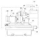
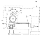
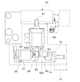
以下、本発明の実施例につき、添付図面を参照しつつ説明する。図1,図2,図3は、各々本発明の一実施形態に掛かる歯車仕上装置の正面図、側面図、平面図である。
【0019】
図示の歯車仕上装置は、機台Bに支持されたテーブル10上で、保持装置により被研削歯車(ワーク)Wを保持するようになっている。保持装置は、テーブル上で相互に接近離反するように摺動可能でありワークを支持するための主軸及び心押し軸を各々有するヘッドストック30,心押し台40を備えている。機台Bにはさらに、砥石保持装置50が装着されている。
【0020】
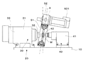
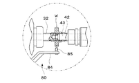
図4は、この歯車仕上装置の動作部分を中心に示す正面図である。図示のように、一方(図において左)のヘッドストック30は、テーブル10に支持された主軸台本体31と、該主軸台本体により回転可能に支持された主軸32と、主軸台本体31に結合され該主軸32を回転させる駆動モータ33とを備えている。他方(図において右)の心押し台40は、テーブル10に支持された心押し台本体41と、該心押し台本体により回転可能に支持された心押し軸42とを備えている。
【0021】
図5に示すように、心押し軸42は、心押し台本体41に装着された図外の駆動装置により軸方向に進退動するクランプ軸を軸内部に備えている。したがって、クランプ軸を後退させた状態で主軸32及び心押し軸42によりワークWを支持し、その後クランプ軸を前進させることにより、これらの軸上でワークWを回転方向にクランプすることができる。ワーク駆動モータ33は、以下に述べる制御を可能にするように、この例ではビルトインACスピンドルモータとされている。
【0022】
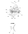
砥石保持装置50は、図に示すように、ヘッドストック30と心押し台40との間に位置し回転砥石51を支持するリング状のヘッド52と、該ヘッド52を主軸32に垂直な水平軸線回りに回動可能に支持する保持部53とを備えている。このように、この実施形態においては、成形工具として回転砥石51が使用されている。図2及び図3に示すように、保持部53は、ヘッド52を主軸の回りに回転させるためのヘッド駆動モータ531、及びヘッド52を主軸32に垂直な水平軸線回りに回動するためのヘッド傾動モータ532を備えている。ヘッド駆動モータ531の出力軸に固定された歯車533には、中間歯車534,535が噛合し、これらの中間歯車は、ヘッド52の外周に設けられた歯に噛合してヘッド52を駆動する。このように、駆動歯車に噛合する2個の中間歯車を介してヘッド52の外周ギアを駆動することにより、簡単な構造でローバックラッシュを実現し、高精度、高速での同期噛合を確実にする。ヘッド駆動モータ531は、以下に述べる制御を可能にするように、この例ではACスピンドルモータとされている。砥石保持装置50には、機台上の切り込み駆動部60が結合されている。切り込み駆動部60は、水平駆動モータ61の駆動により主軸32,心押し軸42に垂直な水平軸線に沿って移動可能であり、その移動によりヘッド52及び回転砥石51を主軸上のワークに接近離反させ、研削の際には切り込みを行なわせる。
【0023】
なお、上記ヘッドストック30,心押し台40、ワーク駆動モータ33、ヘッド駆動モータ531等の移動や回転の制御は、操作盤71を備えた制御装置70により行なわれる。
【0024】
ワークの交換から主軸及び成形工具の同期駆動の開始までを自動で行なう歯車仕上装置の場合、ヘッドストック30には、ワーク位置決め装置80が取り付けられている。ワーク位置決め装置は、成形工具との正確な噛合を得るためにワークの回転方向の正確な位置決めを行なうものであり、例えば以下のような構成とすることができる。ワーク位置決め装置80は、図6に示すように、ヘッドストック30におけるワーク取付側端部にボルトにより締結された固定部81を備え、該固定部上のスライドガイド82に摺動可能にアーム取付台83が装着されている。アーム84は、基端部をアーム取付台83に固定され、先端部には、ワークWの歯の間に進入し得る大きさの円錐状突起85が取り付けられている。さらに、固定部81には、駆動シリンダ86が取り付けられ、これと協働するピストンロッド87がアーム基端部に結合されている。したがって、アーム84は、駆動シリンダ86により駆動され、スライドガイド82により案内されて、主軸32の径方向に摺動する。固定部81にはドックプレート88が固定され、該ドックプレートにアームの前進後退端検出用の近接スイッチ89が取り付けられている。これにより、アーム84は、ワークWに噛合する前進位置とその噛合を解く後退位置との間を進退動する。前進時にアーム先端の突起85は、図6のa部詳細図に示すように、ワークWの歯と噛合し、ワークの回転方向の位置決めを行なう。
【0025】
なお、ワークの交換から主軸及び成形工具の同期駆動の開始までを手動操作を交えて行なう歯車仕上装置の場合には、ワーク位置決め装置80を省略することができる。
【0026】
ワーク駆動モータ33及びヘッド駆動モータ521としては、前述のように回転方向の同期及び位相の正確な制御ができる制御モータが使用され、具体的にはサーボモータ又はACスピンドルモータとされる。
【0027】
次に、この歯車仕上装置のより詳細な構成、及びこれに基づく加工方法の手順を、自動化を基本とする形態と、手動操作を交えて行なう形態とについて説明する。
【0028】
I. ワークの交換から主軸及び成形工具の同期駆動の開始までを自動化を基本として行なう場合
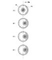
以下、図7の要部説明図及び図8のフローチャートを参照しつつ説明する。なお、この形態は、操作の自動化に有利であるが、必要に応じて手動操作を取り入れることも可能である。回転砥石51の位相は、回転砥石の歯又は溝の位置を読み取るエンコーダにより検知される。なお、回転砥石51をヘッド52に新たに取り付けたときは、回転砥石を停止させ、手動モードで主軸上のワークと噛合させ、ワーク全周での噛合が均一化された状態で、回転砥石の位相の原点を設定する。同じ回転砥石51を続けて使用する場合は、回転砥石を停止することなく原点の設定はそのまま使用することができる。
【0029】
この準備ができた後、ヘッドストック30のワーク駆動モータ33をエンコーダにおける原点に復帰した状態にすることにより、ワーク駆動モータ33をサーボロック状態になる(ステップ1)。
【0030】
この後、ヘッド駆動モータ532を作動させてヘッド52を駆動する。ヘッド52の回転速度は、ワークWの切削速度に適合したものとされる。ヘッドは、以後において停止指令が出るまで回転を続ける。その状態で、心押し台40をヘッドストック30に接近させ、主軸32及び心押し軸42によりワークWを保持する。ここでは、心押し軸42のクランプ軸は後退位置とされ、回転に対して非クランプ状態となっている(ステップ2)。
【0031】
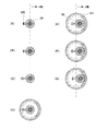
次にワーク位置決め装置80のアーム82を移動し、突起85をワークWの歯の間に進入させることにより、ワークWの回転方向の位置決めをする。主軸32上のワークWは、ワークWの機械加工精度のバラツキ、熱処理による歪み、治具への取付誤差等から、ワークW自身の位相と駆動モータの位相とが必ずしも一致しない。そこで、ワーク位置決め装置80により、ワークW自身の位相を正確に決めるのである(図7A)(ステップ3)。
【0032】
この突起85との噛合状態を保ったまま、心押し軸42のクランプ軸を前進させ、主軸32及び心押し軸42上でワークWを回転方向に固定する(ステップ4)。
【0033】
ワークWとワーク位置決め装置80との噛合状態を保ったまま、駆動モータ33をサーボオフとする。これにより、主軸32は、回転方向に拘束のないフリーラン状態となる。前述のように、ワーク駆動モータ33が原点復帰状態とされていても、主軸32上のワークWの回転方向の位相は、種々の要因から駆動モータの位相とが必ずしも一致しない。したがって、ワーク位置決め装置80との噛合により、ワークWの位相が正確に決められる。したがって、通常は、ワーク位置決め装置80により位置決めされたワークWと原点復帰状態とされたワーク駆動モータ33との間に僅かな回転方向のずれが生じる。このずれは、主軸32におけるワーク駆動モータ33による支持箇所とワークWの支持箇所との間において弾性ねじれ変形を生じる。したがって、ワークWとワーク位置決め装置80との噛合状態を保ったまま、ワーク駆動モータ33をフリーラン状態とすることにより、主軸32はワーク駆動モータ33による支持箇所において、ねじれ変形を戻すように僅かに回転する(ステップ5)。
【0034】
ワーク駆動モータ33をフリーラン状態とすることにより生じた主軸32の僅かな修正回転量をエンコーダから読み取る。この場合、修正回転量が過大であると、異常信号を発する等して、初期の設定への戻りを促すよう設定しておくのが望ましい。読み取った修正回転量は、プログラマブルコントローラ又はマクロプログラムにより新たに原点位置として記憶される(図7B)(ステップ6)。
【0035】
この状態から、ワーク位置決め装置80をワークWから遠ざけるように後退させる(図7C)(ステップ7)。
【0036】
ワーク位置決め装置80が後退した後、ワーク駆動モータ33を作動させて、主軸32,42を回転させる。これと平行して、テーブル10を移動させ、ワークWを回転砥石51の中心に近づける(図7D)(ステップ8)。
【0037】
ワークWが回転砥石51の中心に接近する間に、主軸32の同期及び位相合わせを行なう。すなわち、主軸32が回転砥石51に対して同期速度となったことを主軸32及びヘッド52に結合されたエンコーダによって感知し、その後、前述のステップ5で修正された原点に基づいて位相合わせを行なう。これと平行して、切り込み駆動部60を作動させ回転砥石51をワークW側(z軸方向)へ前進させる(図7E)(ステップ9)。
【0038】
同期位相合わせ完了の後、回転砥石51とワークWの両歯先円が相互に交わる程度に主軸32及び回転砥石51を接近させる。先ず、両歯先端が僅かに噛み合う位置まで回転砥石51を更に前進させる。このとき、衝突による歯の破損防止のため、早送りではなく切削送りとするのが望ましい(図7F)(ステップ10)。
【0039】
回転砥石51とワークWの両歯先端が互いに十分に噛み合う位置に到達した後、ワーク駆動モータ33の出力トルクを切削不能な程度まで下げる(ステップ11)。
【0040】
さらに、切り込み駆動部60により回転砥石51及びワークW間のバックラッシュが零になるまで、回転砥石51の前進を続ける。バックラッシュ零の検出は、トルクコントロール機能に基づいて行なうことができる。バックラッシュの状態は、回転砥石51及びワークWの加工精度、熱処理による歪み、治具への取付誤差等により各歯の並び方向に均一ではない。これに対し、例えば以下の手段を適用することができる。水平駆動モータ61によるz軸方向の送りトルクを一定にし、プログラマブルコントローラにより1スキャン(プログラマブルコントローラにおける送り制御プログラムの先頭からエンドまでの1巡の処理)毎に、前回と今回のz軸座標値を比較する。その差が零又は実質上零とみなせる小さい値になったときに、バックラッシュ零とする。或いは、予め手動モードでワークと回転砥石とを噛合させてバックラッシュ零となるz軸方向の回転砥石の位置を検出し、その検出データにより設定された位置まで回転砥石51を前進させるようにしてもよい(図7G)(ステップ12)。
【0041】
バックラシュ零の位置となれば、回転砥石51の前進を直ぐに停止する。この時、主軸32はトルク制限しているので、ワークWは回転砥石51に対し連れ廻りしている状態となっている。したがって、ステップ6で設定された電気的同期及び位相一致位置に対しずれが生じている。この位相ずれを検出し、これを解消するように駆動位相を修正し、各制御モータの駆動位相を固定する。このようにして、回転砥石51及びワークW間のバックラッシュが零となった位置を正式にマスタ(回転砥石)とスレーブ(ワーク軸)の同期及び位相合致位置としてプログラマブルコントローラ等に認識させる(ステップ13)。上記位相ずれに対しては、前述の如く位相ずれを解消するように駆動位相を修正するのに代えて、駆動位相を解消するように新たに駆動位相を決定することもできる。
【0042】
以下、研削加工を開始することになるが、この方法には、以下に記述するように複数の選択可能な形態がある。
【0043】
回転砥石51をプランジ送りで前進させる(テーブルを固定したままヘッドを前進させる)と同時にワーク駆動モータ33の出力トルクの制限を除々に解除していく。このとき 電気的位相ズレが発生しないようワーク駆動モータ33のトルク及び回転砥石51の送り速度を制御する(ステップ14)。
【0044】
上記ステップ14に代えて、ワーク駆動モータ33の出力トルク制限を解除して設定した最大値まで戻し定トルク切削を行なうこともできる(ステップ14A)。
【0045】
その後、テーブル10を主軸方向(図4の左右方向)に往復動させて研削を行なう。これには、テーブルが移動方向を切り換える毎に切り込み(Z軸)を行なう。ワークWが、ヘリカルギアの場合は、ヘリカル補正を行ないながら、研削を行なう(ステップ15)。
【0046】
上記ステップ14Aを採用する場合は、上記ステップ15に代えて、一定のトルクで研削出来るよう、ワーク駆動モータ33の電流等を検出して、水平駆動モータ61による回転砥石51の送り速度を自動調整しながらパラレル送りを行う(ステップ15A)。
【0047】
パラレル送り中にクラウニング軸(B軸)を駆動してクラウニングを行なう。パラレル送りは、テーブル(X軸)の往復動中心からの移動距離を除々に広げながら行なう。またテーブル(X軸)が方向を切り換わる毎に水平駆動モータ61による前進動作を行なう(Z軸)。そして、ワークの最終形状に対応する切り込み軸(z軸)の設定位置に至るまで加工する(ステップ16)。
【0048】
設定位置に至った時、ワークWの歯の反対側のフランクを研削するため、今までの方向と逆方向に同期位相をシフトする。位相シフトの量はプログラムで決定する(ステップ17)。
【0049】
両側のフランクの加工が終了したら、最終仕上げ加工を行うのが望ましい。これは、再びワーク駆動モータ33をトルク制限し、主軸を連れ廻り状態にして、切り込みを掛けず、テーブル送りとクラウニング加工をすることにより行なうことができる(ステップ18)。
【0050】
次に、回転砥石51を後退させてワークWから遠ざけ、その後、同期を解除することによりワーク駆動モータ33を停止させる。さらに、テーブル10、回転砥石51、クラウニング軸の各軸(X軸,Z軸,B軸)及びワーク駆動モータ33を原点復帰させる。これにより、1個のワークWの加工が終了し、次のワークの加工準備が整った状態となる(ステップ19)。
【0051】
なお、上記ステップ9では、主軸32の制御モータを調整して位相合わせをするとしているが、これに代えて、回転砥石51の制御モータにより位相合わせを行なうこともできる。
【0052】
また、上記ステップ11〜13において主軸32の制御モータをトルク制限し、ステップ14,14Aにおいてその制限を解除するとしているが、これらに代えて、回転砥石51の制御モータについてトルク制限及びその解除を行なうようにすることもできる。
【0053】
II. ワークの交換から主軸及び成形工具の同期駆動の開始までを手動操作を交えて行なう場合
以下、図9の要部説明図及び図10のフローチャートを参照しつつ説明する。この場合には、手動にてワークWと回転砥石51とを僅かのバックラッシュを付けた状態で噛み合わせる。このバックラッシュの量は、手動による噛合後に駆動回転を開始する際に、食い込みが生じない程度に僅かな隙間とされ、例えば、0.01mm又はこれよりやや小さい程度とされる(図9A'〜C')(ステップ1B)。
【0054】
この状態で、ワークWを主軸32と心押し軸42とによりクランプする。これにより、ワークWは、回転砥石51に対してほぼ位相が一致した状態に置かれ、且つ主軸32と心押し軸42とによるクランプ状態で保持される。ここでは、回転砥石51及び主軸32を停止させた状態で作業を行なうので、後の駆動回転を妨げないように、僅かのバックラッシュを付けた状態の噛合に留める(ステップ2B)。
【0055】
次に、主軸32に結合された制御モータ33の駆動トルクを回転砥石51による切削が生じない程度に低下させる。この状態で、主軸及び成形工具を各制御モータの制御により同期回転させる。これにより、主軸32は、回転砥石51に伴われて連れ回りする(ステップ3B)。
【0056】
この状態で、バックラッシュ零として予め設定された位置又は検知される位置まで主軸32と回転砥石51とを接近させる。この状態において、主軸32の制御モータ33のトルクは、低くはあるが駆動されているので、両制御モータは、目的とする同期駆動に近い状態で、位相が正確に一致する(図9D')(ステップ4B)。上記同期誤差に対しては、前述の如くその誤差を修正するのに代えて、同期誤差を解消するよう新たな駆動位相を設定することもできる。
【0057】
ここで、バックラッシュ零の位置における主軸32及び回転砥石51の各制御モータの同期誤差を検出し、修正後、駆動位相を固定する。これにより、正確に一致した位相での同期駆動が可能となる(ステップ5B)。なお、修正前の駆動位相は、制御モータの回転方向原点への復帰が、各ワークの仕上げ加工終了後又は加工開始前に行なわれることにより、決められる。上記同期誤差に対しては、前述の如くその誤差を修正するのに代えて、同期誤差を解消するよう新たな駆動位相を設定することもできる。
【0058】
以後は、前記I. の場合と同様に、主軸の制御モータ33のトルク制限を解除し、切り込み量を漸増させて切削を行なう。その工程は、前記I. のステップ14、14A〜19に相当する。
【0059】
なお、上記ステップ3Bでは、主軸32の制御モータ33をトルク制限し、ステップ14,14Aにおいてその制限を解除するとしているが、これらに代えて、回転砥石51の制御モータについてトルク制限及びその解除を行なうようにすることもできる。
【0060】
【発明の効果】
本発明中、第1発明においては、ワーク支持用の主軸及び成形工具の駆動を、サーボモータによるサーボ制御又はACスピンドルモータによるCs制御により行なうものとし、その制御による位相決めをする(一次位相決め)。さらにワーク位置決め装置による位相修正を行ない、制御モータをフリーラン状態とすることにより位相ずれを読み取って基準位置を調整する(二次位相決め)。そしてさらに、主軸の駆動トルクを低下させた状態で、バックラッシュ零の状態として、主軸及び成形工具の各制御モータ間の位相ずれを検出しこれを解消するようにした上で、駆動位相を固定する(三次位相決め)。このようにして、ワークと成形工具との位相を正確に一致させることができる。この状態で、切り込み量を漸増させて切削を行なえば、同期駆動による極めて高い精度の仕上げ切削を行なうことができる。また、以上の操作は、一旦成形工具の位相合わせを行なった後は、成形工具の回転を止めることなく行なうことができる。この方法によると、ワークWを主軸に取り付けた後の位相調整をワーク位置決め装置により行なうことができるので、操作を自動化するのに有利である。
【0061】
本発明中、第2発明においては、手動にてワークと成形工具とをバックラッシュを付けた状態で噛み合わせ、該ワークを主軸と心押し軸とによりクランプする。これにより、ワークは、成形工具に対してほぼ位相が一致した状態に置かれる。さらに、主軸又は成形工具に結合された制御モータの駆動トルクを低下させた状態で、主軸及び成形工具を各制御モータにより同期回転させ、バックラッシュ零の位置まで主軸と成形工具とを接近させる。これにより、連れ回り状態が形成され、しかも一方の制御モータは、トルクは低いが駆動されているので、両制御モータは、目的とする同期駆動に近い状態で、位相が正確に一致する。そして、主軸及び成形工具の各制御モータ間の位相ずれを検出しこれを解消するようにした上で、駆動位相を固定する。この状態で、各制御モータを切削に必要なトルクで駆動し主軸及び成形工具を同期回転させつつ切り込み量を漸増させて切削を行なえば、同期駆動による極めて高い精度の仕上げ切削を行なうことができる。この方法は、ワークと成形工具とをバックラッシュを付けた状態で噛み合わせる工程が手動ではあるが、最初の位相決めを短時間で行なうことができ、同期駆動のための操作時間全体も短縮できるという利点が得られる。
【図面の簡単な説明】
【図1】 本発明の一次実施形態に係る歯車仕上装置の正面図である。
【図2】 図1に示す歯車仕上装置の側面図である。
【図3】 図1に示す歯車仕上装置の平面図である。
【図4】 図1に示す歯車仕上装置の動作部分を中心に示す正面図である。
【図5】 図1に示す歯車仕上装置のワーク支持状態を中心に示す正面図であ
【図6】 図1に示す歯車仕上装置におけるワーク位置決め装置の使用状態を示す斜視図である。
【図7】 図1に示す歯車仕上装置による第1発明に従った操作状態を示す説明図である。
【図8A】 図7に示す操作の操作手順を示すフローチャートである。
【図8B】 図8Aに続くフローチャートである。
【図9】 図1に示す歯車仕上装置による第2発明に従った操作状態を示す説明図である。
【図10】 図9に示す操作の操作手順を示すフローチャートである。
【符号の説明】
10 テーブル、 20 保持装置、
30 ヘッドストック、 31 主軸台本体、
32 主軸、 33 ワーク駆動モータ、
41 心押し台本体、 42 ワーク支持軸、
50 砥石保持装置、 51 回転砥石、
53 保持部、 531 ヘッド駆動モータ、
60 切り込み駆動部、 80 ワーク位置決め装置、
W ワーク[0001]
BACKGROUND OF THE INVENTION
The present invention relates to a gear finishing method that performs grinding while synchronously rotating a gear to be ground and a finishing forming tool by driving.
[0002]
[Prior art]
When finishing gears such as shaving and honing (including dressing), use a finishing tool such as a rotating whetstone or cutter with internal or external gears and mesh with the gear to be ground. Grinding is performed using sliding contact between the tooth surfaces.
[0003]
In a normal case, the forming tool is driven and the gear to be ground is machined in a so-called accompanying state that rotates with the forming tool under meshing with the forming tool. However, the grinding in the accompanying state does not have a mechanism for forcibly correcting the eccentricity of the gear to be ground and the accumulated pitch error, and as a result, high-precision machining is difficult.
[0004]
On the other hand, high precision can be obtained by processing while driving both the forming tool and the gear to be ground. However, for this, it is indispensable that the forming tool and the gear to be ground are synchronously rotated with high accuracy because it is necessary to mesh the teeth with zero backlash.
[0005]
Various proposals have been made to achieve high-accuracy synchronous rotation, but the tool and the gear to be ground are engaged in a stopped state, and forward and reverse rotation is repeated little by little to move in the cutting direction. In general, after obtaining the state in which the phases are matched, both are driven and rotated synchronously. For example, in the processing method according to Japanese Patent No. 3000668, the gear to be ground is rotated forward and backward by small amounts, the amount of rotational displacement at which the forming tool begins to rotate in each rotational direction is detected, and the phase shift is made zero. The position correction amount of the forming tool necessary for this is obtained, and a feed motor is fed to the forming tool based on the position correction amount to obtain synchronized rotation in phase.
[0006]
However, these methods have a drawback in that it is necessary to repeat the minute rotation of the gear to be ground in order to detect the relative position of the forming tool with the sensor, which requires labor and time.
[0007]
[Problems to be solved by the invention]
The present invention relates to a gear finishing method capable of starting rotation of a gear to be ground and a forming tool without requiring repeated repetition of minute rotation of the forming tool, which is troublesome, when finishing the gear by synchronous rotation. The purpose is to provide.
[0008]
[Means for Solving the Problems]
In order to achieve the above-mentioned object, the present invention achieves the gear finishing that drives both the work supporting spindle supported by the machine base and the finishing forming tool to rotate synchronously when forming and finishing the gear as the work. In the machining method, the spindle and the forming tool are driven by a control motor by servo control by a servo motor or Cs control by an AC spindle motor, and the gear finishing machining method returns to the rotation direction origin of the control motor. Moving the workpiece and attaching the workpiece to the main shaft and the tailstock shaft in a rotation non-clamped state of the tailstock shaft, engaging the workpiece positioning device with the workpiece and positioning the workpiece in the rotational direction; and A step of rotating the mandrel shaft in a rotating clamp state in mesh with a workpiece positioning device; A step of setting the control motor coupled to the main shaft in a free-run state, a step of reading a phase shift of the main shaft on the control motor side of the main shaft caused by the free-run state, and a step of removing the work positioning device from the work And correcting the drive phase of one of the control motor coupled to the main shaft and the control motor coupled to the forming tool so as to eliminate the phase shift, and synchronizing the main shaft and the forming tool by each control motor. Rotating in phase with each other, bringing the spindle and the forming tool close to each other so that the workpiece and the tip circle of the forming tool cross each other, a control motor coupled to the spindle and the forming tool The drive torque of one of the control motors coupled to the control motor is such that cutting by the forming tool does not occur. The spindle and the forming tool are brought close to a position preset as zero-backlash or a position detected as zero backlash, and the control of the spindle and the forming tool at the zero backlash position. A phase shift between the motors is detected and the drive phase is corrected so as to eliminate it, and the drive phase of each control motor is fixed, and each control motor is driven with a torque required for cutting, and the spindle and the molding And a step of performing finish cutting by gradually increasing the depth of cut while rotating the tool synchronously (1st invention).
[0009]
In order to achieve the above object, the present invention also provides a gear that drives both a main spindle for supporting a work supported by a machine base and a forming tool for finishing synchronously when a gear that is a work is formed and finished. A finishing method, wherein the spindle and the forming tool are driven by a control motor by servo control by a servo motor or Cs control by an AC spindle motor. A step of engaging a tool with a slight backlash, clamping the workpiece by the spindle and a tailstock, a control motor coupled to the spindle, and a control motor coupled to the forming tool. In a state where one drive torque is reduced to such an extent that cutting by the forming tool does not occur, the main shaft and the forming tool are controlled by each control. A step of synchronously rotating by control of a motor, a step of bringing the spindle and the forming tool closer to a position preset or detected as zero backlash, and the spindle and the molding at the zero backlash position After detecting and correcting the synchronization error of each control motor with the tool, the step of fixing the drive phase, and driving each control motor with the torque necessary for cutting, and the spindle and the forming tool are rotated synchronously, and the cutting amount is adjusted. And a step of performing a finish cutting stepwise to provide a gear finishing method (second invention).
[0010]
[Action]
In the present invention, in the first invention, in grinding and finishing the gear as a workpiece, the spindle and the forming tool are driven by servo control by a servo motor or AC spindle motor by Cs control (c axis control, i.e., around the z axis). First, the control motor is moved to the rotation direction origin, and the work is attached to the spindle and the tailstock (primary phase determination).
[0011]
Then, the work positioning device is engaged with the work on the main shaft to perform positioning in the rotational direction, and the work is clamped by the main shaft and the tailstock shaft. The workpiece positioning device meshes with the workpiece so as to position the phase of the workpiece corresponding to the rotation direction origin of the main shaft (control motor rotation shaft). Even if the control motor is set at the origin, the phase of the workpiece actually deviates due to an attachment error or the like. Therefore, in this state, the main shaft is slightly twisted between the work side constrained by the work positioning device and the control motor side constrained by the control motor. When the control motor is set to a free-running state in this state, the control motor side of the main shaft slightly rotates by the amount of the twist. If the drive phase is corrected by reading the phase shift caused by this rotation and adjusting the reference position so as to eliminate the phase shift, the spindle and the forming tool are synchronized by the control of each control motor and the phase is adjusted. Can be rotated (secondary phasing). The correction of the drive phase can be performed by one of the control motor coupled to the main shaft and the control motor coupled to the forming tool.
[0012]
Therefore, in this state, the workpiece can be meshed with the forming tool while rotating with a driving force necessary for grinding, but the following operation is further performed in order to obtain more accurate phase alignment. First, the spindle and the forming tool are brought close to each other so that the workpiece and the tip circle of the forming tool cross each other. Next, in a state where the drive torque of the one control motor is reduced to such an extent that it is not subjected to cutting by the forming tool, the spindle and the forming tool are brought close to a position set in advance as a zero backlash or a detected position. In this state, a phase shift between the control motors of the spindle and the forming tool is detected, the drive phase is corrected so as to eliminate this, and the drive phase of each control motor is fixed. Thereby, the phase error which inevitably occurs between the positioning device and the forming tool can also be eliminated, and the phase of the workpiece and the forming tool can be accurately matched (tertiary phase determination).
[0013]
In this state, if each control motor is returned to the torque required for cutting and the cutting amount is gradually increased to perform cutting, it is possible to perform finish cutting with extremely high accuracy by synchronous driving.
[0014]
The phase of the forming tool is detected by an encoder that reads the position of the teeth or grooves of the forming tool. Therefore, when the forming tool is newly attached to the head, the forming tool is stopped and engaged with the workpiece on the main spindle in the manual mode, and the meshing of the entire shape of the workpiece is made uniform, and the phase of the forming tool is adjusted. Set the origin.
[0015]
In the present invention, in the second invention, the work and the forming tool are manually engaged with a slight backlash, and the work is clamped by the main shaft and the tailstock shaft. As a result, the workpiece is placed in a state in which the phase is substantially in agreement with the forming tool, and is held in a clamped state by the main shaft and the tailstock shaft. Here, since the work is performed in a state where the forming tool and the spindle are stopped, the engagement with a slight backlash is kept so as not to hinder the subsequent drive rotation.
[0016]
Next, in a state where the drive torque of one of the control motor coupled to the main shaft and the control motor coupled to the forming tool is reduced to such an extent that cutting by the forming tool does not occur, the main shaft and the forming tool are controlled by each control motor. Rotate synchronously. Thus, since one control motor is synchronously rotated with the torque reduced, one of the main shaft and the forming tool rotates (follows) with the other. In this state, the spindle and the forming tool are brought close to a position preset as zero backlash or a detected position. In this state, since one of the control motors is driven with a low torque, both control motors are in phase with each other in a state close to the intended synchronous drive. Here, the synchronization error of each control motor of the spindle and the forming tool at the position of zero backlash is detected, and after correction, the drive phase is fixed. As a result, synchronous driving with exactly the same phase becomes possible.
[0017]
In this state, if each control motor is driven with the torque required for cutting and the main shaft and the forming tool are rotated synchronously while cutting is performed while gradually increasing the cutting amount, finish cutting with extremely high accuracy by synchronous driving is performed. Can do.
[0018]
DETAILED DESCRIPTION OF THE INVENTION
Hereinafter, embodiments of the present invention will be described with reference to the accompanying drawings. 1, 2, and 3 are a front view, a side view, and a plan view, respectively, of a gear finishing device according to an embodiment of the present invention.
[0019]
The illustrated gear finishing device is configured to hold a gear W (workpiece) W to be ground on a table 10 supported by a machine base B by a holding device. The holding device includes a
[0020]
FIG. 4 is a front view mainly showing an operation part of the gear finishing apparatus. As shown in the figure, one (left in the figure)
[0021]
As shown in FIG. 5, the
[0022]
As shown in the figure, the
[0023]
The movement and rotation of the
[0024]
In the case of a gear finishing device that automatically performs the work from the replacement of the workpiece to the start of the synchronous driving of the spindle and the forming tool, a
[0025]
In the case of a gear finishing device that performs manual operation from the replacement of the workpiece to the start of synchronous driving of the spindle and the forming tool, the
[0026]
As the
[0027]
Next, a more detailed configuration of the gear finishing device and a procedure of a processing method based thereon will be described with respect to an embodiment based on automation and an embodiment in which manual operation is performed.
[0028]
I. When automation is performed from workpiece replacement to the start of synchronous drive of the spindle and forming tool
Hereinafter, description will be made with reference to the main part explanatory view of FIG. 7 and the flowchart of FIG. In addition, although this form is advantageous to automation of operation, manual operation can also be taken in as needed. The phase of the
[0029]
After this preparation is completed, the
[0030]
Thereafter, the
[0031]
Next, the
[0032]
While the meshing state with the
[0033]
The
[0034]
A slight correction rotation amount of the
[0035]
From this state, the
[0036]
After the
[0037]
While the workpiece W approaches the center of the
[0038]
After completion of the synchronization phase alignment, the
[0039]
After reaching the position where the tips of both teeth of the
[0040]
Further, the
[0041]
When the backlash is zero, the
[0042]
In the following, grinding will be started, but this method has a plurality of selectable forms as described below.
[0043]
At the same time as the
[0044]
Instead of the step 14, the output torque limit of the
[0045]
After that, the table 10 is reciprocated in the main axis direction (left and right direction in FIG. 4) to perform grinding. For this purpose, every time the table switches the moving direction, cutting is performed (Z-axis). If the workpiece W is a helical gear, grinding is performed while performing helical correction (step 15).
[0046]
When step 14A is employed, instead of step 15, the current of the
[0047]
During parallel feeding, the crowning shaft (B-axis) is driven to perform crowning. The parallel feed is performed while gradually increasing the moving distance from the center of reciprocation of the table (X axis). Further, every time the table (X-axis) switches the direction, the
[0048]
When reaching the set position, in order to grind the flank on the opposite side of the tooth of the workpiece W, the synchronization phase is shifted in the opposite direction to the previous direction. The amount of phase shift is determined by a program (step 17).
[0049]
When finishing the flank on both sides, it is desirable to perform final finishing. This can be done by restricting the torque of the
[0050]
Next, the
[0051]
In step 9, the control motor of the
[0052]
Further, although the torque of the control motor of the
[0053]
II. When performing manual operation from workpiece replacement to the start of synchronous drive of the spindle and forming tool
Hereinafter, description will be made with reference to the main part explanatory view of FIG. 9 and the flowchart of FIG. In this case, the workpiece W and the
[0054]
In this state, the workpiece W is clamped by the
[0055]
Next, the drive torque of the
[0056]
In this state, the
[0057]
Here, the synchronization error of each control motor of the
[0058]
Thereafter, as in the case of I., the torque limitation of the
[0059]
In Step 3B, the torque of the
[0060]
【The invention's effect】
In the present invention, in the first invention, the spindle for supporting the workpiece and the forming tool are driven by servo control by a servo motor or Cs control by an AC spindle motor, and the phase is determined by the control (primary phase determination). ). Further, phase correction is performed by the workpiece positioning device, and the reference position is adjusted by reading the phase shift by setting the control motor in a free-run state (secondary phase determination). In addition, with the drive torque of the spindle lowered, the backlash is zero and the phase shift between the control motors of the spindle and the forming tool is detected and eliminated, and then the drive phase is fixed. Yes (tertiary phase determination). In this way, the phase of the workpiece and the forming tool can be matched exactly. In this state, if cutting is performed by gradually increasing the cutting depth, finish cutting with extremely high accuracy by synchronous driving can be performed. The above operation can be performed without stopping the rotation of the forming tool once the forming tool has been phased. According to this method, the phase adjustment after the workpiece W is attached to the main shaft can be performed by the workpiece positioning device, which is advantageous in automating the operation.
[0061]
In the present invention, in the second invention, the work and the forming tool are manually engaged with backlash attached, and the work is clamped by the main shaft and the tailstock shaft. As a result, the workpiece is placed in a state in which the phase is substantially matched to the forming tool. Further, in a state where the driving torque of the control motor coupled to the main shaft or the forming tool is lowered, the main shaft and the forming tool are rotated synchronously by the respective control motors, and the main shaft and the forming tool are brought close to the position of zero backlash. As a result, a follow-up state is formed, and one of the control motors is driven with a low torque, so that both control motors are exactly in phase with each other in a state close to the intended synchronous drive. Then, the phase shift between the control motors of the spindle and the forming tool is detected and eliminated, and then the drive phase is fixed. In this state, if each control motor is driven with a torque required for cutting and the spindle and the forming tool are rotated synchronously and the cutting amount is gradually increased to perform cutting, the highly accurate finish cutting by synchronous driving can be performed. . In this method, the process of meshing the work and the forming tool with backlash is manual, but the initial phasing can be performed in a short time, and the entire operation time for synchronous drive can be shortened. The advantage is obtained.
[Brief description of the drawings]
FIG. 1 is a front view of a gear finishing device according to a primary embodiment of the present invention.
FIG. 2 is a side view of the gear finishing apparatus shown in FIG.
FIG. 3 is a plan view of the gear finishing apparatus shown in FIG.
FIG. 4 is a front view mainly showing an operation part of the gear finishing device shown in FIG. 1;
FIG. 5 is a front view mainly showing a work support state of the gear finishing device shown in FIG. 1;
6 is a perspective view showing a use state of the workpiece positioning device in the gear finishing device shown in FIG. 1. FIG.
7 is an explanatory view showing an operation state according to the first invention by the gear finishing apparatus shown in FIG. 1; FIG.
8A is a flowchart showing an operation procedure of the operation shown in FIG.
FIG. 8B is a flowchart following FIG. 8A.
FIG. 9 is an explanatory view showing an operation state according to the second aspect of the gear finishing apparatus shown in FIG. 1;
10 is a flowchart showing an operation procedure of the operation shown in FIG.
[Explanation of symbols]
10 tables, 20 holding devices,
30 headstock, 31 headstock body,
32 spindles, 33 work drive motors,
41 Tailstock body, 42 Work support shaft,
50 grinding wheel holding device, 51 rotating grinding wheel,
53 holding part, 531 head drive motor,
60 cutting drive unit, 80 workpiece positioning device,
W Work
Claims (4)
前記主軸及び成形工具の制御モータによる駆動を、サーボモータによるサーボ制御又はACスピンドルモータによるCs制御により行なうものとし、
該歯車仕上げ加工方法は、
前記制御モータの回転方向原点への移動並びに前記主軸及び心押し軸に対するワークの取付けを、心押し軸の回転非クランプ状態で行なうステップと、
ワーク位置決め装置をワークと噛合させてワークの回転方向位置決めを行なうステップと、
ワークを前記ワーク位置決め装置と噛合させた状態で前記心押し軸を回転クランプ状態とするステップと、
前記主軸に結合された制御モータをフリーラン状態とするステップと、
フリーラン状態に伴って生じる前記主軸における制御モータ側の主軸側に対する位相ずれを読み取るステップと、
前記ワーク位置決め装置をワークから外すステップと、
前記位相ずれを解消するように、前記主軸に結合された制御モータ及び前記成形工具に結合された制御モータの一方の駆動位相を修正し、前記主軸及び前記成形工具を各制御モータにより同期させ且つ位相を合わせて回転させるステップと、
ワーク及び前記成形工具の歯先円が相互に交わる程度に前記主軸及び前記成形工具を接近させるステップと、
前記主軸に結合された制御モータ及び前記成形工具に結合された制御モータの一方の制御モータの駆動トルクを前記成形工具による切削が生じない程度に低下させた状態で、バックラッシュ零として予め設定された位置又は検知される位置まで前記主軸と前記成形工具とを接近させるステップと、
前記バックラッシュ零の位置において前記主軸及び成形工具の各制御モータ間の位相ずれを検出しこれを解消するようにした上で、前記各制御モータの駆動位相を固定するステップと、
各制御モータを切削に必要なトルクで駆動し前記主軸及び前記成形工具を同期回転させつつ切り込み量を漸増させて仕上げ切削を行なうステップと
を備えていることを特徴とする歯車仕上げ加工方法。A gear finishing method for driving a workpiece supporting spindle supported by a machine base and a finishing molding tool to rotate synchronously when forming and finishing a gear as a workpiece,
The main shaft and the forming tool are driven by a control motor by servo control by a servo motor or Cs control by an AC spindle motor.
The gear finishing method is:
The movement of the control motor to the rotation direction origin and the attachment of the work to the main shaft and the tailstock shaft in a state where the tailstock shaft is not rotated and clamped;
Engaging the workpiece positioning device with the workpiece to position the workpiece in the rotational direction;
A step of rotating the tailstock shaft in a rotational clamp state in a state where the workpiece is engaged with the workpiece positioning device;
Bringing the control motor coupled to the spindle into a free-running state;
A step of reading a phase shift with respect to the main shaft side of the control motor side in the main shaft generated in accordance with a free-run state;
Removing the workpiece positioning device from the workpiece;
Correcting one drive phase of a control motor coupled to the main shaft and a control motor coupled to the forming tool to eliminate the phase shift, synchronizing the main shaft and the forming tool with each control motor; and Rotating in phase with each other;
Bringing the spindle and the forming tool close to the extent that the workpiece and the tip circle of the forming tool cross each other;
One of the control motor coupled to the spindle and the control motor coupled to the forming tool is preset as zero backlash in a state where the drive torque of the control motor is reduced to such an extent that cutting by the forming tool does not occur. Bringing the spindle and the forming tool closer to a detected position or a detected position;
Detecting a phase shift between the control motors of the spindle and the forming tool at the position of zero backlash, and fixing the drive phase of the control motors;
A gear finishing method comprising: driving each control motor with a torque required for cutting, and performing a finish cutting by gradually increasing a cutting amount while synchronously rotating the main shaft and the forming tool.
前記主軸及び成形工具の制御モータによる駆動を、サーボモータによるサーボ制御又はACスピンドルモータによるCs制御により行なうものとし、
該歯車仕上げ加工方法は、
手動にてワークと前記成形工具とを僅かのバックラッシュを付けた状態で噛み合わせ、該ワークを前記主軸と心押し軸とによりクランプするステップと、
前記主軸に結合された制御モータ及び前記成形工具に結合された制御モータの一方の駆動トルクを前記成形工具による切削が生じない程度に低下させた状態で、前記主軸及び成形工具を各制御モータの制御により同期回転させるステップと、
バックラッシュ零として予め設定された位置又は検知される位置まで前記主軸と前記成形工具とを接近させるステップと、
前記バックラッシュ零の位置における前記主軸と前記成形工具との各制御モータの同期誤差を検出し、該同期誤差を解消した上で、駆動位相を固定するステップと、
各制御モータを切削に必要なトルクで駆動し前記主軸及び前記成形工具を同期回転させつつ切り込み量を漸増させて仕上げ切削を行なうステップと
を備え、
前記仕上げ切削を行なうステップでは、切削が生じない程度に低下させた駆動トルクの制限を解除し、設定された最大値までトルクを戻した後、定トルクで切削を行い、当該定トルク切削においては、前記成形工具又は主軸のサーボモータ又はACスピンドルモータの駆動負荷電流値を検出し切り込み速度を調整しつつ行なう、歯車仕上げ加工方法。A gear finishing method for driving a workpiece supporting spindle supported by a machine base and a finishing molding tool to rotate synchronously when forming and finishing a gear as a workpiece,
The main shaft and the forming tool are driven by a control motor by servo control by a servo motor or Cs control by an AC spindle motor.
The gear finishing method is:
Manually engaging the workpiece and the forming tool with a slight backlash, and clamping the workpiece with the spindle and the tailstock;
With the drive torque of one of the control motor coupled to the main shaft and the control motor coupled to the forming tool reduced to such an extent that cutting by the forming tool does not occur, the main shaft and the forming tool are connected to each control motor. A step of synchronously rotating by control;
Bringing the spindle and the forming tool closer to a position preset or detected as backlash zero;
Detecting a synchronization error of each control motor of the main shaft and the forming tool at the position of zero backlash, eliminating the synchronization error, and fixing the drive phase;
A step of driving each control motor with a torque required for cutting and performing a finish cutting by gradually increasing a cutting amount while synchronously rotating the spindle and the forming tool,
In the step of performing the finish cutting, the restriction on the driving torque that has been lowered to the extent that cutting does not occur is released, the torque is returned to the set maximum value, and then the cutting is performed with a constant torque. A gear finishing machining method, which is carried out while detecting the drive load current value of the forming tool or the servo motor of the spindle or the AC spindle motor and adjusting the cutting speed.
Priority Applications (1)
| Application Number | Priority Date | Filing Date | Title |
|---|---|---|---|
| JP2003114679A JP4635143B2 (en) | 2002-04-19 | 2003-04-18 | Gear finishing by synchronous drive |
Applications Claiming Priority (2)
| Application Number | Priority Date | Filing Date | Title |
|---|---|---|---|
| JP2002118351 | 2002-04-19 | ||
| JP2003114679A JP4635143B2 (en) | 2002-04-19 | 2003-04-18 | Gear finishing by synchronous drive |
Publications (2)
| Publication Number | Publication Date |
|---|---|
| JP2004001206A JP2004001206A (en) | 2004-01-08 |
| JP4635143B2 true JP4635143B2 (en) | 2011-02-16 |
Family
ID=30447233
Family Applications (1)
| Application Number | Title | Priority Date | Filing Date |
|---|---|---|---|
| JP2003114679A Expired - Fee Related JP4635143B2 (en) | 2002-04-19 | 2003-04-18 | Gear finishing by synchronous drive |
Country Status (1)
| Country | Link |
|---|---|
| JP (1) | JP4635143B2 (en) |
Families Citing this family (3)
| Publication number | Priority date | Publication date | Assignee | Title |
|---|---|---|---|---|
| JP7003656B2 (en) * | 2017-12-28 | 2022-01-20 | 株式会社ジェイテクト | Gear processing equipment and gear processing method |
| JP7485525B2 (en) * | 2020-03-18 | 2024-05-16 | 株式会社Fuji | Machine Tools |
| CN113751809B (en) * | 2020-12-23 | 2022-09-30 | 宁夏奇点新动力科技有限公司 | A honing wheel frame of a gear honing machine |
Family Cites Families (4)
| Publication number | Priority date | Publication date | Assignee | Title |
|---|---|---|---|---|
| JP2888693B2 (en) * | 1992-04-23 | 1999-05-10 | 本田技研工業株式会社 | Automatic meshing method and apparatus for gear grinding machine |
| JP3148034B2 (en) * | 1993-02-08 | 2001-03-19 | トーヨーエイテック株式会社 | Gear honing method and apparatus |
| DE4317306C2 (en) * | 1993-05-26 | 1994-12-08 | Kapp Werkzeugmasch | Process for finishing the tooth flanks of gears |
| JPH11821A (en) * | 1997-06-12 | 1999-01-06 | Mitsubishi Motors Corp | Gear set wrapping device |
-
2003
- 2003-04-18 JP JP2003114679A patent/JP4635143B2/en not_active Expired - Fee Related
Also Published As
| Publication number | Publication date |
|---|---|
| JP2004001206A (en) | 2004-01-08 |
Similar Documents
| Publication | Publication Date | Title |
|---|---|---|
| JP7224399B2 (en) | Work chamfering device, gear machining center equipped with same, and machining method using work chamfering device | |
| JP4475817B2 (en) | Method and apparatus for machining a toothed workpiece such as a gear before machining | |
| CN101811206B (en) | Device for rolling off a workpiece clamped in a tool machine and method for producing a workpiece comprising cogged tools | |
| JP2000503602A (en) | How to machine gears during indexing | |
| JP4664029B2 (en) | Creation method and machine for spiral bevel gears | |
| JP7167631B2 (en) | Machine tool and gear machining method using machine tool | |
| WO1997003391A1 (en) | Improvements in and relating to machine tools | |
| JP3917844B2 (en) | Cutting gears on both sides | |
| KR102737886B1 (en) | Method for forming or machining gears, and gear cutting machine designed therefor | |
| JP4635143B2 (en) | Gear finishing by synchronous drive | |
| JP4517091B2 (en) | Gear finishing by synchronous drive | |
| JPH08118144A (en) | Hobbing machine gear finishing method | |
| JP4635142B2 (en) | Gear finishing device and gear meshing method | |
| JP2025540930A (en) | Method for gear cutting with subsequent chamfering | |
| EP0950214B1 (en) | Method of controlling a machine tool | |
| JP2004330397A (en) | Gear wheel honing method and working machine | |
| JP3821345B2 (en) | Crank pin grinding method and grinding apparatus | |
| JP3910427B2 (en) | Initial phasing method of gear grinding machine | |
| WO1996026804A1 (en) | Gear finishing device with a helical correction | |
| JP2004142032A (en) | Gear finishing device | |
| JP3812869B2 (en) | Cylindrical grinding method and apparatus | |
| KR102927130B1 (en) | A Skiving Processing Method Using A Hobbing Machine Having Gear Phase Measurement Apparatus | |
| CN105828990A (en) | Multi-spindle automatic lathe | |
| JP2004209575A (en) | Processing equipment | |
| JPH0957624A (en) | Dressing method for internal gear type hard gear honing |
Legal Events
| Date | Code | Title | Description |
|---|---|---|---|
| A621 | Written request for application examination |
Free format text: JAPANESE INTERMEDIATE CODE: A621 Effective date: 20051208 |
|
| A131 | Notification of reasons for refusal |
Free format text: JAPANESE INTERMEDIATE CODE: A131 Effective date: 20090408 |
|
| A521 | Request for written amendment filed |
Free format text: JAPANESE INTERMEDIATE CODE: A523 Effective date: 20090608 |
|
| A131 | Notification of reasons for refusal |
Free format text: JAPANESE INTERMEDIATE CODE: A131 Effective date: 20100407 |
|
| A521 | Request for written amendment filed |
Free format text: JAPANESE INTERMEDIATE CODE: A523 Effective date: 20100604 |
|
| TRDD | Decision of grant or rejection written | ||
| A01 | Written decision to grant a patent or to grant a registration (utility model) |
Free format text: JAPANESE INTERMEDIATE CODE: A01 Effective date: 20101005 |
|
| A01 | Written decision to grant a patent or to grant a registration (utility model) |
Free format text: JAPANESE INTERMEDIATE CODE: A01 |
|
| A61 | First payment of annual fees (during grant procedure) |
Free format text: JAPANESE INTERMEDIATE CODE: A61 Effective date: 20101014 |
|
| FPAY | Renewal fee payment (event date is renewal date of database) |
Free format text: PAYMENT UNTIL: 20131203 Year of fee payment: 3 |
|
| R150 | Certificate of patent or registration of utility model |
Free format text: JAPANESE INTERMEDIATE CODE: R150 |
|
| LAPS | Cancellation because of no payment of annual fees |