JP4635111B1 - Tire wheel having double structure and method of attaching the same - Google Patents
Tire wheel having double structure and method of attaching the same Download PDFInfo
- Publication number
- JP4635111B1 JP4635111B1 JP2010515307A JP2010515307A JP4635111B1 JP 4635111 B1 JP4635111 B1 JP 4635111B1 JP 2010515307 A JP2010515307 A JP 2010515307A JP 2010515307 A JP2010515307 A JP 2010515307A JP 4635111 B1 JP4635111 B1 JP 4635111B1
- Authority
- JP
- Japan
- Prior art keywords
- tire
- wheel body
- wheel
- outer ring
- joint portion
- Prior art date
- Legal status (The legal status is an assumption and is not a legal conclusion. Google has not performed a legal analysis and makes no representation as to the accuracy of the status listed.)
- Expired - Fee Related
Links
Images


Classifications
-
- B—PERFORMING OPERATIONS; TRANSPORTING
- B60—VEHICLES IN GENERAL
- B60B—VEHICLE WHEELS; CASTORS; AXLES FOR WHEELS OR CASTORS; INCREASING WHEEL ADHESION
- B60B25/00—Rims built-up of several main parts ; Locking means for the rim parts
- B60B25/04—Rims with dismountable flange rings, seat rings, or lock rings
- B60B25/14—Locking means for flange rings or seat rings
- B60B25/20—Arrangement of screws, bolts, or shouldered pins
-
- B—PERFORMING OPERATIONS; TRANSPORTING
- B60—VEHICLES IN GENERAL
- B60B—VEHICLE WHEELS; CASTORS; AXLES FOR WHEELS OR CASTORS; INCREASING WHEEL ADHESION
- B60B25/00—Rims built-up of several main parts ; Locking means for the rim parts
- B60B25/002—Rims split in circumferential direction
- B60B25/004—Rims split in circumferential direction one rim part comprising the wheel disc
-
- B—PERFORMING OPERATIONS; TRANSPORTING
- B60—VEHICLES IN GENERAL
- B60B—VEHICLE WHEELS; CASTORS; AXLES FOR WHEELS OR CASTORS; INCREASING WHEEL ADHESION
- B60B25/00—Rims built-up of several main parts ; Locking means for the rim parts
- B60B25/002—Rims split in circumferential direction
- B60B25/006—Rims split symmetrically
-
- B—PERFORMING OPERATIONS; TRANSPORTING
- B60—VEHICLES IN GENERAL
- B60B—VEHICLE WHEELS; CASTORS; AXLES FOR WHEELS OR CASTORS; INCREASING WHEEL ADHESION
- B60B25/00—Rims built-up of several main parts ; Locking means for the rim parts
- B60B25/04—Rims with dismountable flange rings, seat rings, or lock rings
- B60B25/08—Continuous flange rings; Arrangement of recesses enabling the flange rings to be slipped over the rim body
-
- B—PERFORMING OPERATIONS; TRANSPORTING
- B60—VEHICLES IN GENERAL
- B60B—VEHICLE WHEELS; CASTORS; AXLES FOR WHEELS OR CASTORS; INCREASING WHEEL ADHESION
- B60B3/00—Disc wheels, i.e. wheels with load-supporting disc body
- B60B3/02—Disc wheels, i.e. wheels with load-supporting disc body with a single disc body integral with rim
-
- B—PERFORMING OPERATIONS; TRANSPORTING
- B60—VEHICLES IN GENERAL
- B60B—VEHICLE WHEELS; CASTORS; AXLES FOR WHEELS OR CASTORS; INCREASING WHEEL ADHESION
- B60B3/00—Disc wheels, i.e. wheels with load-supporting disc body
- B60B3/08—Disc wheels, i.e. wheels with load-supporting disc body with disc body formed by two or more axially spaced discs
- B60B3/087—Discs having several mutual contact regions
-
- B—PERFORMING OPERATIONS; TRANSPORTING
- B60—VEHICLES IN GENERAL
- B60B—VEHICLE WHEELS; CASTORS; AXLES FOR WHEELS OR CASTORS; INCREASING WHEEL ADHESION
- B60B3/00—Disc wheels, i.e. wheels with load-supporting disc body
- B60B3/14—Attaching disc body to hub ; Wheel adapters
- B60B3/16—Attaching disc body to hub ; Wheel adapters by bolts or the like
-
- B—PERFORMING OPERATIONS; TRANSPORTING
- B60—VEHICLES IN GENERAL
- B60C—VEHICLE TYRES; TYRE INFLATION; TYRE CHANGING; CONNECTING VALVES TO INFLATABLE ELASTIC BODIES IN GENERAL; DEVICES OR ARRANGEMENTS RELATED TO TYRES
- B60C17/00—Tyres characterised by means enabling restricted operation in damaged or deflated condition; Accessories therefor
- B60C17/01—Tyres characterised by means enabling restricted operation in damaged or deflated condition; Accessories therefor utilising additional inflatable supports which become load-supporting in emergency
-
- B—PERFORMING OPERATIONS; TRANSPORTING
- B60—VEHICLES IN GENERAL
- B60C—VEHICLE TYRES; TYRE INFLATION; TYRE CHANGING; CONNECTING VALVES TO INFLATABLE ELASTIC BODIES IN GENERAL; DEVICES OR ARRANGEMENTS RELATED TO TYRES
- B60C17/00—Tyres characterised by means enabling restricted operation in damaged or deflated condition; Accessories therefor
- B60C17/04—Tyres characterised by means enabling restricted operation in damaged or deflated condition; Accessories therefor utilising additional non-inflatable supports which become load-supporting in emergency
- B60C17/06—Tyres characterised by means enabling restricted operation in damaged or deflated condition; Accessories therefor utilising additional non-inflatable supports which become load-supporting in emergency resilient
Landscapes
- Engineering & Computer Science (AREA)
- Mechanical Engineering (AREA)
- Tires In General (AREA)
Abstract
車両走行中にタイヤがパンクした場合でもある程度ハンドル制御を可能とし、ホイールへの装着が容易にできる中子型チューブレスタイヤを提供する。
ホイール10はチューブレスタイヤのビード部分を取り付けるフランジ11と外周縁よりも径が小さい収納空間12を外周に備え、チューブレスタイヤの空気圧を調整するリムバルブと、内タイヤ40の空気圧を調整するための第2のリムバルブと、底部付近に第2の嵌合形状41が形成された内タイヤ40を備えている。ホイール10は外輪ホイール体20、内輪ホイール体30に分割することができ、両者を合体させるとリム面に第1の嵌合形状11が形成される。分割されたホイール体10を合体させる際、内タイヤ40を挟み込みつつ、内タイヤ40の第2の嵌合形状41と、合体で形成される第1の嵌合形状11とを嵌合させて内タイヤ40を固定する。
【選択図】図1Provided is a core-type tubeless tire that can be controlled to some extent even when a tire is punctured while the vehicle is running and can be easily mounted on a wheel.
The wheel 10 includes a flange 11 for attaching a bead portion of the tubeless tire and a storage space 12 having a diameter smaller than the outer peripheral edge on the outer periphery, a rim valve for adjusting the air pressure of the tubeless tire, and a second for adjusting the air pressure of the inner tire 40. And an inner tire 40 having a second fitting shape 41 formed in the vicinity of the bottom. The wheel 10 can be divided into an outer ring wheel body 20 and an inner ring wheel body 30, and when both are combined, a first fitting shape 11 is formed on the rim surface. When the divided wheel bodies 10 are combined, the second fitting shape 41 of the inner tire 40 and the first fitting shape 11 formed by the combination are fitted to each other while the inner tire 40 is sandwiched. The tire 40 is fixed.
[Selection] Figure 1
Description
本発明は二重構造を備えたタイヤホイールに関する。例えば、乗用車、トラック、バス等の自動車のタイヤや、バイクなどの自動二輪車、さらには、航空機や特殊車両用のタイヤなどに適用される。特に、車両走行中に装着しているタイヤがパンクした場合に車両が停止するまである程度ハンドル制御がしやすくなるような二重構造を備えたタイヤホイールに関するものである。 The present invention relates to a tire wheel having a double structure. For example, the present invention is applied to tires for automobiles such as passenger cars, trucks and buses, motorcycles such as motorcycles, and tires for airplanes and special vehicles. In particular, the present invention relates to a tire wheel having a double structure that facilitates steering control to some extent until a vehicle stops when a tire mounted while the vehicle is running.
自動車のタイヤとしてはチューブレスタイヤが主流となっている。チューブレスタイヤの基本構造は図21のとおりである。環状に形成されたトレッド1の両端から、タイヤの半径方向に一対のサイドウォール2が設けられ、その端部はビードペース3となっており、これにリムバルブ4を有するホイール5が取り付けられている。
図21に示したような従来のチューブレスタイヤの場合、走行中にタイヤがパンクした場合、空気が抜けて行くために車両荷重により車体が傾き、ハンドル操作がむずかしくなる上、ブレーキ作用が効きづらくなることが指摘されている。
Tubeless tires are the mainstream of automobile tires. The basic structure of the tubeless tire is as shown in FIG. A pair of
In the case of the conventional tubeless tire as shown in FIG. 21, when the tire is punctured during traveling, the vehicle body is tilted due to the vehicle load due to the escape of air, and the steering operation becomes difficult, and the braking action is not effective. It has been pointed out.
上記問題点に鑑み、従来技術において、パンクしても一定距離を走れるよう工夫した種々のランフラットタイヤが知られている。ここでランフラットタイヤとはパンクによりタイヤの空気圧が減少してタイヤがひしゃげてもある程度の距離の走行を可能とせしめるタイヤのことである。 In view of the above problems, various run-flat tires that are devised so as to be able to run a fixed distance even if punctured are known in the prior art. Here, the run-flat tire is a tire that can travel a certain distance even if the tire pressure is reduced due to a decrease in tire air pressure due to puncture.
従来の第1のランフラットタイヤとして、タイヤのサイドウォールを肉厚にし、パンク時にはサイドウォールの構造的強度により車重を一時的に支えるサイドウォール補強型ランフラットタイヤがある。
しかしながら、サイドウォール補強型のランフラットタイヤは、路面からの振動を吸収する役割を担うサイドウォールを肉厚にして構造強度を高めてしまっているため振動吸収能力が落ちてしまい、乗り心地に影響するうえ、燃費を犠牲にし、肝心の重量が重くなってしまうという欠点がある。
As a conventional first run-flat tire, there is a sidewall-reinforced run-flat tire that thickens the sidewall of the tire and temporarily supports the vehicle weight by the structural strength of the sidewall at the time of puncture.
However, the sidewall-reinforced run-flat tires increase the structural strength by thickening the sidewalls that play a role in absorbing vibration from the road surface. In addition, there is a drawback that the weight of the main part becomes heavy at the expense of fuel consumption.
従来の第2のランフラットタイヤとして、タイヤの内部に輪状の中子を装着せしめ、パンク時には中子の構造的強度により車重を一時的に支える中子型ランフラットタイヤがある。
この中子型ランフラットタイヤの技術を開示したものとして、日本国特開平7−276931号公報、日本国特開2002−096613号公報などがある。この中子型ランフラットタイヤの場合、パンク時には中子により一時的に車体を支えるので、当然にホイールの径よりも中子の径の方を大きくする必要がある。
As a conventional second run-flat tire, there is a core-type run-flat tire in which a ring-shaped core is mounted inside the tire and the vehicle weight is temporarily supported by the structural strength of the core at the time of puncture.
Japanese Patent Application Laid-Open No. 7-276931, Japanese Patent Application Laid-Open No. 2002-096613 and the like disclose the technology of this core type run flat tire. In the case of this core type run-flat tire, since the vehicle body is temporarily supported by the core at the time of puncture, naturally the diameter of the core needs to be larger than the diameter of the wheel.
中子型ランフラットタイヤは、上記のように車両走行中に装着しているタイヤがパンクした場合でも車両が停止するまである程度のハンドル制御が可能となることを目的としている。
しかし、従来技術の中子型ランフラットタイヤではタイヤ装着の方法が難しいことが問題点として挙げられている。
The core-type run-flat tire is intended to allow a certain degree of steering control until the vehicle stops even when the tire mounted while the vehicle is running as described above.
However, it has been pointed out that the conventional tire-type run-flat tire is difficult to install.
通常の一般のチューブレスタイヤであってもホイールにタイヤを嵌め込んで装着することは決して容易ではないところ、中子型ランフラットタイヤの場合、ホイールの周囲に径の大きい中子が存在しているので、中子をホイールに装着してからその外側にチューブレスタイヤを嵌め込んで装着することは通常の装着手順では難しい。
中子と外側のチューブレスタイヤが遊んでいる状態で両者を共にホイールに被せて後から中子をホイールに定着させる場合も容易ではない。
Even if it is a normal tubeless tire, it is never easy to fit the tire into the wheel, but in the case of a core type run flat tire, there is a core with a large diameter around the wheel Therefore, it is difficult to mount the tubeless tire by inserting the core into the wheel and then mounting it on the outside in the normal mounting procedure.
When the core and the outer tubeless tire are idle, it is not easy to put them on the wheel and fix the core to the wheel later.
日本国特開平7−276931号公報によれば、チューブレスタイヤがホイールに装着されていない段階からの装着手順はまったく示されておらず、掲げられている図もホイールと中子と外側のチューブレスタイヤの上半分の断面構造だけである。 According to Japanese Patent Application Laid-Open No. 7-276931, the mounting procedure from the stage when the tubeless tire is not mounted on the wheel is not shown at all, and the drawings shown are the tubeless tire on the wheel, the core, and the outside. Only the cross-sectional structure of the upper half.
次に、日本国特開2002−096613号公報は、この中子がホイールに装着されている段階から外側にチューブレスタイヤを装着することが困難であることを認識し、その問題点を指摘している。日本国特開2002−096613号公報の技術では、中子が輪状の単一物として形成されているのではなく、予め全体を2〜6等分に分割して形成されており、内周部と外周部からなる二重構成とし、中子の内周面をホイールに固定したものである。 Next, Japanese Laid-Open Patent Publication No. 2002-096613 recognizes that it is difficult to attach a tubeless tire to the outside from the stage where the core is attached to the wheel, and points out the problem. Yes. In the technology of Japanese Patent Application Laid-Open No. 2002-096613, the core is not formed as a single ring-shaped object, but is formed in advance by dividing the whole into 2 to 6 equal parts. The inner peripheral surface of the core is fixed to the wheel.
日本国特開2002−096613号公報で開示されている装着方法は、タイヤにホイールの片方を嵌めてから、ホイールを少し傾けてタイヤの外に臨ませるようにして、その傾けた部位に分割した一片の中子を装着し、また別の部位のホイールを外に出してから中子を装着する手順を繰り返し、中子を順々にタイヤの中に装着していく方法である。中子はボルトなどでホイールに固定するとされている。 The mounting method disclosed in Japanese Patent Application Laid-Open No. 2002-096613 was divided into the inclined parts by fitting one side of the wheel to the tire and then tilting the wheel slightly to face the tire. This is a method in which a single core is mounted, and the procedure of mounting the core is repeated after the wheel of another part is taken out, and the core is sequentially mounted in the tire. The core is fixed to the wheel with bolts.
しかし、現実には外側のチューブレスタイヤはビードを介して空気が漏れないように密着して装着されるもので、チューブレスタイヤをホイールに仮に嵌め通した状態でも殆どすき間はないため中子を入れる余裕はない。仮にわずかなすき間から挿入できる中子を用意するとしてもその中子は薄い板状のものとなり構造的強度が極めて弱いものとなり使用に耐えないものとなろう。そのため、日本国特開2002−096613号公報で開示されている技術では、実際には車両走行中に装着しているタイヤがパンクした場合にある程度ハンドル制御を可能とするような構造強度を持つものを提供することはできない。 However, in reality, the outer tubeless tire is mounted closely so that air does not leak through the bead, and there is almost no gap even when the tubeless tire is temporarily fitted into the wheel, so there is room to insert the core. There is no. Even if a core that can be inserted through a slight gap is prepared, the core will be a thin plate, and the structural strength will be extremely weak, so that it will be unusable. For this reason, the technology disclosed in Japanese Patent Application Laid-Open No. 2002-096613 has a structural strength that allows the steering wheel to be controlled to some extent when the tires that are actually worn are punctured. Can not provide.
上記問題点に鑑み、本発明は、車両走行中に装着しているタイヤがパンクした場合にでもある程度ハンドル制御を可能とするような内タイヤを備えた二重構造のチューブレスタイヤであり、かつ、ホイールへの装着が容易にできるチューブレスタイヤと、内タイヤのホイールへの簡単な装着方法を提供することを目的とする。 In view of the above problems, the present invention is a tubeless tire having a double structure provided with an inner tire that allows a handle control to some extent even when the tire mounted during vehicle traveling is punctured, and It is an object of the present invention to provide a tubeless tire that can be easily mounted on a wheel and a simple mounting method of an inner tire on a wheel.
上記目的を達成するため、本発明の二重構造を備えたタイヤホイールは、フランジとチューブレスタイヤのビード部分を取り付けるビードシートと前記フランジよりも径が小さくウエルに設けた収納空間を備えたホイールと、前記収納空間の中に収納されうる内タイヤと、前記チューブレスタイヤの空気圧を調整する第1のリムバルブと、前記内タイヤの空気圧を調整する第2のリムバルブを備え、前記内タイヤの一部形状が収納空間壁面の第1の嵌合形状と嵌合し合う第2の嵌合形状であり、前記第1の嵌合形状と前記第2の嵌合形状を嵌合させることにより内タイヤをホイールに固定する二重構造を備えたタイヤホイールにおいて、
前記ホイールが前記収納空間を外輪側と内輪側に分けるように分割した外輪ホイール体と内輪ホイール体を備え、分割状態の前記外輪ホイール体と前記内輪ホイール体を合体させて前記収納空間が形成される際、前記第1の嵌合形状と前記内タイヤの第2の嵌合形状とを嵌合させて固定せしめたことを特徴とする二重構造を備えたタイヤホイールである。
In order to achieve the above object, a tire wheel having a double structure according to the present invention includes a bead seat for attaching a bead portion of a flange and a tubeless tire, and a wheel having a storage space provided in a well having a smaller diameter than the flange. A partial shape of the inner tire, comprising: an inner tire that can be stored in the storage space; a first rim valve that adjusts the air pressure of the tubeless tire; and a second rim valve that adjusts the air pressure of the inner tire. Is a second fitting shape that fits with the first fitting shape on the wall surface of the storage space, and the inner tire is wheeled by fitting the first fitting shape and the second fitting shape. In the tire wheel with a double structure fixed to the
The wheel includes an outer ring wheel body and an inner ring wheel body that are divided so as to divide the storage space into an outer ring side and an inner ring side, and the storage space is formed by combining the outer ring wheel body and the inner ring wheel body in a divided state. In this case, the tire wheel has a double structure characterized in that the first fitting shape and the second fitting shape of the inner tire are fitted and fixed.
ここで、外輪ホイール体と内輪ホイール体の分割の構造、シャフトとホイールの取り付け時の構造について、いくつかの構造があり得る。 Here, there may be several structures for the structure of dividing the outer ring wheel body and the inner ring wheel body and the structure when the shaft and the wheel are attached.
第1の構造は、前記外輪ホイール体と前記内輪ホイール体が合体する際の境界面を形成する前記外輪ホイール体接合部と前記内輪ホイール体接合部について、前記外輪ホイール体と前記内輪ホイール体の合体の際に前記外輪ホイール体接合部と前記内輪ホイール体接合部がホイール締結具により締結され、車両本体のシャフトに対して前記タイヤホイールを取り付ける際に、前記内輪ホイール体側から前記シャフトに装着すると、前記シャフトが前記内輪ホイール体接合部に当接し、前記外輪ホイール体接合部と前記内輪ホイール体接合部と前記シャフトの3者がシャフト締結具により締結される構造である。
例えば、ホイール体を外輪ホイール体と内輪ホイール体に分割した形でその接合部分として双方とも円板があり、その円板同士をホイール締結具で留めて外輪ホイール体と内輪ホイール体を分割可能に合体するものがある。この場合、シャフトはそれら円板に当接するのでシャフトをそれら円板とシャフト締結具で締結する構造となる。
In the first structure, the outer ring wheel body and the inner ring wheel body are formed with respect to the outer ring wheel body joint portion and the inner ring wheel body joint portion that form a boundary surface when the outer ring wheel body and the inner ring wheel body are joined. When the outer ring wheel body joint portion and the inner ring wheel body joint portion are fastened by a wheel fastener during the union, and when the tire wheel is attached to the shaft of the vehicle body, the outer wheel body joint portion is attached to the shaft from the inner ring wheel body side. The shaft is in contact with the inner ring wheel body joint, and the outer ring wheel body joint, the inner ring wheel body joint, and the shaft are fastened by a shaft fastener.
For example, the wheel body is divided into an outer ring wheel body and an inner ring wheel body, and both have discs as their joints, and the outer ring wheel body and the inner ring wheel body can be divided by fastening the disks with a wheel fastener. There is something to unite. In this case, since the shaft abuts against these discs, the shaft is fastened to the discs with a shaft fastener.
上記の第1の構造の1つのバリエーションとして、前記外輪ホイール体接合部と前記内輪ホイール体接合部により前記外輪ホイール体と前記内輪ホイール体が合体する際の境界面が形成されるが、外輪ホイール体の接合部にシャフト径よりも大きい孔が開いており、当該孔から外輪ホイール体側から見ると内輪ホイール体の接合部の一部が見えている状態である構造である。この構造において、前記外輪ホイール体と前記内輪ホイール体の合体の際に前記外輪ホイール体接合部と前記内輪ホイール体接合部はホイール締結具により締結されるが、前記内輪ホイール体側から前記シャフトに装着すると、前記シャフトが前記内輪ホイール体接合部に当接するが、シャフト締結具は外輪ホイール体の前述の孔を介して、前記内輪ホイール体接合部と前記シャフトの2者のみで締結できる構造例があり得る。 As one variation of the first structure described above, the outer ring wheel body joint portion and the inner ring wheel body joint portion form a boundary surface when the outer ring wheel body and the inner ring wheel body are merged. A hole larger than the shaft diameter is opened in the joint portion of the body, and a part of the joint portion of the inner ring wheel body can be seen from the hole when viewed from the outer wheel body side. In this structure, when the outer ring wheel body and the inner ring wheel body are combined, the outer ring wheel body joint portion and the inner ring wheel body joint portion are fastened by a wheel fastener, but are attached to the shaft from the inner ring wheel body side. Then, the shaft comes into contact with the inner ring wheel body joint portion, but the shaft fastener can be fastened by only the two members of the inner ring wheel body joint portion and the shaft through the aforementioned hole of the outer ring wheel body. possible.
次に、上記の第1の構造の他のバリエーションとして、前記外輪ホイール体接合部と前記内輪ホイール体接合部により前記外輪ホイール体と前記内輪ホイール体が合体する際の境界面が形成されるが、内輪ホイール体の接合部にシャフト径よりも大きい孔が開いており、前記外輪ホイール体と前記内輪ホイール体の合体の際に前記外輪ホイール体接合部と前記内輪ホイール体接合部はホイール締結具により締結されるが、前記内輪ホイール体側から前記シャフトに装着すると、シャフトが内輪ホイール体の当該孔から出て、外輪ホイール体の接合部に直接当接する状態となる構造である。シャフト締結具は前記外輪ホイール体接合部と前記シャフトの2者で締結できる構造例があり得る。 Next, as another variation of the first structure, a boundary surface is formed when the outer ring wheel body and the inner ring wheel body are merged by the outer ring wheel body joint portion and the inner ring wheel body joint portion. A hole larger than the shaft diameter is opened in the joint portion of the inner ring wheel body, and the outer ring wheel body joint portion and the inner ring wheel body joint portion are wheel fasteners when the outer ring wheel body and the inner ring wheel body are combined. However, when the shaft is attached to the shaft from the inner ring wheel body side, the shaft comes out of the hole of the inner ring wheel body and directly contacts the joint portion of the outer ring wheel body. There may be a structural example in which the shaft fastener can be fastened by the outer wheel body joint and the shaft.
次に、第2の構造は、前記外輪ホイール体と前記内輪ホイール体が合体する際の境界面を形成する前記外輪ホイール体接合部と前記内輪ホイール体接合部について、前記外輪ホイール体と前記内輪ホイール体の合体の際に前記外輪ホイール体接合部と前記内輪ホイール体接合部がホイール締結具により締結され、車両本体のシャフトに対して前記タイヤホイールを取り付ける際に、前記内輪ホイール体側から前記シャフトに装着し、前記シャフトが前記内輪ホイール体接合部および前記外輪ホイール体接合部を通過し、前記外輪ホイール体の外側面部の内側に当接し、前記外輪ホイール体の外側面部と前記シャフトの2者がシャフト締結具により締結される構造である。 Next, the second structure includes the outer ring wheel body and the inner ring with respect to the outer ring wheel body joint portion and the inner ring wheel body joint portion that form a boundary surface when the outer ring wheel body and the inner ring wheel body are combined. When the wheel bodies are combined, the outer ring wheel body joint portion and the inner ring wheel body joint portion are fastened by a wheel fastener, and when the tire wheel is attached to the shaft of the vehicle body, the shaft from the inner ring wheel body side is attached. The shaft passes through the inner ring wheel body joint portion and the outer ring wheel body joint portion, contacts the inner side of the outer surface portion of the outer wheel body, and the outer surface portion of the outer wheel body and the shaft. Is a structure fastened by a shaft fastener.
この構造は、シャフトの先端がタイヤホイールの中央部分を貫通し、ホイールの外側面部の内側、つまり、タイヤホイールの外側面を形成する板の裏側まで到達しており、外輪ホイール体の外側面部表面からボルト・ナットなどの締結具で締結するタイプとなる。本発明では、このタイヤホイールのタイプにおいて、ホイール体を外輪ホイール体、内輪ホイール体の2つに分割し、かつ、内タイヤを挟み込むように外輪ホイール体、内輪ホイール体の合体で装着し、かつ、シャフトの貫通を邪魔しない構造となっている。 In this structure, the tip of the shaft passes through the center portion of the tire wheel and reaches the inside of the outer surface portion of the wheel, that is, the back side of the plate forming the outer surface of the tire wheel, and the outer surface portion surface of the outer ring wheel body. It is a type that is fastened with fasteners such as bolts and nuts. In the present invention, in this type of tire wheel, the wheel body is divided into two parts, an outer wheel body and an inner wheel body, and the outer wheel body and the inner wheel body are combined so as to sandwich the inner tire, and It has a structure that does not interfere with the shaft penetration.
なお、内タイヤの素材としては、可膨性を有する素材であり、例えば、ゴム、プラスチック、繊維のいずれかまたはそれらの組み合わせまたはそれらに構造強化素材を配合せしめたものなどがある。内タイヤが可膨性を備え、第2のリムバルブを介して空気を内タイヤ内に所定空気圧となるまで注入して内タイヤをチューブレスタイヤの内側で膨らますことができるものであり、膨らました状態において、内タイヤの径がフランジの径より大きくすることができるものが好ましい。
上記構成により、フランジの径よりも内タイヤの径が大きいものとなり、チューブレスタイヤのパンク時にフランジが道路面にぶつかることを一時的に防止することができ、内タイヤにより一時的に車体を支えることにより車体の傾きが小さくなり、パンク時のハンドル操作が比較的容易になる。
In addition, as a raw material of an inner tire, it is a raw material which has a swellability, for example, there existed what mix | blended the structural reinforcement | strengthening raw material, etc. with any of rubber | gum, a plastics, a fiber, those combinations. The inner tire is inflatable and can be inflated inside the tubeless tire by injecting air into the inner tire through the second rim valve until it reaches the specified air pressure. It is preferable that the diameter of the inner tire be larger than the diameter of the flange.
With the above configuration, the diameter of the inner tire is larger than the diameter of the flange, and it is possible to temporarily prevent the flange from hitting the road surface when the tubeless tire is punctured. As a result, the tilt of the vehicle body is reduced, and the steering wheel operation at the time of puncture becomes relatively easy.
なお、可膨性ある内タイヤの構造としては、例えば、内タイヤの素材として伸縮性を有する素材を採用し、空気を充填することにより膨らませる構造がある。また、例えば、伸縮性を有する素材の表面に硬質ゴムなどの堅い素材を間歇的に設け、いわゆる蛇腹方式にて折り畳みができるように構成しておき、空気を充填することにより膨らませる構造がある。また、内タイヤの素材として伸縮性は有しないが柔らかい素材(例えばグラスファイバーなどの強化繊維素材)を採用し、空気が抜かれて萎んでいる状態から空気を充填することにより膨らませる構造がある。いずれの構造であっても、第2のリムバルブから内部に空気を吹き込めば、膨らむことができ、膨らんだときの径がフランジ径よりも大きい径となるように作っておけば良い。 In addition, as a structure of the inflatable inner tire, for example, there is a structure in which a material having elasticity is adopted as the material of the inner tire and the inflatable is inflated by filling with air. Further, for example, there is a structure in which a hard material such as hard rubber is intermittently provided on the surface of a stretchable material so that the material can be folded by a so-called bellows method, and inflated by filling with air. . In addition, there is a structure in which a soft material (for example, a reinforcing fiber material such as glass fiber) that does not have elasticity is used as the material of the inner tire and is inflated by filling with air from a state where the air is removed and deflated. In any structure, the air can be expanded by blowing air from the second rim valve, and the diameter when expanded may be larger than the flange diameter.
なお、本発明の二重構造を備えたタイヤホイールは、ホイールにチューブスタイヤを装着した状態でタイヤホイールとして販売しても良く、本発明の二重構造を備えたタイヤホイールに使用するホイールのみを単体で販売することも可能である。
また、上記のタイヤホイールは、乗用車、トラック、バス等の自動車のタイヤや、バイクなどの自動二輪車、さらには、航空機や特殊車両など、様々な車両に装着することができる。つまり、本発明は、これら上記のタイヤホイールを装着した乗用車、トラック、バス等の自動車のタイヤや、バイクなどの自動二輪車、さらには、航空機や特殊車両など、様々な車両という形で供給でき、これら車両が本発明の特許の対象物となりえる。
In addition, the tire wheel provided with the double structure of the present invention may be sold as a tire wheel with a tube tire mounted on the wheel, and only the wheel used for the tire wheel having the double structure of the present invention is used. Can also be sold alone.
In addition, the tire wheel can be mounted on various vehicles such as tires of automobiles such as passenger cars, trucks, and buses, motorcycles such as motorcycles, airplanes, and special vehicles. That is, the present invention can be supplied in the form of various vehicles such as automobile tires such as passenger cars, trucks, buses and the like, motorcycles such as motorcycles, and aircrafts and special vehicles equipped with the above tire wheels. These vehicles can be the subject of the patent of the present invention.
次に、本発明の二重構造を備えたタイヤホイールの取り付け方法は、フランジとチューブレスタイヤのビード部分を取り付けるビードシートと前記フランジよりも径が小さくウエルに設けた収納空間を備えたホイールと、前記収納空間の中に収納されうる内タイヤと、前記チューブレスタイヤの空気圧を調整する第1のリムバルブと、前記内タイヤの空気圧を調整する第2のリムバルブを備え、前記内タイヤの一部形状が収納空間壁面の第1の嵌合形状と嵌合し合う第2の嵌合形状であり、前記第1の嵌合形状と前記第2の嵌合形状を嵌合させることにより内タイヤをホイールに固定する二重構造を備えたタイヤホイールの取り付け方法であって、
前記ホイールが前記収納空間を外輪側と内輪側に分けるように外輪ホイール体と内輪ホイール体に分割し、分割状態の前記外輪ホイール体と前記内輪ホイール体を合体させて前記収納空間が形成される際に、前記第1の嵌合形状と前記内タイヤの第2の嵌合形状とを嵌合させて固定せしめたことを特徴とする取り付け方法である。
上記構成により、フランジ径よりも小さな径を持つ内タイヤの簡単な装着方法を確立することができ、実用的なタイヤホイールを得ることができる。
Next, a method for attaching a tire wheel having a double structure according to the present invention includes a bead seat for attaching a bead portion of a flange and a tubeless tire, a wheel having a storage space provided in a well having a smaller diameter than the flange, and An inner tire that can be stored in the storage space; a first rim valve that adjusts the air pressure of the tubeless tire; and a second rim valve that adjusts the air pressure of the inner tire. A second fitting shape that fits with the first fitting shape of the wall surface of the storage space. By fitting the first fitting shape and the second fitting shape, the inner tire is turned into a wheel. A mounting method of a tire wheel having a double structure to be fixed,
The wheel is divided into an outer ring wheel body and an inner ring wheel body so that the storage space is divided into an outer ring side and an inner ring side, and the divided outer ring wheel body and the inner ring wheel body are combined to form the storage space. In this case, the mounting method is characterized in that the first fitting shape and the second fitting shape of the inner tire are fitted and fixed.
With the above configuration, a simple mounting method for an inner tire having a diameter smaller than the flange diameter can be established, and a practical tire wheel can be obtained.
本発明の二重構造を備えたタイヤホイールによれば、フランジの径よりも内タイヤの径が大きいものとなり、チューブレスタイヤのパンク時にフランジが道路面にぶつかることを一時的に防止することができ、内タイヤにより一時的に車体を支えることにより車体の傾きが小さくなり、パンク時のハンドル操作が比較的容易になる。According to the tire wheel having the double structure of the present invention, the diameter of the inner tire is larger than the diameter of the flange, and it is possible to temporarily prevent the flange from hitting the road surface when the tubeless tire is punctured. By temporarily supporting the vehicle body with the inner tire, the inclination of the vehicle body becomes small, and the steering wheel operation at the time of puncture becomes relatively easy.
また、本発明の二重構造を備えたタイヤホイールの取り付け方法によれば、フランジ径よりも小さな径を持つ内タイヤの簡単な装着方法を確立することができ、実用的なタイヤホイールを得ることができる。In addition, according to the method for attaching a tire wheel having a double structure of the present invention, a simple method for attaching an inner tire having a diameter smaller than the flange diameter can be established, and a practical tire wheel can be obtained. Can do.
以下、本発明を実施するための最良の形態について実施例により具体的に説明する。なお、本発明はこれらの実施例に限定されるものではない。
本発明の「タイヤホイール」は、乗用車、トラック、バス等の自動車のタイヤや、バイクなどの自動二輪車や、航空機や特殊車両用のタイヤなどに広く適用され得る。以下の実施例では乗用車のタイヤを例に説明するが、トラックやバスやバイクやその他の特殊車両のタイヤなどに適用されるものである。
なお、以下の説明において、リムとはホイールの周回壁面部分を指しており、ホイールは外輪ホイール体と内輪ホイール体と内タイヤが含まれている。ホイールにチューブレスタイヤを装着したもの全体がタイヤホイールである。
Hereinafter, the best mode for carrying out the present invention will be described specifically by way of examples. The present invention is not limited to these examples.
The “tire wheel” of the present invention can be widely applied to automobile tires such as passenger cars, trucks and buses, motorcycles such as motorcycles, tires for airplanes and special vehicles. In the following embodiments, passenger car tires will be described as an example, but the present invention is applied to tires for trucks, buses, motorcycles, and other special vehicles.
In the following description, the rim refers to a circumferential wall surface portion of the wheel, and the wheel includes an outer ring wheel body, an inner ring wheel body, and an inner tire. A tire wheel is a whole of which a tubeless tire is mounted on a wheel.
実施例1の二重構造を備えたタイヤホイールとして、ホイールが外輪ホイール体と内輪ホイール体に分割でき、分割状態の外輪ホイール体と内輪ホイール体を合体させつつ内タイヤを嵌合させて固定せしめる構造のうち、車両本体のシャフトに対してタイヤホイールを装着すると、シャフトが内輪ホイール体接合部に当接し、外輪ホイール体接合部と内輪ホイール体接合部とシャフトの3者がシャフト締結具により締結される構造例を示す。 As the tire wheel having the double structure of the first embodiment, the wheel can be divided into an outer ring wheel body and an inner ring wheel body, and the inner tire is fitted and fixed while combining the divided outer ring wheel body and inner ring wheel body. Of the structure, when the tire wheel is attached to the shaft of the vehicle body, the shaft abuts on the inner ring wheel body joint, and the outer wheel body joint, the inner wheel body joint, and the shaft are fastened by the shaft fastener. An example structure is shown.
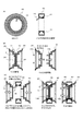
図1は、実施例1にかかるタイヤホイールのホイールの基本構成を模式的に示した図である。図2は図1に示したタイヤホイールにおける内タイヤの取り付け方法を示す図である。なお、装着手順などは一例であり、ビード部への取り付けなど細かい手順については図示を省略している。 FIG. 1 is a diagram schematically illustrating a basic configuration of a wheel of a tire wheel according to a first embodiment. FIG. 2 is a view showing a method of attaching the inner tire in the tire wheel shown in FIG. Note that the mounting procedure is an example, and the detailed procedure such as attachment to the bead portion is not shown.
図1は本発明の二重構造を備えたタイヤホイールのホイール10の概観を示しており、図1(A)が正面図、図1(B)が側面図、図1(C)が第2のリムバルブがない部分における縦断面図、図1(D)が第2のリムバルブがある部分における縦断面図となっている。図1(E)はホイール10の展開図である。図2(A)は本発明の収納空間の一例を示し、図2(B)は従来のホイールの外形を示し、本発明におけるホイールの収納空間を分かりやすく比較した図である。通常のホイールが備えるその他の構造物などの図示は省略している。
なお、この図では正面側がタイヤホイールの外輪側であり、側面図において左側が外輪側、右側が内輪側となっている。つまり、図1(E)において左右2分割されたホイールのうち左側が外輪ホイール体20、右側が内輪ホイール体30となっている。
FIG. 1 shows an overview of a
In this figure, the front side is the outer ring side of the tire wheel, and the left side is the outer ring side and the right side is the inner ring side in the side view. That is, in FIG. 1 (E), the left and right divided wheels are the
実施例1の構成例では、ホイール体10を外輪ホイール体20と内輪ホイール体30に分割した形であり、外輪ホイール体接合部24および内輪ホイール体接合部34が双方ともに円板であり、その円板同士をホイール締結具13aおよび13bで留めて外輪ホイール体と内輪ホイール体を分割可能に合体するものである。この場合、後述するようにシャフト60は内輪ホイール体接合部34に当接するのでシャフト60をそれら円板とシャフト締結具61で締結する構造となっている。この例ではホイール体を上下方向に支える壁面構造がほぼ中央付近に設けられているタイプのホイールへの適用例である。
In the configuration example of Example 1, the
図1(A)から図1(E)に示すように、本発明におけるホイール10は、外輪ホイール体20、内輪ホイール体30、内タイヤ40の構成を備え、さらに、図2(A)に示すように、外輪ホイール体20と内輪ホイール体30が合体された状態で、リム面に設けられている第1の嵌合形状11、内タイヤ40を収納するための収納空間12が形成され、その他には外輪ホイール体20と内輪ホイール体30とを締結するためのホイール締結具13aおよび13b、第1のリムバルブ14、第2のリムバルブ15などが設けられている。
As shown in FIG. 1 (A) to FIG. 1 (E), the
外輪ホイール体20は、外周縁を形成するフランジ21、後述するシャフト締結具61を取り付けるための孔22、ホイール締結具13を取り付けるための孔23、外輪ホイール体20と内輪ホイール体30が合体する際の境界面を形成する外輪ホイール体接合部24を備えている。
なお、この例ではホイール10に装着されるチューブレスタイヤ50の空気圧を調整する第1のリムバルブ14と、後述する内タイヤ40の空気圧を調整するための第2のリムバルブ15が、外輪ホイール体20側に設けられている。
The outer
In this example, the
内輪ホイール体30は、外周縁を形成するフランジ31、後述するシャフト締結具61を取り付けるための孔32、外輪ホイール体20と内輪ホイール体30が合体する際の境界面を形成する内輪ホイール体接合部34を備えている。なお、この構成例ではホイール締結具13bが内輪ホイール体30から突出する形で設けられており、いわゆるボルトとなっている。後述するようにナットに該当するホイール締結具13aとで締結する。
外輪ホイール体接合部24と内輪ホイール体接合部34とは円板状の壁面となっており、両者を合わせることにより合体し、ホイール締結具13aおよび13bで締結することにより両者を固定する。
The inner
The outer ring wheel body
なお、外輪ホイール体接合部24と内輪ホイール体接合部34との接合力を強くするため、両者の境界面に凹凸を付けて噛み合わせたり、一方にツメなどの突起形状を設けて他方には突起体と嵌合する受容形状を設けて両者を嵌合させたりなど、外輪ホイール体接合部24と内輪ホイール体接合部34との接合力を大きくする事が可能である。
In order to strengthen the joining force between the outer ring wheel body
図2(A)は、外輪ホイール体20と内輪ホイール体30が合体された状態で内タイヤ40を図示せずに示した図である。図2(B)は比較するため従来型のホイール体を示した図である。
図2(A)に示すように、第1の嵌合形状11は、ホイール10のリム面に設けられた形状であり、この例では図1(A)に示すような断面形状となっている。この例では溝と突起があり、いわゆる返しのようになっており、後述するように内タイヤの第2の嵌合形状41がこの第1の嵌合形状11に嵌り込んだ後は容易には抜け出ないものとなっている。なお、第1の嵌合形状11の断面形状は図1(A)に示したものには限定されない。
FIG. 2A is a view showing the
As shown in FIG. 2 (A), the first
収納空間12は、従来のウエルの内径を落とし込む(削る)ことにより構成され、内タイヤ40の収納空間として提供される。ウエルの内径を落とし込んでいるために、図2(B)に示したような従来のホイールのリムに比べて、収納空間を広く確保することができる。収納空間12の範囲はハッチングを付けて表している。収納空間12の中には内タイヤ40が収納されている。
The
ホイール締結具13は、外輪ホイール体20と内輪ホイール体30の合体の際に外輪ホイール体接合部24と内輪ホイール体接合部34を締結するための締結具である。この例では、いわゆるボルト・ナットで締結するものとなっており、内輪ホイール体接合部34にはボルトに該当するホイール締結具13bが設けられており、外輪ホイール体接合部24にはホイール締結具13bが通る孔23が設けられており、外輪ホイール体接合部24の外輪側からナットに該当するホイール締結具13aにより締結するものとなっている。
なお、この例では、3か所のホイール締結具13を設けたが、数は限定されない。
The
In this example, three
第1のリムバルブ14および第2のリムバルブ15は、構造的には通常のリムバルブと同様のもので良くその詳しい図示は省略しているが、第1のリムバルブ14の空気挿入口はチューブレスタイヤ50の内部で空気圧を調整できる位置に導かれており、第2のリムバルブ15の空気挿入口は後述する内タイヤ40の内部の空気圧を調整できる位置に導かれている。
The
図3(A)および図4(A)は内タイヤ40を取り出して示した図である。図3(A)は第2のリムバルブ15が無い部分の縦断面図であり、図4(A)は第2のリムバルブ15がある部分の縦断面図を示している。
FIG. 3A and FIG. 4A are views showing the
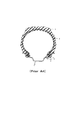
内タイヤ40は多少の弾力性があり構造強度を備えた素材で作られており、輪状の袋構造を持ち、空気などの気体を充填することにより膨らむ。素材としてはたとえば、薄手の強化ゴム、強化プラスチック、強化繊維などがあり、さらに構造的強度を向上させるためにグラスファイバー、チタンなどを配合しても良い。
The
内タイヤ40は収縮した状態では収納空間12の中に収められるサイズに製作されており、第2のリムバルブ15により空気などを充填することにより膨らみ、内タイヤ40がホイール10の中子となる。
内タイヤ40には図3(a)に示すように、第2の嵌合形状41が設けられている。この例では底部付近に設けられている。例えば、第2の嵌合形状41は、厚手で強固なゴム素材により構成され、第1の嵌合形状11と嵌合させて噛み合わせることにより固定して遠心力によっても外れなくなるように工夫されている。この方法で内タイヤ40を収縮した状態にてホイール10の収納空間12の底部に固定しておく。
The
As shown in FIG. 3A, the
図3(B)および図3(C)、図4(B)および図4(C)は、内タイヤ40を取り付ける方法を示した図である。図3(B)および図3(C)は第2のリムバルブ15が無い部分の縦断面図において内タイヤ40の固定方法を示したものであり、図4(B)および図4(C)は第2のリムバルブ15がある部分の縦断面図において内タイヤ40の固定方法を示したものである。
3 (B), 3 (C), 4 (B), and 4 (C) are diagrams showing a method of attaching the
まず、図3(B)および図4(B)に示すように、ホイール体10を分割し、外輪ホイール体20と内輪ホイール体30に分割する。
First, as shown in FIGS. 3B and 4B, the
次に、図3(C)および図4(C)に示すように、外輪ホイール体20と内輪ホイール体30を合わせつつ、リム面に形成される第1の嵌合形状11に対して内タイヤ40の第2の嵌合形状41を挟み込んで嵌合させつつ両者を合体する。
なお、内タイヤ40において第2のリムバルブ15が設けられている部分の嵌合は、外輪ホイール体20または内輪ホイール体30のいずれかの壁面を通して口を外部に出す必要がある。この例では図4(C)に示すように外輪ホイール体20側に、第2のリムバルブ15が通る孔が開いており(図示せず)、この孔に第2のリムバルブ15を通し、図4(C)に示すように第2のリムバルブ15を外面に出した状態で内タイヤ40を挟み込みつつ外輪ホイール体20と内輪ホイール体30を嵌合する。
Next, as shown in FIG. 3 (C) and FIG. 4 (C), the inner tire with respect to the first
In addition, in the fitting of the portion where the
次に、外輪ホイール体接合部24と内輪ホイール体接合部34を合わせた後、両者の固定を確実にするため、図3(C)および図4(C)に示すように、ホイール締結具13a,13bにより締結する。
Next, after the outer ring wheel body
次に、ホイール体10にチューブレスタイヤ50を取り付け、内タイヤ40を膨らませる方法について説明する。
なお、以下、内タイヤ40に充填する空気の空気圧やチューブレスタイヤ50に充填する空気の空気圧についての説明は一例であり、本発明の技術的範囲を限定するものではない。
Next, a method for attaching the
Hereinafter, the description of the air pressure filled in the
図5は、ホイール体10にチューブレスタイヤ50を取り付け、内タイヤ40を膨らませる手順を示す図である。
図5ではチューブレスタイヤ50について、その外形概略は実線で示され、内部の断面概略形状は点線で示されている。内部の断面概略形状はホイール10の装着関係の概略を分かりやすくするために併せて示している。
FIG. 5 is a diagram showing a procedure for attaching the
In FIG. 5, the outline of the
まず、図5(A)左側に示すように、チューブレスタイヤ50に対してホイール体10を通し入れる。チューブレスタイヤ50のビード部(図示せず)をホイール体10のビードシート(図示せず)に対して従来の方法にて取り付ける(詳細は図示せず)。チューブレスタイヤ50のビード部およびホイール10のビードシートの形状や構造は従来と同じで良い。
この時、内タイヤ40は収縮して収納空間12の中に収納されている状態であり、その径が小さくなっているので、内タイヤ40の高さは内輪ホイール体30のフランジ31、外輪ホイール体20のフランジ21の高さよりも低くなっている。この状態であれば、図5(A)右図に示すように従来の通常の手順に従って装着が可能となる。
First, as shown in the left side of FIG. 5A, the
At this time, the
チューブレスタイヤ50をホイール体10へ通し入れることにより、図5(A)右図に示すようにビード部を介してチューブレスタイヤ50とホイール体10が密に嵌合されチューブレスタイヤ50の内部が密閉される。ただし、まだこの段階では、第1のリムバルブ14は開放されておりチューブレスタイヤ50の内側は外気と通じており空気圧は外気圧と同じである。
By passing the
次に、図5(B)左図から右図に示すように、内タイヤ40を膨らませ、チューブレスタイヤ50の内部において展開する(第1の手順)。
この内タイヤ40の膨張については第2のリムバルブ15を介して行なう。第2のリムバルブ15は外気と内タイヤ40の内部とを通じさせるものであり、空気の流通とバルブの開閉を制御することにより内タイヤ40の内部の空気圧を調整することができる仕組みとなっている。この第2のリムバルブ15を介して内タイヤ40の内部の空気圧を増加し、内タイヤ40を膨らませてチューブレスタイヤ50の内部で展開させる。内タイヤ40を膨らませた後は第2のリムバルブ15を閉じて内タイヤ40を密閉し、内タイヤ40の膨張状態を維持固定する。内タイヤ40は膨らんだ状態においては、その径はフランジ11の径より大きいものとなっており、二重構造を備えたタイヤの中子として機能しうるサイズとなっている。
なお、この段階では、チューブレスタイヤ50の内部の空気圧は第1のリムバルブ14を開いているので外気圧と同じである。
Next, as shown in FIG. 5B from the left to the right, the
The expansion of the
At this stage, the air pressure inside the
次に、チューブレスタイヤ50の空気圧を調整する。第1のリムバルブ14を介してチューブレスタイヤ50の内部の空気圧を調整し、その後第1のリムバルブ14を閉じ、チューブレスタイヤ50を密封する(第2の手順)。
チューブレスタイヤ50の内圧を所定の空気圧となるまで空気を充填するとチューブレスタイヤ50が通常の使用状態にまで膨らみ、車両の走行に適したものとなる。
Next, the air pressure of the
If the
なお、上記の2つの手順、つまり、第1の手順として最初に第2のリムバルブ15で内タイヤ40の内圧を所定圧力まで調整し、その後、第2の手順により第1のリムバルブ14でチューブレスタイヤ50の内圧を所定圧力まで調整する。この2段階の手順によれば、内タイヤ40に充填する空気量を、パンク時に内タイヤ40が中子としての膨らみを維持するための適切な量とすることができる。
Note that, as the first procedure, the inner pressure of the
その理由は以下の通りである。外側のチューブレスタイヤ50がパンクした場合、チューブレスタイヤ50内の空気圧が所定圧力から急激に外気圧まで下がるところ、内タイヤ40が自らの内圧による膨張に耐えなければ内タイヤ40も一緒に破裂してしまう。上記手順であれば最初に第2のリムバルブ15で内タイヤ40の内圧を所定圧力まで調整する際はチューブレスタイヤ50は外気圧となっており、内タイヤ40に充填された空気量は外気圧に対して適度に膨らむための適切な量となるからである。
The reason is as follows. When the
なお、第2の手順により第1のリムバルブ14を介してチューブレスタイヤ50を所定圧力まで高めてゆくと、内タイヤ40も押圧されて当該所定圧力まで高められ、内タイヤ40自体はやや萎む。しかし、このようにやや萎んだ状態であることにより、パンク時にチューブレスタイヤ50の内圧が急激に外気圧まで下がった場合には自らの内圧でしっかりと膨らみ、中子の役割を果たすことができる。
When the
次に、本発明のタイヤホイール100のシャフトへの取り付け方法を説明する。
現在、一般に、タイヤホイールとシャフトとの取り付け方法には、少なくとも2種類あり、シャフトからボルトが出ており、タイヤホイール外輪側からナットで締結するタイプ1と、シャフトには孔が開いており、タイヤホイール外輪側からボルトを打ち込んで、シャフト内部からナットで締結するタイプ2がある。
Next, a method for attaching the
Currently, there are generally at least two types of methods for attaching the tire wheel and the shaft, the bolt comes out of the shaft, the type 1 that is fastened with a nut from the outer side of the tire wheel, and the shaft has a hole, There is a
まず、タイプ1の場合の取り付け手順について説明する。
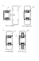
図6および図7は、上記のタイプ1の場合における、タイヤホイール100のシャフト60への取り付け手順を示した図である。
図6(A)から図6(B)に示すように、シャフト60から突出しているボルト61bに対して、タイヤホイール100を取り付ける。内輪ホイール体30には孔32があり、外輪ホイール体20には孔22があり、ボルト61が孔32および孔22を貫く。
First, the attachment procedure in the case of type 1 will be described.
FIGS. 6 and 7 are diagrams showing a procedure for attaching the
As shown in FIGS. 6A to 6B, the
次に、図7(A)から図7(B)に示すように外輪ホイール体20の外面側からナット61aをボルト61bに取り付けて締結する。なお、数は限定されないが、例えば5つか6つ程度の締結箇所としても良い。
図7(B)右図は、上記手順により空気を充填して得た、二重構造を備えたタイヤホイール100の完成状態の一例を示した図である。
Next, as shown in FIGS. 7A to 7B, a
The right figure of FIG.7 (B) is the figure which showed an example of the completion state of the
次に、タイプ2の場合の取り付け手順について説明する。
図8および図9は、上記のタイプ2の場合における、タイヤホイール100のシャフト60への取り付け手順を示した図である。
Next, the attachment procedure in the case of
FIGS. 8 and 9 are diagrams showing a procedure for attaching the
まず、図8(A)から図8(B)に示すように、シャフト60に対してタイヤホイール100をあてがう。この状態でシャフト先端に設けられている孔(図示せず)の位置と、外輪ホイール体20の孔22と内輪ホイール体30の孔32の位置が対応するように調整する。
First, as shown in FIGS. 8A to 8B, the
次に、図9(A)から図9(B)に示すように、外輪ホイール体20の外輪側からボルト61bを打ちこむ。シャフト内部においてナット61aで受けて締結することによりシャフト60とタイヤホイール100をしっかりと固定する。
図9(B)右図は、上記手順により空気を充填して得た、二重構造を備えたタイヤホイール100の完成状態の一例を示した図である。
Next, as shown in FIGS. 9A to 9B, the
The right figure of FIG.9 (B) is the figure which showed an example of the completion state of the
次に、外側のチューブレスタイヤ50がパンクした場合の効果について説明する。
図10の左側が正常な状態を示す図、中央は本発明のチューブレスタイヤ50がパンクした状態を示す図、右側は従来のチューブレスタイヤ50がパンクした状態を示す図である。
チューブレスタイヤ50がパンクした場合、チューブレスタイヤ50が破れて車重を支えられなくなり車体が落ち込むが、車体の落ち込みが大きいほどハンドル操作が困難となり危険性が増す。従来のタイヤホイールでは図10左図のパンク前の状態から図10右図の従来のパンク後の状態まで一気に車体が落ち込むこととなる。つまり、高さB分落ち込むこととなり非常に危険な状態を招く。一方、本発明の場合、内タイヤ40により一時的に車重を支える構造となっているので、図10左図のパンク前状態から図10中央図の本発明のタイヤホイール100を採用した場合のパンク後の状態まで車体が落ち込むこととなる。つまり、高さA分落ち込むこととなる。車体が落ち込む高さを比較すると明らかなように、従来のタイヤホイールでは高さB分落ち込むのに対して本発明のタイヤホイール100では高さA分のみしか落ち込まないので、パンク時であっても落ち込みが小さく、より安全なものとなる。
Next, the effect when the
The left side of FIG. 10 shows a normal state, the center shows a state in which the
When the
なお、パンク時において、中子となる内タイヤ40の構造的強度に関して説明しておく。外側のチューブレスタイヤ50はパンクしても完全には破り取れず一時的にホイールの周囲に残存する。このとき内タイヤ40は外側のチューブレスタイヤ50に対する一種のチューブのような働きをする。つまり一時的ではあるがチューブタイヤのように働くこととなる。長時間走行ではなく停止するまでの短時間走行であれば外側のチューブレスタイヤ50と内タイヤ40によりチューブタイヤの如くの走行が可能となる。本発明は当該効果を狙っている。
It should be noted that the structural strength of the
次に、タイヤ交換の手順について説明しておく。本発明の特徴として、外側のチューブレスタイヤ50が磨耗して交換が必要となった場合などにおいて、外側のチューブレスタイヤ50のみを交換できることもできる。従来のランフラットタイヤであれば外側のチューブレスタイヤ50が磨耗した場合でもランフラットタイヤ全体を交換する必要があった。本発明では外側のチューブレスタイヤ50と内タイヤ40は分離されているので外側のチューブレスタイヤ50のみを交換すればよい。
取り外しの第1の手順は、上記の図6から図7の手順、または、図8から図9の手順の逆の手順で取り外せば良い。
Next, the procedure for tire replacement will be described. As a feature of the present invention, it is possible to replace only the
The first removal procedure may be removed by the procedure shown in FIGS. 6 to 7 or the reverse procedure of the procedure shown in FIGS.
以上、本発明の実施例1にかかる二重構造を備えたタイヤホイールの構成例を示したが、上記構成は一例であり種々の変更が可能である。 As mentioned above, although the structural example of the tire wheel provided with the double structure concerning Example 1 of this invention was shown, the said structure is an example and a various change is possible.
実施例2の二重構造を備えたタイヤホイールとして、ホイールが外輪ホイール体と内輪ホイール体に分割でき、分割状態の外輪ホイール体と内輪ホイール体を合体させつつ内タイヤを嵌合させて固定せしめる構造のうち、車両本体のシャフトに対してタイヤホイールを装着すると、シャフトが内輪ホイール体接合部に当接し、内輪ホイール体接合部とシャフトの2者がシャフト締結具により締結される構造例を示す。 As the tire wheel having the double structure of the second embodiment, the wheel can be divided into an outer ring wheel body and an inner ring wheel body, and the inner tire is fitted and fixed while combining the divided outer ring wheel body and inner ring wheel body. In the structure, when the tire wheel is attached to the shaft of the vehicle main body, the shaft contacts the inner ring wheel body joint, and the inner ring wheel body joint and the shaft are fastened by the shaft fastener. .
この実施例2の例は、実施例1のバリエーションである。実施例1の構成例では、外輪ホイール体接合部24と内輪ホイール体接合部34が円板状の壁面であり、シャフト60は内輪ホイール体接合部34に当接し、ホイール締結具61a,61bにより外輪ホイール体接合部24と内輪ホイール体接合部34とシャフト60の3者が締結されるが、この実施例2では外輪ホイール体接合部24の中央に孔25が開いており、ホイール締結具61a,61bにより内輪ホイール体接合部34とシャフト60の2者が締結されるものとなっている。
The example of the second embodiment is a variation of the first embodiment. In the configuration example of the first embodiment, the outer ring wheel body
図11は、実施例2のタイヤホイールの構造を縦断面において示した図である。シャフトへの取り付けは実施例1のタイプ1のものとして説明している。図11(A)に示すように、外輪ホイール接合部24は中央に孔25が設けられている。図11(A)左図から右図に示すように、シャフト60に対してタイヤホイール100aをシャフト60に取り付けると、実施例1の図6(A)や図8(A)と同様にシャフト60の先端は内輪ホイール体接合部34に当接する。
FIG. 11 is a view showing the structure of the tire wheel of Example 2 in a longitudinal section. The attachment to the shaft is described as the type 1 of the first embodiment. As shown in FIG. 11A, the outer ring wheel joint 24 is provided with a
次に、図11(B)左図から右図に示すように、シャフト60の先端から突出しているホイール締結具61bに対して、外輪ホイール体20の外輪側からナットであるホイール締結具61aを取り付ける。つまり、図11(B)に示すように、ホイール締結具61により締結されるのは、内輪ホイール体接合部34とシャフト60の2者である。
Next, as shown in FIG. 11B from the left to the right, the
以上、本発明の実施例2にかかる二重構造を備えたタイヤホイールの構成例を示したが、上記構成は一例であり種々の変更が可能である。 As mentioned above, although the structural example of the tire wheel provided with the double structure concerning Example 2 of this invention was shown, the said structure is an example and a various change is possible.
実施例3の二重構造を備えたタイヤホイールとして、ホイールが外輪ホイール体と内輪ホイール体に分割でき、分割状態の外輪ホイール体と内輪ホイール体を合体させつつ内タイヤを嵌合させて固定せしめる構造のうち、車両本体のシャフトに対してタイヤホイールを装着すると、シャフトが内輪ホイール体接合部を通過して外輪ホイール体接合部に当接し、外輪ホイール体接合部とシャフトの2者がシャフト締結具により締結される構造例を示す。 As a tire wheel having the double structure of the third embodiment, the wheel can be divided into an outer ring wheel body and an inner ring wheel body, and the inner tire is fitted and fixed while combining the divided outer ring wheel body and inner ring wheel body. Of the structure, when the tire wheel is mounted on the shaft of the vehicle body, the shaft passes through the inner ring wheel body joint and contacts the outer wheel body joint, and the outer wheel body joint and the shaft are fastened by the shaft. The structural example fastened with a tool is shown.
この実施例3の例は、実施例1のバリエーションである。実施例1の構成例では、外輪ホイール体接合部24と内輪ホイール体接合部34が円板状の壁面であり、シャフト60は内輪ホイール体接合部34に当接し、ホイール締結具61a,61bにより外輪ホイール体接合部24と内輪ホイール体接合部34とシャフト60の3者が締結されるが、この実施例3では内輪ホイール体接合部34の中央に孔35が開いており、ホイール締結具61a,61bにより外輪ホイール体接合部24とシャフト60の2者が締結されるものとなっている。
The example of the third embodiment is a variation of the first embodiment. In the configuration example of the first embodiment, the outer ring wheel body
図12は、実施例3のタイヤホイールの構造を縦断面において示した図である。シャフトへの取り付けは実施例1のタイプ1のものとして説明している。図12(A)に示すように、内輪ホイール接合部34は中央に孔35が設けられている。図12(A)左図から右図に示すように、シャフト60に対してタイヤホイール100bをシャフト60に取り付けると、シャフト60の先端は内輪ホイール体30の孔35を通過し、外輪ホイール体接合部24に当接することとなる。
FIG. 12 is a view showing the structure of the tire wheel of Example 3 in a longitudinal section. The attachment to the shaft is described as the type 1 of the first embodiment. As shown in FIG. 12A, the inner ring wheel joint 34 is provided with a
次に、図12(B)左図から右図に示すように、シャフト60の先端から突出しているホイール締結具61bに対して、外輪ホイール体20の外輪側からナットであるホイール締結具61aを取り付ける。つまり、図12(B)に示すように、ホイール締結具61により締結されるのは、外輪ホイール体接合部24とシャフト60の2者である。
Next, as shown in FIG. 12 (B) from the left to the right, the
以上、本発明の実施例3にかかる二重構造を備えたタイヤホイールの構成例を示したが、上記構成は一例であり種々の変更が可能である。 As mentioned above, although the structural example of the tire wheel provided with the double structure concerning Example 3 of this invention was shown, the said structure is an example and a various change is possible.
実施例4の二重構造を備えたタイヤホイールとして、ホイールが外輪ホイール体と内輪ホイール体に分割でき、分割状態の外輪ホイール体と内輪ホイール体を合体させつつ内タイヤを嵌合させて固定せしめる構造のうち、ホイール体を上下方向に支える構造が外輪側に設けられているタイプのホイールへの適用例であり、シャフトが内輪リム体接合部および外輪リム体接合部を通過し、外輪リム体の外側面部の内側に当接し、外輪リム体の外側面部とシャフトの2者がシャフト締結具により締結される構造例である。 As a tire wheel having the double structure of the fourth embodiment, the wheel can be divided into an outer ring wheel body and an inner ring wheel body, and the inner tire is fitted and fixed while combining the divided outer ring wheel body and inner ring wheel body. Among the structures, this is an example of application to a type of wheel in which the structure that supports the wheel body in the vertical direction is provided on the outer ring side, and the shaft passes through the inner ring rim body joint and the outer ring rim body joint, and the outer ring rim body This is an example of a structure in which the outer surface portion of the outer ring rim body and the shaft are fastened together by a shaft fastener.
図13は、実施例4にかかるタイヤホイール100aのホイール10aの基本構成を模式的に示した図であり、図13(A)が正面図、図13(B)が側面図、図13(C)が第2のリムバルブがない部分における縦断面図、図13(D)が第2のリムバルブがある部分における縦断面図となっている。図13(E)はホイール10aの展開図である。通常のホイールが備えるその他の構造物などの図示は省略している。
なお、この図では正面側がタイヤホイールの外輪側であり、側面図において左側が外輪側、右側が内輪側となっている。つまり、図13(E)において左右2分割されたホイールのうち左側が外輪ホイール体20a、右側が内輪ホイール体30aとなっている。
各構成要素において、実施例1と同様の部分の説明は省略する。
FIG. 13 is a diagram schematically illustrating the basic configuration of the
In this figure, the front side is the outer ring side of the tire wheel, and the left side is the outer ring side and the right side is the inner ring side in the side view. That is, in FIG. 13E, the left wheel is the
In each component, the description of the same part as in the first embodiment is omitted.
図13(A)から図13(E)に示すように、本発明におけるホイール10aは、外輪ホイール体20a、内輪ホイール体30a、内タイヤ40の構成を備えており、さらに、外輪ホイール体20aと内輪ホイール体30aが合体された状態で、リム面に設けられている第1の嵌合形状11、内タイヤ40を収納するための収納空間12が形成され、その他には外輪ホイール体20と内輪ホイール体30とを締結するためのホイール締結具13aおよび13b、第1のリムバルブ14、第2のリムバルブ15などが設けられている。なお、第1の嵌合形状11、収納空間12、第1のリムバルブ14、第2のリムバルブ15は実施例1の構成と同様である。
As shown in FIG. 13 (A) to FIG. 13 (E), the
実施例4の構成例では、図13(C)に示すように、ホイール体10aを上下方向に支える壁面26が外輪ホイール体20aの外輪側端部に設けられている。
In the configuration example of the fourth embodiment, as shown in FIG. 13C, a
外輪ホイール体20aは、フランジ21、孔22は実施例1と同様であるが、ホイール締結具13a、13bは外輪ホイールの外輪側の面にはないので、ホイール締結具13a,13bを受け入れるための孔23はない。また、実施例1では外輪ホイール体接合部24が外輪ホイールの外輪側の面に設けられていたが、実施例4では、外輪ホイール体接合部24が図13(E)に示すように内輪ホイールに対向する側に設けられている。また、外輪ホイール体接合部24には実施例2と同様、中央部分に孔25が設けられており、シャフトがこの孔25を通過する構成となっている。また、ボルトに相当するホイール締結具13bが実施例1とは異なり、外輪ホイール体接合部24側に設けられている。
The outer
内輪ホイール体30aは、フランジ31、孔32は実施例1と同様であるが、孔32は、外輪ホイール体20に設けられたホイール締結具13bに対応する位置に設けられている。内輪ホイール体接合部34は、例えば、図13(C)に示すようなものであり、外輪ホイール体接合部24に対向するものとなっている。なお、実施例3と同様、内輪ホイール体接合部34にはシャフト60が通過する孔35が設けられている。
The inner
外輪ホイール体接合部24と内輪ホイール体接合部34とは中央に大きな孔25、35が開いている円板状の壁面となっており、両者を合わせることにより合体し、ホイール締結具13aおよび13bで締結することにより両者を固定する。
なお、外輪ホイール体接合部24と内輪ホイール体接合部34との接合力を強くするため、両者の境界面に凹凸を付けて噛み合わせたり、一方にツメなどの突起形状を設けて他方には突起体と嵌合する受容形状を設けて両者を嵌合させたりなど、外輪ホイール体接合部24と内輪ホイール体接合部34との接合力を大きくする工夫は可能である。
The outer ring wheel body
In order to strengthen the joining force between the outer ring wheel body
次に、内タイヤ40と内タイヤ40の取り付け方法について説明する。
図14および図15は、内タイヤ40の構造と内タイヤ40の取り付け方法を説明した図である。
Next, an
14 and 15 are diagrams illustrating the structure of the
まず、内タイヤ40の構造自体は実施例1に示したものと同様である。
内タイヤ40の取り付け方法も実施例1と同様であるが、実施例4のホイール体10aの構造が実施例1のホイール体10とは異なるため、念のため図示したものである。
図14(B)および図14(C)は第2のリムバルブ15が無い部分の縦断面図において内タイヤ40の固定方法を示したものであり、図15(B)および図15(C)は第2のリムバルブ15がある部分の縦断面図において内タイヤ40の固定方法を示したものである。基本的には実施例1に示した手順と同じである。
First, the structure of the
The mounting method of the
14 (B) and 14 (C) show the fixing method of the
まず、図14(B)および図15(B)に示すように、ホイール体10aを外輪ホイール体20aと内輪ホイール体30aに分割する。
First, as shown in FIGS. 14B and 15B, the
次に、図14(C)および図15(C)に示すように、外輪ホイール体20aと内輪ホイール体30aを合わせつつ、リム面に形成される第1の嵌合形状11に対して内タイヤ40の第2の嵌合形状41を挟み込んで嵌合させつつ両者を合体する。
なお、内タイヤ40において第2のリムバルブ15が設けられている部分の嵌合は、外輪ホイール体20aまたは内輪ホイール体30aのいずれかの壁面を通して口を外部に出す。この例では図15(C)に示すように外輪ホイール体20a側に、第2のリムバルブ15が通る孔があり(図示せず)、この孔に第2のリムバルブ15を通し、図15(C)に示すように第2のリムバルブ15を外面に出した状態で内タイヤ40を挟み込みつつ外輪ホイール体20aと内輪ホイール体30aを嵌合する。
Next, as shown in FIG. 14 (C) and FIG. 15 (C), the inner tire with respect to the first
In addition, in the fitting of the portion where the
次に、外輪ホイール体接合部24と内輪ホイール体接合部34を合わせた後、両者の固定を確実にするため、図14(C)および図15(C)に示すように、内輪ホイール体30aの内輪側に突出したホイール締結具13に対してホイール締結具13aを締めて締結する。
図14(C)および図15(C)の右図はホイール締結具13aにより締結した後の内輪ホイール体30aを内輪側から見た図である。中央にシャフト60を入れる孔35が大きく開けられており、向こう側に外輪ホイール体20aの外輪端面の壁面26が見える(図示せず)。
Next, after the outer ring wheel body
14C and 15C are views of the inner
次に、実施例4のホイール体10aにチューブレスタイヤ50を取り付け、内タイヤ40を膨らませる手順については実施例1と同様である。
図16は、ホイール体10aにチューブレスタイヤ50を取り付け、内タイヤ40を膨らませる手順を示す図である。
Next, the procedure for attaching the
FIG. 16 is a diagram showing a procedure for attaching the
まず、図16(A)左側に示すように、チューブレスタイヤ50に対してホイール体10aを通し入れる。この時、内タイヤ40は収縮して収納空間12の中に収納されている状態であり、その径が小さくなっているので、内タイヤ40の高さは内輪ホイール体30aのフランジ31、外輪ホイール体20aのフランジ21の高さよりも低くなっている。この状態であれば、図16(A)右図に示すように従来の通常の手順に従って装着が可能となる。
その後、内タイヤ40に対して第2のリムバルブ15からエアーを充填する手順、チューブレスタイヤ50に対して第1のリムバルブ14からエアーを充填する手順は実施例と同様である。
First, as shown on the left side of FIG. 16A, the
Thereafter, the procedure for filling the
次に、実施例4のタイヤホイール100aのシャフト60への取り付け方法を説明する。
ここでは、実施例1に示した、シャフトからボルトが出ておりタイヤホイール外輪側からナットで締結するタイプ1のものを例に説明する。
図17および図18は、上記のタイプ1の場合における、タイヤホイール100aのシャフト60への取り付け手順を示した図である。
Next, the attachment method to the
Here, the description will be made by taking as an example the type 1 shown in the first embodiment, in which a bolt protrudes from the shaft and is fastened with a nut from the outer side of the tire wheel.
FIGS. 17 and 18 are diagrams showing a procedure for attaching the
図17(A)から図17(B)に示すように、シャフト60から突出しているボルト61bに対して、タイヤホイール100aを取り付ける。内輪ホイール体30aには孔35があり、外輪ホイール体20には孔25があり、シャフト60はそれらを通過し、外輪ホイール体20の外輪端面にある壁面26の裏面まで到達して当接する。
As shown in FIGS. 17A to 17B, the
シャフト60の先端にはボルトに相当するシャフト締結具61bがあり、外輪ホイール体20の外輪端面にある壁面26には孔32があり、ボルトに相当するシャフト締結具61bの先端は壁面26から突出する。
A
次に、図18(A)から図18(B)に示すように、外輪ホイール体20の壁面26の外面側からナットに相当するシャフト締結具61aをシャフト締結具61bに取り付けて締結する。なお、数は特に限定されないが、例えば、5つや6つ程度の締結箇所としても良い。
図18(B)右図は、上記手順により空気を充填して得た、二重構造を備えたタイヤホイール100aの完成状態の一例を示した図である。
Next, as shown in FIGS. 18 (A) to 18 (B), a
The right figure of FIG.18 (B) is the figure which showed an example of the completion state of the
以上、本発明の実施例4にかかる二重構造を備えたタイヤホイールの構成例を示したが、上記構成は一例であり種々の変更が可能である。 As mentioned above, although the structural example of the tire wheel provided with the double structure concerning Example 4 of this invention was shown, the said structure is an example and a various change is possible.
実施例5として、本発明の二重構造を備えたタイヤホイール100、100a,100cなどを適用した車両の例を挙げておく。
図19(A)は、乗用車に適用した例である。図19(A)に図示したタイプの車両に限定されず、多種多様な車両のタイヤに適用することができる。図19(B)は、バイクなどの自動二輪車に適用した例である。図19(B)に図示したタイプの自動二輪車に限定されず、多種多様な自動二輪車のタイヤに適用することができる。図20(A)は飛行機に適用した例である。図20(B)は衛星探査機に適用した例である。なお、図示しないがその他の重機などの特殊車両であっても、タイヤを装着している機器であれば、本発明の二重構造を備えたタイヤホイール100、100a,100cなどを適用することは可能である。
As Example 5, an example of a vehicle to which the
FIG. 19A shows an example applied to a passenger car. The present invention is not limited to the type of vehicle shown in FIG. 19A, and can be applied to tires of a wide variety of vehicles. FIG. 19B shows an example applied to a motorcycle such as a motorcycle. The present invention is not limited to the type of motorcycle shown in FIG. 19B, and can be applied to various types of motorcycle tires. FIG. 20A shows an example applied to an airplane. FIG. 20B shows an example applied to a satellite probe. Although not shown in the drawings, even if the vehicle is a special vehicle such as another heavy machine, it is possible to apply the
以上、本発明の実施例7にかかる二重構造を備えたタイヤホイールの構成例を示したが、上記構成は一例であり種々の変更が可能である。 As mentioned above, although the structural example of the tire wheel provided with the double structure concerning Example 7 of this invention was shown, the said structure is an example and a various change is possible.
以上、二重構造を備えたタイヤホイールの構成例における好ましい実施例を図示して説明してきたが、本発明の技術的範囲を逸脱することなく種々の変更が可能であることは理解されるであろう。
以上、本発明の好ましい実施形態を図示して説明してきたが、本発明の技術的範囲を逸脱することなく種々の変更が可能であることは理解されるであろう。従って本発明の技術的範囲は添付された特許請求の範囲の記載によってのみ限定されるものである。
As mentioned above, although the preferable example in the structural example of the tire wheel provided with the double structure has been illustrated and described, it is understood that various modifications can be made without departing from the technical scope of the present invention. I will.
While the preferred embodiment of the invention has been illustrated and described, it will be appreciated that various changes can be made without departing from the scope of the invention. Therefore, the technical scope of the present invention is limited only by the description of the appended claims.
本発明の二重構造を備えたタイヤホイールは、例えば、乗用車、トラック、バス等の自動車のタイヤや、バイクなどの自動二輪車、さらには、航空機や特殊車両用のタイヤなどに適用される。The tire wheel having the double structure of the present invention is applied to, for example, automobile tires such as passenger cars, trucks, and buses, motorcycles such as motorcycles, and tires for airplanes and special vehicles.
100 タイヤホイール
10 ホイール
20 外輪ホイール体
30 内輪ホイール体
40 内タイヤ
50 チューブレスタイヤ
60 シャフト
DESCRIPTION OF
Claims (10)
前記ホイールが前記収納空間を外輪側と内輪側に分けるように分割した外輪ホイール体と内輪ホイール体を備え、分割状態の前記外輪ホイール体と前記内輪ホイール体を合体させて前記収納空間が形成される際、前記第1の嵌合形状と前記内タイヤの第2の嵌合形状とを嵌合させて固定せしめたことを特徴とする二重構造を備えたタイヤホイール。A bead seat for attaching a bead portion of a flange and a tubeless tire, a wheel having a storage space that is smaller in diameter than the flange and provided in a well, an inner tire that can be stored in the storage space, and an air pressure of the tubeless tire A second fitting that includes a first rim valve to be adjusted and a second rim valve to adjust the air pressure of the inner tire, wherein a part of the inner tire is fitted to the first fitting shape of the wall surface of the storage space. In the tire wheel having a double structure for fixing the inner tire to the wheel by fitting the first fitting shape and the second fitting shape,
The wheel includes an outer ring wheel body and an inner ring wheel body that are divided so as to divide the storage space into an outer ring side and an inner ring side, and the storage space is formed by combining the outer ring wheel body and the inner ring wheel body in a divided state. In this case, a tire wheel having a double structure, wherein the first fitting shape and the second fitting shape of the inner tire are fitted and fixed.
Applications Claiming Priority (1)
| Application Number | Priority Date | Filing Date | Title |
|---|---|---|---|
| PCT/JP2009/068639 WO2011048708A1 (en) | 2009-10-23 | 2009-10-23 | Tire wheel with double structure and method of mounting same |
Publications (2)
| Publication Number | Publication Date |
|---|---|
| JP4635111B1 true JP4635111B1 (en) | 2011-02-16 |
| JPWO2011048708A1 JPWO2011048708A1 (en) | 2013-03-07 |
Family
ID=43768665
Family Applications (1)
| Application Number | Title | Priority Date | Filing Date |
|---|---|---|---|
| JP2010515307A Expired - Fee Related JP4635111B1 (en) | 2009-10-23 | 2009-10-23 | Tire wheel having double structure and method of attaching the same |
Country Status (2)
| Country | Link |
|---|---|
| JP (1) | JP4635111B1 (en) |
| WO (1) | WO2011048708A1 (en) |
Cited By (1)
| Publication number | Priority date | Publication date | Assignee | Title |
|---|---|---|---|---|
| CN108349302A (en) * | 2015-09-18 | 2018-07-31 | 美观与实用公司 | variable diameter wheel |
Families Citing this family (1)
| Publication number | Priority date | Publication date | Assignee | Title |
|---|---|---|---|---|
| KR102680612B1 (en) * | 2022-08-22 | 2024-07-02 | 넥센타이어 주식회사 | Pneumatic tire wheel for Heavy duty |
Citations (6)
| Publication number | Priority date | Publication date | Assignee | Title |
|---|---|---|---|---|
| JPH0311901U (en) * | 1989-06-23 | 1991-02-06 | ||
| JPH0454831A (en) * | 1990-06-20 | 1992-02-21 | Sanyo Electric Co Ltd | Heater switcher for heating apparatus |
| JPH04102981A (en) * | 1990-08-22 | 1992-04-03 | Sharp Corp | Single chip type microcomputer |
| JPH07300003A (en) * | 1994-04-29 | 1995-11-14 | Isuzu Motors Ltd | Disc wheels for tubeless tires |
| JP2004075039A (en) * | 2002-06-18 | 2004-03-11 | Bridgestone Corp | Safety tire and core for safety tire |
| JP2005170379A (en) * | 2003-12-08 | 2005-06-30 | Hutchinson Sa | Run-flat device for automobile and mounting assembly incorporating the same |
Family Cites Families (2)
| Publication number | Priority date | Publication date | Assignee | Title |
|---|---|---|---|---|
| JP4102981B2 (en) * | 2002-08-04 | 2008-06-18 | 広慶 藤本 | Wheel for puncture |
| JP4054831B1 (en) * | 2006-09-23 | 2008-03-05 | 一博 池田 | Tire wheel with double structure |
-
2009
- 2009-10-23 WO PCT/JP2009/068639 patent/WO2011048708A1/en not_active Ceased
- 2009-10-23 JP JP2010515307A patent/JP4635111B1/en not_active Expired - Fee Related
Patent Citations (6)
| Publication number | Priority date | Publication date | Assignee | Title |
|---|---|---|---|---|
| JPH0311901U (en) * | 1989-06-23 | 1991-02-06 | ||
| JPH0454831A (en) * | 1990-06-20 | 1992-02-21 | Sanyo Electric Co Ltd | Heater switcher for heating apparatus |
| JPH04102981A (en) * | 1990-08-22 | 1992-04-03 | Sharp Corp | Single chip type microcomputer |
| JPH07300003A (en) * | 1994-04-29 | 1995-11-14 | Isuzu Motors Ltd | Disc wheels for tubeless tires |
| JP2004075039A (en) * | 2002-06-18 | 2004-03-11 | Bridgestone Corp | Safety tire and core for safety tire |
| JP2005170379A (en) * | 2003-12-08 | 2005-06-30 | Hutchinson Sa | Run-flat device for automobile and mounting assembly incorporating the same |
Cited By (1)
| Publication number | Priority date | Publication date | Assignee | Title |
|---|---|---|---|---|
| CN108349302A (en) * | 2015-09-18 | 2018-07-31 | 美观与实用公司 | variable diameter wheel |
Also Published As
| Publication number | Publication date |
|---|---|
| JPWO2011048708A1 (en) | 2013-03-07 |
| WO2011048708A1 (en) | 2011-04-28 |
Similar Documents
| Publication | Publication Date | Title |
|---|---|---|
| JPH10250309A (en) | Tubeless tire and rim for bicycle | |
| CN102143848B (en) | Wheel assembly and construction method of wheel assembly | |
| JPH08282208A (en) | Trilocular type tire | |
| CN216184253U (en) | Vehicle and embedded air bag type tire burst continuous running wheel thereof | |
| JP4635111B1 (en) | Tire wheel having double structure and method of attaching the same | |
| US2713372A (en) | Tubeless tire and safety diaphragm combination | |
| US2754876A (en) | Safety tire | |
| CN100513209C (en) | Body acting as a support for a tyre in the event of deflation and tyre set provided with the body | |
| JP4054831B1 (en) | Tire wheel with double structure | |
| CN101678726B (en) | Tire wheel of double structure and method of mounting same | |
| AU2007354898A2 (en) | Pneumatic sealing ring having an inner tube and expandable liner for a tube-type tire | |
| US2811189A (en) | Pneumatic tire | |
| US6892777B2 (en) | Rim with seats inclined outwards and assemblies comprising such a rim and an inflated bearing support | |
| US3060990A (en) | Inflation valve arrangements for pneumatic tires | |
| EP3142871A1 (en) | Foam tire flap for low pressure applications | |
| JP4575607B2 (en) | Run-flat tire and assembly of run-flat tire and rim | |
| US20070000587A1 (en) | Run-flat assembly comprising a foam insert and improved airtight membranes | |
| US6568765B1 (en) | Composite wheel having a shallow rim | |
| US20070017614A1 (en) | Foam insert designed to be incorporated into an assembly for running at reduced pressure | |
| WO2004067298A1 (en) | A wheel with two tires | |
| EP4484142A1 (en) | Pneumatic tire, puncture repair method for pneumatic tire, and vehicle | |
| WO1994026541A1 (en) | Pneumatic safety tire | |
| US4922983A (en) | Vehicle wheel and tire assembly | |
| CN116278516A (en) | A kind of safety tire modified by pneumatic tire | |
| JP6404894B2 (en) | Core type run-flat tire |
Legal Events
| Date | Code | Title | Description |
|---|---|---|---|
| TRDD | Decision of grant or rejection written | ||
| A01 | Written decision to grant a patent or to grant a registration (utility model) |
Free format text: JAPANESE INTERMEDIATE CODE: A01 Effective date: 20101116 |
|
| A01 | Written decision to grant a patent or to grant a registration (utility model) |
Free format text: JAPANESE INTERMEDIATE CODE: A01 |
|
| A61 | First payment of annual fees (during grant procedure) |
Free format text: JAPANESE INTERMEDIATE CODE: A61 Effective date: 20101119 |
|
| R150 | Certificate of patent or registration of utility model |
Ref document number: 4635111 Country of ref document: JP Free format text: JAPANESE INTERMEDIATE CODE: R150 Free format text: JAPANESE INTERMEDIATE CODE: R150 |
|
| FPAY | Renewal fee payment (event date is renewal date of database) |
Free format text: PAYMENT UNTIL: 20131126 Year of fee payment: 3 |
|
| R250 | Receipt of annual fees |
Free format text: JAPANESE INTERMEDIATE CODE: R250 |
|
| R250 | Receipt of annual fees |
Free format text: JAPANESE INTERMEDIATE CODE: R250 |
|
| R250 | Receipt of annual fees |
Free format text: JAPANESE INTERMEDIATE CODE: R250 |
|
| R250 | Receipt of annual fees |
Free format text: JAPANESE INTERMEDIATE CODE: R250 |
|
| R250 | Receipt of annual fees |
Free format text: JAPANESE INTERMEDIATE CODE: R250 |
|
| R250 | Receipt of annual fees |
Free format text: JAPANESE INTERMEDIATE CODE: R250 |
|
| LAPS | Cancellation because of no payment of annual fees |