JP4632905B2 - Geothermal air conditioning system - Google Patents
Geothermal air conditioning system Download PDFInfo
- Publication number
- JP4632905B2 JP4632905B2 JP2005250990A JP2005250990A JP4632905B2 JP 4632905 B2 JP4632905 B2 JP 4632905B2 JP 2005250990 A JP2005250990 A JP 2005250990A JP 2005250990 A JP2005250990 A JP 2005250990A JP 4632905 B2 JP4632905 B2 JP 4632905B2
- Authority
- JP
- Japan
- Prior art keywords
- ground
- air
- underground
- heat
- building
- Prior art date
- Legal status (The legal status is an assumption and is not a legal conclusion. Google has not performed a legal analysis and makes no representation as to the accuracy of the status listed.)
- Expired - Fee Related
Links
Images
Classifications
-
- F—MECHANICAL ENGINEERING; LIGHTING; HEATING; WEAPONS; BLASTING
- F24—HEATING; RANGES; VENTILATING
- F24T—GEOTHERMAL COLLECTORS; GEOTHERMAL SYSTEMS
- F24T10/00—Geothermal collectors
- F24T10/10—Geothermal collectors with circulation of working fluids through underground channels, the working fluids not coming into direct contact with the ground
- F24T10/13—Geothermal collectors with circulation of working fluids through underground channels, the working fluids not coming into direct contact with the ground using tube assemblies suitable for insertion into boreholes in the ground, e.g. geothermal probes
- F24T10/17—Geothermal collectors with circulation of working fluids through underground channels, the working fluids not coming into direct contact with the ground using tube assemblies suitable for insertion into boreholes in the ground, e.g. geothermal probes using tubes closed at one end, i.e. return-type tubes
-
- F—MECHANICAL ENGINEERING; LIGHTING; HEATING; WEAPONS; BLASTING
- F24—HEATING; RANGES; VENTILATING
- F24T—GEOTHERMAL COLLECTORS; GEOTHERMAL SYSTEMS
- F24T10/00—Geothermal collectors
- F24T10/10—Geothermal collectors with circulation of working fluids through underground channels, the working fluids not coming into direct contact with the ground
-
- Y—GENERAL TAGGING OF NEW TECHNOLOGICAL DEVELOPMENTS; GENERAL TAGGING OF CROSS-SECTIONAL TECHNOLOGIES SPANNING OVER SEVERAL SECTIONS OF THE IPC; TECHNICAL SUBJECTS COVERED BY FORMER USPC CROSS-REFERENCE ART COLLECTIONS [XRACs] AND DIGESTS
- Y02—TECHNOLOGIES OR APPLICATIONS FOR MITIGATION OR ADAPTATION AGAINST CLIMATE CHANGE
- Y02B—CLIMATE CHANGE MITIGATION TECHNOLOGIES RELATED TO BUILDINGS, e.g. HOUSING, HOUSE APPLIANCES OR RELATED END-USER APPLICATIONS
- Y02B10/00—Integration of renewable energy sources in buildings
- Y02B10/40—Geothermal heat-pumps
-
- Y—GENERAL TAGGING OF NEW TECHNOLOGICAL DEVELOPMENTS; GENERAL TAGGING OF CROSS-SECTIONAL TECHNOLOGIES SPANNING OVER SEVERAL SECTIONS OF THE IPC; TECHNICAL SUBJECTS COVERED BY FORMER USPC CROSS-REFERENCE ART COLLECTIONS [XRACs] AND DIGESTS
- Y02—TECHNOLOGIES OR APPLICATIONS FOR MITIGATION OR ADAPTATION AGAINST CLIMATE CHANGE
- Y02E—REDUCTION OF GREENHOUSE GAS [GHG] EMISSIONS, RELATED TO ENERGY GENERATION, TRANSMISSION OR DISTRIBUTION
- Y02E10/00—Energy generation through renewable energy sources
- Y02E10/10—Geothermal energy
Landscapes
- Engineering & Computer Science (AREA)
- Life Sciences & Earth Sciences (AREA)
- Sustainable Development (AREA)
- Sustainable Energy (AREA)
- Chemical & Material Sciences (AREA)
- Combustion & Propulsion (AREA)
- Mechanical Engineering (AREA)
- General Engineering & Computer Science (AREA)
- General Life Sciences & Earth Sciences (AREA)
- Other Air-Conditioning Systems (AREA)
Description
本発明は、地中熱を利用する無公害で経済的な空調システムに関する。 The present invention relates to a pollution-free and economical air conditioning system that uses geothermal heat.
表層部を除く地盤(以下、「恒温層」という)内の地中温度が年間を通じてほぼ15〜16℃であることに着目して、恒温層内に埋設した地中配管内と地上の熱交換器との間に液体を循環させ、熱交換器から得られる熱により建物内を冷暖房する地中熱利用空調システムが種々提案されている。15〜16℃という温度範囲は、暖房用の目標温度としてはやや低めであるが、冷房時の目標温度としては低すぎるほどであり、建物の室内を効率よく上記の温度に保持することができれば、年間を通じて理想的な空調システムが実現する。 Paying attention to the fact that the underground temperature in the ground excluding the surface layer (hereinafter referred to as “constant temperature layer”) is approximately 15 to 16 ° C. throughout the year, the heat exchange between the underground pipe buried in the constant temperature layer and the ground Various air-conditioning systems using geothermal heat have been proposed in which a liquid is circulated between the units and the inside of the building is cooled and heated by heat obtained from the heat exchanger. The temperature range of 15 to 16 ° C. is slightly lower as the target temperature for heating, but is too low as the target temperature for cooling, so long as the interior of the building can be efficiently maintained at the above temperature. An ideal air conditioning system is realized throughout the year.
まず特許文献1に記載された空調システムを図面により簡単に説明する。
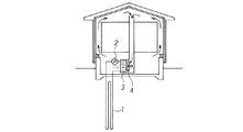
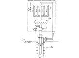
図3は特許文献1に記載された空調システムの構成図で、1は地中配管(地中埋設パイプ)、2は液体の循環ポンプ、3は熱交換器、4は送風機である。この空調システムでは地中配管1に液体を通し、その液体に地中熱を与えて熱交換器3に循環させ、送風機4により液体と熱交換した空気を建物の床下、壁体内部、屋根裏等に循環させることにより建物の内部を冷暖房するのである。地中配管1の敷設は、地下の中深部に垂直にボーリングを行なうとしている。液体は、例えば水である。
First, the air conditioning system described in Patent Document 1 will be briefly described with reference to the drawings.
FIG. 3 is a configuration diagram of an air conditioning system described in Patent Document 1. 1 is an underground pipe (underground pipe), 2 is a liquid circulation pump, 3 is a heat exchanger, and 4 is a blower. In this air conditioning system, a liquid is passed through the underground pipe 1, the ground heat is given to the liquid and circulated through the
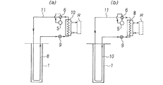
つづいて特許文献2に記載された地中熱利用システムを図面により簡単に説明する。図4は特許文献2に記載された地中熱利用空調システムの実施例のうち、(a)は冷房運転の状態、(b)は暖房運転の状態を示す構成図で、5は圧縮機、6は四方弁、8は凝縮器、9は膨張弁、10は蒸発器、11は冷媒用配管、Rは被空調空間である。
この地中熱利用空調システムは、地中に埋設された地中熱交換器(地中配管)1とヒートポンプとの間を熱交換可能に連結し、ヒートポンプと被空調空間および大気との熱交換器とを切り換え可能に連結し、地中熱交換器、ヒートポンプ、被空調空間とを連結して地中に放熱、あるいは採熱しながら被空調空間を冷暖房するもので、ヒートポンプは圧縮機5、凝縮器8、膨張弁9、蒸発器10、これらを接続して冷媒を循環させる冷媒用配管11ならびに冷媒の流れを正逆に切り換える四方弁6で構成され、(a)では地中熱交換器内1に満たされた充填材と熱交換する冷媒用配管11がヒートポンプの凝縮器8として機能し、地中に放熱し、ヒートポンプの蒸発器10と被空調空間7との間で熱交換して被空調空間7を冷房する。また(b)では、地中熱交換器内に満たされた充填材と熱交換する冷媒用配管11がヒートポンプの蒸発器10として機能し、地中から採熱し、ヒートポンプの凝縮器8と被空調空間7との間で熱交換して被空調空間7を暖房する。
Next, the geothermal heat utilization system described in
This underground heat-utilizing air conditioning system connects the underground heat exchanger (underground piping) 1 buried in the ground and the heat pump so that heat exchange is possible, and exchanges heat between the heat pump, the air-conditioned space, and the atmosphere. The heat pump is connected to the underground heat exchanger, heat pump, and air-conditioned space to heat and cool the air-conditioned space while dissipating heat or collecting heat. 8, an expansion valve 9, an
なお、地中熱交換器1は、地中に形成されるボアホール、杭基礎、直接基礎、地中連続壁等の地中地盤に接するすべての部材に適用可能であるとしており、また充填材は地中熱交換器1内に満たされる水やグラウト等である。
一方、特許文献3には、フィン付きの二重管を地中に埋設し、この二重管の内管に冷媒循環ポンプ、リザーバ、熱交換器をこの順に接続し、外管に前記の熱交換器を接続し、これらの循環系に冷媒を封入して循環させる地中熱利用冷暖房装置が記載されている。図5によりこれを簡単に説明する。1aは地中に埋設されたフィン付きの二重管、2は循環ポンプ、3は熱交換器、4は送風機、8aは冷媒のリザーバである。循環ポンプ2により二重管1aの内管に送り込まれた冷媒は、外管に回って周囲の地盤と熱交換しながら地上の熱交換器3に戻り、ここで送風機4により被空調空間と熱交換して空調を行い、リザーバ8aで液化して再び循環ポンプ2で二重管1aに送り込まれる。
The underground heat exchanger 1 is applicable to all members in contact with the ground such as boreholes, pile foundations, direct foundations, and underground continuous walls formed in the ground. It is the water, grout, etc. with which the underground heat exchanger 1 is filled.
On the other hand, in
この他、これまでの地中熱交換器に代えて2基の井戸を掘り、一方を地中熱採取用の揚水井戸、他方を戻り水の還元井戸として使用する地中熱利用システムも一部で実施されている。
ところで、従来提案されているこれらの地中熱利用システムにおいては、地盤との熱交換を行なう地中配管について、単に「地中管を埋設する」としてその形態を特定していないものや、あるいは基礎杭の内部空間等を利用するもの、別個に井戸を掘削するなどがみられたが、いずれも施工に多大な費用を要したり、すでに完成している建物には適用できないものであった。別個に井戸を掘削する方式では揚水井戸においては地下水位低下の問題があり、還元井戸においては周辺の地盤汚染の問題がある。
In addition, some geothermal heat utilization systems that dig two wells instead of the conventional underground heat exchanger, use one as a pumping well for collecting ground heat and the other as a return water reduction well. Has been implemented in.
By the way, in these underground heat utilization systems that have been proposed in the past, the underground piping that performs heat exchange with the ground is not specified as simply “embed the underground pipe”, or Some of them used the internal space of the foundation piles, and other wells were excavated separately, but all of them were expensive and could not be applied to already completed buildings. . In the method of excavating wells separately, there is a problem of lowering the groundwater level in the pumping well, and there is a problem of surrounding soil contamination in the reduction well.
既設の構造物の下部に配管を埋設するには、一般に配管の両端となる位置に立坑を設け、ここから水平ボーリングや推進工法等によって水平方向に管体を敷設するのであるが、立坑の設置には膨大な工事費がかかり、周辺の交通にも障害が発生するなど、さまざまな問題点がある。
ところが近年米国で、可撓性の連結用ロッドを備えた非開削式ボーリング機が開発され、立坑を設けなくても任意の形状で、例えば円弧状などのボーリングが可能となった。このようなボーリング機の一例ならびにそれを使用する工法が特許文献4に記載されている。
In order to embed pipes in the lower part of an existing structure, a vertical shaft is generally provided at both ends of the pipe, and pipes are laid in the horizontal direction by horizontal boring, propulsion method, etc. There are various problems such as a huge construction cost and obstacles in the surrounding traffic.
However, in recent years, a non-cutting boring machine equipped with a flexible connecting rod has been developed in the United States, and boring in an arbitrary shape, for example, an arc shape, is possible without providing a shaft. An example of such a boring machine and a construction method using the boring machine are described in Patent Document 4.
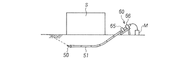
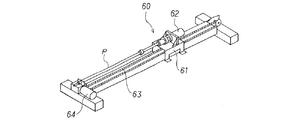
このボーリング機には、先端部が軸に対して斜めにカットされた特殊な形状の掘進ヘッドが取り付けられており、これを回転させながら前進させれば直線状の削孔が行なわれるが、回転させずに前進させると斜めにカットされた面が土圧を受けるので斜め方向に進むという特徴がある。図6は掘進機60を使用して既設の構造物Sの直下をボーリングする場合の概念図で、50は掘進ヘッド、51は可撓性の連結用ロッド、65は掘進機60のクランプ、66は同じくチャックである。また、図7は掘進機60の外観図で、61は前進フレーム、62は回転用モータ、63はチェーン、64は前進用モータ、Pは掘進させる管体、Mは滑剤等を使用する場合の薬液タンクである。前進フレーム61には前記のクランプ65およびチャック66が設けられており、クランプ65で管体Pの回転を拘束したまま前進させると先端の掘進ヘッド50は斜め方向に向かい、チャック66で回転自在に保持して前進させると先端の掘進ヘッド50は直進する。
本発明は、立坑の設置や井戸の掘削などの施工場所に制約を受ける工事を必要とせず、また既設の建物の下部にも施工が可能な地中配管による地中熱利用システムを実現することを目的とする。 The present invention realizes a ground heat utilization system using underground piping that does not require construction that is constrained by the construction site such as installation of a vertical shaft or excavation of a well, and that can also be constructed in the lower part of an existing building. With the goal.
本発明は、このようなボーリング機により円弧状の配管を地中に埋設する地中熱利用システムである。
すなわち、本発明は、地中に埋設した地中配管内と地上の熱交換器との間に液体を循環させ、熱交換器から得られる熱により建物内の被空調空間を冷暖房する地中熱利用空調システムにおいて、前記地中配管が、建物の敷地の外側から斜め方向に地中に進入し建物の下部で恒温層に到達した所で水平に転じ、建物の下部を通過した所で地上に向けて斜め方向に上昇する立坑なしの屈曲ボーリングで敷設されたものであることを特徴とする地中熱利用空調システム、あるいは、地中に埋設した地中配管と、地上の膨張弁、熱交換器、圧縮機、四方弁とを切り換え可能に接続して冷媒を循環させ、熱交換器から得られる熱により建物内の被空調空間を冷暖房する地中熱利用空調システムにおいて、前記地中配管が、建物の敷地の外側から斜め方向に地中に進入し建物の下部で恒温層に到達した所で水平に転じ、建物の下部を通過した所で地上に向けて斜め方向に上昇する立坑なしの屈曲ボーリングで敷設されたものであることを特徴とする地中熱利用空調システムである。
The present invention is a geothermal heat utilization system in which an arc-shaped pipe is buried in the ground by such a boring machine.
That is, the present invention circulates a liquid between the underground pipe buried in the ground and the heat exchanger on the ground, and uses the heat obtained from the heat exchanger to cool and heat the air-conditioned space in the building. In the use air conditioning system, the underground pipe enters the ground obliquely from the outside of the building site , turns horizontally when it reaches the constant temperature layer at the bottom of the building, and then reaches the ground when it passes through the bottom of the building. and underground piping buried geothermal heat air conditioning systems, or in the ground is characterized in that laid in bent boring without pit rises obliquely towards ground of the expansion valve, heat exchanger In the geothermal heat-conditioning air conditioning system in which the air-conditioning space in the building is cooled and heated by the heat obtained from the heat exchanger by connecting the heat exchanger, the compressor, and the four-way valve in a switchable manner, the underground pipe , oblique direction from the outside of the building site Turned horizontally enter in the ground where it reached a constant temperature bath at the bottom of the building, that where passing through the lower part of the building in which laid at the bending boring without pit rises obliquely towards the ground This is an air conditioning system using geothermal heat.
本発明によれば、地中熱を利用する経済的な空調システムが、既存の建物等においても容易に採用できることとなり、省エネルギーとコスト削減が実現するという、すぐれた効果を奏する。 According to the present invention, an economical air-conditioning system that uses geothermal heat can be easily adopted even in existing buildings and the like, and there is an excellent effect that energy saving and cost reduction are realized.
本発明は、建物の敷地の外側から地中に進入し建物の下部に自在の形状に敷設された地中配管、例えば建物の下部を横断して略円弧状に敷設された地中配管を熱交換器とする地中熱利用空調システムである。このような地中配管は、前記した特殊な掘進ヘッドと可撓性の連結用ロッドを使用するボーリングで実現することができる。すなわち、建物の敷地の外側から斜め方向にボーリングし、深さが恒温層に到達したらボーリング方向を水平に転じ、建物の下部を通過したら再び地上に向けて斜め方向とし、略円弧状にボーリングを行なうことができる。このように斜め−水平−斜めの組合せで略円弧状としてもよいし、終始一定の曲率で円弧状にボーリングしてもよい。また、伝熱面積を大きくするため、建物の下部にS字状や渦巻き状に配管を敷設してもよい。要は立坑なしの屈曲ボーリングで、建物の下部の恒温層内に管体を埋設すればよいのである。 The present invention heats underground piping that enters the ground from the outside of the building site and is laid in a free shape in the lower part of the building, for example, underground piping that is laid in a substantially arc shape across the lower part of the building. This is an air conditioning system using geothermal heat as an exchanger. Such underground piping can be realized by boring using the above-described special excavation head and a flexible connecting rod. In other words, boring from the outside of the building site in an oblique direction, when the depth reaches the constant temperature layer, the boring direction is turned horizontally, and after passing through the lower part of the building, the boring direction is made obliquely toward the ground again, and the boring is performed in a substantially arc shape. Can be done. Thus, it may be a substantially arc shape by a diagonal-horizontal-diagonal combination, or may be bored in an arc shape with a constant curvature from beginning to end. In order to increase the heat transfer area, piping may be laid in an S shape or a spiral in the lower part of the building. In short, it is a bent boring without a shaft, and it is only necessary to embed the pipe body in the thermostatic layer at the bottom of the building.
掘進に使用する可撓性のロッドを管状体として地中に残しそのまま配管に使用してもよいし、貫通後に掘進ヘッドに新たな管体を連結して引き戻し、この新たな管体を地中に敷設してもよい。
この工法によれば立坑を設ける必要がないので経済的であるばかりでなく、既設の建物に対して施工できるのは大きな利点である。
The flexible rod used for excavation may be left in the ground as a tubular body and used for piping as it is, or after penetrating, a new tubular body is connected to the excavation head and pulled back, and this new tubular body is underground. You may lay it on.
According to this construction method, it is not only economical because there is no need to provide a shaft, but it is a great advantage that it can be applied to an existing building.
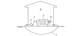
本発明の第1の実施例を図1により説明する。この図は第1の実施例の空調システムの構成図で、各符号はこれまでの説明と同じであり、1は地中配管、2は循環ポンプ、3は熱交換器、4は送風機、7は循環タンク、Rは被空調空間である。
すなわち、地中(いうまでもなく恒温層内である)に埋設した地中配管1内と地上の熱交換器3との間に液体を循環させ、熱交換器3から得られる熱により建物内の被空調空間Rを冷暖房する地中熱利用空調システムであって、前記地中配管1が、建物の敷地の外側から地中に進入し、建物の下部を横断して略円弧状に敷設されている。地中配管の管体としては、金属管、樹脂管等の強度ならびに熱伝導のよいものが好適である。管体の形状も通常の円筒状のほか、ひれ付き管や星型断面のものなど、表面積を大きくして十分に熱交換を行なえるようにしたものは、より好適である。場合によっては、図5で説明したような二重管を使用してもよい。
A first embodiment of the present invention will be described with reference to FIG. This figure is a block diagram of the air conditioning system of the first embodiment, and each symbol is the same as the description so far. 1 is an underground pipe, 2 is a circulation pump, 3 is a heat exchanger, 4 is a blower, 7 Is a circulation tank, and R is an air-conditioned space.
That is, a liquid is circulated between the underground pipe 1 buried in the ground (of course in the constant temperature layer) and the
なお、地中配管1ならびに熱交換器3を結ぶ一連の配管内を循環させる液体としては、例えば水、あるいは流動性にすぐれ、比熱の小さい薬液などがよい。地中配管1を経由して地盤内の地下温度となった液体が熱交換器3に流入するので、送風機4により熱交換を促進すれば、夏季であれば室温よりもはるかに低い約15℃の冷風が吹き出し、冬季であれば外気よりも高く、目標温度に近い約15℃の温風が吹き出すことになる。しかし地中温度にほぼ等しい温度の液体を循環させるだけであるから、これを超える高温や低温での空調は実現できない。
In addition, as a liquid circulated through a series of pipes connecting the underground pipe 1 and the
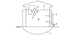
本発明の第2の実施例を図2により説明する。この図は第2の実施例の空調システムの構成図で、各符号はこれまでの説明と同じであり、5は圧縮機、6は管路を切り換える四方弁、9は膨張弁、11は冷媒用配管である。
この実施例では、地中に埋設した地中配管1と、地上の膨張弁9、熱交換器3、圧縮機5、四方弁7とを切り換え可能に接続して内部にフレオン、アンモニア、二酸化炭素等の冷媒(塩化カルシウム等のいわゆる「ブライン」を含む)を循環させ、熱交換器3から得られる冷熱あるいは温熱により建物内の被空調空間Rの冷暖房を行なう。冷媒を使用していわゆるヒートポンプの運転サイクルを実施するので、冷房運転時と暖房運転時とでは四方弁7によって冷媒の循環方向を切り換える必要がある。図2において矢印aは冷房運転時、矢印bは暖房運転時である。循環させる液体として冷媒を使用し、気化した冷媒を圧縮機で高圧に圧縮するため、地中温度に直接左右されない任意の温度が実現でき、建物内の空調だけでなく冷凍庫等にも採用できる。
A second embodiment of the present invention will be described with reference to FIG. This figure is a block diagram of the air conditioning system of the second embodiment, where each reference numeral is the same as the description so far, 5 is a compressor, 6 is a four-way valve for switching the pipeline, 9 is an expansion valve, and 11 is a refrigerant. Piping.
In this embodiment, the underground pipe 1 buried in the ground and the expansion valve 9, the
この実施例でも、地中配管は建物の敷地の外側から地中に進入し、建物の下部を横断して略円弧状に敷設されたものであるが、前記したように配管の形状は必要に応じてこの他にも任意に選定することができる。 Even in this embodiment, the underground pipe enters the ground from the outside of the building site and is laid in a substantially arc shape across the lower part of the building. However, as described above, the shape of the pipe is necessary. Other than this, it can be arbitrarily selected.
1 地中配管(地中熱交換器)
1a 二重管
2 循環ポンプ
3 熱交換器
4 送風機
5 圧縮機
6 四方弁
7 循環タンク
8 凝縮器
8a リザーバ
9 膨張弁
10 蒸発器
11 冷媒用配管
50 掘進ヘッド
51 連結用ロッド
60 掘進機
61 前進フレーム
62 回転用モータ
63 チェーン
64 前進用モータ
65 クランプ
66 チャック
M 薬液タンク
P 管体
R 被空調空間
S 構造物
1 Underground piping (Ground heat exchanger)
1a
8a Reservoir 9
Claims (2)
Priority Applications (1)
| Application Number | Priority Date | Filing Date | Title |
|---|---|---|---|
| JP2005250990A JP4632905B2 (en) | 2005-08-31 | 2005-08-31 | Geothermal air conditioning system |
Applications Claiming Priority (1)
| Application Number | Priority Date | Filing Date | Title |
|---|---|---|---|
| JP2005250990A JP4632905B2 (en) | 2005-08-31 | 2005-08-31 | Geothermal air conditioning system |
Publications (2)
| Publication Number | Publication Date |
|---|---|
| JP2007064549A JP2007064549A (en) | 2007-03-15 |
| JP4632905B2 true JP4632905B2 (en) | 2011-02-16 |
Family
ID=37926947
Family Applications (1)
| Application Number | Title | Priority Date | Filing Date |
|---|---|---|---|
| JP2005250990A Expired - Fee Related JP4632905B2 (en) | 2005-08-31 | 2005-08-31 | Geothermal air conditioning system |
Country Status (1)
| Country | Link |
|---|---|
| JP (1) | JP4632905B2 (en) |
Families Citing this family (8)
| Publication number | Priority date | Publication date | Assignee | Title |
|---|---|---|---|---|
| JP4987610B2 (en) * | 2007-07-31 | 2012-07-25 | 株式会社前川製作所 | Geothermal heat pump cycle equipment |
| KR20100123927A (en) * | 2008-04-30 | 2010-11-25 | 다이킨 고교 가부시키가이샤 | Heat exchanger and air conditioning system |
| CA2759437A1 (en) * | 2009-04-20 | 2010-10-28 | Anzoic Energy Inc. | Subterranean continuous loop heat exchanger, method of manufacture and method to heat, cool or store energy with same |
| JP2010266127A (en) * | 2009-05-14 | 2010-11-25 | Fujishima Kensetsu:Kk | Heat pump air conditioner |
| JP2011142056A (en) * | 2010-01-08 | 2011-07-21 | Nemoto Kikaku Kogyo Kk | Ground electrode and its construction method |
| CN103759361B (en) * | 2014-01-21 | 2018-11-16 | 吴刚 | Ground source central air conditioner system |
| JP7010751B2 (en) * | 2018-04-04 | 2022-01-26 | 鹿島建設株式会社 | How to bury a geothermal heat exchanger |
| JP2020070960A (en) * | 2018-10-30 | 2020-05-07 | 国立大学法人秋田大学 | Horizontal underground heat exchanger, and air conditioning system using underground heat |
Family Cites Families (3)
| Publication number | Priority date | Publication date | Assignee | Title |
|---|---|---|---|---|
| JPS57148126A (en) * | 1981-03-07 | 1982-09-13 | Hiroyuki Morita | Underground heat exchanging equipment |
| JP3755472B2 (en) * | 2002-03-08 | 2006-03-15 | 強化土エンジニヤリング株式会社 | Ground improvement method |
| JP2005048972A (en) * | 2003-07-29 | 2005-02-24 | Nippon Steel Corp | Geothermal utilization system |
-
2005
- 2005-08-31 JP JP2005250990A patent/JP4632905B2/en not_active Expired - Fee Related
Also Published As
| Publication number | Publication date |
|---|---|
| JP2007064549A (en) | 2007-03-15 |
Similar Documents
| Publication | Publication Date | Title |
|---|---|---|
| JP4535981B2 (en) | Tunnel heat exchange panel and tunnel heat utilization heat exchange system | |
| JP4642579B2 (en) | Geothermal heat collection system | |
| US7146823B1 (en) | Horizontal and vertical direct exchange heating/cooling system sub-surface tubing installation means | |
| US6932149B2 (en) | Insulated sub-surface liquid line direct expansion heat exchange unit with liquid trap | |
| JP2010261633A (en) | Multiple tubes for heat exchange and air-conditioning system using underground heat using the same | |
| JP6009138B2 (en) | Geothermal utilization system | |
| KR101535384B1 (en) | Heating system of heat pump using solar energy and underground heat storage | |
| JP3375474B2 (en) | Heat pump air conditioning system using underground thermal convection layer | |
| JP2008292107A (en) | HEAT EXCHANGER, HEAT EXCHANGE SYSTEM AND HEAT EXCHANGE SYSTEM CONSTRUCTION METHOD | |
| JP2010060247A (en) | Soil heat exchanger of heat pump system using soil heat | |
| JP4632905B2 (en) | Geothermal air conditioning system | |
| JP2005049016A (en) | Geothermal heat pump system | |
| KR101641507B1 (en) | Cooling heating system using heat exchanged bleeding underground water | |
| AU2009241159A1 (en) | Heat exchanger and air conditioning system | |
| JP2008014530A (en) | Heat pump device using wells | |
| JP2003262430A (en) | Geothermal heat pump | |
| JP2005127612A (en) | Groundwater tank water source heat pump ground heat utilization system | |
| JP4981516B2 (en) | HEAT EXCHANGER, HEAT EXCHANGE SYSTEM, HEAT EXCHANGER MANUFACTURING METHOD, AND HEAT EXCHANGE SYSTEM CONSTRUCTION METHOD | |
| JP2014115016A (en) | Geothermal utilization heating and cooling system | |
| JP5389565B2 (en) | Geothermal air conditioning system | |
| JP6738596B2 (en) | Underground heat exchange mechanism | |
| JP2001289533A (en) | Geothermal heat pump | |
| JP2006145059A (en) | Hybrid type underground heat utilization heat pump device and its operating method | |
| US20100251710A1 (en) | System for utilizing renewable geothermal energy | |
| JP7359361B2 (en) | heat pump equipment |
Legal Events
| Date | Code | Title | Description |
|---|---|---|---|
| A621 | Written request for application examination |
Free format text: JAPANESE INTERMEDIATE CODE: A621 Effective date: 20070423 |
|
| A977 | Report on retrieval |
Free format text: JAPANESE INTERMEDIATE CODE: A971007 Effective date: 20100312 |
|
| A131 | Notification of reasons for refusal |
Free format text: JAPANESE INTERMEDIATE CODE: A131 Effective date: 20100406 |
|
| A521 | Request for written amendment filed |
Free format text: JAPANESE INTERMEDIATE CODE: A523 Effective date: 20100604 |
|
| RD13 | Notification of appointment of power of sub attorney |
Free format text: JAPANESE INTERMEDIATE CODE: A7433 Effective date: 20100604 |
|
| A521 | Request for written amendment filed |
Free format text: JAPANESE INTERMEDIATE CODE: A821 Effective date: 20100604 |
|
| TRDD | Decision of grant or rejection written | ||
| A01 | Written decision to grant a patent or to grant a registration (utility model) |
Free format text: JAPANESE INTERMEDIATE CODE: A01 Effective date: 20101116 |
|
| A01 | Written decision to grant a patent or to grant a registration (utility model) |
Free format text: JAPANESE INTERMEDIATE CODE: A01 |
|
| A61 | First payment of annual fees (during grant procedure) |
Free format text: JAPANESE INTERMEDIATE CODE: A61 Effective date: 20101116 |
|
| R150 | Certificate of patent or registration of utility model |
Ref document number: 4632905 Country of ref document: JP Free format text: JAPANESE INTERMEDIATE CODE: R150 Free format text: JAPANESE INTERMEDIATE CODE: R150 |
|
| FPAY | Renewal fee payment (event date is renewal date of database) |
Free format text: PAYMENT UNTIL: 20131126 Year of fee payment: 3 |
|
| R250 | Receipt of annual fees |
Free format text: JAPANESE INTERMEDIATE CODE: R250 |
|
| R250 | Receipt of annual fees |
Free format text: JAPANESE INTERMEDIATE CODE: R250 |
|
| R250 | Receipt of annual fees |
Free format text: JAPANESE INTERMEDIATE CODE: R250 |
|
| R250 | Receipt of annual fees |
Free format text: JAPANESE INTERMEDIATE CODE: R250 |
|
| LAPS | Cancellation because of no payment of annual fees |