JP4632049B2 - Video coding method and apparatus - Google Patents
Video coding method and apparatus Download PDFInfo
- Publication number
- JP4632049B2 JP4632049B2 JP2005516646A JP2005516646A JP4632049B2 JP 4632049 B2 JP4632049 B2 JP 4632049B2 JP 2005516646 A JP2005516646 A JP 2005516646A JP 2005516646 A JP2005516646 A JP 2005516646A JP 4632049 B2 JP4632049 B2 JP 4632049B2
- Authority
- JP
- Japan
- Prior art keywords
- frame
- frames
- image quality
- encoding
- picture
- Prior art date
- Legal status (The legal status is an assumption and is not a legal conclusion. Google has not performed a legal analysis and makes no representation as to the accuracy of the status listed.)
- Expired - Fee Related
Links
Images


Classifications
-
- H—ELECTRICITY
- H04—ELECTRIC COMMUNICATION TECHNIQUE
- H04N—PICTORIAL COMMUNICATION, e.g. TELEVISION
- H04N19/00—Methods or arrangements for coding, decoding, compressing or decompressing digital video signals
- H04N19/50—Methods or arrangements for coding, decoding, compressing or decompressing digital video signals using predictive coding
- H04N19/503—Methods or arrangements for coding, decoding, compressing or decompressing digital video signals using predictive coding involving temporal prediction
- H04N19/51—Motion estimation or motion compensation
- H04N19/577—Motion compensation with bidirectional frame interpolation, i.e. using B-pictures
-
- H—ELECTRICITY
- H04—ELECTRIC COMMUNICATION TECHNIQUE
- H04N—PICTORIAL COMMUNICATION, e.g. TELEVISION
- H04N19/00—Methods or arrangements for coding, decoding, compressing or decompressing digital video signals
- H04N19/10—Methods or arrangements for coding, decoding, compressing or decompressing digital video signals using adaptive coding
- H04N19/102—Methods or arrangements for coding, decoding, compressing or decompressing digital video signals using adaptive coding characterised by the element, parameter or selection affected or controlled by the adaptive coding
- H04N19/103—Selection of coding mode or of prediction mode
- H04N19/105—Selection of the reference unit for prediction within a chosen coding or prediction mode, e.g. adaptive choice of position and number of pixels used for prediction
-
- H—ELECTRICITY
- H04—ELECTRIC COMMUNICATION TECHNIQUE
- H04N—PICTORIAL COMMUNICATION, e.g. TELEVISION
- H04N19/00—Methods or arrangements for coding, decoding, compressing or decompressing digital video signals
- H04N19/10—Methods or arrangements for coding, decoding, compressing or decompressing digital video signals using adaptive coding
- H04N19/102—Methods or arrangements for coding, decoding, compressing or decompressing digital video signals using adaptive coding characterised by the element, parameter or selection affected or controlled by the adaptive coding
- H04N19/115—Selection of the code volume for a coding unit prior to coding
-
- H—ELECTRICITY
- H04—ELECTRIC COMMUNICATION TECHNIQUE
- H04N—PICTORIAL COMMUNICATION, e.g. TELEVISION
- H04N19/00—Methods or arrangements for coding, decoding, compressing or decompressing digital video signals
- H04N19/10—Methods or arrangements for coding, decoding, compressing or decompressing digital video signals using adaptive coding
- H04N19/102—Methods or arrangements for coding, decoding, compressing or decompressing digital video signals using adaptive coding characterised by the element, parameter or selection affected or controlled by the adaptive coding
- H04N19/124—Quantisation
-
- H—ELECTRICITY
- H04—ELECTRIC COMMUNICATION TECHNIQUE
- H04N—PICTORIAL COMMUNICATION, e.g. TELEVISION
- H04N19/00—Methods or arrangements for coding, decoding, compressing or decompressing digital video signals
- H04N19/10—Methods or arrangements for coding, decoding, compressing or decompressing digital video signals using adaptive coding
- H04N19/134—Methods or arrangements for coding, decoding, compressing or decompressing digital video signals using adaptive coding characterised by the element, parameter or criterion affecting or controlling the adaptive coding
- H04N19/157—Assigned coding mode, i.e. the coding mode being predefined or preselected to be further used for selection of another element or parameter
-
- H—ELECTRICITY
- H04—ELECTRIC COMMUNICATION TECHNIQUE
- H04N—PICTORIAL COMMUNICATION, e.g. TELEVISION
- H04N19/00—Methods or arrangements for coding, decoding, compressing or decompressing digital video signals
- H04N19/10—Methods or arrangements for coding, decoding, compressing or decompressing digital video signals using adaptive coding
- H04N19/169—Methods or arrangements for coding, decoding, compressing or decompressing digital video signals using adaptive coding characterised by the coding unit, i.e. the structural portion or semantic portion of the video signal being the object or the subject of the adaptive coding
- H04N19/17—Methods or arrangements for coding, decoding, compressing or decompressing digital video signals using adaptive coding characterised by the coding unit, i.e. the structural portion or semantic portion of the video signal being the object or the subject of the adaptive coding the unit being an image region, e.g. an object
- H04N19/172—Methods or arrangements for coding, decoding, compressing or decompressing digital video signals using adaptive coding characterised by the coding unit, i.e. the structural portion or semantic portion of the video signal being the object or the subject of the adaptive coding the unit being an image region, e.g. an object the region being a picture, frame or field
-
- H—ELECTRICITY
- H04—ELECTRIC COMMUNICATION TECHNIQUE
- H04N—PICTORIAL COMMUNICATION, e.g. TELEVISION
- H04N19/00—Methods or arrangements for coding, decoding, compressing or decompressing digital video signals
- H04N19/30—Methods or arrangements for coding, decoding, compressing or decompressing digital video signals using hierarchical techniques, e.g. scalability
- H04N19/31—Methods or arrangements for coding, decoding, compressing or decompressing digital video signals using hierarchical techniques, e.g. scalability in the temporal domain
-
- H—ELECTRICITY
- H04—ELECTRIC COMMUNICATION TECHNIQUE
- H04N—PICTORIAL COMMUNICATION, e.g. TELEVISION
- H04N19/00—Methods or arrangements for coding, decoding, compressing or decompressing digital video signals
- H04N19/50—Methods or arrangements for coding, decoding, compressing or decompressing digital video signals using predictive coding
- H04N19/503—Methods or arrangements for coding, decoding, compressing or decompressing digital video signals using predictive coding involving temporal prediction
- H04N19/51—Motion estimation or motion compensation
- H04N19/573—Motion compensation with multiple frame prediction using two or more reference frames in a given prediction direction
Description
本発明は、動画像符号化技術に関し、特に、マルチフレーム動き予測を行う動画像符号化方法及び装置に関する。 The present invention relates to a moving picture coding technique, and more particularly to a moving picture coding method and apparatus for performing multiframe motion prediction.
図1は、動画像信号を符号化する従来の典型的な符号化装置の構成を示すブロック図である。 FIG. 1 is a block diagram showing a configuration of a conventional typical encoding apparatus that encodes a moving image signal.
図1に示される符号化装置は、局所的復号装置を含んでおり、周波数変換装置101、量子化装置102、可変長符号化装置103、逆量子化装置104、逆周波数変換装置105、フレームメモリ106、フレーム内予測装置107、動き補償装置108、動き推定装置109、バッファ110および符号量制御装置111を備えている。さらに符号化装置は、減算器121、スイッチ122および加算器123を備えている。
The encoding apparatus shown in FIG. 1 includes a local decoding apparatus, and includes a
入力画像フレームは、符号化装置に入力されて、複数のブロックに分割される。分割されたブロックは、減算器121によって、フレーム内予測あるいはフレーム間予測による予測値が減じられる。ここで、フレーム内予測とは、現在の符号化フレームの再構築領域を用いて現在の画像を予測する方法であり、フレーム間予測とは、過去に再構築された画像フレームを用いて現在の画像を予測する方法である。フレーム内予測あるいはフレーム間予測による予測値が減じられた画像ブロックを予測誤差と呼ぶ。なお、同一符号化フレームの隣接画素から予測値を生成するフレーム内予測のみで符号化フレーム内の全てのブロックを符号化した画像フレームをIピクチャと呼ぶ。フレーム内予測とフレーム間予測とを混在して用いて符号化された画像フレームをPピクチャと呼ぶ。さらに、フレーム間予測において、現在の符号化フレームに対して入力時刻が過去と未来である複数の画像フレームを参照して符号化された画像フレームを、Bピクチャと呼ぶ。
The input image frame is input to the encoding device and divided into a plurality of blocks. The
一般に、符号化動画像データにおいて、Iピクチャは一定周期で設定され、このIピクチャで区切られる複数フレームからなる区間をGOP(グループオブピクチャ;Group Of Picture)と呼ぶ。I,P,BピクチャおよびGOPの定義は、国際標準の動画像符号化規格であるMPEG(Motion Picture Expert Group)方式などで定められている。 In general, in encoded moving image data, an I picture is set at a fixed period, and a section composed of a plurality of frames divided by the I picture is called a GOP (Group Of Picture). Definitions of I, P, B picture and GOP are defined by MPEG (Motion Picture Expert Group) system which is an international standard moving picture coding standard.
次に、予測誤差は、周波数変換装置101によって周波数領域に変換される。周波数領域に変換された予測誤差は、量子化装置102によって量子化される。量子化された予測誤差すなわち変換係数は、可変長符号化装置103によってエントロピー符号化され、バッファ110に蓄積される。バッファ110は、蓄積した発生符号すなわちビットストリームを所定のタイミングで出力する。また、量子化された予測誤差は、局所的復号処理として、逆量子化装置104および逆周波数変換装置105により、再び元の空間領域の予測誤差に戻される。さらに空間領域に戻された予測誤差は、加算器123により予測値を加えられ、再構築画像としてフレームメモリ106に格納される。
Next, the prediction error is converted into the frequency domain by the
フレームメモリ106に格納された再構築画像は、フレーム内予測装置107、動き補償装置108および動き推定装置109によって予測値の生成に参照される。よってフレームメモリ106に格納された再構築画像は参照フレームとも呼ばれる。
The reconstructed image stored in the
フレーム内予測装置107は、フレームメモリ107内の再構築画像に基づいてフレーム内予測を行い、予測値を出力する。動き推定装置109は、入力画像のブロックとフレームメモリ106から読み出される参照フレームとから、入力ブロックと予測値との差分すなわち予測誤差を最小にする、入力ブロックの動きベクトルと参照フレームとを検出する。動き補償装置108は、動き推定装置109から供給される動きベクトルと参照フレームを用いて、フレームメモリ106に格納された参照フレームから予測値を生成する。動き補償装置109による予測値はフレーム間予測に基づくものである。そこで、スイッチ122を設け、フレーム内予測装置107が出力する予測値と動き補償装置108が出力する予測値のうち、減算器121に供給される予測値を切り替えられるようにしている。
The
上記の処理によって圧縮された動画像情報であるビットストリームは、主にブロックごとの変換係数、量子化パラメータ、(予測誤差を最小にする)動きベクトル、および(予測誤差を最小にする)参照フレームからなる可変長符号によって構成されている。 The bit stream which is the moving image information compressed by the above processing is mainly composed of transform coefficients for each block, quantization parameters, motion vectors (which minimize the prediction error), and reference frames (which minimize the prediction error). It is comprised by the variable length code which consists of.
以上は、動画像圧縮技術の基本動作である。 The above is the basic operation of the moving image compression technique.
ところで、一般に、デジタル放送システムや画像通信サービスなどにおいて、動画像信号は、伝送・蓄積のために、その発生符号量すなわちビットレートが制御されている。そこで、符号量制御装置111は、可変長符号化装置103が供給する発生符号量を検出して、以下に示す2つの処理を実行して、発生符号量を制御する。
By the way, in general, in a digital broadcasting system, an image communication service, and the like, the generated code amount, that is, the bit rate of a moving image signal is controlled for transmission and storage. Therefore, the code
第1の処理では、符号量制御器111は、各ピクチャタイプに応じて各フレームに目標符号量を設定する。RをGOP内でまだ符号化されていないフレームに対して割り当てられる符号量、NpおよびNbをそれぞれGOP内でまだ符号化されていないPピクチャとBピクチャの枚数、Xi,Xp,Xbを式(1)〜(3)で定義される各ピクチャの画面の複雑さを示すパラメータ、KpとKbをピクチャタイプ別の主観画質を考慮したパラメータであるとすると、ピクチャタイプ別の目標符号量Ti,Tp,Tbは、式(4)〜(6)で与えられる。
In the first process, the
Xi=Qi×Ci …(1),
Xp=Qp×Cp …(2),
Xb=Qb×Cb …(3),
Ti=R/(1+Np×Xp/(Kp×Xi)+Nb×Xb/(Kb×Xi)) …(4),
Tp=R/(Np+Nb×Kp×Xb/(Kb×Xp)) …(5),
Tb=R/(Nb+Np×Kb×Xp/(Kp×Xb)) …(6).
ここで、Ci,Cp,Cbは、それぞれ、最後に符号化したI,P,Bピクチャの発生符号量であり、Qi,Qp,Qbは、それぞれ、最後に符号化したI,P,Bピクチャの平均量子化ステップサイズとする。なお、以下の説明において、表記の簡単化のため、例えば、Ci,Cp,Cbのいずれかである値は、Ci,p,bのように記載する。また、Qi,p,b=Xi,p,b/Ti,p,bなる式は、Iピクチャに対するQi=Xi/Tiという式と、Pピクチャに対するQp=Xp/Tpという式と、Bピクチャに対するQb=Xb/Tbという式とをまとめて示している。Xi = Qi × Ci (1),
Xp = Qp × Cp (2),
Xb = Qb × Cb (3),
Ti = R / (1 + Np × Xp / (Kp × Xi) + Nb × Xb / (Kb × Xi)) (4),
Tp = R / (Np + Nb × Kp × Xb / (Kb × Xp)) (5),
Tb = R / (Nb + Np × Kb × Xp / (Kp × Xb)) (6).
Here, Ci, Cp, and Cb are the generated code amounts of the last encoded I, P, and B pictures, respectively, and Qi, Qp, and Qb are the last encoded I, P, and B pictures, respectively. Is the average quantization step size. In the following description, for simplicity of description, for example, a value that is one of Ci, Cp, and Cb is written as Ci, p, and b. Also, the expressions Qi, p, b = Xi, p, b / Ti, p, b are Qi = Xi / Ti for I picture, Qp = Xp / Tp for P picture, and B picture. The expression Qb = Xb / Tb is shown together.
各フレームを第1の処理と以下で説明する第2の処理とにしたがって符号化するごとに、GOP内でまだ符号化されていないフレームに対して割り当てられる符号量Rを式(7)に基づいて更新する。 Each time each frame is encoded according to the first process and the second process described below, the code amount R assigned to a frame that has not been encoded in the GOP is calculated based on Expression (7). Update.
R=R−Ci,p,b …(7).
また、GOP先頭のピクチャを符号化する際には、符号量Rを式(8)で初期化する。R = R-Ci, p, b (7).
Further, when encoding the GOP head picture, the code amount R is initialized by the equation (8).
R=bit_rate×N/frame_rate+R …(8).
ここで、bit_rateは目標とするビットレートであり、frame_rateはフレームレートであり、NはGOP内のフレームの枚数である。R = bit_rate × N / frame_rate + R (8).
Here, bit_rate is the target bit rate, frame_rate is the frame rate, and N is the number of frames in the GOP.
第2の処理では、第1の処理で求められた各フレームに対する割り当て符号量Ti,Tp,Tbと実際の発生符号量を一致させるために、各ピクチャタイプ別に設定した仮想バッファ容量に基づいて、量子化ステップをマクロブロック単位のフィードバック制御で求める。 In the second process, in order to match the allocated code amounts Ti, Tp, Tb for each frame obtained in the first process with the actual generated code amounts, based on the virtual buffer capacity set for each picture type, The quantization step is obtained by feedback control in units of macroblocks.
まずj番目のマクロブロックの符号化に先立ち、仮想バッファの占有量をピクチャタイプ別に式(9)でもとめる。 First, prior to encoding the j-th macroblock, the occupation amount of the virtual buffer is determined by equation (9) for each picture type.
di,p,b(j)=di,p,b(0)+B(j−1)−Ti,p,b×(j−1)/MBcount …(9).
di,p,b(0)は、仮想バッファの初期占有量であり、B(j)は、フレームの先頭からj番目のマクロブロックまでの発生符号量であり、MBcountは、フレーム内のマクロブロックの数である。di, p, b (j) = di, p, b (0) + B (j−1) −Ti, p, b × (j−1) / MBcount (9).
di, p, b (0) are the initial occupancy of the virtual buffer, B (j) is the generated code amount from the beginning of the frame to the jth macroblock, and MBcount is the macroblock in the frame. Is the number of
各フレームの符号化が終了した時、ピクチャタイプ別の仮想バッファの初期占有量di,p,b(MBcount)は、次のピクチャに対する仮想バッファの初期占有量di,p,b(0)として用いられる。 When encoding of each frame is completed, the initial occupation amount di, p, b (MBcount) of the virtual buffer for each picture type is used as the initial occupation amount di, p, b (0) of the virtual buffer for the next picture. It is done.
次に、j番目のマクロブロックに対する量子化ステップサイズQ(j)を式(10)によって、計算する。 Next, the quantization step size Q (j) for the j-th macroblock is calculated by Equation (10).
Q(j)=Qi,p,b×di,p,b(j)×31/(10×r) …(10),
Qi,p,b=Xi,p,b/Ti,p,b …(11).
rは、リアクションパラメータと呼ばれるフィードバックループの応答速度を制御するパラメータであり、式(12)で与えられる。Q (j) = Qi, p, b × di, p, b (j) × 31 / (10 × r) (10),
Qi, p, b = Xi, p, b / Ti, p, b (11).
r is a parameter that controls the response speed of the feedback loop, called a reaction parameter, and is given by equation (12).
r=2×bitrate/frame_rate …(12).
なお、符号化の開始時における仮想バッファの初期占有量di,p,b(0)は、式(13)〜(15)で与えられる。r = 2 × bitrate / frame_rate (12).
Note that the initial occupancy di, p, b (0) of the virtual buffer at the start of encoding is given by equations (13) to (15).
di(0)=10×r/31 …(13),
dp(0)=Kp×di(0) …(14),
db(0)=Kb×di(0) …(15).
一方、直前に符号化したIピクチャまたはPピクチャだけからでなくさらに過去に符号化したフレームからPピクチャを予測し、直前に符号化したIピクチャまたはPピクチャからだけでなくさらに過去に符号化したBピクチャからもBピクチャを予測するという、動き予測が可能なマルチフレーム動き予測を取り入れた動画像の符号化方式が考えられている。この方式では、過去に符号化した高画質なフレームを選択して動き予測を行えるため、動き予測の自由度が増大する。di (0) = 10 × r / 31 (13),
dp (0) = Kp × di (0) (14),
db (0) = Kb × di (0) (15).
On the other hand, a P picture is predicted from a frame encoded in the past as well as from an I picture or P picture encoded immediately before, and is encoded not only from an I picture or P picture encoded immediately before. A moving picture coding method incorporating multi-frame motion prediction capable of motion prediction, in which a B picture is predicted from a B picture, is considered. In this method, since motion prediction can be performed by selecting a high-quality frame encoded in the past, the degree of freedom in motion prediction increases.
しかしながら、上述した従来の動画像符号化技術は、マルチフレーム動き予測による動き予測の自由度を利用しないで、単純にピクチャタイプと、最後に符号化した各ピクチャの複雑度とのみで各フレームに対する割り当て符号量を制御する。このため従来の手法では、マルチフレーム動き予測を用いる動画像圧縮において、マルチフレーム動き予測を有効的に用いて動画像を高画質に符号化しているとはいえない。逆に言えば、マルチフレーム動き予測を用いる動画像圧縮において、マルチフレーム動き予測を有効的に用いることにより、動画像を高品質に符号化できる技術が望まれている。 However, the above-described conventional video encoding technology does not use the degree of freedom of motion prediction by multiframe motion prediction, and simply applies the picture type and the complexity of each picture encoded last to each frame. Controls the allocated code amount. For this reason, in the conventional technique, in moving picture compression using multi-frame motion prediction, it cannot be said that multi-frame motion prediction is effectively used to encode a moving picture with high image quality. In other words, there is a demand for a technique capable of encoding a moving image with high quality by effectively using multi-frame motion prediction in moving image compression using multi-frame motion prediction.
本発明の目的は、マルチフレーム動き予測を有効的に活用して動画像を高画質に符号化することができる動画像符号化方法を提供することにある。 An object of the present invention is to provide a moving picture coding method capable of coding a moving picture with high image quality by effectively utilizing multi-frame motion prediction.
本発明の別の目的は、マルチフレーム動き予測を有効的に活用して動画像を高画質に符号化することができる動画像符号化装置を提供することにある。 Another object of the present invention is to provide a moving picture coding apparatus capable of coding a moving picture with high image quality by effectively utilizing multi-frame motion prediction.
本発明の目的は、複数枚の画像フレームを参照してマルチフレーム動き予測を行う動画像符号化方法であって、マルチフレーム動き予測に用いる参照フレームに、同じピクチャタイプの他のフレームよりも高画質に符号化されたフレームを含めることを有する、動画像符号化方法によって達成される。 An object of the present invention is a moving image coding method for performing multiframe motion prediction with reference to a plurality of image frames, in which a reference frame used for multiframe motion prediction is higher than other frames of the same picture type. This is achieved by a moving picture coding method comprising including coded frames in the image quality.
本発明の別の目的は、複数枚の画像フレームを参照してマルチフレーム動き予測を行って符号化を行う動画像符号化装置であって、同じピクチャタイプの複数枚の参照フレームのうちから少なくとも1枚の参照フレームを選択する選択手段と、選択された参照フレームを同じピクチャタイプの他の参照フレームよりも高画質に符号化する符号化手段と、を有することを特徴とする動画像符号化装置によって達成される。 Another object of the present invention is a video encoding apparatus that performs encoding by performing multiframe motion prediction with reference to a plurality of image frames, and includes at least one of a plurality of reference frames of the same picture type. A moving picture encoding comprising: selection means for selecting one reference frame; and encoding means for encoding the selected reference frame with higher image quality than other reference frames of the same picture type Achieved by the device.
本発明では、マルチフレーム動き予測を用いる動画像圧縮において、単純にピクチャタイプと最後に符号化した各ピクチャの複雑度を利用するのではなく、マルチフレーム動き予測における符号化対象フレームと参照フレームとの関係も考慮し、参照フレームとして優先度の高いフレームを高画質に符号化することによって、シーン全体の動き予測の効果を改善するような符号量制御を行う。これにより、本発明によれば、マルチフレーム動き予測による動き予測の自由度を利用した動画像圧縮において、高画質な動画像符号化方法を実現できる。 In the present invention, in moving picture compression using multiframe motion prediction, rather than simply using the picture type and the complexity of each last encoded picture, the encoding target frame and reference frame in multiframe motion prediction are used. In consideration of the above relationship, by encoding a frame having a high priority as a reference frame with high image quality, code amount control is performed to improve the effect of motion prediction of the entire scene. Thus, according to the present invention, it is possible to realize a high-quality moving image encoding method in moving image compression using the degree of freedom of motion prediction by multiframe motion prediction.
また、動画像のシーンに応じて、高画質に符号化するフレームを一定のフレーム間隔で配置したり、高画質に符号化するフレームのフレーム間隔を、参照フレームと符号化対象フレームとの間の差分情報及び動き情報とによって適応的に変更することで、優先的に高画質に符号化する参照フレームを正確に選択することができ、より高画質な動画像の符号量制御を提供できる。この結果、さらに動画像を高画質に符号化することができる。 Also, depending on the scene of the moving image, frames that are encoded with high image quality are arranged at fixed frame intervals, or the frame intervals of frames that are encoded with high image quality are set between the reference frame and the encoding target frame. By adaptively changing the difference information and the motion information, it is possible to accurately select a reference frame that is preferentially encoded with high image quality, and it is possible to provide code amount control of a moving image with higher image quality. As a result, the moving image can be further encoded with high image quality.
また、参照フレームとして優先度の高いBピクチャフレームにより多くの符号量を割り当てることにより、高画質な動画像の符号量制御も提供できる。この結果、シーケンス全体の動き予測の効果を改善できるので、動画像を高画質に符号化することができる。 Also, by assigning a larger amount of code to a B picture frame having a higher priority as a reference frame, it is possible to provide code amount control of a high-quality moving image. As a result, the effect of motion prediction of the entire sequence can be improved, so that a moving image can be encoded with high image quality.
上述しように本発明では、マルチフレーム動き予測における符号化対象フレームと参照フレームとの関係も考慮し、参照フレームとして優先度の高いフレームを高画質に符号化することによって、シーン全体の動き予測の効果を改善するような符号量制御を行っている。 As described above, the present invention considers the relationship between the encoding target frame and the reference frame in multi-frame motion prediction, and encodes a frame having a high priority as a reference frame with high image quality. Code amount control is performed to improve the effect.
以下の説明において、「シーン」とは、任意の枚数の連続するフレームを意味する。「フレームを高画質に符号化する」とは、そのフレームに対して多くの符号量を割り当てる、そのフレームの量子化ステップサイズを小さくする、あるいは、そのフレームの符号化歪みを小さくすることなどを意味する。 In the following description, “scene” means an arbitrary number of consecutive frames. “Encode a frame with high image quality” means that a large amount of code is allocated to the frame, the quantization step size of the frame is reduced, or the encoding distortion of the frame is reduced. means.
以下に、本発明の基本原理について、従来技術と対比しながら説明する。 The basic principle of the present invention will be described below in comparison with the prior art.
本発明では、マルチフレーム動き予測を用いた動画像符号化方法において、同じピクチャタイプのフレームの画質を均一ではなく、可変とすることで、シーン全体の動き予測の効果を高め、高画質な動画像の符号化を可能にしている。これに対し、従来の動き予測方向を用いた動画像符号化方法では、直前に符号化した画像のみから動き予測を行うため、同じピクチャタイプのフレームの画質を均一に保つ符号化しか行えなかった。なぜなら、同じシーンで画質を変動させた場合、画質の低下したフレームを参照するフレームでのフレーム間の差分が大きくなって動き予測の効果が低下するため、シーン全体の符号化効率が低下し、これに伴って、符号化された動画像の画質も低下するからである。 In the present invention, in the moving picture coding method using multi-frame motion prediction, the image quality of the frame of the same picture type is not uniform but variable, so that the effect of motion prediction of the entire scene is enhanced, and high-quality video It enables image encoding. On the other hand, in the conventional video encoding method using the motion prediction direction, since motion prediction is performed only from the image encoded immediately before, only encoding that maintains uniform image quality of frames of the same picture type can be performed. . Because when the image quality is changed in the same scene, the difference between the frames in the frame that refers to the frame with the lowered image quality becomes large and the effect of motion prediction is reduced, so that the coding efficiency of the entire scene is reduced, This is because the image quality of the encoded moving image also decreases.
以下に図2を参照して、この問題点を説明する。 This problem will be described below with reference to FIG.
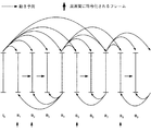
図2において実線で示すように、従来の動き予測では、各Pピクチャは、直前に符号化されたIまたはPピクチャのみを参照する。P2,P4フレームをP1,P3フレームよりも高画質に符号化しようとしても、P1フレームは低画質で符号化されるため、P1フレームを参照するP2フレームでの動き予測の効果は大きく低減し、P2フレームの画質も大きく低下する。P2フレームを参照するP3フレームも同様に画質が大きく低下し、この画質劣化が以降のフレームに伝播するため、シーン全体の画質が劣化する。このため従来の動き予測を用いた方法では、同じピクチャタイプの画像の画質を均一に保たなければならない。As shown by a solid line in FIG. 2, in the conventional motion prediction, each P picture refers to only the I or P picture coded immediately before. Even if an attempt is made to encode the P 2 and P 4 frames with higher image quality than the P 1 and P 3 frames, the P 1 frame is encoded with low image quality, and therefore motion prediction is performed in the P 2 frame that refers to the P 1 frame. effect greatly reduced, also greatly reduced quality of P 2 frames. Similarly, the image quality of the P 3 frame that refers to the P 2 frame is greatly reduced, and this image quality deterioration is propagated to the subsequent frames, so that the image quality of the entire scene is deteriorated. For this reason, in the conventional method using motion estimation, the image quality of the same picture type image must be kept uniform.
しかしながら、本発明が適用される符号化方法のように、直前に符号化されたフレームだけでなく、さらに過去に符号化したフレームを参照して動き予測が可能なマルチフレーム動き予測がある。マルチフレーム動き予測により、図2に示した場合では、従来方式に追加して、点線で示すような予測が可能となる。この場合、フレーム内の領域あるいはブロックの単位で、参照するフレームを選択できる。 However, there is a multi-frame motion prediction in which motion prediction is possible by referring to not only a frame encoded immediately before but also a frame encoded in the past, as in the encoding method to which the present invention is applied. By the multi-frame motion prediction, in the case shown in FIG. 2, prediction as indicated by a dotted line can be performed in addition to the conventional method. In this case, a frame to be referenced can be selected in units of areas or blocks in the frame.
このマルチフレーム動き予測の構造を利用することにより、同じピクチャタイプでも、画質を変動させる符号化が可能となる。図2を参照して、本発明を説明する。 By using this multi-frame motion prediction structure, it is possible to perform encoding with varying image quality even with the same picture type. The present invention will be described with reference to FIG.
図2に示すマルチフレーム動き予測では、各Pピクチャは、直前に符号化された複数のIまたはPピクチャを参照する。ここでは、2枚のIまたはPピクチャを参照している。P2,P4フレームをP1,P3フレームよりも高画質に符号化しようとしたとき、P1フレームが低画質で符号化されたとしても、P1フレームだけでなくI0フレームも参照するP2フレームでは、動き予測の効果は大きく低減しない。よって、P2フレームは高画質に符号化される。In the multi-frame motion prediction shown in FIG. 2, each P picture refers to a plurality of I or P pictures encoded immediately before. Here, two I or P pictures are referenced. When trying to encode the P 2 and P 4 frames with higher image quality than the P 1 and P 3 frames, even if the P 1 frame is encoded with lower image quality, not only the P 1 frame but also the I 0 frame is referred to. In the P 2 frame, the effect of motion prediction is not greatly reduced. Therefore, the P 2 frame is encoded with high image quality.
また、高画質に符号化されたP2フレームを参照するP3フレームでの動き予測の効果も高まり、P3フレームは、従来技術よりも高画質に符号化される。さらに、P4フレームは、高画質に符号化されたP2,P3フレームを参照するため、より高画質に符号化される。以降のフレームでも前記と同様に、動き予測の効果が高まり、動画像を高画質に符号化することができる。In addition, the effect of motion prediction in the P 3 frame that refers to the P 2 frame encoded with high image quality is enhanced, and the P 3 frame is encoded with higher image quality than in the prior art. Furthermore, since the P 4 frame refers to the P 2 and P 3 frames encoded with high image quality, the P 4 frame is encoded with higher image quality. Similar to the above, the effect of motion prediction is enhanced in subsequent frames, and a moving image can be encoded with high image quality.
これにより、従来技術よりも動き予測の効果が高まり、動画像を高画質に符号化することが可能となる。また、本発明によって符号化された動画像は、高画質に符号化されたフレームが復号時に周期的に表示されることと、人間の残像の視覚特性により、従来技術よりも主観的にも高画質となる。 As a result, the effect of motion prediction is higher than in the prior art, and a moving image can be encoded with high image quality. In addition, a moving image encoded according to the present invention is more subjectively higher than the prior art due to the fact that frames encoded with high image quality are periodically displayed during decoding and the visual characteristics of human afterimages. It becomes image quality.
以上は、I、Pピクチャのみを用いた場合での例を示したが、I、P、Bピクチャを用いた場合にも、本発明を適用することができる。そこで、図3を用いて、I、P、Bピクチャが存在する場合の本発明の利点について、従来技術と対比させながら説明する。なお、Pピクチャに対する本発明の基本的な概念は図2に示したものと同様であるので、以下では、Bピクチャのみに着目して説明する。 The example in the case where only I and P pictures are used has been described above, but the present invention can also be applied to the case where I, P, and B pictures are used. Therefore, the advantages of the present invention when I, P, and B pictures exist will be described using FIG. 3 in comparison with the prior art. Since the basic concept of the present invention for the P picture is the same as that shown in FIG. 2, the following description will focus on only the B picture.
従来技術において、Bピクチャフレームは、被参照でないフレーム、すなわち他のフレームから参照されないフレームである。したがって、Bピクチャフレームが連続する場合、その連続する各Bピクチャでの動き予測の効果が同等であるから、連続する各Bフレームには同じ符号量が割り当てられ、同じ画質で符号化される。ここで、連続する各Bピクチャの動き予測の効果が同等とする理由は、図3の例でB1およびB2フレームに着目すると、I0,P3フレームからB1フレームまでのフレーム間距離がそれぞれ1,2であり、B2フレームまではそれぞれ2,1であって、動き予測の効果を決定するフレーム間距離の総和がともに3だからである。In the prior art, a B picture frame is a frame that is not referenced, that is, a frame that is not referenced by another frame. Accordingly, when B picture frames are continuous, the effect of motion prediction in each continuous B picture is equivalent, and therefore, the same code amount is assigned to each continuous B frame and encoded with the same image quality. Here, the reason why the motion prediction effect of each successive B picture is equivalent is that the distance between the I 0 and P 3 frames to the B 1 frame is considered when focusing on the B 1 and B 2 frames in the example of FIG. Is 1 and 2, respectively, and up to B 2 frames are 2, 1 respectively, and the sum of the inter-frame distances that determine the effect of motion prediction is both 3.
しかしながら、マルチフレーム動き予測を用いた動画像符号化においては、Bピクチャは、過去に符号化されたBピクチャも参照することが可能である。このため、連続するBピクチャの動き予測の効果は可変となる、図3のB1およびB2フレームに着目すると、B2フレームでは、I0フレームだけでなく、フレーム間距離の短いB1フレームを参照した動き予測が可能であり、B2フレームでは、明らかにB1フレームよりも高い動き予測の性能が得られる。このため、B1フレームとB2フレームとに同じ符号量を割り当てなくとも、同じ画質で符号化することができる。However, in moving picture coding using multiframe motion prediction, a B picture can also refer to a B picture coded in the past. Therefore, the effect of motion prediction of continuous B pictures is variable. Focusing on the B 1 and B 2 frames in FIG. 3, in the B 2 frame, not only the I 0 frame but also the B 1 frame with a short interframe distance. are possible referenced motion prediction and the B 2 frames, the performance of significantly higher motion prediction than B 1 frame is obtained. Therefore, it is possible to encode with the same image quality without assigning the same code amount to the B 1 frame and the B 2 frame.
このことを利用し、本発明によれば、マルチフレーム動き予測を用いた動画像符号化方法において、連続するBフレームにおいて符号化順で先行する参照Bフレームに優先的に符号量を配分することで、高画質に動画像符号化を行うことができることになる。図3に示したB1およびB2フレームにおいては、優先的に符号量が割り当てられた分だけ、B1フレームは従来技術よりも高画質に符号化されることとなり、より高画質に符号化されたB1フレームを参照するB2フレームも、より高画質に符号化できる。すなわち、Bピクチャフレームの画質を変動させることで、動き予測全体の効果を高め、動画像をより高画質に符号化することができる。Utilizing this, according to the present invention, in the moving picture coding method using multi-frame motion prediction, the code amount is preferentially allocated to the reference B frame preceding in the coding order in consecutive B frames. Thus, moving image encoding can be performed with high image quality. In the B 1 and B 2 frames shown in FIG. 3, the B 1 frame is encoded with higher image quality than the prior art by the amount of preferential code allocation, and encoded with higher image quality. The B 2 frame that refers to the B 1 frame can also be encoded with higher image quality. That is, by changing the image quality of the B picture frame, the effect of the overall motion prediction can be enhanced and the moving image can be encoded with higher image quality.
以下に本発明の具体的な実施形態を説明する。 Specific embodiments of the present invention will be described below.
図4に示した本発明の第1の実施形態の動画像符号化装置は、図1に示した動画像符号化装置に対し、さらに、画質制御装置112を加えたものであり、符号量制御装置111は、画質制御装置112から供給される画質制御情報に基づいて、参照フレームに対応する割り当て符号量を決定する。図4において、図1におけるものと同一の構成要素には同一の参照符号が付与されており、これらについては、詳細な説明は省略する。なお、第1の実施形態では、フレームを符号化するピクチャタイプとしてIピクチャとPピクチャとを用いる場合の動作を説明する。以下、本実施形態の動画像符号化装置で特徴的な画質制御装置112および符号量制御装置111を説明する。
The moving picture coding apparatus according to the first embodiment of the present invention shown in FIG. 4 is obtained by adding an image
図5に示されるように、画質制御装置112は、画質判定装置1121と画質制御カウンタ1122によって構成されている。画質制御装置112が供給する画質制御情報は、高画質化フラグHQ_flgと残り高画質化フレーム数R_HQ_numと残り高画質化フレーム番号R_HQ_frame_numとである。画質制御装置112において画質判定装置1121は、高画質化フラグHQ_flg、高画質化フレーム数HQ_numおよび高画質化フレーム番号HQ_frame_numを計算し、高画質化フラグHQ_flgを符号量制御装置111に供給し、高画質化フレーム数HQ_numと高画質化フレーム番号HQ_frame_numを画質制御カウンタ1122に供給する。
As shown in FIG. 5, the image
以下、図6を参照して、本実施形態における画質判定装置1121の動作を説明する。以下の説明において、高画質に符号化されるフレーム相互のフレーム間隔をSとし、直前に高画質に符号化すると判定したフレーム番号をprev_hq_num、高画質化判定済みのフレーム枚数をiとする。ただし、符号化対象フレームとマルチフレーム予測で参照できる最も過去のフレームとの間隔をMAX_REFとして、S≦MAX_REFである。prev_hq_numとiの初期値はいずれも0である。
Hereinafter, the operation of the image
なお、本実施形態において、高画質に符号化するフレーム間隔Sは、動きの速さあるいは圧縮後のフレームレートによって、ある期間ごと、例えば、GOPごとあるいはシーンごとに、切り替えてもよい。GOPごとあるいはシーンごとにそれに適したフレーム間隔Sを選択することによって、本発明による符号化効率の改善はさらに高まる。 In this embodiment, the frame interval S for encoding with high image quality may be switched every certain period, for example, every GOP or every scene, depending on the speed of motion or the frame rate after compression. By selecting a suitable frame interval S for each GOP or for each scene, the improvement of the coding efficiency according to the present invention is further enhanced.
ステップS101では、画質判定装置1121は、フレーム間隔SとGOPのフレーム枚数Nとから、式(16)を用いて高画質化フレーム数HQ_numを計算する。
In step S101, the image
HQ_num=(N/S)−1 …(16).
次にステップS102において、画質判定装置1121は、高画質化フレーム数HQ_numよりも高画質化判定済みのフレーム枚数iが小さいかを判定し、小さければステップS103を実行し、そうでなければ処理を終了する。HQ_num = (N / S) −1 (16).
Next, in step S102, the image
ステップS103では、画質判定装置1121は、高画質化フレーム番号HQ_frame_num[i]を式(17)を用いて計算する。また、次の処理のために高画質化判定済みのフレーム枚数iを1インクリメントし、直前に高画質に符号化すると判定したフレーム番号prev_hq_numを式(18)によって更新し、ステップS102を実行する。
In step S103, the image
HQ_frame_num[i]=prev_hq_num+S …(17),
prev_hq_num=HQ_frame_num[i] …(18).
画質判定装置1121は、以上の処理を完了した後HQ_numが1以上であればHQ_flgをオンとし、そうでなければオフとする。HQ_frame_num [i] = prev_hq_num + S (17),
prev_hq_num = HQ_frame_num [i] (18).
After completing the above processing, the image
本実施形態の動画像符号化装置では、図6で示した処理によって、他のフレームの符号化に際して参照される参照フレームをSの間隔ごとに高画質に符号化する。Sは、マルチフレーム予測で最も過去に参照できるフレームの間隔MAX_REF以下であるから、すべての符号化対象フレームは、必ず、高画質に符号化されたフレームを参照して動き予測が可能となる。 In the moving picture coding apparatus according to the present embodiment, the reference frame referred to when coding other frames is coded with high image quality at intervals of S by the processing shown in FIG. Since S is equal to or less than the frame interval MAX_REF that can be referred to most recently in multiframe prediction, all the encoding target frames can be motion-predicted with reference to frames encoded with high image quality.
例として、N=10,MAX_REF=3,S=2の場合に、本実施形態の方法によって高画質に符号化されるフレームを図7に示す。この場合、P2、P4、P6、P8の各フレームが高画質に符号化される。As an example, FIG. 7 shows a frame that is encoded with high image quality by the method of this embodiment when N = 10, MAX_REF = 3, and S = 2. In this case, each frame of P 2 , P 4 , P 6 and P 8 is encoded with high image quality.
画質制御カウンタ1122は、符号量制御器111が供給するフレーム番号coding_frame_num、画質判定装置1121が供給する高画質化フレーム数HQ_numと高画質化フレーム番号HQ_frame_num[HQ_num]から、残り高画質化フレーム数R_HQ_numと残り高画質化フレーム番号R_HQ_frame_numを計算し、符号量制御器111に出力する。この画質制御カウンタ1122は、高画質化フレーム数HQ_numが1以上の時にのみ動作する。ここで、GOP先頭のIピクチャのフレーム番号をframe_num_I、高画質フレームカウンタHQ_frame_countを0とし、図8を参照して、画質制御カウンタ1122の動作を説明する。
The image
ステップS201では、画質制御カウンタ1122は、画質判定装置1121から供給される高画質化フレーム番号HQ_frame_num[HQ_frame_count]にframe_num_Iを加える。これは、符号量制御器111から入力される符号化中のフレーム番号coding_frame_numと高画質に符号化するフレーム番号との同期をとるためである。
In step S201, the image
ステップS202において、画質制御カウンタ1122は、HQ_frame_num[HQ_frame_count]を残り高画質フレーム番号R_HQ_frame_numとし、HQ_num−HQ_frame_countを残り高画質フレーム数R_HQ_numとして出力する。その後、ステップS203では、画質制御カウンタ1122は、フレーム番号coding_frame_numと高画質化フレーム番号HQ_frame_num[HQ_frame_count]とが同期したかを判定する。同期した場合にはステップS204に移行し、そうでなければステップS202に戻る。
In step S202, the image
ステップS204では、画質制御カウンタ1122は、HQ_frame_countを1インクリメントし、HQ_frame_countがHQ_numよりも小さいかどうかを判断する。HQ_frame_countがHQ_numよりも小さければステップS201に移行し、そうでなければ処理を終了する。
In step S204, the image
以上のようにして、画質制御カウンタ1122は、残り高画質フレーム番号R_HQ_frame_numと残り高画質フレーム数R_HQ_numとを符号量制御装置111に出力する。
As described above, the image
符号量制御装置111は、図9に示されるように、フレーム符号量割り当て装置1111と量子化パラメータ更新装置1112とによって構成されている。本実施形態における符号量制御装置111と、図1に示した従来の動画像符号化装置における符号量制御装置との違いは、フレーム符号量割り当て装置1111の動作にある。
As shown in FIG. 9, the code
本実施形態においてフレーム符号量割り当て装置1111は、画質制御装置112から供給される画質制御情報(高画質化フラグHQ_flg、残り高画質化フレーム数R_HQ_numおよび残り高画質化フレーム番号R_HQ_frame_num)を用いて、各フレームに対する割り当て符号量を計算し、量子化パラメータ更新装置1112へ供給する。量子化パラメータ更新装置1112は、フレーム符号量割り当て装置1111から供給されるフレーム割り当て符号量とバッファ110から供給される発生符号量とを用いて、量子化パラメータを計算し、可変長符号化装置103に供給する。
In this embodiment, the frame code
以下に、フレーム符号量割り当て装置1111の動作を説明する。なお、以下の説明において、目標符号量Ti,Tpをピクチャタイプ別の目標符号量、RをGOP内でまだ符号化されていないフレームに対して割り当てられる符号量、NpをGOP内でまだ符号化されていないPピクチャの枚数、Xiを最後に符号化したIピクチャの画面の複雑度、Xpを最後に符号化したPピクチャの画面の複雑度、Kpをピクチャタイプ別の主観画質を考慮したパラメータとする。
Hereinafter, the operation of the frame code
図10は、第1の実施形態におけるフレーム符号量割り当て装置1111の動作を示している。
FIG. 10 shows the operation of the frame code
まずステップS301において、フレーム符号量割り当て装置1111は、画質制御装置112から供給される高画質化フラグHQ_flgがオンかオフかを判定する。高画質化フラグHQ_flgがオンであればステップS302に移行し、オフであればステップS307に移行する。
First, in step S301, the frame code
ステップS302では、今から符号化しようとするフレームがIピクチャか否かが判定される。符号化対象フレームがIピクチャであればステップS303に移行し、そうでなければステップS304に移行する。 In step S302, it is determined whether the frame to be encoded from now is an I picture. If the encoding target frame is an I picture, the process proceeds to step S303; otherwise, the process proceeds to step S304.
ステップS303では、フレーム符号量割り当て装置1111は、今から符号化するIピクチャに対する符号量Tiを式(19)によって計算し、フレーム符号量割り当てを終了する。
In step S303, the frame code
Ti=R/(1+Np×Xp/Xi)+additional_Ti …(19),
additional_Ti=residu1_bit1×Xi/Xgop2 …(20),
residu_bit1=(margin_ratio×R×(Np−R_HQ_num)×Xp)/(Kp×Xgop1) …(21),
Xgop1=Xi+Np×Xp/Kp …(22),
Xgop2=Xi+R_HQ_num×Xp/Kp …(23).
ここで、margin_ratioは1以下の数である。Ti = R / (1 + Np × Xp / Xi) + additional_Ti (19),
additional_Ti = residu1_bit1 × Xi / Xgop2 (20),
residu_bit1 = (margin_ratio × R × (Np−R_HQ_num) × Xp) / (Kp × Xgop1) (21),
Xgop1 = Xi + Np × Xp / Kp (22),
Xgop2 = Xi + R_HQ_num × Xp / Kp (23).
Here, margin_ratio is a number of 1 or less.
この場合、従来技術よりも、additional_Tiだけ多いビット数がこのIフレームに割り当てられるので、このフレームの画質は改善する。この結果、このフレームを参照するフレームの動き予測効果も改善する。 In this case, since the number of bits larger by addition_Ti than the prior art is allocated to this I frame, the image quality of this frame is improved. As a result, the motion prediction effect of the frame that refers to this frame is also improved.
ステップS304では、フレーム符号量割り当て装置1111は、今から符号化しようとするPピクチャのフレーム番号coding_frame_numが、画質制御装置112から供給される残り高画質フレーム番号R_HQ_frame_numと同期するかを判定する。同期すればステップS305に移行し、そうでなければステップS306に移行する。
In step S304, the frame code
ステップS305では、フレーム符号量割り当て装置1111は、今から符号化しようとするPピクチャに対する符号量を式(24)によって計算し、フレーム符号量割り当てを終了する。
In step S305, the frame code
Tp=R/Np+additional_Tp …(24),
additional_Tp=(margin_ratio×R×(Np−R_HQ_num))/(Np×R_HQ_num) …(25).
この場合、従来技術よりも、additional_Tpだけ多いビット数がこのPフレームに割り当てられるので、このフレームの画質は改善する。この結果、このフレームを参照するフレームの動き予測効果も改善する。Tp = R / Np + additional_Tp (24),
additional_Tp = (margin_ratio × R × (Np−R_HQ_num)) / (Np × R_HQ_num) (25).
In this case, since the number of bits larger by addition_Tp than that of the prior art is allocated to this P frame, the image quality of this frame is improved. As a result, the motion prediction effect of the frame that refers to this frame is also improved.
ステップS306では、フレーム符号量割り当て装置1111は、式(26)によって、今から符号化しようとするPピクチャに対する符号量を計算し、フレーム符号量割り当てを終了する。
In step S306, the frame code
Tp=(1−margin_ratio)×R/Np …(26).
この場合、margin_ratioの分だけこのフレームに対する割り当て符号量が減少するため、このフレームの画質劣化が考えられる。しかしながら、画質制御装置112の制御により、高画質に符号化されたフレームを参照して動き予測が可能であるから、割り当て符号量が多少すくなくても、動き予測の性能が改善した分、画質の劣化を抑えることができる。Tp = (1-margin_ratio) × R / Np (26).
In this case, since the allocated code amount for this frame decreases by the margin_ratio, the image quality of this frame may be degraded. However, since motion prediction is possible with reference to a frame encoded with high image quality under the control of the image
ステップS307では、フレーム符号量割り当て装置1111は、今から符号化しようとするフレームがIピクチャか否かを判定する。符号化対象フレームがIピクチャであればステップS308に移行し、そうでなければステップS309に移行する。
In step S307, the frame code
ステップS308では、フレーム符号量割り当て装置1111は、今から符号化しようとするIピクチャに対する符号量を式(27)によって計算し、フレーム符号量割り当てを終了する。
In step S308, the frame code
Ti=R/(1+Np×Xp/Xi) …(27).
同様にステップS309では、フレーム符号量割り当て装置1111は、今から符号化しようとするPピクチャに対する符号量を式(28)によって計算し、フレーム符号量割り当てを終了する。Ti = R / (1 + Np × Xp / Xi) (27).
Similarly, in step S309, the frame code
Tp=R/Np …(28).
以上の符号量割り当てにより、マルチフレーム動き予測における動き予測の自由度を利用して、すべてのフレームが高画質に符号化されたフレームを参照することができるようになる。これにより、本実施形態によれば、シーン全体の動き予測の効果が改善されるので、動画像を高画質に符号化することができる。Tp = R / Np (28).
With the above code amount allocation, it is possible to refer to frames in which all frames are encoded with high image quality using the degree of freedom of motion prediction in multi-frame motion prediction. Thereby, according to this embodiment, since the effect of motion prediction for the entire scene is improved, a moving image can be encoded with high image quality.
量子化パラメータ更新装置1112は、フレーム符号量割り当て装置1111で求められた各フレームに対する割り当て符号量Ti,Tpと実際の発生符号量を一致させるため、各ピクチャタイプ別に設定した仮想バッファ容量に基づいて、量子化パラメータをマクロブロック単位でフィードバック制御する。図11は、量子化パラメータの更新のフローチャートである。
The quantization
まずステップS401では、量子化パラメータ更新装置1112は、j番目のマクロブロックの符号化に先立ち、仮想バッファの占有量をピクチャタイプ別に式(29)によって計算する。
First, in step S401, the quantization
di,p(j)=di,p(0)+B(j−1)−Ti,p×(j−1)/MBcount …(29).
di,p(0)はピクチャタイプ別の仮想バッファの初期占有量、B(j)はフレームの先頭からj番目のマクロブロックまでの発生符号量、MBcountはフレーム内のマクロブロックの数である。もちろん、Iピクチャ用の仮想バッファの初期占有量はdi(0)であり、Pピクチャ用のdp(0)である。di, p (j) = di, p (0) + B (j−1) −Ti, p × (j−1) / MBcount (29).
di, p (0) is the initial occupation amount of the virtual buffer for each picture type, B (j) is the generated code amount from the beginning of the frame to the j-th macroblock, and MBcount is the number of macroblocks in the frame. Of course, the initial occupation amount of the virtual buffer for I picture is di (0), and it is dp (0) for P picture.
各フレームの符号化の終了時において、ピクチャタイプ別の仮想バッファの初期占有量di,p(MBcount)は、次のピクチャに対する仮想バッファの初期占有量di,p(0)として用いられる。 At the end of encoding of each frame, the initial occupation amount di, p (MBcount) of the virtual buffer for each picture type is used as the initial occupation amount di, p (0) of the virtual buffer for the next picture.
次にステップS402において、量子化パラメータ更新装置1112は、j番目のマクロブロックに対する量子化ステップサイズを式(30)によって計算する。
Next, in step S402, the quantization
Qstep=Qi,p×di,p(j)×31/(10×r) …(30),
Qi,p=Xi,p/Ti,p …(31).
フレーム符号量割り当て装置1111の制御により、高画質に符号化されるフレームの割り当て符号量Ti,pは従来方式よりも大きくなる。よって、式(31)から分かるように、高画質化フレームの量子化ステップサイズQi,pは小さくなり、フレームは高画質に符号化される。この結果、出力されるビットストリームのフレームの平均量子化パラメータは、Sのフレーム間隔で小さな値をとる。Qstep = Qi, p × di, p (j) × 31 / (10 × r) (30),
Qi, p = Xi, p / Ti, p (31).
Under the control of the frame code
rはリアクションパラメータと呼ばれるフィードバックループの応答速度を制御するパラメータであり、式(32)で与えられる。 r is a parameter for controlling the response speed of the feedback loop, called a reaction parameter, and is given by equation (32).
r=2×bitrate/frame_rate …(32).
なお、符号化の開始時に仮想バッファの初期占有量di,p(0)は、ピクチャタイプごとに、式(33)、(34)で与えられる。r = 2 × bitrate / frame_rate (32).
Note that the initial occupancy di, p (0) of the virtual buffer at the start of encoding is given by equations (33) and (34) for each picture type.
di(0)=10×r/31 …(33),
dp(0)=Kp×di(0) …(34).
続いてステップS403において、量子化パラメータ更新装置1112は、量子化ステップサイズQstepに対応する量子化パラメータQを量子化テーブルから検出する。量子化テーブルに、対応する量子化ステップサイズQstepが存在しない場合、量子化ステップサイズQstepに最も近い量子化ステップ値の量子化パラメータQを出力する。di (0) = 10 × r / 31 (33),
dp (0) = Kp × di (0) (34).
Subsequently, in step S403, the quantization
以上のようにして、第1の実施形態の動画像符号化装置は、参照フレームとして優先度の高いフレームを高画質に符号化することによって、シーン全体の動き予測の効果を改善するような符号量制御を行っている。 As described above, the moving image encoding apparatus according to the first embodiment encodes a frame that improves the effect of motion prediction of the entire scene by encoding a high-priority frame as a reference frame with high image quality. Quantity control is performed.
次に、本発明の第2の実施形態の動画像符号化装置を説明する。図12に示す本発明の第2の実施形態の動画像符号化装置は、図4に示した第1の実施形態の動画像符号化装置に対し、さらに、動画像の解析を行う動画像解析装置113を加えたものである。動画像解析装置113はフレーム差分情報とフレーム動き情報を出力し、画質制御装置112は、このフレーム差分情報とフレーム動き情報をも用いて、画質制御情報を生成する。そこで、第2の実施形態の動画像符号化装置について、動画像解析装置113および画質制御装置112を重点的に説明する。なお、ここでは、フレームを符号化するピクチャタイプとして、IピクチャとPピクチャとを用いる場合を説明する。
Next, a moving picture coding apparatus according to a second embodiment of the present invention will be described. The moving picture coding apparatus according to the second embodiment of the present invention shown in FIG. 12 further performs moving picture analysis on the moving picture coding apparatus according to the first embodiment shown in FIG. The
動画像解析装置113は、入力画像からフレーム差分情報とフレーム動き情報とを計算し、計算された情報を画質制御装置112へ供給するものであって、図13に示すように、入力フレームバッファ1131と動き検出装置1132とによって構成されている。
The moving
入力フレームバッファ1131は、入力動画像フレームのN枚を先読みし、各フレームに昇順に番号を割り振り、フレームを蓄積する。この先読みフレームの枚数Nは任意であるが、例として、MPEGで用いられるGOP間隔などをNとして用いることが考えられる。
The
動き検出装置1132は、入力フレームバッファ1131に蓄積されたフレームから、各フレームのフレーム動き情報とフレーム差分情報を計算する。以下、
図14を参照して動き検出装置1132の動作を説明する。動き検出装置1132は、先読みした各フレームに対して、図14に示す各ステップの処理を行う。The
The operation of the
まず、ステップS501において、動き検出装置1132は、フレームをフレームサイズW×Hよりも小さなw×hサイズのブロックに分割し、ステップS502において、フレームを構成するブロックのブロック動き情報MVX,MVYとブロック差分情報Dを以下の処理によって計算する。
First, in step S501, the
cur番目のフレームの座標(x,y)での画素値をF(cur,x,y)とし、cur番目のフレームの分割したk番目ブロックをB(cur,k)とし、B(cur,k)の左上角のフレーム内での座標を(bx(cur,k),by(cur,k))とする。 The pixel value at the coordinates (x, y) of the cur-th frame is F (cur, x, y), the k-th block divided from the cur-th frame is B (cur, k), and B (cur, k) ) In the upper left corner frame is (bx (cur, k), by (cur, k)).
cur番フレームのブロックB(cur,k)の、そのフレームからref枚だけ過去のフレームすなわち(cur−ref)番フレームに対するブロック動き情報MVX(cur,k,ref),MVY(cur,k,ref)と差分情報D(cur,k,ref)は、式(35)のdiff(ref,mvx,mvy)を最小にするmvx,mvyと、その最小なdiff(ref,MVX(cur,k,ref),MVY(cur,k,ref))によって与えられる。 The block motion information MVX (cur, k, ref), MVY (cur, k, ref) of the block B (cur, k) of the cur number frame for the ref frames from the frame, that is, the (cur-ref) number frame. ) And difference information D (cur, k, ref) are mvx, mvy that minimizes diff (ref, mvx, mvy) in equation (35), and the minimum diff (ref, MVX (cur, k, ref). ), MVY (cur, k, ref)).

ref_pixel(ref,i,j)=F(cur−ref,bx(cur,k)+i,by(cur,k+j)) …(37).
そこでステップS503において、動き検出装置1132は、ブロック動き情報MVX,MVYとブロック差分情報Dとから、フレーム動き情報とフレーム差分情報を計算する。
ref_pixel (ref, i, j) = F (cur-ref, bx (cur, k) + i, by (cur, k + j)) (37).
In step S503, the
フレーム内のブロックの数をblock_numとすると、i番目フレームのi−j番目フレームに対するフレーム動き情報FMVj(i)およびフレーム差分情報FDj(i)は、式(38)、(39)によって与えられる。 When the number of blocks in a frame is block_num, frame motion information FMVj (i) and frame difference information FDj (i) for the i-jth frame of the i-th frame are given by equations (38) and (39).
画質制御装置112は、図15に示すように、画質判定装置1121と画質制御カウンタ1122によって構成される。画質制御装置112が供給する画質制御情報は、高画質化フラグ、残り高画質化フレーム数及び残り高画質化フレーム番号である。本実施形態における画質制御装置112と上述した第1の実施形態の画質制御装置112とは、画質判定装置1121の動作に関して異なっている。そこで、以下では、この第2の実施形態における画質判定装置1121の動作を説明する。
As shown in FIG. 15, the image
画質判定装置1121は、動画像解析装置112によって供給されるフレーム差分情報とフレーム動き情報から、高画質化フラグ、高画質化フレーム数および高品質化フレーム番号を計算する。高画質化フラグは、符号量制御装置111に対して出力され、高画質化フレーム数と高品質化フレーム番号は画質制御カウンタ1122に出力される。以下、図16を参照して、本実施形態における画質判定装置1121の動作を説明する。
The image
まず、ステップS601において、画質判定装置1121は、各フレームiとその参照フレームjについて、式(40)を用いて、フレーム間コストIFC(i)を計算する。αはフレームの平均量子化パラメータに依存する値である。
First, in step S601, the image
IFCj(i)=FDj(i)+α×FMVj(i) …(40), IFCj (i) = FDj (i) + α × FMVj (i) (40),
![]()
![]()
ステップS603において、画質判定装置1121は、すべてのフレームのBEST_REF(i) (1≦i≦N−1)が1かを判定する。図17Aに示されるようにすべてのフレームのBEST_REF(i)が1であれば、N枚の解析区間にシーンチェンジやフラッシュなどの瞬時的な画像の変動がない連続したシーンであると予測される。これに対し、図17Bに示すようにBEST_REF(i)が1でないフレームが存在する場合は、N枚の解析区間中にシーンチェンジやフラッシュなどが存在する不連続シーンであると予測される。そこで、ステップS603においてすべてのBEST_REF(i)が1であればステップS604へ移行し、そうでなければ、高画質化フラグをオフにし、高画質化フレーム数を0として、処理を終了する。
In step S603, the image
ステップS604において、画質制御装置112は、すべてのフレームのMIN_IFC(i) (==IFC1(i))から、平均フレーム間コストAVERAGE_IFC、フレーム間コスト上限IFC_LOWER_LIMITおよびフレーム間コスト下限IFC_UPPER_LIMITを式(42)〜(44)によって計算する。ここでmargin_ratioは1以下の値である。
In step S604, the image
IFC_LOWER_LIMIT=(1−margin_ratio)×AVERAGE_IFC …(44).
その後ステップS605において、画質制御装置112は、すべてのフレームのMIN_IFC(i) (1≦i≦N−1)が、IFC_LOWER_LIMITとIFC_UPPER_LIMITとの間の範囲内に収まっているかを解析する。N−1枚すべての画像フレームのMIN_IFC(i)が上記の範囲に収まっているのであれば、図18Aに示すように、フレーム間予測の困難度は安定となり、そうでなければ、図18Bに示すように、不安定となる。
IFC_LOWER_LIMIT = (1-margin_ratio) × AVERAGE_IFC (44).
After that, in step S605, the image
よって、画質制御装置112は、ステップS605においてすべてのフレームのMIN_IFC(i)が上記の範囲に収まっていれば高画質化フラグをオンとしてステップS606に移行し、そうでなければ高画質化フラグをオフとし、高画質化フレーム数を0として、以降の処理を終了する。
Therefore, if the MIN_IFC (i) of all the frames is within the above range in step S605, the image
ステップS606では、画質制御装置112は、GOPごとあるいはシーンごとに設定する最大高画質化フレーム間隔をSSとして、以下で述べる処理によって、高画質に符号化するフレーム間隔SをSSの範囲で適応的に計算する。ここで最大高画質化フレーム間隔SSは、符号化対象フレームとマルチフレーム予測で最も過去に参照できるフレームとの間隔以下の値であって、動きの速さや動画像圧縮後でのフレームレートによって、適切に設定される。
In step S606, the image
IFC_UPPER_LIMITを超えない連続したフレームの数をs_frameとし、直前に高画質に符号化すると判定したフレーム番号をprev_fnumとし、画質判定処理中のフレームの番号をiとして、図19を参照して、高画質化フレーム数HQ_numと高画質化フレーム番号HQ_frame_num[N−1]の計算方法の例を示す。ただし、s_frameの初期値は1であり、prev_fnumの初期値は0であり、iの初期値は2であり、HQ_numの初期値は0である。 Referring to FIG. 19, the number of consecutive frames not exceeding IFC_UPPER_LIMIT is s_frame, the frame number determined to be encoded with high image quality immediately before is prev_fnum, and the frame number during image quality determination processing is i. An example of a calculation method of the number of converted frames HQ_num and the high quality image frame number HQ_frame_num [N−1] is shown. However, the initial value of s_frame is 1, the initial value of prev_fnum is 0, the initial value of i is 2, and the initial value of HQ_num is 0.
図19は、ステップS606での処理をさらに詳細に示している。 FIG. 19 shows the process in step S606 in more detail.
まず、ステップS701において、画質制御装置112は、IFCs_frame+1(i)が、IFC_UPPER_LIMITよりも大きいかどうかを判定し、大きければステップS702に移行し、そうでなければステップS703に移行する。
First, in step S701, the image
ステップS702では、画質制御装置112は、式(45)に基づいて高画質化フレーム番号を求め、prev_fnum、HQ_numおよびs_frameを式(46)〜(48)によって更新し、ステップS706に移行する。
In step S702, the image
HQ_frame_num [hp_num]=prev_fnum+s_frame …(45),
prev_fnum=HQ_frame_num [hp_num] …(46),
HQ_fnum=HQ_fnum+1 …(47),
s_frame=1 …(48).
ステップS703では、画質制御装置112は、s_frameがSS−1に等しいかを判定し、等しいようであればステップS704に移行し、等しくなければステップS705に移行する。HQ_frame_num [hp_num] = prev_fnum + s_frame (45),
prev_fnum = HQ_frame_num [hp_num] (46),
HQ_fnum = HQ_fnum + 1 (47),
s_frame = 1 (48).
In step S703, the image
ステップS704では、画質制御装置112は、s_frame=SSとして、式(45)より高画質化フレーム番号を求め、prev_fnum、HQ_numおよびs_frameを式(46)〜(48)にしたがって更新し、フレーム番号iを1インクリメントする。その後、ステップS706に移行する。
In step S704, the image
ステップS705では、画質制御装置112は、s_frameを1インクリメントし、ステップS706に移行する。
In step S705, the image
ステップS706では、画質制御装置112は、処理対象のフレーム番号iを1インクリメントして、iが先読みフレーム数Nより小さいかを判定し、小さければステップS701に戻り、そうでなければ処理を終了する。
In step S706, the image
以上の処理により、すべての符号化対象フレームが、必ず高画質に符号化されたフレームを参照して、動き予測可能となる。なお、上述した画質判定処理によって得られたHQ_numがN−1に等しいとき、すなわち全てのフレームを高画質に符号化すると判定した場合には、HQ_numを0にリセットし、高画質化フラグをオフ、高画質化フレーム数を0とする。 Through the above process, all the encoding target frames can be motion-predicted with reference to the frames encoded with high image quality. When HQ_num obtained by the image quality determination process described above is equal to N-1, that is, when it is determined that all frames are to be encoded with high image quality, HQ_num is reset to 0 and the image quality improvement flag is turned off. The number of high quality frames is set to zero.
N=15、REF_NUM=3、0番目の先頭フレームがIピクチャの場合に、上述した高画質符号化フレーム判定を実行した例を図20に示す。本実施形態によれば、高画質に符号化されるフレーム間隔Sが、適応的に更新されることがわかる。 FIG. 20 shows an example in which the above-described high-quality encoded frame determination is executed when N = 15, REF_NUM = 3, and the 0th first frame is an I picture. According to the present embodiment, it can be seen that the frame interval S encoded with high image quality is adaptively updated.
このようにこの第2の実施形態では、動画像解析装置113を設け、GOP中でのシーンチェンジやフラッシュなどの瞬時的な画像の変動、すなわち連続するフレーム間の画素相関の急激な低下や、シーンの符号化困難度の大きな変動の影響などを考慮して、高画質に符号化するフレームを正確に選択することができる。この結果、本実施形態によれば、さらに動画像を高画質に符号化することができる。
As described above, in the second embodiment, the moving
また、高画質に符号化されるフレームの選択の方法は、上述したものに限定されない。例えば、フレーム間コストIFC(i)を用いた簡単な実施形態でも実現できる。例えば、符号化対象フレームとマルチフレーム予測で参照できる最も過去のフレームとの間隔がMAX_REFの時に、直前に高画質化された高画質フレーム番号R_HQ_frame_numを参照フレームの一つとし、m≦MAX_REFであるフレーム番号(R_HQ_frame_num+m)の中で、高画質参照フレームに対するフレーム間コストIFC(i)が予め定めたしきい値より小さく、かつ最も大きいmに対応するフレームを、次なる高画質化フレームと定めることができる。 Further, the method of selecting a frame to be encoded with high image quality is not limited to the above-described method. For example, a simple embodiment using inter-frame cost IFC (i) can be realized. For example, when the interval between the encoding target frame and the most past frame that can be referred to in multiframe prediction is MAX_REF, the high-quality frame number R_HQ_frame_num that has been improved in quality immediately before is one of the reference frames, and m ≦ MAX_REF. In the frame number (R_HQ_frame_num + m), the frame corresponding to the largest m having an inter-frame cost IFC (i) for the high-quality reference frame that is smaller than a predetermined threshold value is determined as the next high-quality frame. Can do.
次に、本発明の第3の実施形態の動画像符号化装置を説明する。第3の実施形態では、フレームを符号化するピクチャタイプとして、Iピクチャ、PピクチャおよびBピクチャを用いる。第3の実施形態の動画像符号化装置は、第1の実施形態の動画像符号化装置と同じ構成を有するが、Bピクチャを用いて符号化を行うため、画質制御装置112および符号量制御装置111の動作が第1の実施形態の場合と異なっている。以下、第3の実施形態における画質制御装置112と符号量制御装置111の動作を説明する。
Next, a moving picture coding apparatus according to a third embodiment of the present invention will be described. In the third embodiment, I picture, P picture, and B picture are used as picture types for encoding a frame. The moving image encoding apparatus according to the third embodiment has the same configuration as the moving image encoding apparatus according to the first embodiment, but performs encoding using a B picture. Therefore, the image
画質制御装置112は、第1の実施形態の場合と同様に画質判定装置1121と画質制御カウンタ1122によって構成される。画質制御装置112は、符号量制御装置111対し、画質制御情報として高画質化フラグ、残り高画質化フレーム数、残り高画質化フレーム番号を供給するが、このうちに残り高画質化フレーム数及び残り高画質化フレーム番号については第1の実施形態ではPピクチャフレームに関するものであったのに対し、第3の実施形態では、Bピクチャフレームに関するものである。このため、第3の実施形態では、画質制御装置112における画質判定装置1121の動作のみが、第1の実施形態とは異なる。
The image
そこで、図21を用いて、第3の実施形態における画質判定装置1121の動作を説明する。
Therefore, the operation of the image
GOPに含まれるフレームの枚数をNとし、画質判定処理中のフレームの番号をiとして、図21を参照して、高画質化フレーム数HQ_numと高画質化フレーム番号HQ_frame_num[HQ_num]の計算手順を説明する。iの初期値は1であり、HQ_numの初期値は0である。 With the number of frames included in the GOP being N, the number of the frame being subjected to image quality determination processing is i, and referring to FIG. 21, the calculation procedure of the high quality image frame number HQ_num and the high quality image frame number HQ_frame_num [HQ_num] explain. The initial value of i is 1, and the initial value of HQ_num is 0.
まず、ステップS801において、画質判定装置1121は、現在の解析対象であるi番目のフレームの符号化タイプがBピクチャか否かを判定する。BピクチャであればステップS802に移行し、そうでなければステップS804に移行する。
First, in step S801, the image
ステップS802では、画質判定装置1121は、続くi+1番目のフレームの符号化タイプがBピクチャか否かを判定する。BピクチャであればステップS803に移行し、そうでなければステップS804に移行する。
In step S802, the image
ステップS803では、画質判定装置1121は、式(49)に基づいて現在のi番目のフレームを高画質に符号化するフレームとして記憶し、高画質化フレーム数を式(50)によって更新する。
In step S803, the image
HQ_frame_num[HQ_num]=i …(49),
HQ_num=HQ_num+1 …(50).
ステップS804では、画質判定装置1121は、処理対象のフレーム番号iを1インクリメントして、Nより小さいかを判定し、小さければステップS801にもどり、そうでなければ処理を終了する。HQ_frame_num [HQ_num] = i (49),
HQ_num = HQ_num + 1 (50).
In step S804, the image
画質判定装置1121は、以上の処理を完了した後HQ_numが1以上であれば高画質化フラグHQ_flgをオンとし、そうでなければオフとする。
The image
以上の処理により、被参照であってかつBピクチャとして符号化されるフレームを高画質フレーム番号とすることができる。すなわち、参照フレームを高画質に符号化することができる。図22は、このような処理によって、高画質に符号化されるBピクチャの例を示している。 With the above processing, a frame that is referenced and is encoded as a B picture can be used as a high-quality frame number. That is, the reference frame can be encoded with high image quality. FIG. 22 shows an example of a B picture encoded with high image quality by such processing.
符号量制御装置111は、第1の実施形態の場合と同様に、フレーム符号量割り当て装置1111と量子化パラメータ更新装置1112とによって構成されている。第3の実施形態における、符号量制御装置111でのフレーム符号量割り当て装置1111と量子化パラメータ更新装置1112の動作を説明する。
The code
フレーム符号量割り当て装置1111は、画質制御装置112から供給される画質制御情報の高画質化制御フラグ、残り高画質化フレーム数R_HQ_numおよび残り高画質化フレーム番号R_HQ_frame_numを用いて、フレーム符号量割り当てを行う。
The frame code
目標符号量Ti,Tp,Tbをピクチャタイプ別の目標符号量とし、RをGOP内でまだ符号化されていないフレームに対して割り当てられる符号量とし、NpおよびNbをGOP内でまだ符号化されていないPおよびBピクチャの枚数とし、Xi,Xp,Xpを最後に符号化した各ピクチャの画面の複雑度とし、KpとKbをピクチャタイプ別の主観画質を考慮したパラメータとする。図23は、第3の実施形態におけるフレーム符号量割り当て装置1111の動作を示している。
The target code amounts Ti, Tp, and Tb are set as target code amounts for each picture type, R is set as a code amount assigned to a frame that has not been encoded in the GOP, and Np and Nb are still encoded in the GOP. It is assumed that the number of P and B pictures that are not present, Xi, Xp, and Xp are the screen complexity of each picture encoded last, and Kp and Kb are parameters that take into account the subjective image quality for each picture type. FIG. 23 shows the operation of the frame code
まず、ステップS901において、フレーム符号量割り当て装置1111は、画質制御装置112から供給される高画質フラグHQ_flgがオンかオフかを判定する。高画質フラグHQ_flgがオンであればステップS902に移行し、オフであればステップS908に移行する。
First, in step S901, the frame code
ステップS902では、フレーム符号量割り当て装置1111は、今から符号化しようとするフレームのピクチャタイプを判定する。IピクチャであればステップS903に移行し、PピクチャであればステップS904に移行し、それ以外であれば、すなわちBピクチャであれば、ステップS905に移行する。
In step S902, the frame code
ステップS903では、フレーム符号量割り当て装置1111は、今から符号化使用とするIピクチャに対する符号量を式(51)によって計算し、フレーム符号量割り当てを終了する。
In step S903, the frame code
Ti=R/(1+Np×Xp/(Kp×Xi)+Nb×Xb/(Kb×Xi))+additional_Ti …(51),
additional_Ti=residu_bit3×Xi/Xgop4 …(52),
residu_bit3=(margin_ratio×R×(Nb−R_HQ_num)×Xb)/(Kb×Xgop3) …(53),
Xgop3=Xi+Np×Xp/Kp+Nb×Xb/Kb …(54),
Xgop4=Xi+Np×Xp/Kp+(Nb−R_HQ_num)×Xb/Kb …(55).
この場合、従来技術と比べて、additional_Tiに対応する分だけ多くのビット数がこのIフレームに割り当てられるので、このフレームの画質は改善する。この結果、このフレームを参照するフレームの動き予測効果も改善する。Ti = R / (1 + Np × Xp / (Kp × Xi) + Nb × Xb / (Kb × Xi)) + additional_Ti (51),
additional_Ti = residu_bit3 × Xi / Xgop4 (52),
residu_bit3 = (margin_ratio × R × (Nb−R_HQ_num) × Xb) / (Kb × Xgop3) (53),
Xgop3 = Xi + Np × Xp / Kp + Nb × Xb / Kb (54),
Xgop4 = Xi + Np × Xp / Kp + (Nb−R_HQ_num) × Xb / Kb (55).
In this case, the number of bits corresponding to additional_Ti is assigned to this I frame as compared with the prior art, so that the image quality of this frame is improved. As a result, the motion prediction effect of the frame that refers to this frame is also improved.
ステップS904では、フレーム符号量割り当て装置1111は、今から符号化しようとするPピクチャに対する符号量を式(56)によって計算し、フレーム符号量割り当てを終了する。
In step S904, the frame code
Tp=R/(Np+Nb×Kp×Xb/(Kb×Xp))+additional_Tp …(56),
additional_Tp=residu_bit4×Xp/(Kp×Xgop6) …(57),
residu_bit4=(margin_ratio×R×(Nb−R_HQ_num)×Xb)/(Kb×Xgop5) …(58),
Xgop5=Np×Xp/Kp+Nb×Xb/Kb …(59),
Xgop6=Np×Xp/Kp+(Nb−R_HQ_num)×Xb/Kb …(60).
この場合も、従来技術に比べて、additional_Tpの分だけ多くのビット数がこのPフレームに割り当てられるため、このフレームの画質は改善する。この結果、このフレームを参照するフレームの動き予測効果も改善する。Tp = R / (Np + Nb × Kp × Xb / (Kb × Xp)) + additional_Tp (56),
additional_Tp = residu_bit4 × Xp / (Kp × Xgop6) (57),
residu_bit4 = (margin_ratio × R × (Nb−R_HQ_num) × Xb) / (Kb × Xgop5) (58),
Xgop5 = Np × Xp / Kp + Nb × Xb / Kb (59),
Xgop6 = Np × Xp / Kp + (Nb−R_HQ_num) × Xb / Kb (60).
Also in this case, as compared with the prior art, the number of bits corresponding to additional_Tp is allocated to this P frame, so that the image quality of this frame is improved. As a result, the motion prediction effect of the frame that refers to this frame is also improved.
ステップS905では、フレーム符号量割り当て装置1111は、今から符号化しようとするBピクチャのフレーム番号coding_frame_numが、画質制御装置112から供給される残り高画質フレーム番号R_HQ_frame_numと同期するかを判定する。同期すればステップS906に移行し、そうでなければステップS907に移行する。
In step S905, the frame code
ステップS906では、フレーム符号量割り当て装置1111は、式(61)によって、今から符号化しようとするBピクチャに対する符号量を計算し、フレーム符号量割り当てを終了する。
In step S906, the frame code
Tb=R/(Nb+Np×Kb×Xp/(Kp×Xb))+additional_Tb …(61),
additional_Tb=residu_bit4×Xb/(Kb×Xgop6) …(62).
この場合も、従来方式と比べ、additional_Tbの分だけ多いビット数がこのBフレームに割り当てられるため、このフレームの画質は改善する。この結果、このフレームを参照するフレームの動き予測効果も改善する。Tb = R / (Nb + Np × Kb × Xp / (Kp × Xb)) + additional_Tb (61),
additional_Tb = residu_bit4 × Xb / (Kb × Xgop6) (62).
Also in this case, since the number of bits larger by the amount of additional_Tb is assigned to this B frame than in the conventional method, the image quality of this frame is improved. As a result, the motion prediction effect of the frame that refers to this frame is also improved.
ステップS907では、フレーム符号量割り当て装置1111は、今から符号化しようとするBピクチャに対する符号量を式(63)によって計算し、フレーム符号量割り当てを終了する。
In step S907, the frame code
Tb=(1−margin_ratio)×R/(Nb+Np×Kb×Xp/(Kp×Xb)) …(63).
このとき、margin_ratioの分だけこのBフレームに対する割り当て符号量が減少するため、このフレームの画質劣化が考えられる。しかしながら、画質制御装置112の制御により、高画質に符号化されたI,P,Bフレームを参照して動き予測が可能であるから、割り当て符号量が多少少なくても、動き予測の性能が改善した分、画質の劣化を抑えることができる。Tb = (1-margin_ratio) × R / (Nb + Np × Kb × Xp / (Kp × Xb)) (63).
At this time, since the allocated code amount for this B frame is reduced by the margin_ratio, the image quality of this frame can be degraded. However, since the motion prediction is possible with reference to the I, P, and B frames encoded with high image quality by the control of the image
ステップS908では、フレーム符号量割り当て装置1111は、今から符号化しようとするフレームのピクチャタイプを判定する。IピクチャであればステップS909に移行し、PピクチャであればステップS910に移行し、それ以外であれば、すなわちBピクチャであれば、S911に移行する。
In step S908, the frame code
ステップS909では、フレーム符号量割り当て装置1111は、今から符号化しようとするIピクチャに対する符号量を式(64)によって計算し、フレーム符号量割り当てを終了する。
In step S909, the frame code
Ti=R/(1+Np×Xp/(Kp×Xi)+Nb×Xb/(Kb×Xi)) …(64).
ステップS910では、フレーム符号量割り当て装置1111は、今から符号化しようとするPピクチャに対する符号量を式(65)によって計算し、フレーム符号量割り当てを終了する。Ti = R / (1 + Np × Xp / (Kp × Xi) + Nb × Xb / (Kb × Xi)) (64).
In step S910, the frame code
Tp=R/(Np+Nb×Kp×Xb/(Kb×Xp)) …(65).
ステップS911では、フレーム符号量割り当て装置1111は、今から符号化するBピクチャに対する符号量を式(66)によって計算し、フレーム符号量割り当てを終了する。Tp = R / (Np + Nb × Kp × Xb / (Kb × Xp)) (65).
In step S911, the frame code
Tb=R/(Nb+Np×Kb×Xp/(Kp×Xb)) …(66).
以上の符号量割り当てにより、参照フレームとして優先度の低いBピクチャフレームに余分な符号量を割り当てることなく、他のフレームから参照されるとともにI,P,Bピクチャとして符号化されるフレームを高画質に符号化することができる。この結果、すべてのフレームが高画質に符号化されたフレームから動き予測可能となり、動画像を高画質に符号化することができる。Tb = R / (Nb + Np × Kb × Xp / (Kp × Xb)) (66).
By assigning the above code amount, a frame that is referenced from another frame and encoded as an I, P, or B picture without assigning an extra code amount to a B picture frame having a low priority as a reference frame has high image quality. Can be encoded. As a result, motion prediction can be performed from a frame in which all frames are encoded with high image quality, and a moving image can be encoded with high image quality.
量子化パラメータ更新装置1112は、フレーム符号量割り当て装置1111で求められた各フレームに対する割り当て符号量Ti,p,bと実際の発生符号量を一致させるため、各ピクチャタイプ別に設定した仮想バッファ容量を元に、量子化パラメータをマクロブロック単位のフィードバック制御で求める。この量子化パラメータ更新装置1112の動作は、第1の実施形態の場合と同じであるが、ピクチャタイプ別の変数名に対応させるため、図11のフローチャートを参照して、各ステップの動作を以下で説明する。
The quantization
ステップS401では、量子化パラメータ更新装置1112は、j番目のマクロブロックの符号化に先立ち、仮想バッファの占有量をピクチャタイプ別に式(67)によって計算する。
In step S401, the quantization
di,p,b(j)=di,p,b(0)+B(j−1)−Ti,p,b×(j−1)/MBcount …(67).
di,p,b(0)は仮想バッファの初期占有量、B(j)はフレームの先頭からj番目のマクロブロックまでの発生符号量、MBcountはフレーム内のマクロブロックの数である。各フレームの符号化終了時において、ピクチャタイプ別の仮想バッファの初期占有量di,p,b(MBcount)は、次のピクチャに対する仮想バッファの初期占有量di,p,b(0)として用いられる。di, p, b (j) = di, p, b (0) + B (j−1) −Ti, p, b × (j−1) / MBcount (67).
di, p, b (0) are initial occupancy amounts of the virtual buffer, B (j) is the generated code amount from the beginning of the frame to the j-th macroblock, and MBcount is the number of macroblocks in the frame. At the end of encoding of each frame, the initial occupation amount di, p, b (MBcount) of the virtual buffer for each picture type is used as the initial occupation amount di, p, b (0) of the virtual buffer for the next picture. .
ステップS402では、量子化パラメータ更新装置1112は、j番目のマクロブロックに対する量子化ステップサイズを式(68)に基づいて計算する。
In step S402, the quantization
Qstep=Qi,p,b×di,p,b(j)×31/(10×r) …(68),
Qi,p,b=Xi,p,b/Ti,p,b …(69).
フレーム符号量割り当て1111の制御により、高画質に符号化されるフレームの割り当て符号量Ti,p,bは、従来の方式よりも大きくなり、粗く符号化されるBピクチャ符号量はTbは、従来の方式よりも小さくなる。式(69)より、高画質に符号化されるBピクチャフレームの量子化ステップサイズQbは小さくなり、粗く符号化されるBピクチャフレームの量子化ステップサイズQbは大きくなる。すなわち、参照フレームとして優先度の高いBピクチャフレームは、参照フレームとして優先度の低いBピクチャフレームよりも高画質に符号化される。Qstep = Qi, p, b × di, p, b (j) × 31 / (10 × r) (68),
Qi, p, b = Xi, p, b / Ti, p, b (69).
Under the control of the frame
rはリアクションパラメータと呼ばれるフィードバックループの応答速度を制御するパラメータであり、式(70)で与えられる。 r is a parameter that controls the response speed of the feedback loop, called a reaction parameter, and is given by equation (70).
r=2×bitrate/frame_rate …(70).
なお、符号化の開始時における仮想バッファの初期占有量di,p(0)は、式(71)〜(73)で与えられる。r = 2 × bitrate / frame_rate (70).
The initial occupancy di, p (0) of the virtual buffer at the start of encoding is given by equations (71) to (73).
di(0)=10×r/31 …(71),
dp(0)=Kp×di(0) …(72),
db(0)=Kb×di(0) …(73).
ステップS403では、量子化パラメータ更新装置1112は、量子化ステップサイズQstepに対応する量子化パラメータQを量子化テーブルから検出する。量子化テーブルに、対応する量子化ステップサイズQstepが存在しない場合には、量子化パラメータ更新装置1112は、量子化ステップサイズQstepに最も近い量子化ステップ値の量子化パラメータQを出力する。di (0) = 10 × r / 31 (71),
dp (0) = Kp × di (0) (72),
db (0) = Kb × di (0) (73).
In step S403, the quantization
次に、本発明の第4の実施形態の動画像符号化装置を説明する。第4の実施形態では、フレームを符号化するピクチャタイプとして、Iピクチャ、PピクチャおよびBピクチャを用いる。第4の実施形態の動画像符号化装置は、第2の実施形態の動画像符号化装置と同じ構成を有するが、Bピクチャを用いて符号化を行うため、画質制御装置112および符号量制御装置111の動作が第2の実施形態の場合と異なっている。このうち、符号量制御装置111の動作は、第3の実施形態における符号量制御装置111と同じである。よって、以下では、本実施例における画質制御装置112を説明する。
Next, a moving picture coding apparatus according to a fourth embodiment of the present invention will be described. In the fourth embodiment, I picture, P picture, and B picture are used as picture types for encoding a frame. The video encoding apparatus according to the fourth embodiment has the same configuration as that of the video encoding apparatus according to the second embodiment. However, since encoding is performed using a B picture, the image
画質制御装置112は、第3の実施形態の場合と同様に、画質判定装置1121と画質制御カウンタ1122によって構成される。第4の実施形態の画質制御装置が第3の実施形態の画質制御装置と異なっているところは、動画像解析装置112から供給されるフレーム差分情報とフレーム動き情報による画質判定装置1121の動作が変わったことである。図24を用いて、第4の実施形態における画質判定装置1121の動作を説明する。
The image
GOPのフレーム枚数をNとし、画質判定処理中のフレームの番号をiとして、図24を参照して、高画質化フレーム数HQ_numと高画質化フレーム番号HQ_frame_num[HQ_num]の計算方法を説明する。iの初期値は1であり、HQ_numの初期値は0である。 With reference to FIG. 24, the calculation method of the high image quality frame number HQ_num and the high image quality frame number HQ_frame_num [HQ_num] will be described with reference to FIG. 24, where N is the number of GOP frames and i is the number of the frame in the image quality determination process. The initial value of i is 1, and the initial value of HQ_num is 0.
まず、ステップS1001において、画質判定装置1121は、各フレームiとその参照フレーム1について、動画像解析装置113が供給するフレーム差分情報FD1(i)とフレーム動き情報FMV1(i)を用いて式(40)よりフレーム間コストIFC1(i)を計算する。また、画質判定装置1121は、式(42)のMIN_IFC(i)についてMIN_IFC(i)=IFC1(i)が成り立つものとして、式(42)〜(44)に基づいて、IFC_UPPER_LIMITおよびIFC_LOWER_LIMITを求める。その上で、画質判定装置1121は、すべてのIFC1(i)がIFC_LOWER_LIMIT<IFC1(i)<IFC_UPPRE_LIMITかを判定する。すべてのIFC1(i)が上記範囲に収まっていればi=1としてS1002に移行し、そうでなければ処理を終了する。
First, in step S1001, the image
ステップS1002では、画質判定装置1121は、現在の解析対象であるi番目のフレームの符号化タイプがBピクチャか否かを判定する。BピクチャであればステップS1003に移行し、そうでなければステップS1005に移行する。
In step S1002, the image
ステップS1003では、画質判定装置1121は、続くi+1番目のフレームの符号化タイプがBピクチャか否かを判定する。BピクチャであればステップS1004に移行し、そうでなければステップS1005に移行する。
In step S1003, the image
ステップS1004では、画質判定装置1121は、式(49)に基づいて、現在のi番目のフレームを高画質化フレーム番号HQ_frame_num[HQ_num]として記憶し、高画質化フレーム数HQ_numを式(50)によって更新する。
In step S1004, the image
ステップS1005では、画質判定装置1121は、処理対象のフレーム番号iを1インクリメントして、フレーム数Nより小さいかを判定し、小さければステップS1002にもどり、そうでなければ処理を終了する。
In step S1005, the image
画質判定装置1121は、以上の処理を完了したのちHQ_numが1以上であれば高画質化フラグHQ_flgをオンとし、そうでなければオフとする。
After completing the above processing, the image
本実施形態でも、動画像解析装置113を備えていることにより、GOP中にシーンチェンジやフラッシュなどの瞬時的な画像の変動があった場合や、シーンの符号化困難度の大きな変動の影響を考慮して、高画質に符号化するBピクチャフレームを正確に選択することができる。この結果、さらに動画像を高画質に符号化することができる。
Even in the present embodiment, by providing the moving
次に、本発明の第5の実施形態を説明する。以上説明した本発明に基づく動画像符号化装置は、以上の説明からも明らかなように、ハードウェアで構成することも可能であるが、コンピュータプログラムにより実現することも可能である。 Next, a fifth embodiment of the present invention will be described. As described above, the moving picture coding apparatus according to the present invention can be configured by hardware, but can also be realized by a computer program.
図25は、本発明の第5の実施形態における情報処理システムを示すものであって、本発明に基づく動画像符号化装置をインプリメントした情報処理システムの一般的な構成を示している。 FIG. 25 shows an information processing system according to the fifth embodiment of the present invention, and shows a general configuration of an information processing system that implements a moving image coding apparatus according to the present invention.
この情報処理システムは、プロセッサ210、プログラムメモリ(主メモリ)202、記憶媒体203、204からなる。記憶媒体203、204は、別個の記憶媒体であってもよいし、同一の記憶媒体における異なる記憶領域であってもよい。記憶媒体としては、ハードディスクの磁気記憶媒体などを用いることができる。
This information processing system includes a processor 210, a program memory (main memory) 202, and
そして、上述した動画像符号化処理を情報処理システムに実行させるためのプログラムをプログラムメモリ202に格納し、そのプログラムをプロセッサ210が実行することによって、この情報処理システムは上述した動画像符号化装置として機能することになる。入力動画像データは記憶媒体203に予め格納されており、符号化後のビットストリームは、記憶媒体204に格納される。
Then, a program for causing the information processing system to execute the above-described moving image encoding process is stored in the
したがって、本発明の範疇には、本発明に基づく動画像符号化処理をコンピュータに実行させるためのプログラム、あるいはそのようなプログラムを格納したコンピュータ読み取り可能な記憶媒体、さらにはそのようなプログラムからなるプログラムプロダクトも含まれる。 Therefore, the category of the present invention includes a program for causing a computer to execute a moving image encoding process based on the present invention, a computer-readable storage medium storing such a program, and such a program. Program products are also included.
本発明のコンピュータプログラムは、例えば、複数枚の画像フレームを参照してマルチフレーム動き予測を行って動画像符号化を実行するコンピュータに、
同じピクチャタイプの複数枚の参照フレームのうちから少なくとも1枚の参照フレームを選択する処理、
選択された参照フレームを同じピクチャタイプの他の参照フレームよりも高画質に符号化する処理、
とを実行させるプログラムである。The computer program of the present invention is, for example, a computer that performs multi-frame motion prediction with reference to a plurality of image frames and executes moving image encoding.
Selecting at least one reference frame from a plurality of reference frames of the same picture type;
Encoding the selected reference frame with higher quality than other reference frames of the same picture type;
It is a program that executes.
あるいは、本発明のコンピュータプログラムは、例えば、複数枚の画像フレームを参照してマルチフレーム動き予測を行って動画像符号化を実行するコンピュータに、
参照フレームと符号化対象フレームとの間の差分情報及び動き情報を求める処理、
差分情報及び動き情報に基づいて、選択される参照フレームの間隔が適応的に変化するように、同じピクチャタイプの複数枚の参照フレームのうちから少なくとも1つの参照フレームを選択する処理、
選択された参照フレームを同じピクチャタイプの他の参照フレームよりも高画質に符号化する処理、
とを実行させるプログラムである。Alternatively, the computer program of the present invention is, for example, a computer that performs multi-frame motion prediction with reference to a plurality of image frames and executes moving image encoding,
Processing for obtaining difference information and motion information between the reference frame and the encoding target frame;
A process of selecting at least one reference frame from a plurality of reference frames of the same picture type so that the interval between the selected reference frames adaptively changes based on the difference information and the motion information;
Encoding the selected reference frame with higher quality than other reference frames of the same picture type;
It is a program that executes.
次に、本発明の第6の実施形態として、例えば上述した第1乃至第5の実施形態の動画像符号化装置によって符号化された動画像データあるいは動画像ビットストリームが入出力される入出力装置について説明する。ここでは、動画像データ(動画像ビットストリーム)が入出力される入出力装置の例として、第1の実施形態あるいは第2の実施形態に基づいて生成された動画像符号化ビットストリームを入力とする受信機を説明するが、本発明に基づく入出力装置はこれに限られるものではなく、動画像データが入出力されるフレームシンクロナイザや、ビデオ等の録画装置などでもよい。 Next, as a sixth embodiment of the present invention, for example, input / output to / from which moving image data or a moving image bit stream encoded by the moving image encoding device of the first to fifth embodiments described above is input / output. The apparatus will be described. Here, as an example of an input / output device to which moving image data (moving image bitstream) is input / output, a moving image encoded bitstream generated based on the first embodiment or the second embodiment is input. However, the input / output device according to the present invention is not limited to this, and may be a frame synchronizer to which moving image data is input / output, a video recording device or the like.
図26に示すように、受信機は、ビデオデコーダ115と参照フレーム画質監視装置116とを備えている。ビデオデコーダ115は、図1に示した従来の動画像符号化装置と対をなして使用される従来の動画像復号装置と同様のものである。すなわちビデオデコーダ115は、図1に示した動画像符号化装置のうちの局所的復号装置を構成する逆量子化装置104、逆周波数変換装置105、フレームメモリ106、フレーム内予測装置107、動き補償装置108及びバッファ110に備えている。さらに、ビデオデコーダ115は、可変長復号装置114を備えている。ビデオデコーダ115におけるこれら構成要素の機能は、可変長復号装置114を除けば、図1に示した従来の動画像符号化装置におけるものと同等である。
As shown in FIG. 26, the receiver includes a
ビデオデコーダ115に入力するビデオビットストリームは、動画像符号化装置によって、元の入力画像を複数のブロックに分割し、これらのブロックからフレーム内予測装置あるいは動き補償装置によって予測値が減じられた予測誤差信号を周波数変換して量子化して得た変換係数、および予測値を生成するための動きベクトルおよび参照フレームなどが可変長復号された符号列を主な構成要素とする。
The video bit stream input to the
可変長復号装置114は、受信したビデオビットストリームを蓄えるバッファ110から供給される可変長符号を元の数値に復号する。復号された数値には。変換係数、量子化パラメータ、ピクチャタイプ、動きベクトルおよび参照フレームなどが含まれる。
The variable
逆量子化装置104は、量子化パラメータを用いて変換係数を逆量子化し、逆量子化変換係数を生成する。逆周波数変換装置105は、逆量子化変換係数を逆周波数変換し、予測誤差信号を生成する。この予測誤差信号には、フレーム内予測装置107もしくは動き補償装置108から供給される予測値が加算器132によって加えられ、復号画像が得られる。フレーム内予測装置107及び動き補償装置108のいずれからの予測値が用いられるかは、スイッチ131によって選択できる。これらの処理をビデオデコーダが繰り返すことで、復号画像を得ることができる。また、このように得られた復号画像は、再構築画像としてフレームメモリ106に格納されて、フレーム内予測装置107、動き補償装置108および動き推定装置109による予測値の生成に利用される。
The
次に、参照フレーム画質監視装置114の動作について説明する。
Next, the operation of the reference frame image
参照フレーム画質監視装置114は、ビデオデコーダ115から供給されるピクチャタイプ、参照フレーム、量子化パラメータ、可変長符号およびフレームメモリを監視し、参照フレーム画質変動フラグからなる参照フレーム画質変動情報を出力する。参照フレーム画質変動フラグとは、“動画像ビットストリームの復号の動き補償(マルチフレーム動き予測)に用いる参照フレームに、同じピクチャタイプの他のフレームよりも多くの符号量が割り当てられている、あるいは量子化パラメータが小さいフレームを含む動画像符号化ビットストリームか否か”を示す。
The reference frame image
参照フレーム画質変動フラグは、具体的に、復号後に他のフレームから参照されることとなる参照フレームとなるフレームの復号時のピクチャタイプ、符号量および平均量子化パラメータを記憶しておくことで、フレームメモリに格納された参照フレームに、同じピクチャタイプの他のフレームよりも多くの符号量が割り当てられている、あるいは量子化パラメータが小さいフレームを含む動画像符号化ビットストリームか否か確認することによって求めることができる。 Specifically, the reference frame image quality variation flag stores a picture type, a code amount, and an average quantization parameter at the time of decoding of a frame that is a reference frame that will be referred to from another frame after decoding, Check if the reference frame stored in the frame memory is a moving picture coded bitstream that includes a frame with a larger amount of code than other frames of the same picture type or includes a smaller quantization parameter Can be obtained.
フレームメモリに格納された参照フレームの番号i (1<i<MAX_REF)に対応するピクチャタイプをpic_type(i)とし、フレーム全体の符号量をtotal_bit(i)とし、フレーム全体の平均量子化パラメータをaverage_q(i)として、図27は、参照フレーム画質変動フラグを生成するための処理を示している。 The picture type corresponding to the reference frame number i (1 <i <MAX_REF) stored in the frame memory is pic_type (i), the code amount of the whole frame is total_bit (i), and the average quantization parameter of the whole frame is As average_q (i), FIG. 27 shows processing for generating a reference frame image quality variation flag.
まず、ステップSA01において、参照フレーム画質監視装置114は、今から復号を開始しようとするフレームのピクチャタイプがPピクチャあるいはBピクチャであるかを判別する。PピクチャあるいはBピクチャであればステップSA02に移行し、そうでなければ参照フレーム画質変動フラグがオフに設定されて処理が終了する。
First, in step SA01, the reference frame image
ステップSA02では、参照フレーム画質監視装置114は、今から復号を開始しようとするフレームのピクチャタイプと同じピクチャタイプの複数枚ref(1<ref<MAX_REF))の参照フレームにおいて、条件1として、i番目のフレームがj番目の参照フレームよりも多くの符号量が割り当てられているか、あるいは、条件2として、量子化パラメータが小さいか、を判定する。
In step SA02, the reference frame image
条件1は、total_bit(i)≒(1+margin_ratio)xtotal_bit(j)、かつ、pic_type(i)=pic_type(j)、かつ、i≠jと記述できる。条件2は、average_q(i)≒(1/(1+margin_ratio))×average_q(j)、かつ、pic_type(i)=pic_type(j)、かつ、i≠jと記述できる。
ステップSA02において、条件1または条件2が成立する場合は、動画像ビットストリームがマルチフレーム動き予測に用いる参照フレームに、同じピクチャタイプの他のフレームよりも多くの符号量が割り当てられている、あるいは、そのような参照フレームは、量子化パラメータが小さいフレームを含む動画像符号化ビットストリームであるから、参照フレーム画質監視装置114は、参照フレーム画質変動フラグをオンとする。条件1、条件2のいずれも満たされない場合には、参照フレーム画質変動フラグはオフとされる。
If
次に、ステップSA03では、参照フレーム画質監視装置114は、バッファ110から供給される可変長符号の符号長を検査することによって復号対象フレーム全体の符号量tmp_total_bitを計算するとともに、可変長復号装置114から供給されるMBごとの量子化パラメータから、フレーム全体の平均量子化パラメータtmp_average_Qを計算する。またこの際、可変長復号装置114から供給されるピクチャタイプtmp_pic_typeも記憶する。現在の復号対象のフレームが復号終了後にフレームメモリ106に番号kとして格納されるタイミングで、参照フレーム画質監視装置114は、tmp_total_bit,tmp_average_Qおよびtmp_pic_typeをそれぞれpic_type(k)、total_bit(k)およびaverage_q(k)に格納して、処理を終了する。
Next, in step SA03, the reference frame image
このような参照フレーム画質変動フラグの計算は、各フレームをデコードするたびに実行される。 Such calculation of the reference frame image quality variation flag is executed every time each frame is decoded.
以上の処理によって、参照フレーム画質変動フラグがオンとなったとき、本発明に基づく動画像符号化方法によって生成された動画像ビットストリームであってマルチフレーム動き予測に用いる参照フレームに、同じピクチャタイプの他のフレームよりも多くの符号量が割り当てられている、あるいは量子化パラメータが小さいフレームを含むことを確認することができる。
Through the above processing, when the reference frame image quality variation flag is turned on, the same picture type is used for the reference frame used for multiframe motion prediction, which is a moving image bitstream generated by the moving image encoding method according to the present invention. It can be confirmed that a larger amount of code is allocated than other frames, or a frame with a smaller quantization parameter is included.
Claims (25)
あるフレームのマルチフレーム動き予測に用いる同じピクチャタイプの複数枚の参照フレームのうちから少なくとも1枚の参照フレームを選択することと、
選択された参照フレームを前記同じピクチャタイプの他の参照フレームよりも高画質に符号化することと、
を有することを特徴とする動画像符号化方法。A moving image encoding method for performing encoding by performing multi-frame motion prediction with reference to a plurality of image frames,
And Turkey to select at least one reference frame from among the plurality of reference frames of the same picture type used in the multi-frame motion prediction of a certain frame,
And Turkey be encoded to high quality than other reference frames of the same picture type of the selected reference frame,
A moving picture encoding method comprising:
あるフレームのマルチフレーム動き予測に用いる同じピクチャタイプの複数枚の参照フレームのうちから少なくとも1枚の参照フレームを選択する選択手段と、
選択された参照フレームを前記同じピクチャタイプの他の参照フレームよりも高画質に符号化する符号化手段と、
を有することを特徴とする動画像符号化装置。A moving image encoding apparatus that performs encoding by performing multi-frame motion prediction with reference to a plurality of image frames,
Selecting means for selecting at least one reference frame from among a plurality of reference frames of the same picture type used for multiframe motion prediction of a certain frame;
Encoding means for encoding the selected reference frame with higher image quality than other reference frames of the same picture type;
A moving picture encoding apparatus comprising:
前記選択手段は、選択される参照フレームのフレーム間隔が、前記差分情報及び前記動き情報が多い場合には狭く、そうでない場合には広くなるように、前記参照フレームを選択する、請求項11に記載の装置。A moving image analysis means for outputting difference information and motion information between the reference frame and the encoding target frame;
The selection means selects the reference frame so that a frame interval of a reference frame to be selected is narrow when the difference information and the motion information are large, and wide when the difference information and the motion information are not large. The device described.
前記選択手段は、選択される参照フレームのフレーム間隔が、前記差分情報及び前記動き情報が多い場合には狭く、そうでない場合には広くなるように、前記参照フレームを選択する、請求項16に記載の装置。A moving image analysis means for outputting difference information and motion information between the reference frame and the encoding target frame;
The selection means selects the reference frame so that a frame interval of a selected reference frame is narrow when the difference information and the motion information are large, and wide when the difference information and the motion information are not large. The device described.
前記符号化された動画像データを復号するビデオデコーダと、
前記ビデオデコーダ1から供給されるピクチャタイプ、参照フレーム、量子化パラメータ、可変長符号およびフレームメモリを監視し、前記符号化された動画像データに、マルチフレーム動き予測に用いる参照フレームであって同じピクチャタイプの他のフレームよりも高画質に符号化された参照フレームを含むかどうかを判別する監視手段と、
を有する入出力装置。An input / output device that inputs or outputs moving image data encoded by performing multi-frame motion prediction with reference to a plurality of image frames,
A video decoder for decoding the encoded moving image data;
The picture type, reference frame, quantization parameter, variable length code, and frame memory supplied from the video decoder 1 are monitored, and the encoded moving image data is the same reference frame used for multi-frame motion prediction. Monitoring means for determining whether to include a reference frame encoded with higher image quality than other frames of the picture type;
Input / output device.
あるフレームのマルチフレーム動き予測に用いる同じピクチャタイプの複数枚の参照フレームのうちから少なくとも1枚の参照フレームを選択する処理、
選択された参照フレームを前記同じピクチャタイプの他の参照フレームよりも高画質に符号化する処理、
とを実行させるプログラム。A computer that performs multi-frame motion prediction with reference to a plurality of image frames to perform video encoding,
A process of selecting at least one reference frame from a plurality of reference frames of the same picture type used for multiframe motion prediction of a frame;
A process for encoding the selected reference frame with higher image quality than other reference frames of the same picture type;
A program that executes
参照フレームと符号化対象フレームとの間の差分情報及び動き情報を求める処理、
選択される参照フレームの間隔が、前記差分情報及び前記動き情報が多い場合には狭く、そうでない場合には広くなるように、同じピクチャタイプの複数枚の参照フレームのうちから少なくとも1つの参照フレームを選択する処理、
選択された参照フレームを同じピクチャタイプの他の参照フレームよりも高画質に符号化する処理、
とを実行させるプログラム。A computer that performs multi-frame motion prediction with reference to a plurality of image frames to perform video encoding,
Processing for obtaining difference information and motion information between the reference frame and the encoding target frame;
At least one reference frame among a plurality of reference frames of the same picture type is selected so that the interval between the reference frames to be selected is narrow when the difference information and the motion information are large, and is wide otherwise . Process to choose,
Encoding the selected reference frame with higher quality than other reference frames of the same picture type;
A program that executes
あるフレームのマルチフレーム動き予測に用いる同じピクチャタイプの複数枚の参照フレームのうちから少なくとも1枚の参照フレームを選択する処理、
選択された参照フレームを前記同じピクチャタイプの他の参照フレームよりも高画質に符号化する処理、
とを実行させるプログラムを記録した記録媒体。A computer-readable recording medium that performs multi-frame motion prediction with reference to a plurality of image frames to perform moving image encoding,
A process of selecting at least one reference frame from a plurality of reference frames of the same picture type used for multiframe motion prediction of a frame;
A process for encoding the selected reference frame with higher image quality than other reference frames of the same picture type;
A recording medium on which a program for executing is recorded.
参照フレームと符号化対象フレームとの間の差分情報及び動き情報を求める処理、
選択される参照フレームの間隔が、前記差分情報及び前記動き情報が多い場合には狭く、そうでない場合には広くなるように、同じピクチャタイプの複数枚の参照フレームのうちから少なくとも1つの参照フレームを選択する処理、
選択された参照フレームを同じピクチャタイプの他の参照フレームよりも高画質に符号化する処理、
とを実行させるプログラムを記録した記録媒体。A computer-readable recording medium that performs multi-frame motion prediction with reference to a plurality of image frames to perform moving image encoding,
Processing for obtaining difference information and motion information between the reference frame and the encoding target frame;
At least one reference frame among a plurality of reference frames of the same picture type is selected so that the interval between the reference frames to be selected is narrow when the difference information and the motion information are large, and is wide otherwise . Process to choose,
Encoding the selected reference frame with higher quality than other reference frames of the same picture type;
A recording medium on which a program for executing is recorded.
Applications Claiming Priority (3)
| Application Number | Priority Date | Filing Date | Title |
|---|---|---|---|
| JP2003430577 | 2003-12-25 | ||
| JP2003430577 | 2003-12-25 | ||
| PCT/JP2004/019355 WO2005064947A1 (en) | 2003-12-25 | 2004-12-24 | Moving image encoding method and apparatus |
Publications (2)
| Publication Number | Publication Date |
|---|---|
| JPWO2005064947A1 JPWO2005064947A1 (en) | 2007-12-20 |
| JP4632049B2 true JP4632049B2 (en) | 2011-02-16 |
Family
ID=34736346
Family Applications (1)
| Application Number | Title | Priority Date | Filing Date |
|---|---|---|---|
| JP2005516646A Expired - Fee Related JP4632049B2 (en) | 2003-12-25 | 2004-12-24 | Video coding method and apparatus |
Country Status (7)
| Country | Link |
|---|---|
| US (1) | US9071846B2 (en) |
| EP (1) | EP1699244B1 (en) |
| JP (1) | JP4632049B2 (en) |
| KR (1) | KR100796857B1 (en) |
| CN (1) | CN1898965B (en) |
| TW (1) | TW200525902A (en) |
| WO (1) | WO2005064947A1 (en) |
Families Citing this family (18)
| Publication number | Priority date | Publication date | Assignee | Title |
|---|---|---|---|---|
| JP4732184B2 (en) * | 2006-02-21 | 2011-07-27 | キヤノン株式会社 | Moving picture encoding apparatus and control method therefor, computer program, and storage medium |
| EP2129136A4 (en) * | 2007-01-31 | 2016-04-13 | Nec Corp | Image quality evaluating method, image quality evaluating apparatus and image quality evaluating program |
| WO2009157580A1 (en) * | 2008-06-27 | 2009-12-30 | ソニー株式会社 | Image processing device and image processing method |
| KR101377527B1 (en) | 2008-10-14 | 2014-03-25 | 에스케이 텔레콤주식회사 | Method and Apparatus for Encoding and Decoding Motion Vector in Plural Number of Reference Pictures and Video Encoding/Decoding Method and Apparatus Using Same |
| US8582654B1 (en) * | 2009-09-30 | 2013-11-12 | Hewlett-Packard Development Company, L.P. | Generating a deblocked version of video frames using motion estimation |
| WO2011125411A1 (en) * | 2010-04-01 | 2011-10-13 | ソニー株式会社 | Image processing device and method |
| WO2012096176A1 (en) * | 2011-01-12 | 2012-07-19 | Panasonic Corporation | Methods and apparatuses for encoding and decoding video using multiple reference pictures |
| JP6078883B2 (en) | 2011-02-08 | 2017-02-15 | サン パテント トラスト | Moving picture encoding method, moving picture decoding method, moving picture encoding apparatus, and moving picture decoding method using a large number of reference pictures |
| WO2012120855A1 (en) * | 2011-03-04 | 2012-09-13 | パナソニック株式会社 | Image coding method, image decoding method, image coding device, and image decoding device |
| WO2013066045A1 (en) * | 2011-10-31 | 2013-05-10 | 엘지전자 주식회사 | Method and apparatus for initializing reference picture list |
| US20150139310A1 (en) * | 2012-06-29 | 2015-05-21 | Sony Corporation | Image processing apparatus and image processing method |
| MX342497B (en) * | 2012-06-29 | 2016-10-03 | Sony Corp | Coding device, and coding method. |
| JP6212345B2 (en) * | 2013-10-02 | 2017-10-11 | ルネサスエレクトロニクス株式会社 | Video encoding apparatus and operation method thereof |
| JP6046761B2 (en) * | 2015-04-06 | 2016-12-21 | 日本電信電話株式会社 | Code amount calculation method, code amount calculation device, and code amount calculation program |
| CN110708570B (en) * | 2019-10-21 | 2022-05-17 | 腾讯科技(深圳)有限公司 | Video coding rate determining method, device, equipment and storage medium |
| CN112291560A (en) | 2020-10-30 | 2021-01-29 | 北京百度网讯科技有限公司 | Video encoding method, apparatus, device, and medium |
| CN112291559B (en) * | 2020-10-30 | 2023-10-31 | 北京百度网讯科技有限公司 | Video coding method, device, equipment and medium |
| US20230078190A1 (en) * | 2021-09-15 | 2023-03-16 | Synaptics Incorporated | Image compression method and apparatus |
Citations (3)
| Publication number | Priority date | Publication date | Assignee | Title |
|---|---|---|---|---|
| JP2002125232A (en) * | 2000-10-12 | 2002-04-26 | Matsushita Electric Ind Co Ltd | Coder for moving picture data and its method |
| JP2003284077A (en) * | 2002-01-16 | 2003-10-03 | Matsushita Electric Ind Co Ltd | Apparatus and method for coding image, and image coding program |
| JP2003299103A (en) * | 2002-03-29 | 2003-10-17 | Toshiba Corp | Moving picture encoding and decoding processes and devices thereof |
Family Cites Families (13)
| Publication number | Priority date | Publication date | Assignee | Title |
|---|---|---|---|---|
| JP3223043B2 (en) | 1994-07-19 | 2001-10-29 | 松下電器産業株式会社 | Video encoding device |
| JPH09191458A (en) | 1996-01-10 | 1997-07-22 | Nippon Columbia Co Ltd | Moving image compression coding method and its device |
| CA2208950A1 (en) * | 1996-07-03 | 1998-01-03 | Xuemin Chen | Rate control for stereoscopic digital video encoding |
| JP3604864B2 (en) | 1997-04-25 | 2004-12-22 | シャープ株式会社 | Video encoding device |
| US6249318B1 (en) | 1997-09-12 | 2001-06-19 | 8×8, Inc. | Video coding/decoding arrangement and method therefor |
| JP2891253B1 (en) | 1997-12-10 | 1999-05-17 | 日本電気株式会社 | Image compression processor |
| US6982762B1 (en) * | 1998-05-30 | 2006-01-03 | Stmicroelectronics Asia Pacific Pte Limited | Sequence adaptive bit allocation for pictures encoding |
| JP3757088B2 (en) | 1999-10-26 | 2006-03-22 | 日本電気株式会社 | Moving picture coding apparatus and method |
| JP2003087732A (en) | 2001-09-12 | 2003-03-20 | Sanyo Electric Co Ltd | Video reproducing device |
| JP2003304538A (en) | 2002-04-11 | 2003-10-24 | Matsushita Electric Ind Co Ltd | Image encoder, image decoder, and method for them |
| JP4217011B2 (en) | 2001-09-28 | 2009-01-28 | 日本放送協会 | Picture type estimation method, estimation apparatus, image measurement apparatus using the same, and encoder |
| US7106798B1 (en) * | 2002-05-23 | 2006-09-12 | Microsoft Corporation | Smooth scanning presenter |
| WO2004064373A2 (en) | 2003-01-09 | 2004-07-29 | The Regents Of The University Of California | Video encoding methods and devices |
-
2004
- 2004-12-24 CN CN2004800390242A patent/CN1898965B/en not_active Expired - Fee Related
- 2004-12-24 WO PCT/JP2004/019355 patent/WO2005064947A1/en active Application Filing
- 2004-12-24 KR KR20067014594A patent/KR100796857B1/en not_active IP Right Cessation
- 2004-12-24 TW TW93140490A patent/TW200525902A/en unknown
- 2004-12-24 US US10/584,220 patent/US9071846B2/en not_active Expired - Fee Related
- 2004-12-24 JP JP2005516646A patent/JP4632049B2/en not_active Expired - Fee Related
- 2004-12-24 EP EP04807712.7A patent/EP1699244B1/en not_active Expired - Fee Related
Patent Citations (3)
| Publication number | Priority date | Publication date | Assignee | Title |
|---|---|---|---|---|
| JP2002125232A (en) * | 2000-10-12 | 2002-04-26 | Matsushita Electric Ind Co Ltd | Coder for moving picture data and its method |
| JP2003284077A (en) * | 2002-01-16 | 2003-10-03 | Matsushita Electric Ind Co Ltd | Apparatus and method for coding image, and image coding program |
| JP2003299103A (en) * | 2002-03-29 | 2003-10-17 | Toshiba Corp | Moving picture encoding and decoding processes and devices thereof |
Also Published As
| Publication number | Publication date |
|---|---|
| US20070147500A1 (en) | 2007-06-28 |
| CN1898965B (en) | 2012-04-18 |
| TW200525902A (en) | 2005-08-01 |
| CN1898965A (en) | 2007-01-17 |
| KR100796857B1 (en) | 2008-01-22 |
| KR20060103545A (en) | 2006-10-02 |
| US9071846B2 (en) | 2015-06-30 |
| EP1699244A1 (en) | 2006-09-06 |
| EP1699244B1 (en) | 2016-04-06 |
| JPWO2005064947A1 (en) | 2007-12-20 |
| WO2005064947A1 (en) | 2005-07-14 |
| EP1699244A4 (en) | 2010-04-07 |
Similar Documents
| Publication | Publication Date | Title |
|---|---|---|
| US11375240B2 (en) | Video coding using constructed reference frames | |
| JP4632049B2 (en) | Video coding method and apparatus | |
| JP4763548B2 (en) | Scalable video coding and decoding method and apparatus | |
| US20130070842A1 (en) | Method and system for using motion prediction to equalize video quality across intra-coded frames | |
| KR20010021879A (en) | Apparatus and method for macroblock based rate control in a coding system | |
| JP4702059B2 (en) | Method and apparatus for encoding moving picture | |
| US8780997B2 (en) | Regulation of decode-side processing based on perceptual masking | |
| JP2007089035A (en) | Moving image encoding method, apparatus, and program | |
| JP4764136B2 (en) | Moving picture coding apparatus and fade scene detection apparatus | |
| KR19990076563A (en) | Video coding method | |
| JP7015183B2 (en) | Image coding device and its control method and program | |
| US20070014364A1 (en) | Video coding method for performing rate control through frame dropping and frame composition, video encoder and transcoder using the same | |
| JP3508916B2 (en) | Moving image variable bit rate encoding method and apparatus | |
| US20090279610A1 (en) | Method and apparatus for encoding/decoding with interlace scanning based motion vector transformation | |
| JP2009159541A (en) | Moving picture coding device, moving picture coding method, and moving picture coding program | |
| JP4243205B2 (en) | Moving picture coding apparatus, method and program thereof | |
| JP4243286B2 (en) | Encoding method | |
| JP6874844B2 (en) | Moving image coding device, moving image coding method, and moving image coding program | |
| JP2010166275A (en) | Image encoding device | |
| JP3877043B2 (en) | Scene adaptive video encoder | |
| JPH0818952A (en) | Image signal coder | |
| JPH11196423A (en) | Device and method for picture processing and presentation medium | |
| JP2000083255A (en) | Data coding method and system | |
| JP2007082048A (en) | Dynamic image coding device and method |
Legal Events
| Date | Code | Title | Description |
|---|---|---|---|
| A131 | Notification of reasons for refusal |
Free format text: JAPANESE INTERMEDIATE CODE: A131 Effective date: 20100728 |
|
| A521 | Request for written amendment filed |
Free format text: JAPANESE INTERMEDIATE CODE: A523 Effective date: 20100922 |
|
| TRDD | Decision of grant or rejection written | ||
| A01 | Written decision to grant a patent or to grant a registration (utility model) |
Free format text: JAPANESE INTERMEDIATE CODE: A01 Effective date: 20101020 |
|
| A01 | Written decision to grant a patent or to grant a registration (utility model) |
Free format text: JAPANESE INTERMEDIATE CODE: A01 |
|
| A61 | First payment of annual fees (during grant procedure) |
Free format text: JAPANESE INTERMEDIATE CODE: A61 Effective date: 20101102 |
|
| R150 | Certificate of patent or registration of utility model |
Ref document number: 4632049 Country of ref document: JP Free format text: JAPANESE INTERMEDIATE CODE: R150 Free format text: JAPANESE INTERMEDIATE CODE: R150 |
|
| FPAY | Renewal fee payment (event date is renewal date of database) |
Free format text: PAYMENT UNTIL: 20131126 Year of fee payment: 3 |
|
| LAPS | Cancellation because of no payment of annual fees |