JP4632002B2 - Vehicle brake device - Google Patents
Vehicle brake device Download PDFInfo
- Publication number
- JP4632002B2 JP4632002B2 JP37727698A JP37727698A JP4632002B2 JP 4632002 B2 JP4632002 B2 JP 4632002B2 JP 37727698 A JP37727698 A JP 37727698A JP 37727698 A JP37727698 A JP 37727698A JP 4632002 B2 JP4632002 B2 JP 4632002B2
- Authority
- JP
- Japan
- Prior art keywords
- brake
- vehicle
- electronic device
- sensor
- kinematics
- Prior art date
- Legal status (The legal status is an assumption and is not a legal conclusion. Google has not performed a legal analysis and makes no representation as to the accuracy of the status listed.)
- Expired - Fee Related
Links
Images

Classifications
-
- B—PERFORMING OPERATIONS; TRANSPORTING
- B60—VEHICLES IN GENERAL
- B60T—VEHICLE BRAKE CONTROL SYSTEMS OR PARTS THEREOF; BRAKE CONTROL SYSTEMS OR PARTS THEREOF, IN GENERAL; ARRANGEMENT OF BRAKING ELEMENTS ON VEHICLES IN GENERAL; PORTABLE DEVICES FOR PREVENTING UNWANTED MOVEMENT OF VEHICLES; VEHICLE MODIFICATIONS TO FACILITATE COOLING OF BRAKES
- B60T13/00—Transmitting braking action from initiating means to ultimate brake actuator with power assistance or drive; Brake systems incorporating such transmitting means, e.g. air-pressure brake systems
- B60T13/10—Transmitting braking action from initiating means to ultimate brake actuator with power assistance or drive; Brake systems incorporating such transmitting means, e.g. air-pressure brake systems with fluid assistance, drive, or release
- B60T13/66—Electrical control in fluid-pressure brake systems
- B60T13/68—Electrical control in fluid-pressure brake systems by electrically-controlled valves
- B60T13/683—Electrical control in fluid-pressure brake systems by electrically-controlled valves in pneumatic systems or parts thereof
-
- B—PERFORMING OPERATIONS; TRANSPORTING
- B60—VEHICLES IN GENERAL
- B60T—VEHICLE BRAKE CONTROL SYSTEMS OR PARTS THEREOF; BRAKE CONTROL SYSTEMS OR PARTS THEREOF, IN GENERAL; ARRANGEMENT OF BRAKING ELEMENTS ON VEHICLES IN GENERAL; PORTABLE DEVICES FOR PREVENTING UNWANTED MOVEMENT OF VEHICLES; VEHICLE MODIFICATIONS TO FACILITATE COOLING OF BRAKES
- B60T8/00—Arrangements for adjusting wheel-braking force to meet varying vehicular or ground-surface conditions, e.g. limiting or varying distribution of braking force
- B60T8/17—Using electrical or electronic regulation means to control braking
- B60T8/1755—Brake regulation specially adapted to control the stability of the vehicle, e.g. taking into account yaw rate or transverse acceleration in a curve
-
- B—PERFORMING OPERATIONS; TRANSPORTING
- B60—VEHICLES IN GENERAL
- B60T—VEHICLE BRAKE CONTROL SYSTEMS OR PARTS THEREOF; BRAKE CONTROL SYSTEMS OR PARTS THEREOF, IN GENERAL; ARRANGEMENT OF BRAKING ELEMENTS ON VEHICLES IN GENERAL; PORTABLE DEVICES FOR PREVENTING UNWANTED MOVEMENT OF VEHICLES; VEHICLE MODIFICATIONS TO FACILITATE COOLING OF BRAKES
- B60T8/00—Arrangements for adjusting wheel-braking force to meet varying vehicular or ground-surface conditions, e.g. limiting or varying distribution of braking force
- B60T8/32—Arrangements for adjusting wheel-braking force to meet varying vehicular or ground-surface conditions, e.g. limiting or varying distribution of braking force responsive to a speed condition, e.g. acceleration or deceleration
- B60T8/321—Arrangements for adjusting wheel-braking force to meet varying vehicular or ground-surface conditions, e.g. limiting or varying distribution of braking force responsive to a speed condition, e.g. acceleration or deceleration deceleration
- B60T8/3255—Systems in which the braking action is dependent on brake pedal data
- B60T8/327—Pneumatic systems
-
- B—PERFORMING OPERATIONS; TRANSPORTING
- B60—VEHICLES IN GENERAL
- B60T—VEHICLE BRAKE CONTROL SYSTEMS OR PARTS THEREOF; BRAKE CONTROL SYSTEMS OR PARTS THEREOF, IN GENERAL; ARRANGEMENT OF BRAKING ELEMENTS ON VEHICLES IN GENERAL; PORTABLE DEVICES FOR PREVENTING UNWANTED MOVEMENT OF VEHICLES; VEHICLE MODIFICATIONS TO FACILITATE COOLING OF BRAKES
- B60T2201/00—Particular use of vehicle brake systems; Special systems using also the brakes; Special software modules within the brake system controller
- B60T2201/16—Curve braking control, e.g. turn control within ABS control algorithm
-
- B—PERFORMING OPERATIONS; TRANSPORTING
- B60—VEHICLES IN GENERAL
- B60T—VEHICLE BRAKE CONTROL SYSTEMS OR PARTS THEREOF; BRAKE CONTROL SYSTEMS OR PARTS THEREOF, IN GENERAL; ARRANGEMENT OF BRAKING ELEMENTS ON VEHICLES IN GENERAL; PORTABLE DEVICES FOR PREVENTING UNWANTED MOVEMENT OF VEHICLES; VEHICLE MODIFICATIONS TO FACILITATE COOLING OF BRAKES
- B60T2270/00—Further aspects of brake control systems not otherwise provided for
- B60T2270/82—Brake-by-Wire, EHB
Landscapes
- Engineering & Computer Science (AREA)
- Transportation (AREA)
- Mechanical Engineering (AREA)
- Regulating Braking Force (AREA)
- Hydraulic Control Valves For Brake Systems (AREA)
- Control Of Driving Devices And Active Controlling Of Vehicle (AREA)
Description
【0001】
【発明の属する技術分野】
本発明は、車両ブレーキ装置が、ブレーキ電子装置により少なくとも運転者から発生されるブレーキ値信号にしたがって、かつ走行運動学電子装置により車輪回転速度信号、かじ取り角センサの信号、ヨー速度センサの信号及び横向き加速度センサの信号にしたがって制御可能な圧縮空気によって操作され、ブレーキ電子装置が、車両データバスを介して少なくとも機関制御電子装置に接続されている、車両ブレーキ装置に関する。
【0002】
【従来の技術】
このような車両ブレーキ装置は、ヨーロッパ特許出願公開第0798615号明細書によって公知である。そのブレーキ電子装置に、運転者のブレーキ操作の希望、及び運転者によって要求されるブレーキ作用が、ブレーキ値信号の形にして供給され、かつブレーキ電子装置は、これが運転者の要求を満たすように、車両ブレーキ装置の操作を制御する。このように形成された車両ブレーキ装置に対して省略名称“EBS”が一般に使われており、この省略名称は、前記のヨーロッパ特許出願公開明細書においても利用される。
【0003】
しばしばブレーキ電子装置は、車両の方向安定なブレーキ特性、均一なブレーキ消耗、及び/又は車輪のロック防止を保証するように形成されている。その際、ブレーキ電子装置は、ブレーキ装置のセンサから、例えば車輪回転速度センサから及び/又は車両データバスを介してここに供給される別の信号、例えば車輪回転速度信号を処理する。その上、車輪回転速度センサが少なくとも1つの駆動される車輪における不規則回転傾向を信号通知するとき、駆動スリップ制御のためにブレーキ装置の操作を制御するように(ASR)、ブレーキ電子装置を構成することは、通常のことである。
【0004】
車両ブレーキ装置の走行運動学電子装置に、車輪回転速度信号、及びかじ取り角センサ、ヨー速度センサ及び横向き加速度センサの信号が供給される。これらの信号にしたがって走行運動学電子装置は、車両のそれぞれの走行状態においてその横向き安定性を監視し、換言すれば:その横滑り傾向を監視し、かつ車両ブレーキ装置を、常に車両の最適な横向き安定性を確保するように制御し、又はそのようにブレーキ電子装置によるその制御に介入する。
【0005】
すでに挙げたヨーロッパ特許出願公開明細書は、初めに挙げたような車両ブレーキ装置の物理的な基礎及び基本的な動作様式を記載しているが、ブレーキ装置の実現のために必要な部品の解決策の発端及び装置の可能性については取扱っていない。
【0006】
【発明が解決しようとする課題】
本発明の課題は、これらの部品の有利な解決策及び装置を提供することにある。
【0007】
【課題を解決するための手段】
この課題は、請求項1に記載された発明によって解決される。有利な構成及び変形は、従属請求項に記載されている。
【0008】
【発明の実施の形態】
本発明のその他の利点は、図示した実施例による次のその説明によって示される。同じ機能の部品に対して初めから終わりまで同じ参照符号を利用し、かつ圧縮空気導管に対して太い線をかつ電気制御又は信号線に対して細い線を利用して図示されている。
【0009】
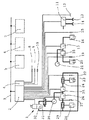
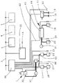
図1において、電気ブレーキ値発生器1、ブレーキ電子装置2、圧縮空気蓄積器21、30、ブレーキ圧力変調器17、18、25、26、前車軸車輪ブレーキ23、28及び後車軸車輪ブレーキ16、20は、電気制御可能な車両ブレーキ装置を形成しており、この車両ブレーキ装置は、以下において通常の省略名称“EBS”によって表わされる。EBSの構成に応じて、これにはなおセンサ、例えばブレーキ圧力センサ、車輪回転速度センサ、負荷センサ、磨耗センサが所属している。ブレーキ電子装置が1つ又は複数の車両電子装置からのデータ又は信号を、例えば負荷データを処理するEBSの構成もあり、これらのデータは、車両データバス3を介してここに供給される。このような車両電子装置は、四角形5、6、7によって記号化されている。
【0010】
EBSを装備した車両をトレーラ動作に使用できるようにする場合、なおEBSは、電気制御可能なトレーラ制御弁11、圧縮空気連結ヘッド13、14及び電気連結部12を備えている。顧客希望の装備として設けることもできるこれらの装置を介して、トレーラブレーキ装置は、従来の2導管構成様式及び/又は電気制御可能な構成において一緒に制御することができる。後者の場合、電気連結部12は、データバスインターフェースとして構成しなければならない。
【0011】
操作エネルギーとして使われる圧縮空気を車両ブレーキ装置に供給するために、車両は、周知のように構成されかつそれ故に図示していない圧力発生及び圧縮空気準備装置を装備している。
【0012】
このような車両ブレーキ装置は、ドイツ連邦共和国特許出願公開第19510933号明細書から公知であり、これについては詳細のために引用する。
【0013】
ディスクブレーキとして図に暗示した車輪ブレーキ16、20、23、28は、それぞれ所属の車軸において車両側に分配されている。
【0014】
前車軸車輪ブレーキ23、28は、EBSの障害の際に、名称“冗長弁”が一般に使われる切換え弁31により前置接続された2方向制御弁24、29を介して、ブレーキ値発生器1の吐出部分32によって操作することができる。このような緊急ブレーキ回路の詳細は、例えばドイツ連邦共和国特許出願公開第3916642号明細書(ここにおいて例えば図5において)に記載されており、これについてはこれに関連して引用する。相応して構成された緊急ブレーキ回路は、後車軸車輪ブレーキ16、20のためにも設けることができる。
【0015】
ブレーキ電子装置2に、機能“ロック防止”及び“駆動スリップ制御”が統合されており、これに対して通常の省略名称“ABS”及び“ASR”が利用される。そのため、すでにEBSのためではない場合、ブレーキ電子装置2に車輪回転速度センサ15、19、22、27から車輪回転速度信号が供給される。ASR動作において、ブレーキ電子装置2は、車両データバス3を介して機関制御電子装置5にも制御信号を送出することができる。ABS動作及びASR動作のために必要な制御弁として、ブレーキ圧力変調器17、18、25、26が使われる。
【0016】
圧縮空気蓄積器21、30、車輪ブレーキ16、20、23、28及び車輪回転速度センサ15、19、22、27は、走行運動学制御システムの構成部分でもあり、これには、さらに走行運動学電子装置4、かじ取り角センサ8、ヨー速度センサ9及び横向き加速度センサ10が所属している。車両運動学制御システムの役割は、車両の、又はトレーラ動作の存在する場合には車両列の、不安定な走行状態が生じた際に、換言すれば、ブレーキ操作以外に横滑り傾向が生じた際に、個々の又は複数の車輪ブレーキを、場合によっては及び/又はトレーラブレーキ装置を意図的に操作することによって、ヨーモーメントを発生し、これらのヨーモーメントが車両の又は車両列の運動を安定化することにある。車両データバス3を介して走行運動学電子装置4は、機関制御電子装置5にも制御信号を送出することができる。
【0017】
走行運動学制御システムの動作の詳細のため、初めに述べたヨーロッパ特許出願公開第0798615号明細書、及びATZ Automobiltechnische Zeitschrift 96 (1994) 第11巻、“Das neue Fahrsicherheitssystem Elektronic Stability Program von Mercedes−Benz”の別刷りを指摘しておく。
【0018】
図1において走行運動学電子装置4は、ブレーキ電子装置2に統合されており、かつかじ取り角センサ8、ヨー速度センサ9及び横向き加速度センサ10は、自立した構成ユニットとして設けられている。走行運動学電子装置4の統合のために、ブレーキ電子装置2は、走行運動学制御システムの特殊なセンサのために追加的な入力端子を装備している。
【0019】
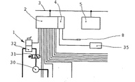
図2は、車両ブレーキ装置の一部を示しており、ここにおいてヨー速度センサ及び横向き加速度センサは、1つのセンサモジュール35にまとめられている。その際、両方のセンサは、1つの共通のハウジング内に配置することができる。センサモジュールは、例えば共通のハウジング内に、共通の電源及び場合によっては必要な保護回路を含んでいてもよい。前記のセンサのこのまとめ及びその構成は、コスト及び空間を節約する解決策をなしている。
【0020】
その他の点においてこの車両ブレーキ装置は、図1によるものに相当する。
【0021】
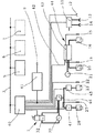
図3において、図1のブレーキ圧力変調器は、後車軸において車軸変調器44に、かつ前車軸において組合わせブレーキ圧力変調器46及びABS制御弁45、47に置き換えられている。この場合に40、43によって示すべきブレーキ電子装置は、中央モジュール40と車軸モジュール43に分割されている。
【0022】
車軸変調器44内において、車軸モジュール43と、後車軸車輪ブレーキ16、20に所属のブレーキ圧力変調器とがまとめられている。車軸モジュール43内に、ブレーキ電子装置40、43の一部が移されており、とくに後車軸車輪ブレーキ16、20に所属の部分が移されている。中央モジュール40及び車軸モジュール43は、EBSシステムバス42を介して互いに接続されている。“分散したインテリジェンス”を有するこのようなEBSは、ヨーロッパ特許出願公開第0467112号明細書に記載されており、これについては詳細のために引用する。ただしここでは車軸変調器は、個々の車輪ブレーキのための車輪変調器に分割されている。
【0023】
前車軸における組合わせブレーキ圧力変調器46は、ブレーキ電子装置40、43によって、及びブレーキ値発生器1の吐出部分32が供給する圧力によって制御することができる。このような組合わせブレーキ圧力変調器及びABS制御弁とのその共同作用は、ドイツ連邦共和国特許出願公開第4016463号明細書により公知であり、これについては詳細のために引用する。この解決策において冗長弁は、必要ない。この機能を、組合わせブレーキ圧力変調器が一緒に知覚している。
【0024】
この車両ブレーキ装置において、走行運動学電子装置41は、自立した構成ユニットとして設けられており、この構成ユニットに、ヨー速度センサ及び横向き加速度センサが統合されている。その組込み場所がその機能によって車両のかじ取り軸の範囲に確定されるかじ取り角センサ8は、走行運動学電子装置41に接続されている。他方において走行運動学電子装置41は、EBSシステムバス42に接続されており、かつこれ及びブレーキ電子装置40、43を介して車輪ブレーキに、かつその他に車両データバス3を介して機関制御電子装置5に作用する。走行運動学電子装置の車両ブレーキ装置において又はASR動作において、一方の前車軸車輪ブレーキ23又は28を操作しようとするとき、このために組合わせブレーキ圧力変調器46の制御、及び他方の前車軸車輪ブレーキ28又は23に所属のABS制御弁47又は45のその圧力維持又は圧力低下位置への切換えが必要である。
【0025】
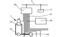
図4は、車両ブレーキ装置の一部を示しており、ここにおいてかじ取り角センサ8は、車両データバス3に接続されている。かじ取り角信号は、この場合、50によって示された走行運動学電子装置に、車両データバス3及びブレーキ電子装置40、43を介して、とくにその中央モジュールを介して供給される。通常かじ取り角センサ8は、この場合、信号準備のため及び車両データバス3を介した通信動作のための回路とともに、かじ取り角センサモジュールにまとめられている。
【0026】
その他の点において、この車両ブレーキ装置は図3によるものに相当する。
【0027】
図5においてかじ取り角センサ8は、図4におけるものとは別の方法で、EBSシステムバス42に接続されている。
【0028】
その他の点において、このブレーキ装置は図4によるものに相当する。
【0029】
図6は、車両ブレーキ装置を示しており、ここにおいて55によって示された走行運動学電子装置に、図3におけるように、ヨー速度センサ及び横向き加速度センサが統合されている。図3におけるものとは相違して、走行運動学電子装置55は、車両データバス3に接続されている。
【0030】
その他の点において、このブレーキ装置は図3によるものに相当する。
【0031】
図3、4、5及び6による構成は、ブレーキ電子装置への重要ではない介入を全く含まず又は含む走行運動学制御システムに関して、場合によっては大量生産により存在するEBSのコスト及び空間を節約する拡張を可能にする。
【0032】
車両データバス3を介して、機関制御電子装置5以外に、その他の車両電子装置にも、走行運動学制御システムのデータが供給でき、かつその逆に走行運動学制御システムが、走行安定性制御の最適化のためにその他の車両電子装置のデータ、例えばロール角を受取ることができることは、すべての実施例及び構成に当てはまる。
【0033】
前に実施例又は構成に対して行なった説明が、これらの説明から何の矛盾も生じないかぎり、別の実施例又は構成に直接又は相応した適用において一緒に成立つことは、当該技術分野の専門家には明らかである。
【0034】
本発明の保護範囲が、実施例に尽きるものではなく、その特徴が特許請求の範囲に従属するすべての構成を含むことも、当該技術分野の専門家には明らかである。
【図面の簡単な説明】
【図1】車両ブレーキ装置の略図である。
【図2】図1による装置の変形を部分的に示す図である。
【図3】別の車両ブレーキ装置の略図である。
【図4】図3による装置の変形を部分的に示す図である。
【図5】図3による装置の変形を部分的に示す図である。
【図6】別の車両ブレーキ装置の略図である。
【符号の説明】
1 ブレーキ値発生器
2 ブレーキ電子装置
3 車両データバス
4 走行運動学電子装置
5 機関制御電子装置
8 かじ取り角センサ
9 ヨー速度センサ
10 横向き加速度センサ
35 センサモジュール
40 ブレーキ電子装置
41 走行運動学電子装置
42 システムバス
43 ブレーキ電子装置
55 走行運動学電子装置[0001]
BACKGROUND OF THE INVENTION
The present invention relates to a vehicle brake device in accordance with at least a brake value signal generated from a driver by a brake electronic device and a wheel rotational speed signal, a steering angle sensor signal, a yaw speed sensor signal, and a running kinematics electronic device. The present invention relates to a vehicle brake device operated by compressed air that can be controlled according to a signal from a lateral acceleration sensor, wherein the brake electronic device is connected to at least the engine control electronic device via a vehicle data bus.
[0002]
[Prior art]
Such a vehicle braking device is known from EP-A-0798615. The brake electronics are supplied with the driver's desire to operate the brakes and the braking action required by the driver in the form of a brake value signal, and the brake electronics ensure that this meets the driver's requirements. Control the operation of the vehicle brake device. The abbreviated name “EBS” is generally used for the vehicle brake device formed in this way, and this abbreviated name is also used in the published European patent application specification.
[0003]
Often brake electronics are configured to ensure vehicle directional stability braking characteristics, uniform brake wear, and / or wheel lock prevention. In doing so, the brake electronics process another signal, for example a wheel rotation speed signal, supplied thereto from the brake system sensor, for example from a wheel rotation speed sensor and / or via the vehicle data bus. In addition, the brake electronics are configured to control the operation of the brake device for driving slip control (ASR) when the wheel rotational speed sensor signals an irregular rotational tendency in at least one driven wheel. To do is normal.
[0004]
A wheel kinematic speed signal and signals of a steering angle sensor, a yaw speed sensor, and a lateral acceleration sensor are supplied to the traveling kinematics electronic device of the vehicle brake device. According to these signals, the driving kinematics electronics monitor its lateral stability in each driving state of the vehicle, in other words: monitor its skid tendency and always keep the vehicle braking device in the optimal lateral direction of the vehicle. Control to ensure stability or so intervene in that control by the brake electronics.
[0005]
The already mentioned European patent application specification describes the physical basis and basic mode of operation of the vehicle brake device as mentioned at the outset, but the solution of the parts necessary for the realization of the brake device. It does not deal with the beginning of the measure and the possibility of the device.
[0006]
[Problems to be solved by the invention]
The object of the present invention is to provide advantageous solutions and devices for these components.
[0007]
[Means for Solving the Problems]
This problem is resolved by the inventions described in
[0008]
DETAILED DESCRIPTION OF THE INVENTION
Other advantages of the present invention are shown by the following description of the illustrated embodiment. The same reference numbers are used for parts of the same function from start to finish, and are shown using a thick line for the compressed air conduit and a thin line for the electrical control or signal lines.
[0009]
In FIG. 1, an electric
[0010]
When a vehicle equipped with EBS can be used for trailer operation, the EBS includes a
[0011]
In order to supply compressed air used as operating energy to the vehicle brake device, the vehicle is equipped with a pressure generating and compressed air preparation device which is constructed in a known manner and is therefore not shown.
[0012]
Such a vehicle braking device is known from German Offenlegungsschrift DE 19510933, which is referred to for details.
[0013]
The
[0014]
The front
[0015]
The functions “lock prevention” and “drive slip control” are integrated in the
[0016]
Compressed
[0017]
For details of the operation of the running kinematics control system, the first published European Patent Application No. 0798615, and ATZ Autobitechtechnique Zeitschrift 96 (1994),
[0018]
In FIG. 1, the traveling kinematics electronic device 4 is integrated into the brake
[0019]
FIG. 2 shows a part of the vehicle brake device, in which the yaw speed sensor and the lateral acceleration sensor are combined into one
[0020]
In other respects, the vehicle brake device corresponds to that shown in FIG.
[0021]
In FIG. 3, the brake pressure modulator of FIG. 1 is replaced by an
[0022]
In the
[0023]
The combined
[0024]
In the vehicle braking system, the running kinematics
[0025]
FIG. 4 shows a part of the vehicle brake device, in which the
[0026]
In other respects, this vehicle brake device corresponds to that according to FIG.
[0027]
In FIG. 5, the
[0028]
In other respects, the brake device corresponds to that according to FIG.
[0029]
Figure 6 shows a vehicle brake system, in the travel kinematics electronic equipment indicated by 55 here, as in FIG. 3, a yaw rate sensor and the lateral acceleration sensor is integrated. Unlike the one in FIG. 3, the travel kinematics
[0030]
In other respects, the brake device corresponds to that according to FIG.
[0031]
The configuration according to FIGS. 3, 4, 5 and 6 saves the cost and space of existing EBS, possibly due to mass production, with respect to a travel kinematic control system that does not include or include any non-critical intervention in the brake electronics. Allows expansion.
[0032]
In addition to the engine control
[0033]
It is to be understood in the art that descriptions previously given to an embodiment or configuration together hold in applications directly or corresponding to another embodiment or configuration, unless there is no contradiction from these descriptions. It is obvious to experts.
[0034]
It will be apparent to those skilled in the art that the scope of protection of the present invention is not limited to the embodiments but includes all configurations whose characteristics are dependent on the scope of the claims.
[Brief description of the drawings]
FIG. 1 is a schematic view of a vehicle brake device.
2 shows in part a variant of the device according to FIG.
FIG. 3 is a schematic view of another vehicle brake device.
4 shows in part a modification of the device according to FIG. 3;
5 shows in part a modification of the device according to FIG.
FIG. 6 is a schematic diagram of another vehicle brake device.
[Explanation of symbols]
DESCRIPTION OF
Claims (4)
ヨー速度センサ及び横向き加速度センサが、走行運動学電子装置(41)に統合され、かつ走行運動学電子装置(4)が、ブレーキ電子装置(2)に統合されていることを特徴とする、車両ブレーキ装置。The vehicle brake device is at least in accordance with a brake value signal generated from the driver by the brake electronic device (40, 43), and the wheel rotational speed signal and the steering angle sensor (8) signal by the traveling kinematics electronic device (41). The brake electronic device (40, 43) is operated by compressed air that can be controlled in accordance with the yaw speed sensor signal and the lateral acceleration sensor signal, and at least the engine control electronic device (5) via the vehicle data bus (3). In the vehicle brake device connected to
A vehicle characterized in that a yaw speed sensor and a lateral acceleration sensor are integrated into a travel kinematics electronic device (41) and a travel kinematics electronic device (4) is integrated into a brake electronic device (2). Brake device.
Applications Claiming Priority (2)
| Application Number | Priority Date | Filing Date | Title |
|---|---|---|---|
| DE19755431A DE19755431A1 (en) | 1997-12-13 | 1997-12-13 | Vehicle brake system |
| DE19755431.8 | 1997-12-13 |
Publications (2)
| Publication Number | Publication Date |
|---|---|
| JPH11278225A JPH11278225A (en) | 1999-10-12 |
| JP4632002B2 true JP4632002B2 (en) | 2011-02-16 |
Family
ID=7851784
Family Applications (1)
| Application Number | Title | Priority Date | Filing Date |
|---|---|---|---|
| JP37727698A Expired - Fee Related JP4632002B2 (en) | 1997-12-13 | 1998-12-09 | Vehicle brake device |
Country Status (4)
| Country | Link |
|---|---|
| US (1) | US6264289B1 (en) |
| EP (1) | EP0922618B1 (en) |
| JP (1) | JP4632002B2 (en) |
| DE (2) | DE19755431A1 (en) |
Families Citing this family (43)
| Publication number | Priority date | Publication date | Assignee | Title |
|---|---|---|---|---|
| DE19755431A1 (en) * | 1997-12-13 | 1999-06-17 | Wabco Gmbh | Vehicle brake system |
| DE19815440A1 (en) | 1998-04-07 | 1999-10-14 | Wabco Gmbh | Control device for a vehicle brake system |
| DE10002685A1 (en) * | 2000-01-22 | 2001-07-26 | Wabco Gmbh & Co Ohg | Method for detecting the incorrect installation of sensing devices in a vehicle |
| DE10030128A1 (en) † | 2000-06-20 | 2002-01-17 | Knorr Bremse Systeme | Stabilization of articulated trains (ESP) |
| DE10038046B4 (en) * | 2000-08-02 | 2005-11-03 | Knorr-Bremse Systeme für Nutzfahrzeuge GmbH | Stabilization device for motor vehicles with pneumatic brake devices |
| DE50105852D1 (en) * | 2000-08-22 | 2005-05-12 | Continental Teves Ag & Co Ohg | DEVICE FOR DRIVING DYNAMIC CONTROL AND METHOD FOR ORIENTATION OF DRIVING DYNAMIC SENSORS |
| DE10041206A1 (en) * | 2000-08-22 | 2002-03-07 | Continental Teves Ag & Co Ohg | Vehicle dynamics regulating device has vehicle dynamics sensor(s) integrated into regulator unit or valve block, especially mechanically attached to/enclosed by regulator unit housing |
| US7424347B2 (en) * | 2001-07-19 | 2008-09-09 | Kelsey-Hayes Company | Motion sensors integrated within an electro-hydraulic control unit |
| WO2003008244A1 (en) * | 2001-07-19 | 2003-01-30 | Kelsey-Hayes Company | Motion sensors integrated within an electro-hydraulic control unit |
| DE10146770A1 (en) * | 2001-09-22 | 2003-04-17 | Daimler Chrysler Ag | Brake system for a vehicle |
| DE10223296A1 (en) * | 2001-10-02 | 2003-04-24 | Claas Industrietechnik Gmbh | Control of agricultural vehicles, supports changes in speed and direction of gear rotation using braking system, whilst bypassing starting clutch |
| DE10203207B4 (en) * | 2002-01-21 | 2015-03-26 | Volkswagen Ag | Electromechanical brake system |
| DE10231843C5 (en) | 2002-07-12 | 2008-05-21 | Lucas Automotive Gmbh | Electronic system for a motor vehicle |
| DE10236922A1 (en) * | 2002-08-12 | 2004-03-04 | Knorr-Bremse Systeme für Nutzfahrzeuge GmbH | Pressure control module for a compressed air brake system of a vehicle |
| DE10315662A1 (en) | 2003-04-04 | 2004-10-14 | Lucas Automotive Gmbh | Method for operating a vehicle unit and electronic system for a motor vehicle |
| DE10351652B4 (en) * | 2003-11-05 | 2005-08-04 | Daimlerchrysler Ag | Control system for a vehicle |
| DE10357373B4 (en) * | 2003-12-09 | 2006-08-24 | Knorr-Bremse Systeme für Nutzfahrzeuge GmbH | Electronic brake system for a vehicle |
| ITTO20031044A1 (en) * | 2003-12-24 | 2005-06-25 | Sab Wabco Spa | BRAKING SYSTEM FOR A RAIL VEHICLE AUTOMOTOR PROVIDED WITH AN ANTI-POLLUTION. |
| DE102004018664A1 (en) * | 2004-04-13 | 2005-11-10 | Hahn-Meitner-Institut Berlin Gmbh | Method and arrangement for crystal growth from metallic melts or melting solutions |
| DE102005020626B4 (en) | 2005-05-03 | 2012-07-19 | Knorr-Bremse Systeme für Nutzfahrzeuge GmbH | Braking device of a tractor-trailer combination with stretch braking function |
| US7966113B2 (en) * | 2005-08-25 | 2011-06-21 | Robert Bosch Gmbh | Vehicle stability control system |
| US7641014B2 (en) | 2006-01-31 | 2010-01-05 | Robert Bosch Gmbh | Traction control system and method |
| DE102006018554B3 (en) * | 2006-04-21 | 2008-01-10 | Knorr-Bremse Systeme für Schienenfahrzeuge GmbH | Direct braking device of a rail vehicle with electronic control and additional pneumatic circuit |
| SE0602484L (en) * | 2006-11-22 | 2008-05-23 | Scania Cv Ab | Adaptive brake control |
| FR2914260A1 (en) * | 2007-03-27 | 2008-10-03 | Renault Sas | Four wheeled motor vehicle e.g. industrial vehicle, for e.g. building site, has electronic control unit including auxiliary units decelerating torques to be applied on wheels found at interior or exterior of turning via units, respectively |
| DE102007015995B4 (en) * | 2007-04-03 | 2015-10-08 | Zf Friedrichshafen Ag | Axle module for a vehicle |
| DE102007021646A1 (en) | 2007-05-09 | 2008-11-13 | Wabco Gmbh | modulator |
| JP4744493B2 (en) * | 2007-08-24 | 2011-08-10 | 三菱電機株式会社 | Vehicle control device |
| DE102008046957A1 (en) | 2007-10-20 | 2009-04-23 | Continental Teves Ag & Co. Ohg | Modular electronic vehicle control system |
| DE102007057043A1 (en) | 2007-11-27 | 2009-05-28 | Continental Teves Ag & Co. Ohg | Device for driving dynamics control |
| US8589049B2 (en) | 2007-12-03 | 2013-11-19 | Lockheed Martin Corporation | GPS-based system and method for controlling vehicle characteristics based on terrain |
| US8145402B2 (en) | 2007-12-05 | 2012-03-27 | Lockheed Martin Corporation | GPS-based traction control system and method using data transmitted between vehicles |
| DE102007059688A1 (en) * | 2007-12-12 | 2009-06-25 | Lucas Automotive Gmbh | Actuator device and method for driving the actuator device |
| DE102008003381B4 (en) | 2008-01-07 | 2024-10-02 | Zf Cv Systems Hannover Gmbh | braking system for a vehicle |
| US8229639B2 (en) | 2009-02-17 | 2012-07-24 | Lockheed Martin Corporation | System and method for stability control |
| US8352120B2 (en) | 2009-02-17 | 2013-01-08 | Lockheed Martin Corporation | System and method for stability control using GPS data |
| US8244442B2 (en) | 2009-02-17 | 2012-08-14 | Lockheed Martin Corporation | System and method for stability control of vehicle and trailer |
| DE102009013895B4 (en) | 2009-03-19 | 2011-06-30 | Knorr-Bremse Systeme für Nutzfahrzeuge GmbH, 80809 | Vehicle with a device for controlling the driving dynamics with steering angle sensor integrated in a common unit, yaw rate sensor and acceleration sensor |
| DE102013021681A1 (en) * | 2013-12-19 | 2015-06-25 | Wabco Gmbh | Electropneumatic brake system for a trailer |
| DE102014112015A1 (en) * | 2014-08-22 | 2016-02-25 | Knorr-Bremse Systeme für Nutzfahrzeuge GmbH | Method for controlling a operated by a service brake valve device service brake device and service brake device |
| JP6882455B2 (en) | 2016-09-08 | 2021-06-02 | クノル−ブレムゼ ジステーメ フューア ヌッツファールツォイゲ ゲゼルシャフト ミット ベシュレンクテル ハフツングKnorr−Bremse Systeme fuer Nutzfahrzeuge GmbH | Vehicle electrical system |
| FR3074040B1 (en) | 2017-11-27 | 2022-03-04 | Id Nest Medical | OPTIMIZED STRUCTURE FOR AN EXPANDABLE IMPLANT OF THE STENT OR ENDOPROSTHESIS TYPE |
| CN111301393B (en) * | 2020-03-26 | 2022-10-11 | 东风柳州汽车有限公司 | Automobile man-machine driving mode-shared braking control system and control method |
Family Cites Families (20)
| Publication number | Priority date | Publication date | Assignee | Title |
|---|---|---|---|---|
| US3683009A (en) | 1968-10-10 | 1972-08-08 | Du Pont | {60 , {62 -bis(trifluoromethyl) stilbenes |
| JPS6364858A (en) * | 1986-09-04 | 1988-03-23 | Sumitomo Electric Ind Ltd | Control device for brake pressure in vehicle |
| DE3916642A1 (en) | 1989-05-22 | 1990-11-29 | Wabco Westinghouse Fahrzeug | BRAKE CIRCUIT |
| DE4016463A1 (en) * | 1990-03-17 | 1991-09-19 | Wabco Westinghouse Fahrzeug | BRAKE SYSTEM WITH AT LEAST ONE BRAKE CIRCUIT |
| DE4022671A1 (en) * | 1990-07-17 | 1992-01-23 | Wabco Westinghouse Fahrzeug | ELECTRONIC BRAKE SYSTEM FOR ROAD VEHICLES |
| DE4228893B4 (en) * | 1992-08-29 | 2004-04-08 | Robert Bosch Gmbh | System for influencing the driving dynamics of a motor vehicle |
| JPH06219348A (en) * | 1993-01-22 | 1994-08-09 | Mazda Motor Corp | Towing vehicle and towing vehicle system |
| DE4339570B4 (en) * | 1993-11-19 | 2004-03-04 | Robert Bosch Gmbh | Electronic braking system |
| DE4436162C1 (en) * | 1994-10-10 | 1996-03-21 | Siemens Ag | System for regulating the driving stability of a motor vehicle |
| DE19510933A1 (en) | 1995-03-24 | 1996-09-26 | Wabco Gmbh | Method for determining the response pressure of a pressure-actuated brake in a vehicle brake system |
| DE19511161A1 (en) * | 1995-03-27 | 1996-10-02 | Bosch Gmbh Robert | Brake system for a motor vehicle |
| DE19512766A1 (en) * | 1995-04-05 | 1996-10-10 | Continental Ag | Vehicle ABS braking system |
| DE19521175C1 (en) * | 1995-06-10 | 1996-07-11 | Continental Ag | Electrically or electronically controlled brake system |
| JPH09226556A (en) * | 1996-02-21 | 1997-09-02 | Aisin Seiki Co Ltd | Vehicle motion control device |
| JP3257392B2 (en) * | 1996-02-23 | 2002-02-18 | トヨタ自動車株式会社 | Vehicle behavior control device |
| EP0798615B1 (en) * | 1996-02-27 | 2002-01-02 | KNORR-BREMSE SYSTEME FÜR NUTZFAHRZEUGE GmbH | Procedure for drive stability enhancement |
| DE19631856A1 (en) * | 1996-08-07 | 1998-02-12 | Bosch Gmbh Robert | Vehicle ride stability regulation method |
| DE19634567B4 (en) * | 1996-08-27 | 2007-11-29 | Robert Bosch Gmbh | Electric brake system |
| JP3288390B2 (en) * | 1997-02-19 | 2002-06-04 | シーメンス アクチエンゲゼルシヤフト | Vehicle brake system and method for data transmission in electrically controlled vehicle brake system |
| DE19755431A1 (en) * | 1997-12-13 | 1999-06-17 | Wabco Gmbh | Vehicle brake system |
-
1997
- 1997-12-13 DE DE19755431A patent/DE19755431A1/en not_active Withdrawn
-
1998
- 1998-10-07 EP EP98118970A patent/EP0922618B1/en not_active Revoked
- 1998-10-07 DE DE59813965T patent/DE59813965D1/en not_active Revoked
- 1998-12-09 JP JP37727698A patent/JP4632002B2/en not_active Expired - Fee Related
- 1998-12-09 US US09/208,298 patent/US6264289B1/en not_active Expired - Lifetime
Also Published As
| Publication number | Publication date |
|---|---|
| DE59813965D1 (en) | 2007-05-24 |
| JPH11278225A (en) | 1999-10-12 |
| US6264289B1 (en) | 2001-07-24 |
| DE19755431A1 (en) | 1999-06-17 |
| EP0922618B1 (en) | 2007-04-11 |
| EP0922618A3 (en) | 2000-08-02 |
| EP0922618A2 (en) | 1999-06-16 |
Similar Documents
| Publication | Publication Date | Title |
|---|---|---|
| JP4632002B2 (en) | Vehicle brake device | |
| JP3923093B2 (en) | Electronic brake device | |
| JP2791964B2 (en) | Electronic braking device for road vehicles | |
| JP3288493B2 (en) | Pressure control module used in compressed air brake system | |
| US5961190A (en) | Brake system for a motor vehicle | |
| US20040015281A1 (en) | Electronic control system, particularly for a vehicle brake system | |
| US8442737B2 (en) | Method for operating a vehicle brake system and vehicle brake system | |
| CN115195685B (en) | Braking systems for autonomous vehicles | |
| US20110168502A1 (en) | Combined vehicle brake system with hydraulically and electromechanically actuatable wheel brakes | |
| US20080021623A1 (en) | Redundant Brake Control System for a Vehicle | |
| US20120109470A1 (en) | Control device for the brake system of a vehicle | |
| JPH05236606A (en) | Braking system of electric automobile | |
| JP3116314B2 (en) | Vehicle with trailing axle that can be raised and lowered | |
| JP2009161175A (en) | Vehicle braking device | |
| US12097838B2 (en) | Braking system for an autonomous vehicle | |
| US8770674B2 (en) | Modulator | |
| JP2000043698A (en) | Control device for vehicle brake device | |
| JP3004861B2 (en) | Anti-skid brake control method for vehicle equipped with one-axis, one-modulator, two-wheel speed sensor | |
| EP1758778B1 (en) | Control and power supply network for vehicle braking system | |
| CA2492481C (en) | Motor vehicle having a brake system and a drive system | |
| CN112714727A (en) | Brake system for vehicle | |
| CN114194161A (en) | An electronically controlled braking system suitable for medium and heavy trucks | |
| JPH10278763A (en) | Vehicle braking method | |
| CN116872898A (en) | A commercial vehicle brake-by-wire system and method | |
| US6672683B1 (en) | Electronically regulated brake system |
Legal Events
| Date | Code | Title | Description |
|---|---|---|---|
| A621 | Written request for application examination |
Free format text: JAPANESE INTERMEDIATE CODE: A621 Effective date: 20051122 |
|
| A977 | Report on retrieval |
Free format text: JAPANESE INTERMEDIATE CODE: A971007 Effective date: 20080521 |
|
| A131 | Notification of reasons for refusal |
Free format text: JAPANESE INTERMEDIATE CODE: A131 Effective date: 20080527 |
|
| A521 | Request for written amendment filed |
Free format text: JAPANESE INTERMEDIATE CODE: A523 Effective date: 20080822 |
|
| A131 | Notification of reasons for refusal |
Free format text: JAPANESE INTERMEDIATE CODE: A131 Effective date: 20090616 |
|
| A521 | Request for written amendment filed |
Free format text: JAPANESE INTERMEDIATE CODE: A523 Effective date: 20090903 |
|
| A02 | Decision of refusal |
Free format text: JAPANESE INTERMEDIATE CODE: A02 Effective date: 20100525 |
|
| A521 | Request for written amendment filed |
Free format text: JAPANESE INTERMEDIATE CODE: A523 Effective date: 20100819 |
|
| A911 | Transfer to examiner for re-examination before appeal (zenchi) |
Free format text: JAPANESE INTERMEDIATE CODE: A911 Effective date: 20101004 |
|
| TRDD | Decision of grant or rejection written | ||
| A01 | Written decision to grant a patent or to grant a registration (utility model) |
Free format text: JAPANESE INTERMEDIATE CODE: A01 Effective date: 20101026 |
|
| A01 | Written decision to grant a patent or to grant a registration (utility model) |
Free format text: JAPANESE INTERMEDIATE CODE: A01 |
|
| A61 | First payment of annual fees (during grant procedure) |
Free format text: JAPANESE INTERMEDIATE CODE: A61 Effective date: 20101102 |
|
| R150 | Certificate of patent or registration of utility model |
Free format text: JAPANESE INTERMEDIATE CODE: R150 |
|
| FPAY | Renewal fee payment (event date is renewal date of database) |
Free format text: PAYMENT UNTIL: 20131126 Year of fee payment: 3 |
|
| R250 | Receipt of annual fees |
Free format text: JAPANESE INTERMEDIATE CODE: R250 |
|
| R250 | Receipt of annual fees |
Free format text: JAPANESE INTERMEDIATE CODE: R250 |
|
| R250 | Receipt of annual fees |
Free format text: JAPANESE INTERMEDIATE CODE: R250 |
|
| R250 | Receipt of annual fees |
Free format text: JAPANESE INTERMEDIATE CODE: R250 |
|
| LAPS | Cancellation because of no payment of annual fees |