JP4631440B2 - Vehicle and gas fuel tank mounting method - Google Patents
Vehicle and gas fuel tank mounting method Download PDFInfo
- Publication number
- JP4631440B2 JP4631440B2 JP2005002273A JP2005002273A JP4631440B2 JP 4631440 B2 JP4631440 B2 JP 4631440B2 JP 2005002273 A JP2005002273 A JP 2005002273A JP 2005002273 A JP2005002273 A JP 2005002273A JP 4631440 B2 JP4631440 B2 JP 4631440B2
- Authority
- JP
- Japan
- Prior art keywords
- gas fuel
- vehicle
- fuel tank
- hydrogen
- tank
- Prior art date
- Legal status (The legal status is an assumption and is not a legal conclusion. Google has not performed a legal analysis and makes no representation as to the accuracy of the status listed.)
- Active
Links
Images


Classifications
-
- B—PERFORMING OPERATIONS; TRANSPORTING
- B60—VEHICLES IN GENERAL
- B60K—ARRANGEMENT OR MOUNTING OF PROPULSION UNITS OR OF TRANSMISSIONS IN VEHICLES; ARRANGEMENT OR MOUNTING OF PLURAL DIVERSE PRIME-MOVERS IN VEHICLES; AUXILIARY DRIVES FOR VEHICLES; INSTRUMENTATION OR DASHBOARDS FOR VEHICLES; ARRANGEMENTS IN CONNECTION WITH COOLING, AIR INTAKE, GAS EXHAUST OR FUEL SUPPLY OF PROPULSION UNITS IN VEHICLES
- B60K15/00—Arrangement in connection with fuel supply of combustion engines or other fuel consuming energy converters, e.g. fuel cells; Mounting or construction of fuel tanks
- B60K15/03—Fuel tanks
- B60K15/063—Arrangement of tanks
- B60K15/067—Mounting of tanks
- B60K15/07—Mounting of tanks of gas tanks
-
- B—PERFORMING OPERATIONS; TRANSPORTING
- B60—VEHICLES IN GENERAL
- B60K—ARRANGEMENT OR MOUNTING OF PROPULSION UNITS OR OF TRANSMISSIONS IN VEHICLES; ARRANGEMENT OR MOUNTING OF PLURAL DIVERSE PRIME-MOVERS IN VEHICLES; AUXILIARY DRIVES FOR VEHICLES; INSTRUMENTATION OR DASHBOARDS FOR VEHICLES; ARRANGEMENTS IN CONNECTION WITH COOLING, AIR INTAKE, GAS EXHAUST OR FUEL SUPPLY OF PROPULSION UNITS IN VEHICLES
- B60K15/00—Arrangement in connection with fuel supply of combustion engines or other fuel consuming energy converters, e.g. fuel cells; Mounting or construction of fuel tanks
- B60K15/03—Fuel tanks
- B60K15/063—Arrangement of tanks
- B60K2015/0639—Arrangement of tanks the fuel tank is arranged near or in the roof
-
- B—PERFORMING OPERATIONS; TRANSPORTING
- B60—VEHICLES IN GENERAL
- B60Y—INDEXING SCHEME RELATING TO ASPECTS CROSS-CUTTING VEHICLE TECHNOLOGY
- B60Y2200/00—Type of vehicle
- B60Y2200/10—Road Vehicles
- B60Y2200/14—Trucks; Load vehicles, Busses
- B60Y2200/143—Busses
-
- B—PERFORMING OPERATIONS; TRANSPORTING
- B60—VEHICLES IN GENERAL
- B60Y—INDEXING SCHEME RELATING TO ASPECTS CROSS-CUTTING VEHICLE TECHNOLOGY
- B60Y2200/00—Type of vehicle
- B60Y2200/10—Road Vehicles
- B60Y2200/14—Trucks; Load vehicles, Busses
- B60Y2200/143—Busses
- B60Y2200/1432—Low floor busses
Landscapes
- Engineering & Computer Science (AREA)
- Life Sciences & Earth Sciences (AREA)
- Sustainable Development (AREA)
- Sustainable Energy (AREA)
- Chemical & Material Sciences (AREA)
- Combustion & Propulsion (AREA)
- Transportation (AREA)
- Mechanical Engineering (AREA)
- Cooling, Air Intake And Gas Exhaust, And Fuel Tank Arrangements In Propulsion Units (AREA)
- Body Structure For Vehicles (AREA)
- Fuel Cell (AREA)
- Filling Or Discharging Of Gas Storage Vessels (AREA)
Description
本発明は、車両およびガス燃料タンクの搭載方法に関し、詳しくは、ガス燃料を貯蔵する少なくとも一つのガス燃料タンクを搭載する車両およびガス燃料を貯蔵する少なくとも一つのガス燃料タンクを車両に搭載する搭載方法に関する。 The present invention relates to a vehicle and a method for mounting a gas fuel tank, and more particularly, to a vehicle that mounts at least one gas fuel tank that stores gas fuel and to mount at least one gas fuel tank that stores gas fuel in the vehicle. Regarding the method.
従来、この種の車両としては、長手方向の先端部の出入口に弁体が取り付けられた圧縮天然ガスを貯蔵する複数のガス燃料タンクをその長手方向が車両の前後方向となるよう車両の屋根上に搭載するバスが提案されている(例えば、特許文献1参照)。この車両では、ガス燃料タンクの長手方向を車両の前後方向とすることにより、車幅より長いガス燃料タンクを用いることができるものとしている。
しかしながら、上述の車両では、乗降口は車両の側面に設けられるのが多いため、乗降口から比較的近傍にガス燃料タンクの出入口が配置される場合も生じ、この場合、ガス燃料タンクからガス燃料が外部に放出されたときには放出されたガス燃料の乗降口への影響を小さくするのが不十分になる場合が生じる。なお、ガス燃料タンクからガス燃料が外部に放出される場合としては、弁体に異常が生じてガス燃料が漏れたときやタンク内の圧力異常に伴って弁体を開弁したときなどが想定される。 However, in the above-described vehicle, since the entrance / exit is often provided on the side surface of the vehicle, an entrance / exit of the gas fuel tank may be disposed relatively close to the entrance / exit. When the fuel is released to the outside, it may be insufficient to reduce the influence of the released gas fuel on the entrance / exit. In addition, when gas fuel is discharged from the gas fuel tank to the outside, it is assumed that the valve body has malfunctioned and gas fuel has leaked, or the valve body has been opened due to abnormal pressure in the tank. Is done.
本発明の車両およびガス燃料タンクの搭載方法は、ガス燃料タンクからガス燃料が外部に放出された際における放出されたガス燃料による乗降口における影響をより小さくすることことを目的の一つとする。また、本発明の車両およびガス燃料タンクの搭載方法は、ガス燃料タンクからガス燃料が外部に放出された際における放出されたガス燃料をより希釈することを目的の一つとする。 One object of the vehicle and the gas fuel tank mounting method of the present invention is to further reduce the influence of the discharged gas fuel on the entrance when the gas fuel is discharged from the gas fuel tank. Another object of the vehicle and the gas fuel tank mounting method of the present invention is to further dilute the gas fuel released when the gas fuel is discharged from the gas fuel tank to the outside.
本発明の車両およびガス燃料タンクの搭載方法は、上述の目的の少なくとも一部を達成するために以下の手段を採った。 The vehicle and the gas fuel tank mounting method of the present invention adopt the following means in order to achieve at least a part of the above-described object.
本発明の車両は、
ガス燃料を貯蔵する少なくとも一つのガス燃料タンクを搭載する車両であって、
前記ガス燃料タンクの長手方向が車両の左右方向になると共に該ガス燃料タンクにおけるガス燃料の出入口として該ガス燃料タンクに取り付けられた弁構造体が前記車両の乗員室の乗降口から離れるよう搭載してなる
ことを要旨とする。
The vehicle of the present invention
A vehicle equipped with at least one gas fuel tank for storing gas fuel,
The gas fuel tank is mounted so that the longitudinal direction of the gas fuel tank is the left-right direction of the vehicle, and the valve structure attached to the gas fuel tank as the gas fuel inlet / outlet of the gas fuel tank is separated from the passenger door of the passenger compartment of the vehicle This is the summary.
この本発明の車両では、ガス燃料タンクの長手方向が車両の左右方向になると共にガス燃料タンクにおけるガス燃料の出入口に取り付けられた弁構造体が車両の乗員室の乗降口から離れるように搭載するから、ガス燃料タンクに取り付けられた弁構造体からガス燃料が外部に放出されたときの放出されたガス燃料による乗降口への影響をより小さくすることができる。ここで、車両としては小型乗用車や大型乗用車、バスなどの自動車や列車などをあげることができる。 In the vehicle of the present invention, the gas fuel tank is mounted so that the longitudinal direction of the gas fuel tank is the left-right direction of the vehicle, and the valve structure attached to the gas fuel inlet / outlet of the gas fuel tank is separated from the entrance / exit of the passenger compartment of the vehicle. Thus, when the gas fuel is released from the valve structure attached to the gas fuel tank, the influence of the released gas fuel on the entrance / exit can be further reduced. Here, examples of the vehicle include a small passenger car, a large passenger car, a car such as a bus, and a train.
こうした本発明の車両において、前記乗降口と前記弁構造体とが車両の左右方向の一方
と他方となるよう前記ガス燃料タンクを搭載してなるものとすることもできる。通常、乗降口は車両の左右の側面のうちの対向車とすれ違わない側に設けられるから、ガス燃料タンクの出入口の弁構造体を対向車とすれ違う側に配置することにより、弁構造体近傍の対向車等による走行風の影響も大きくなる。したがって、弁構造体を介してガス燃料が外部に放出されたときのガス燃料の希釈を促進することができ、放出したガス燃料の乗降口への影響をより小さくすることができる。
In such a vehicle of the present invention, the gas fuel tank may be mounted so that the entrance / exit and the valve structure are one side and the other side in the left-right direction of the vehicle. Normally, the entrance / exit is provided on the side of the left and right sides of the vehicle that does not pass the oncoming vehicle, so the valve structure at the gas fuel tank entrance / exit is located on the side that passes the oncoming vehicle, so that The influence of the driving wind due to other oncoming vehicles will also increase. Therefore, dilution of the gas fuel when the gas fuel is discharged to the outside through the valve structure can be promoted, and the influence of the released gas fuel on the entrance / exit can be further reduced.
また、本発明の車両において、前記乗降口と前記弁構造体とが略車幅以上離れるよう前記ガス燃料タンクを搭載してなるものとすることもできる。こうすれば、ガス燃料タンクのガス燃料の出入口からガス燃料が外部に放出されたときの放出されたガス燃料による乗降口への影響をより小さくすることができる。 Further, in the vehicle of the present invention, the gas fuel tank may be mounted so that the entrance / exit and the valve structure are separated from each other by approximately the vehicle width. If it carries out like this, when the gaseous fuel is discharged | emitted outside from the gaseous fuel entrance / exit of a gaseous fuel tank, the influence on the entrance / exit by the released gaseous fuel can be made smaller.
さらに、本発明の車両において、前記ガス燃料タンクを前記車両の屋根上に搭載してなるものとすることもできる。こうすれば、容易にガス燃料タンクをその長手方向を車両の左右方向に搭載することができる。 Furthermore, in the vehicle according to the present invention, the gas fuel tank may be mounted on the roof of the vehicle. In this way, the gas fuel tank can be easily mounted in the left-right direction of the vehicle.
あるいは、本発明の車両において、前記弁構造体が長手方向の一方の先端部近傍に取り付けられてなるガス燃料タンクを搭載してなるものとすることもできる。こうすれば、弁構造体を乗降口からより離すことができる。 Alternatively, in the vehicle of the present invention, a gas fuel tank in which the valve structure is attached in the vicinity of one end in the longitudinal direction may be mounted. In this way, the valve structure can be further separated from the entrance / exit.
本発明の車両において、前記弁構造体は前記ガス燃料タンクの長手方向に対して略垂直方向にガス燃料を放出する安全弁を含み、前記安全弁からのガス燃料の放出方向が水平より下方向となるよう前記ガス燃料タンクを搭載してなるものとすることもできる。この場合、前記安全弁から放出されたガス燃料が車両ボディにより拡散されるよう前記ガス燃料タンクを搭載してなるものとすることもできる。こうすれば、安全弁から放出されたガス燃料の拡散性を向上させ、その希釈を図ることができる。 In the vehicle of the present invention, the valve structure includes a safety valve that discharges gas fuel in a direction substantially perpendicular to the longitudinal direction of the gas fuel tank, and the direction in which the gas fuel is discharged from the safety valve is lower than horizontal. The gas fuel tank can be mounted as described above. In this case, the gas fuel tank may be mounted so that the gas fuel discharged from the safety valve is diffused by the vehicle body. If it carries out like this, the diffusibility of the gas fuel discharge | released from the safety valve can be improved, and the dilution can be aimed at.
本発明のガス燃料タンクの搭載方法は、
ガス燃料を貯蔵する少なくとも一つのガス燃料タンクを車両に搭載する搭載方法であって、
前記ガス燃料タンクの長手方向が車両の左右方向となると共に該ガス燃料タンクにおけるガス燃料の出入口として該ガス燃料タンクに取り付けられた弁構造体が前記車両の乗員室の乗降口から離れるよう搭載する
ことを要旨とする。
The gas fuel tank mounting method of the present invention includes:
A mounting method for mounting on a vehicle at least one gas fuel tank for storing gas fuel,
The gas fuel tank is mounted so that the longitudinal direction of the gas fuel tank is the left-right direction of the vehicle, and the valve structure attached to the gas fuel tank as the gas fuel inlet / outlet of the gas fuel tank is separated from the passenger door of the vehicle passenger compartment. This is the gist.
この本発明のガス燃料タンクの搭載方法は、ガス燃料タンクの長手方向が車両の左右方向になると共にガス燃料タンクにおけるガス燃料の出入口に取り付けられた弁構造体が車両の乗員室の乗降口から離れるように搭載するから、ガス燃料タンクに取り付けられた弁構造体からガス燃料が外部に放出されたときの放出されたガス燃料による乗降口への影響をより小さくすることができる。 In the gas fuel tank mounting method of the present invention, the longitudinal direction of the gas fuel tank is the left-right direction of the vehicle, and the valve structure attached to the gas fuel inlet / outlet of the gas fuel tank is provided from the entrance / exit of the passenger compartment of the vehicle. Since it mounts so that it may leave | separate, when the gas fuel is discharge | released outside from the valve structure attached to the gas fuel tank, the influence on the entrance / exit by the released gas fuel can be made smaller.
次に、本発明を実施するための最良の形態を実施例を用いて説明する。 Next, the best mode for carrying out the present invention will be described using examples.
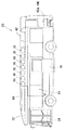
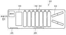
図1は本発明の一実施例としての燃料電池搭載バス20の構成の概略を示す構成図であり、図2は実施例の燃料電池搭載バス20の屋根22の上に水素タンク30を搭載している様子を説明する説明図であり、図3は燃料電池搭載バス20の後部と屋根22に燃料電池40a,40bと水素タンク30を搭載している様子を説明する説明図であり、図4は燃料電池搭載バス20の屋根22における水素タンク30の配置を説明する配置図である
。図示するように、実施例の燃料電池搭載バス20は、左側通行用として右前部に運転席が設けられ、運転席近傍の左側面に設けられた前乗降口26と中央の左側面に設けられた中央乗降口28を介して乗客室24に乗客を乗降させる大型バスとして構成されており、その最後部下部には燃料電池40a,40bが、屋根22の上にはこの燃料電池40a,40bに供給する燃料としての水素を蓄える7本の水素タンク30が搭載されている。なお、燃料電池搭載バス20の屋根22の上には、7本の水素タンク30の外に、水素タンク30の前方にはエアコンユニット60が、後方には燃料電池40a,40bを冷却する複数のラジエータ42などが搭載されており、天井部に複数の換気口52が取り付けられたルーフカバー50によって覆われている。
FIG. 1 is a block diagram showing an outline of the configuration of a fuel
水素タンク30の長手方向の一端部には、燃料電池40a,40b側に供給する水素の圧力を調整する調圧弁や高温(例えば110℃以上)になると溶けてタンク内の水素を外部に放出する安全弁としての溶栓弁などが組み込まれた弁ユニット32が取り付けられており、この弁ユニット32が燃料電池搭載バス20の右側面側となるように且つその長手方向が車両の左右方向となるように屋根22の上にベルト39により搭載されている。即ち、弁ユニット32は、前乗降口26や中央乗降口28からできるだけ離れるように、図4に例示するように、中央乗降口28に最も近くに配置される水素タンク30でも少なくとも略車幅程度以上離れるように搭載されているのである。このように弁ユニット32を前乗降口26や中央乗降口28から離すのは、弁ユニット32から水素が漏れたり弁ユニット32の溶栓弁が溶けてタンクから水素が放出されたときでも、漏れたり放出された水素の前乗降口26や中央乗降口28への影響を小さくするためである。
A pressure regulating valve for adjusting the pressure of hydrogen supplied to the
ルーフカバー50の複数の換気口52は、所定角度(例えば15度や20度)以上の直射日光が水素タンク30に当たらないように且つ雨滴が直接水素タンク30に当たらないように複数の細長板材を角度と隙間をもって重なるように構成されており、紫外線や雨滴から水素タンク30を保護している。ルーフカバー50の複数の換気口52は、ルーフカバー50の取付下部54の隙間56と共にルーフカバー50内の圧力が異常に上昇したときでもその圧力を逃がすようにその開口面積が計算されて形成されている。
The plurality of
弁ユニット32の溶栓弁の水素の放出口34は、図5に示すように、鉛直下方に向けられており、放出した水素が燃料電池搭載バス20の屋根22に当たって拡散するようになっている。したがって、緊急時に溶栓弁が溶けて水素が放出されると、放出された水素は、屋根22に当たって拡散し、ルーフカバー50の換気口52から上方に逃げていくことになる。このように水素の放出口34を鉛直下方に向けて放出された水素が燃料電池搭載バス20の屋根22に当たるようにすることにより、放出された水素の拡散を図り、その希釈化をより効果的に行なうことができる。
As shown in FIG. 5, the
以上説明した実施例の燃料電池搭載バス20によれば、水素タンク30を、その長手方向の一端部に取り付けられた弁ユニット32が前乗降口26や中央乗降口28からできるだけ離れるように且つその長手方向が車両の左右方向となるように屋根22の上に搭載することにより、弁ユニット32から水素が漏れたり弁ユニット32の溶栓弁が溶けてタンクから水素が放出されたときでも、漏れたり放出された水素の前乗降口26や中央乗降口28への影響を小さくすることができる。また、弁ユニット32の溶栓弁の水素の放出口34が鉛直下方に向くように水素タンク30を搭載することにより、溶栓弁が溶けて水素が放出されたときには放出された水素を燃料電池搭載バス20の屋根22に当てて拡散させ、水素をより希釈させることができる。これにより、溶栓弁が溶けて水素が放出されたときにおける放出された水素の前乗降口26や中央乗降口28への影響をより小さくすることができる。
According to the fuel
実施例の燃料電池搭載バス20では、左側通行用のバスとして構成したが、右側通行用
のバスとして構成してもよい。この場合、運転席や前乗降口26,中央乗降口28については右側に設け、水素タンク30についてはその長手方向の一端部に取り付けられた弁ユニット32が左側面側となるように且つその長手方向が車両の左右方向となるように屋根22に搭載すればよい。
Although the fuel cell-mounted
実施例の燃料電池搭載バス20では、水素タンク30を屋根22の上に搭載するものとしたが、水素タンク30の弁ユニット32が前乗降口26や中央乗降口28からできるだけ離れるように搭載すればよいから、水素タンク30の搭載位置は屋根22の上に限られず、乗客室の下方など、如何なる搭載位置としても構わない。
In the fuel
実施例の燃料電池搭載バス20では、水素タンク30をその長手方向が車両の左右方向となるように屋根22の上に搭載するものとしたが、水素タンク30の弁ユニット32が前乗降口26や中央乗降口28からできるだけ離れるように搭載すればよいから、水素タンク30をその長手方向が車両の左右方向とは異なる方向となるように搭載するものとしても構わない。
In the fuel
実施例の燃料電池搭載バス20では、水素タンク30の長手方向の一端部に弁ユニット32を取り付けるものとしたが、水素タンク30をその弁ユニット32が前乗降口26や中央乗降口28からできるだけ離れるように搭載すればよいから、水素タンク30の如何なる箇所に弁ユニット32を取り付けるものとしても差し支えない。
In the fuel
実施例の燃料電池搭載バス20では、水素タンク30の弁ユニット32の溶栓弁の水素の放出口34が鉛直下方に向くように水素タンク30を搭載するものとしたが、放出された水素の希釈化を図ることができればよいから、放出口34の向きは鉛直下方に限られず、水平より下方方向であっても構わない。また、放出された水素の拡散が図れればよいから、放出された水素がルーフカバー50に当たるように放出口34の方向を定めてもよい。
In the fuel
実施例では、ガス燃料タンクとしての水素タンク30を燃料電池搭載バス20に搭載する手法として説明したが、天然ガスなどの水素以外のガス燃料を貯蔵するガス燃料タンクを車両に搭載する手法に適用するものとしてもよい。
In the embodiment, the
以上、本発明を実施するための最良の形態について実施例を用いて説明したが、本発明はこうした実施例に何等限定されるものではなく、本発明の要旨を逸脱しない範囲内において、種々なる形態で実施し得ることは勿論である。 The best mode for carrying out the present invention has been described with reference to the embodiments. However, the present invention is not limited to these embodiments, and various modifications can be made without departing from the gist of the present invention. Of course, it can be implemented in the form.
本発明は、ガス燃料タンクを搭載する車両の製造産業などに利用可能である。 The present invention can be used in the manufacturing industry of vehicles equipped with gas fuel tanks.
20 燃料電池搭載バス、22 屋根、24 乗客室、26 前乗降口、28 中央乗降口、30 水素タンク、32 弁ユニット、34 放出口、39 ベルト、40a,40b 燃料電池、42 ラジエータ、50 ルーフカバー 52 換気口、54 取付下部、56 隙間、60 エアコンユニット。
20 Fuel cell mounted bus, 22 roof, 24 passenger cabin, 26 front entrance / exit, 28 center entrance / exit, 30 hydrogen tank, 32 valve unit, 34 outlet, 39 belt, 40a, 40b fuel cell, 42 radiator, 50
Claims (5)
前記ガス燃料タンクの長手方向が車両の左右方向になると共に該ガス燃料タンクにおけるガス燃料の出入口として該ガス燃料タンクに取り付けられた弁構造体と前記車両の乗員室の乗降口とが車両の左右方向の一方と他方となって離れるよう前記ガス燃料タンクを前記車両の屋根上に搭載してなり、
前記弁構造体は前記ガス燃料タンクの長手方向に対して略垂直方向にガス燃料を放出する安全弁を含み、
前記安全弁からのガス燃料の放出方向が水平より下方向となるよう前記ガス燃料タンクを搭載してなる
車両。 A vehicle equipped with at least one gas fuel tank for storing gas fuel,
The longitudinal direction of the gas fuel tank is the left-right direction of the vehicle, and the valve structure attached to the gas fuel tank as the gas fuel inlet / outlet of the gas fuel tank and the entrance / exit of the passenger compartment of the vehicle are The gas fuel tank is mounted on the roof of the vehicle so as to be separated as one of the directions and the other,
The valve structure includes a safety valve that discharges gas fuel in a direction substantially perpendicular to the longitudinal direction of the gas fuel tank;
A vehicle in which the gas fuel tank is mounted so that the direction in which the gas fuel is discharged from the safety valve is lower than horizontal .
The vehicle according to any one of claims 1 to 4 , wherein the vehicle is a bus.
Priority Applications (6)
| Application Number | Priority Date | Filing Date | Title |
|---|---|---|---|
| JP2005002273A JP4631440B2 (en) | 2005-01-07 | 2005-01-07 | Vehicle and gas fuel tank mounting method |
| CNA2006800019336A CN101102914A (en) | 2005-01-07 | 2006-01-06 | Vehicle and method for loading gaseous fuel tank |
| US11/794,095 US9260009B2 (en) | 2005-01-07 | 2006-01-06 | Vehicle and method of mounting gas fuel tank |
| DE112006000144.2T DE112006000144B4 (en) | 2005-01-07 | 2006-01-06 | vehicle |
| PCT/JP2006/300108 WO2006073193A1 (en) | 2005-01-07 | 2006-01-06 | Vehicle and method for loading gaseous fuel tank |
| BRPI0606407-8A BRPI0606407B1 (en) | 2005-01-07 | 2006-01-06 | VEHICLE AND FUEL GAS TANK ASSEMBLY METHOD |
Applications Claiming Priority (1)
| Application Number | Priority Date | Filing Date | Title |
|---|---|---|---|
| JP2005002273A JP4631440B2 (en) | 2005-01-07 | 2005-01-07 | Vehicle and gas fuel tank mounting method |
Publications (2)
| Publication Number | Publication Date |
|---|---|
| JP2006188169A JP2006188169A (en) | 2006-07-20 |
| JP4631440B2 true JP4631440B2 (en) | 2011-02-16 |
Family
ID=36647670
Family Applications (1)
| Application Number | Title | Priority Date | Filing Date |
|---|---|---|---|
| JP2005002273A Active JP4631440B2 (en) | 2005-01-07 | 2005-01-07 | Vehicle and gas fuel tank mounting method |
Country Status (6)
| Country | Link |
|---|---|
| US (1) | US9260009B2 (en) |
| JP (1) | JP4631440B2 (en) |
| CN (1) | CN101102914A (en) |
| BR (1) | BRPI0606407B1 (en) |
| DE (1) | DE112006000144B4 (en) |
| WO (1) | WO2006073193A1 (en) |
Families Citing this family (22)
| Publication number | Priority date | Publication date | Assignee | Title |
|---|---|---|---|---|
| DE102009030348A1 (en) | 2009-06-25 | 2010-12-30 | GM Global Technology Operations, Inc., Detroit | Module for a vehicle chassis comprises structural components for attaching to the module on supporting components of a vehicle chassis and integrated fuel containers for coupling with structural components to absorb collisions and/or energy |
| US9114930B2 (en) * | 2011-03-07 | 2015-08-25 | Casella Waste Systems, Inc. | Compressed natural gas vehicle apparatus and method |
| US9533569B2 (en) | 2013-06-18 | 2017-01-03 | The Heil Co. | Tailgate with structurally integrated CNG system |
| CN103770632B (en) * | 2013-12-31 | 2016-01-20 | 安徽安凯汽车股份有限公司 | A kind of air-conditioned double-layer public transport vehicle combustion gas chamber structure |
| CN103996890B (en) * | 2014-05-26 | 2016-02-10 | 唐山轨道客车有限责任公司 | For the thermal control system of tramcar |
| US9579969B2 (en) * | 2014-07-25 | 2017-02-28 | Oshkosh Corporation | Refuse vehicle having tailgate-mounted CNG tanks |
| JP6344342B2 (en) * | 2015-09-04 | 2018-06-20 | トヨタ自動車株式会社 | Fuel cell vehicle |
| JP6292205B2 (en) * | 2015-10-20 | 2018-03-14 | トヨタ自動車株式会社 | Vehicle underfloor structure |
| US10696155B2 (en) * | 2016-04-01 | 2020-06-30 | Agility Fuel Systems Llc | Vehicle fluid handling systems |
| JP6477575B2 (en) * | 2016-04-19 | 2019-03-06 | トヨタ自動車株式会社 | Arrangement structure of peripheral information detection sensor |
| JP6561974B2 (en) | 2016-11-28 | 2019-08-21 | トヨタ自動車株式会社 | vehicle |
| US10914401B2 (en) | 2017-01-10 | 2021-02-09 | The Heil Co. | Fuel monitoring system |
| DE102018000432A1 (en) | 2018-01-19 | 2018-07-12 | Daimler Ag | Vehicle with at least one tank |
| JP7095485B2 (en) * | 2018-08-21 | 2022-07-05 | トヨタ自動車株式会社 | Vehicle structure of fuel cell vehicle |
| US11207974B2 (en) | 2018-09-21 | 2021-12-28 | The Heil Co. | Multiple gas tank assembly with individual pressure monitoring |
| CN112918283B (en) * | 2019-12-05 | 2022-04-22 | 未势能源科技有限公司 | A vehicle that is used for gas bomb of vehicle and has it |
| JP7226366B2 (en) * | 2020-02-12 | 2023-02-21 | トヨタ自動車株式会社 | fuel storage device |
| JP7238827B2 (en) | 2020-02-13 | 2023-03-14 | トヨタ自動車株式会社 | fuel cell vehicle |
| JP7279686B2 (en) * | 2020-05-25 | 2023-05-23 | トヨタ自動車株式会社 | Hydrogen tank storage case |
| JP7202331B2 (en) * | 2020-07-20 | 2023-01-11 | 本田技研工業株式会社 | fuel cell car |
| DE102020211938A1 (en) | 2020-09-23 | 2022-03-24 | Ford Global Technologies, Llc | Tank arrangement for a motor vehicle |
| CN114734902B (en) * | 2022-06-10 | 2022-09-02 | 中国石油大学(华东) | Small-scale natural gas hydrate storage and transportation method and intelligent device |
Citations (2)
| Publication number | Priority date | Publication date | Assignee | Title |
|---|---|---|---|---|
| JP2000225855A (en) * | 1999-02-03 | 2000-08-15 | Nissan Diesel Motor Co Ltd | Car body structure of compressed natural gas engine- mounted bus |
| JP2001239845A (en) * | 2000-02-28 | 2001-09-04 | Mitsubishi Automob Eng Co Ltd | Fuel gas cylinder mounting structure of vehicle |
Family Cites Families (11)
| Publication number | Priority date | Publication date | Assignee | Title |
|---|---|---|---|---|
| US3213821A (en) * | 1964-03-10 | 1965-10-26 | Vincent R Godwin | Convertible hydromobile |
| US3430647A (en) * | 1966-06-10 | 1969-03-04 | Turner Corp | Safety valve for propane cylinders |
| DE3912623A1 (en) | 1989-04-18 | 1990-10-25 | Schulz & Rackow Gastechnik Gmb | GAS BOTTLE VALVE |
| US5309972A (en) * | 1991-02-25 | 1994-05-10 | Thomas Allen C | Air vent cover |
| DE19518036C1 (en) | 1995-05-17 | 1996-12-05 | Daimler Benz Ag | Device for refueling gas bottles of a gas-powered bus |
| JP3596277B2 (en) | 1998-02-27 | 2004-12-02 | 三菱ふそうトラック・バス株式会社 | vehicle |
| JP3672445B2 (en) | 1998-10-22 | 2005-07-20 | 日産ディーゼル工業株式会社 | Body structure of a bus with a compressed natural gas engine |
| JP2000170606A (en) | 1998-12-03 | 2000-06-20 | Hino Motors Ltd | Fuel gas piping structure for automobile |
| KR100325737B1 (en) | 1999-06-17 | 2002-03-06 | 류정열 | Connection Structure of Assembly Multi-line Fuel Tank of Cars Using LPG |
| US6367573B1 (en) * | 1999-09-20 | 2002-04-09 | Fab Industries, Llc | Cylinder mount for fuel system |
| JP3791383B2 (en) * | 2001-10-10 | 2006-06-28 | 日産自動車株式会社 | Fuel tank mounting structure for fuel cell vehicles |
-
2005
- 2005-01-07 JP JP2005002273A patent/JP4631440B2/en active Active
-
2006
- 2006-01-06 CN CNA2006800019336A patent/CN101102914A/en active Pending
- 2006-01-06 US US11/794,095 patent/US9260009B2/en not_active Expired - Fee Related
- 2006-01-06 BR BRPI0606407-8A patent/BRPI0606407B1/en not_active IP Right Cessation
- 2006-01-06 WO PCT/JP2006/300108 patent/WO2006073193A1/en active Application Filing
- 2006-01-06 DE DE112006000144.2T patent/DE112006000144B4/en active Active
Patent Citations (2)
| Publication number | Priority date | Publication date | Assignee | Title |
|---|---|---|---|---|
| JP2000225855A (en) * | 1999-02-03 | 2000-08-15 | Nissan Diesel Motor Co Ltd | Car body structure of compressed natural gas engine- mounted bus |
| JP2001239845A (en) * | 2000-02-28 | 2001-09-04 | Mitsubishi Automob Eng Co Ltd | Fuel gas cylinder mounting structure of vehicle |
Also Published As
| Publication number | Publication date |
|---|---|
| JP2006188169A (en) | 2006-07-20 |
| DE112006000144T5 (en) | 2008-02-21 |
| BRPI0606407A2 (en) | 2009-06-23 |
| CN101102914A (en) | 2008-01-09 |
| BRPI0606407B1 (en) | 2019-10-08 |
| DE112006000144B4 (en) | 2016-12-29 |
| US9260009B2 (en) | 2016-02-16 |
| WO2006073193A1 (en) | 2006-07-13 |
| US20080156809A1 (en) | 2008-07-03 |
Similar Documents
| Publication | Publication Date | Title |
|---|---|---|
| JP4631440B2 (en) | Vehicle and gas fuel tank mounting method | |
| JP4594107B2 (en) | Bus-type vehicle | |
| JP4158770B2 (en) | vehicle | |
| US7770679B2 (en) | Installation structure of release pipe in fuel cell vehicle and fuel gas vehicle | |
| US20080191500A1 (en) | Bumper structure of automotive vehicle | |
| WO2012053246A1 (en) | Air-cooled fuel cell vehicle | |
| CN112344206B (en) | High-pressure vessel mounting structure | |
| JP4375233B2 (en) | Vehicle equipped with gas fuel tank | |
| KR20080028602A (en) | Rear air conditioning system for a car | |
| CN109094472B (en) | Vehicle with a steering wheel | |
| US11215324B2 (en) | High pressure container unit | |
| JP2008213746A (en) | Defroster nozzle | |
| US20220285784A1 (en) | Battery arrangement, motor vehicle, and method for discharging gases from a battery | |
| KR102310208B1 (en) | A fire engine having boarding room | |
| JP4306615B2 (en) | Vehicle equipped with gas fuel tank | |
| WO2006073191A1 (en) | Vehicle | |
| JP4692594B2 (en) | Vehicle with gas fuel tank | |
| JP2022061404A (en) | Cooling device for electronic device for vehicle, control method for cooling device for electronic device for vehicle and control program for cooling device for electronic device for vehicle | |
| JP7464302B1 (en) | Installation materials | |
| JP2006137233A (en) | High-pressure fuel gas tank fixing system | |
| JP2007335292A (en) | Defogger structure of vehicular lighting fixture | |
| KR20230054529A (en) | Discharge guide device of hydrogen gas and hydrogen fueled vehicle including the same | |
| JP2024046261A (en) | Vehicle duct structure | |
| KR100613707B1 (en) | Vent-duct in a car and there of cast | |
| JP4193593B2 (en) | Vehicle front end structure |
Legal Events
| Date | Code | Title | Description |
|---|---|---|---|
| A621 | Written request for application examination |
Free format text: JAPANESE INTERMEDIATE CODE: A621 Effective date: 20070613 |
|
| A131 | Notification of reasons for refusal |
Free format text: JAPANESE INTERMEDIATE CODE: A131 Effective date: 20100622 |
|
| A521 | Request for written amendment filed |
Free format text: JAPANESE INTERMEDIATE CODE: A523 Effective date: 20100728 |
|
| TRDD | Decision of grant or rejection written | ||
| A01 | Written decision to grant a patent or to grant a registration (utility model) |
Free format text: JAPANESE INTERMEDIATE CODE: A01 Effective date: 20101019 |
|
| A01 | Written decision to grant a patent or to grant a registration (utility model) |
Free format text: JAPANESE INTERMEDIATE CODE: A01 |
|
| A61 | First payment of annual fees (during grant procedure) |
Free format text: JAPANESE INTERMEDIATE CODE: A61 Effective date: 20101101 |
|
| R151 | Written notification of patent or utility model registration |
Ref document number: 4631440 Country of ref document: JP Free format text: JAPANESE INTERMEDIATE CODE: R151 |
|
| FPAY | Renewal fee payment (event date is renewal date of database) |
Free format text: PAYMENT UNTIL: 20131126 Year of fee payment: 3 |