JP4630649B2 - camera - Google Patents
camera Download PDFInfo
- Publication number
- JP4630649B2 JP4630649B2 JP2004339107A JP2004339107A JP4630649B2 JP 4630649 B2 JP4630649 B2 JP 4630649B2 JP 2004339107 A JP2004339107 A JP 2004339107A JP 2004339107 A JP2004339107 A JP 2004339107A JP 4630649 B2 JP4630649 B2 JP 4630649B2
- Authority
- JP
- Japan
- Prior art keywords
- lens
- focus
- camera
- driving
- drive
- Prior art date
- Legal status (The legal status is an assumption and is not a legal conclusion. Google has not performed a legal analysis and makes no representation as to the accuracy of the status listed.)
- Expired - Fee Related
Links
Images


Landscapes
- Focusing (AREA)
- Automatic Focus Adjustment (AREA)
- Studio Devices (AREA)
Description
本発明は、撮影レンズ装置を着脱可能なカメラに関し、特にカメラ側に焦点(合焦位置)検出機能を有し撮影レンズ装置側にレンズ駆動制御手段を有し、これらのカメラと撮影レンズ装置とを通信可能に接続可能なカメラに関する。 The present invention relates to a camera to which a photographic lens device can be attached and detached, and in particular, has a focus (focus position) detection function on the camera side and has lens drive control means on the photographic lens device side. The present invention relates to a camera that can be connected to communicate with each other.
自動焦点調節機能(AFシステム)のための焦点調節状態の検出方式として、位相差検出方式とコンラスト検出方式がある。
位相差検出方式によるAFシステムは、概略以下のように動作する。
すなわち、撮影レンズから入射した光は、撮影光軸に対して45度の傾きで配置された半透過メインミラーの背面に取り付けられたサブミラーによって、カメラ下方に反射され、2次光学系のレンズによって2つの像に分離されて、一対のAFセンサに入射する。これら一対のAFセンサは横並びに配置されており、これら一対のAFセンサ上に形成される2像の間隔の差によって、合焦状態、前ピン状態および後ピン状態を判定する。そして、この像間隔が合焦状態の間隔になるように焦点調節レンズ(フォーカスレンズ)を移動させてピント合わせをする。つまり、2像のずれ量と像面移動量(デフォーカス量)との関係は光学系によって決まっているので、そのずれ量からデフォーカス量を求める。そしてこのデフォーカス量とレンズ固有情報(敏感度係数、開放FNo等)からレンズの繰り出し量を求め、焦点調節レンズを移動させて合焦を得る。
As a detection method of the focus adjustment state for the automatic focus adjustment function (AF system), there are a phase difference detection method and a contrast detection method.
The AF system based on the phase difference detection system generally operates as follows.
That is, the light incident from the photographing lens is reflected downward by the sub-mirror attached to the back of the semi-transmissive main mirror disposed at an inclination of 45 degrees with respect to the photographing optical axis, and is reflected by the lens of the secondary optical system. It is separated into two images and enters a pair of AF sensors. The pair of AF sensors are arranged side by side, and the in-focus state, the front pin state, and the rear pin state are determined based on the difference between the two images formed on the pair of AF sensors. Then, focusing is performed by moving the focus adjustment lens (focus lens) so that the image interval becomes the in-focus interval. That is, since the relationship between the shift amount of the two images and the image plane movement amount (defocus amount) is determined by the optical system, the defocus amount is obtained from the shift amount. Then, a lens extension amount is obtained from the defocus amount and lens specific information (sensitivity coefficient, open FNo, etc.), and the focus adjustment lens is moved to obtain in-focus.
一方、コントラスト検出方式の一種として摂動法(ウォブリング法)があり、この摂動法によるAFシステムは概略以下のように動作する。
このAFシステムは、2次元の撮像素子を含む撮像系と、演算部およびレンズの制御信号を発生する信号発生部を含むシステムコントロール部と、光軸方向にレンズを移動させるためのレンズ制御部を含むレンズ部とから構成される。まず、撮像系において画像光を取り込み、それを撮像信号として出力させ、システムコントロール部へ送り、そこで撮像信号に含まれる高周波成分を抽出する。そして、この抽出信号の最大値を記憶しておいて、焦点調節レンズをある方向に移動させ、同じように画像光を取り込み、高周波成分抽出を行う。このとき、抽出信号の最大値が先に記憶された値よりも大きい場合は、焦点調節レンズの移動方向が合焦面に近づいているものとして、今回の値を記憶し直して、焦点調節レンズを同じ方向に移動させる。また、今回の抽出信号の最大値が前回のものより小さい場合は、焦点調節レンズの移動方向が合焦面から遠ざかっているものとして、今回の値を記憶し直して、焦点調節レンズを前回とは反対方向に移動させ、同じように画像光を取り込み、高周波成分を抽出して最大値比較を行い、最終的に合焦面に像面をもっていく。ここでは1度だけレンズを移動させ、移動前後での抽出信号の最大値を比較することでレンズ移動方向を決定することを説明したが、実際にはデータの信頼性を上げるため前述の動作を複数回繰り返しレンズ移動方向を決定する。
On the other hand, there is a perturbation method (a wobbling method) as one type of contrast detection method, and an AF system based on this perturbation method generally operates as follows.
The AF system includes an image pickup system including a two-dimensional image pickup device, a system control unit including a signal generation unit that generates a control signal for the arithmetic unit and the lens, and a lens control unit for moving the lens in the optical axis direction. And a lens part including. First, image light is captured in the imaging system, output as an imaging signal, sent to the system control unit, and a high-frequency component included in the imaging signal is extracted there. Then, the maximum value of the extracted signal is stored, the focus adjustment lens is moved in a certain direction, image light is taken in the same way, and high frequency component extraction is performed. At this time, if the maximum value of the extracted signal is larger than the previously stored value, it is assumed that the moving direction of the focus adjustment lens is approaching the in-focus plane, the current value is stored again, and the focus adjustment lens Are moved in the same direction. Also, if the maximum value of the current extraction signal is smaller than the previous value, it is assumed that the moving direction of the focus adjustment lens is moving away from the in-focus plane, the current value is stored again, and the focus adjustment lens is Is moved in the opposite direction, and the image light is taken in the same way, high frequency components are extracted and the maximum values are compared, and finally the image plane is brought to the focal plane. Here, it has been explained that the lens movement direction is determined by moving the lens only once and comparing the maximum value of the extracted signal before and after the movement. However, in order to increase the reliability of the data, the above operation is actually performed. The lens moving direction is determined repeatedly several times.
銀塩フィルムに画像を写す一眼レフタイプのカメラとして、自動焦点調節機能(AFシステム)を有し、カメラに対して交換可能な撮影レンズからなる一眼レフタイプのカメラが多用されているが、この一眼レフタイプのカメラにおいては、撮影レンズの焦点調節状態の検出方式としてAF時間を重視し位相差検出方式を用いることが多い。 As a single-lens reflex type camera that captures an image on a silver salt film, a single-lens reflex type camera that has an automatic focusing function (AF system) and includes a photographing lens that can be exchanged for the camera is widely used. In a single-lens reflex camera, a phase difference detection method is often used as a detection method of a focus adjustment state of a photographing lens with an emphasis on AF time.
以下に位相差検出方式を用いた一眼レフタイプのカメラの構成例を説明する。
カメラは、レンズとの通信を行うための通信部、レンズを通って入射する光の量を測定する測光部、位相差検出方式により被写体までの距離(デフォーカス量)を測定するための測距部、フィルムを適当な時間露光するためのシャッター制御部、フィルムの巻き上げ・巻き戻しを行うフィルム給送部、レリーズ操作のためのレリーズSW、およびこれらの制御および検出を行う制御部からなる。また、レンズはカメラとの通信を行う通信部、フォーカスレンズを駆動するレンズ駆動部、絞りを駆動する絞り駆動部、およびこれらの制御を行う制御部からなる。
A configuration example of a single-lens reflex type camera using a phase difference detection method will be described below.
The camera has a communication unit for communicating with the lens, a photometric unit for measuring the amount of light incident through the lens, and a distance measuring unit for measuring the distance (defocus amount) to the subject by the phase difference detection method. A shutter control unit for exposing the film for an appropriate time, a film feeding unit for winding and rewinding the film, a release SW for the release operation, and a control unit for controlling and detecting them. The lens includes a communication unit that communicates with the camera, a lens driving unit that drives the focus lens, an aperture driving unit that drives the aperture, and a control unit that controls these.
オートフォーカス機能設定での撮影は、以下のシーケンスにより動作する。撮影者がレリーズSW操作をすることによりカメラは測光・測距を行い、その結果から絞りの駆動量、および前述の如くフォーカスレンズの駆動量を演算し、各駆動命令および駆動量をレンズへ送信する。レンズは受信した駆動量だけ絞りおよびフォーカスレンズを駆動する。その後カメラはシャッターを制御しフィルムを適当な時間露光する。 Shooting with the autofocus function setting operates according to the following sequence. When the photographer operates the release SW, the camera performs photometry and distance measurement. From the result, the drive amount of the diaphragm and the drive amount of the focus lens are calculated as described above, and each drive command and drive amount are transmitted to the lens. To do. The lens drives the aperture and focus lens by the received drive amount. The camera then controls the shutter to expose the film for an appropriate time.
ところがAFシステムの課題として、AF精度の向上とAF時間の短縮がある。またカメラのデジタル化に伴い以下の理由でさらなるAF精度の向上が必要である。
デジタルカメラでは、銀塩フィルムと撮像素子の大きさ(面積)の違いにより、AFセンサの1画素に相当する撮像面の割合が大きくなる、つまり検出画素が粗くなって、精度が下がるという問題が生じる。この問題を解消するためには、AF光学系の倍率を下げたり、AFセンサの画素ピッチを小さくしたり等すればよいが、システム構成上、精度的に厳しく、またコストもかかってしまう。
However, the AF system has problems in improving AF accuracy and shortening AF time. Further, with the digitalization of cameras, further improvement of AF accuracy is necessary for the following reasons.
In the digital camera, the ratio of the imaging surface corresponding to one pixel of the AF sensor increases due to the difference in the size (area) of the silver salt film and the imaging device, that is, the detection pixel becomes rough and the accuracy decreases. Arise. In order to solve this problem, the magnification of the AF optical system may be decreased, or the pixel pitch of the AF sensor may be reduced. However, the system configuration is strictly accurate and costs high.
このため、デジタルカメラでは、コントラスト検出方式によるAFシステムがしばしば用いられる。
以下にコントラスト検出方式AFを有し、レンズ側にレンズ駆動制御手段を有し通信可能に接続したカメラの動作シーケンスについて図4を用いて説明する。
[ステップ101]カメラのメインスイッチがONされることにより本シーケンスが開始される。
[ステップ102]カメラ本体に設けられたレリーズスイッチがON状態になったかどうかを判断する。ONならばステップ103へ、OFFならば待機する。
For this reason, in a digital camera, an AF system based on a contrast detection method is often used.
An operation sequence of a camera having a contrast detection AF and having a lens drive control unit on the lens side and connected to be communicable will be described below with reference to FIG.
[Step 101] This sequence is started by turning on the main switch of the camera.
[Step 102] It is determined whether or not a release switch provided in the camera body is turned on. If ON, go to Step 103, and if OFF, wait.
[ステップ103]各フォーカスレンズ位置において撮像信号から高周波成分を抽出する回数をカウントするカウンターを0に初期化する。
[ステップ104]撮像素子から出力された撮像信号を取り込み、取り込んだ撮像信号から高周波成分を抽出し、抽出した高周波成分のデータをメモリバッファに一時保存する。
[ステップ105]カメラはレンズへ通信回路を介しフォーカシングレンズを所定方向に所定駆動量だけ駆動する旨の通信を行い、レンズは受信した方向に受信した駆動量だけフォーカシングレンズを駆動する。
[Step 103] A counter that counts the number of times a high-frequency component is extracted from the imaging signal at each focus lens position is initialized to zero.
[Step 104] The image pickup signal output from the image pickup device is taken in, a high frequency component is extracted from the taken image pickup signal, and the extracted high frequency component data is temporarily stored in a memory buffer.
[Step 105] The camera communicates with the lens via the communication circuit to drive the focusing lens in a predetermined direction by a predetermined drive amount, and the lens drives the focusing lens by the received drive amount in the received direction.
[ステップ106]撮像素子から出力された撮像信号を取り込み、取り込んだ撮像信号から高周波成分を抽出し、抽出した高周波成分のデータをメモリバッファに一時保存する。
[ステップ107]カウンターを1インクリメントする。
[ステップ108]カウンター値が3であればステップ110へ移行し、3未満であれば109へ移行する。
[ステップ109]カメラはレンズへ通信回路を介しフォーカシングレンズをステップ105で設定した方向と逆の方向に所定駆動量だけ駆動する旨の通信を行い、レンズは受信した方向に受信した駆動量だけフォーカシングレンズを駆動する。その後ステップ104へ移行する。
[Step 106] The image pickup signal output from the image pickup device is taken in, a high frequency component is extracted from the taken image pickup signal, and the extracted high frequency component data is temporarily stored in a memory buffer.
[Step 107] The counter is incremented by one.
[Step 108] If the counter value is 3, go to
[Step 109] The camera communicates to the lens via the communication circuit that the focusing lens is driven by a predetermined drive amount in the direction opposite to the direction set in
[ステップ110]ステップ104、ステップ106で保存した高周波成分のデータから合焦判定を行う。合焦と判定した場合ステップ111へ移行し、非合焦と判定した場合レンズの駆動方向を決定しステップ103移行して上記動作を再度行う。
[ステップ111]カメラはシャッターを制御しフィルムを適当な時間露光し撮影を完了する。
図5は、前述のシーケンスステップ103〜ステップ109におけるカメラとレンズの通信、およびフォーカシングレンズ位置を示すものである。
[Step 111] The camera controls the shutter, exposes the film for an appropriate time, and completes photographing.
FIG. 5 shows the communication between the camera and the lens and the focusing lens position in the sequence steps 103 to 109 described above.
前述のとおりカメラ側に焦点検出機能を有し、レンズ側にレンズ駆動制御手段を有し、かつカメラとレンズを通信可能に接続したカメラシステムにおいて、焦点検出機能をコントラスト検出方式(ウォブリング法)によるものとした場合には、フォーカスレンズの正転駆動・反転駆動を頻繁に繰り返さなければならないため、正転駆動・反転駆動の旨の通信を頻繁に行わなければならず、焦点検出動作の際の通信量が多くなる。このため高性能なCPUを搭載しない限りカメラおよびレンズの制御部はこの間に他の制御を行うことが困難となってしまう。 As described above, in the camera system having the focus detection function on the camera side, the lens drive control means on the lens side, and the camera and the lens connected to be communicable, the focus detection function is based on a contrast detection method (wobbling method). If this is the case, the forward rotation and reversal drive of the focus lens must be repeated frequently, so communication to indicate normal rotation and reversal drive must be performed frequently, and during focus detection operations. Increased communication volume. For this reason, unless a high-performance CPU is installed, it becomes difficult for the control unit of the camera and the lens to perform other controls during this period.
本発明は、上記事情に基づいてなされたものであり、カメラ側にコントラスト検出方式(ウォブリング法)による焦点検出機能を有し、レンズ側にレンズ駆動制御手段を有し、カメラとレンズを通信可能に接続したカメラシステムにおいて、焦点検出動作の際の通信量を削減し他の機能制御を支障無く行うことを課題とするものである。 The present invention has been made based on the above circumstances, has a focus detection function based on a contrast detection method (wobbling method) on the camera side, has lens drive control means on the lens side, and can communicate between the camera and the lens. It is an object of the present invention to reduce the amount of communication during the focus detection operation and perform other function control without hindrance in the camera system connected to.
上記課題を解決するために、本発明では、焦点調節レンズと前記焦点調節レンズを駆動する手段とを有する撮影レンズ装置と、前記撮影レンズに対して着脱可能で且つ通信可能に接続され、撮像手段と前記撮像手段により得られる撮像信号から抽出した高周波成分に応じて合焦位置を検出する焦点検出手段とを有するカメラ本体と、を含むカメラシステムにおいて、前記カメラ本体は、前記焦点調節レンズのウォブリング駆動の駆動量および駆動回数に関する情報を前記撮影レンズ装置に送信した後、前記情報に基づき前記焦点調節レンズのウォブリング駆動を開始する旨を前記撮影レンズ装置に送信し、前記撮影レンズ装置は、前記情報に基づき、前記焦点調節レンズのウォブリング駆動を開始する旨を受信完了したタイミングから前記焦点調節レンズのウォブリング駆動を開始し、前記カメラ本体は、前記焦点調節レンズのウォブリング駆動を停止する旨の送信を行わず、更に前記焦点調節レンズが停止したタイミング毎に前記撮像手段の出力から高周波成分を抽出し、前記抽出された高周波成分が所定値よりも小さい場合は前記駆動量を多く設定し、前記所定値よりも大きい場合は小さく設定することを特徴とする。 In order to solve the above problems, in the present invention, an imaging lens device having a focus adjustment lens and a means for driving the focus adjustment lens, and an image pickup means that is detachably and communicably connected to the shooting lens. And a camera body having a focus detection means for detecting a focus position according to a high frequency component extracted from an imaging signal obtained by the imaging means, wherein the camera body is a wobbling of the focus adjustment lens. after the information about the driving amounts and the driving frequency of the drive transmitted to the photographic lens unit, and transmits the instruction to start the wobbling drive of the focusing lens based on the information on the photographic lens unit, the imaging lens system, based on the information, the focus from the timing of receiving completed instruction to start the wobbling drive of the focus adjusting lens Starts wobbling drive of the adjusting lens, the camera body, the high-frequency components from the output of the wobbling drive of the focusing lens does not transmit the effect of stopping, the imaging unit further every timing at which the focusing lens is stopped When the extracted high frequency component is smaller than a predetermined value, the driving amount is set to be larger, and when the extracted high frequency component is larger than the predetermined value, the driving amount is set to be smaller .
焦点調節レンズのウォブリング駆動に関する情報は、例えば、駆動周期および駆動量である。 The information regarding the wobbling driving of the focus adjustment lens is, for example, a driving cycle and a driving amount.
カメラ本体は、焦点調節レンズのウォブリング駆動を停止する旨を送信することが好ましい。但し、例えば焦点調節レンズのウォブリング駆動に関する情報に駆動回数を含む場合、合焦位置検出のための焦点調節レンズのウォブリング駆動を停止する旨の送信は省略することができる。 It is preferable that the camera body transmits a message to stop wobbling driving of the focus adjustment lens. However, for example, when the number of times of driving is included in the information related to the wobbling driving of the focus adjustment lens, transmission to stop the wobbling driving of the focusing lens for detecting the in-focus position can be omitted.
本発明によれば、カメラがレンズへ駆動(ウォブリング駆動)に関するデータ(例えばフォーカスレンズ駆動量、および駆動・停止の周期)を送信した後、駆動開始命令を送信することにより、レンズが受信したデータをもとにフォーカスレンズの駆動を行う構成とすることにより、焦点検出動作の際の通信量を削減し他の機能制御を支障無く行うことができる。 According to the present invention, after the camera transmits data related to driving (wobbling driving) (for example, the focus lens driving amount and the driving / stopping cycle), the data received by the lens is transmitted by transmitting a driving start command. By adopting a configuration that drives the focus lens based on the above, it is possible to reduce the amount of communication during the focus detection operation and perform other function control without any trouble.
本発明の好ましい第1の実施の形態では、焦点調節レンズを含む撮影光学系を有した撮影レンズ装置の着脱交換が可能で、互いに通信可能に接続されたカメラであり、前記撮影光学系を通して撮像する撮像手段と、前記焦点調節レンズの各停止状態にて前記撮像手段により得られる撮像信号から抽出した高周波成分の比較による焦点調節状態の判別結果に応じて前記焦点調節レンズを合焦位置に移動させる焦点調節動作を行う制御手段とを有するカメラにおいて、前記焦点調節レンズの駆動に関する情報(駆動周期、駆動量)をカメラから撮影レンズ装置に送信した後、前記駆動に関する情報に基づいた焦点調節レンズの駆動を開始・停止する旨の通信をカメラから撮影レンズ装置に行うことにより、焦点検出動作の際の通信量を削減し他の機能制御を支障無く行うことができることを可能とする。 In a first preferred embodiment of the present invention, a photographic lens apparatus having a photographic optical system including a focus adjustment lens can be attached and detached, and the cameras are connected so as to communicate with each other, and imaging is performed through the photographic optical system. The focus adjustment lens is moved to the in-focus position according to the result of determination of the focus adjustment state by comparing the high-frequency component extracted from the image pickup signal obtained by the image pickup means in each stop state of the focus adjustment lens. A focus adjustment lens based on the information on the drive after transmitting information (drive period, drive amount) about the drive of the focus adjustment lens from the camera to the photographing lens device. By communicating from the camera to the photographic lens device to start / stop driving, the amount of communication during the focus detection operation can be reduced. It makes it possible it is possible to perform the function control without any trouble.
また、本発明の好ましい第2の実施の形態では、前記焦点調節レンズを所定駆動量だけ駆動するのに要する時間データ、もしくは所定時間内に駆動可能な駆動量データを、予め撮影レンズ装置からカメラに送信し、カメラは前記時間データ、もしくは駆動量データに基づき前記焦点調節レンズの駆動に関する情報(駆動周期、駆動量)を決定し、決定した前記焦点調節レンズの駆動に関する情報(駆動周期、駆動量)をカメラから撮影レンズ装置に送信した後、前記駆動に関する情報に基づいた焦点調節レンズの駆動を開始・停止する旨の通信をカメラから撮影レンズ装置に行うことにより、焦点検出動作の際の通信量を削減し他の機能制御を支障無く行うことができることを可能とし、更に撮影レンズ装置の能力を最大限に有効に活用することが可能となる。 In the second preferred embodiment of the present invention, time data required to drive the focus adjustment lens by a predetermined driving amount, or driving amount data that can be driven within a predetermined time is previously acquired from the photographing lens device to the camera. The camera determines information (driving period, driving amount) related to the driving of the focusing lens based on the time data or driving amount data, and determines information related to driving the determined focusing lens (driving period, driving). ) Is transmitted from the camera to the photographing lens device, and then communication is performed from the camera to the photographing lens device to start / stop the driving of the focus adjustment lens based on the information related to the driving. It is possible to reduce the amount of communication and control other functions without hindrance, and to make the best use of the capabilities of the taking lens device. Theft is possible.
以下、上記第1の実施の形態を実施例に基づいて説明する。
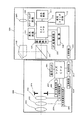
図1には、本発明の一実施例に係るデジタルカメラと撮影レンズ装置とから構成されるカメラシステムの構成を示している。図1において、100はカメラ本体であり、200はカメラ本体100に着脱可能な交換型撮影レンズ装置(以下、撮影レンズという)である。
撮影レンズ200内には、第1レンズ群201と、ズームレンズ群202と、フォーカスレンズ群203と、絞り204とが設けられている。
また、カメラ本体100内には、固定ハーフミラー内蔵のプリズム101が設けられている。被写体からの光束は、上記レンズ群201〜203および絞り204を通過して撮影光束としてカメラ本体100内のプリズム101に入射する。
Hereinafter, the first embodiment will be described based on examples.
FIG. 1 shows a configuration of a camera system including a digital camera and a photographing lens device according to an embodiment of the present invention. In FIG. 1,
In the photographing
A
撮影レンズ200内において、205は絞り駆動回路であり、レンズCPU207からの信号に応じて絞り204の開口径を制御する。206は操作スイッチであり、ズーミング、フォーカシング、絞りのマニュアル操作スイッチおよびフォーカスのオート/マニュアル切り換えの設定スイッチ等が設けられている。207はレンズCPUであり、レンズ通信回路211およびカメラ通信回路102を介してカメラCPU(制御手段)110との情報のやり取りを行うとともに、撮影レンズ200内の制御全体を司っている。208はフォーカス駆動回路であり、モータおよびその駆動回路で構成され、フォーカスレンズ群203の光軸方向の駆動をレンズCPU207からの信号に応じて行う。209は焦点距離検出回路であり、ズームレンズ群202の位置を検出することで焦点距離を検出する。なお、本実施例では、ズームレンズの位置を32分割のグレーコードパターンで検出する。210は記憶回路であり、ROMを有して構成されている。この記憶回路210には、撮影レンズ200のID(製品型番やシリアルナンバー等)、焦点距離情報、焦点距離毎のフォーカスレンズ群203の移動量に対する像面変位量の比であるフォーカス敏感度等が格納されており、レンズCPU207によって随時読み出される。
In the photographing
次に、カメラ本体100内において、プリズム101の固定ハーフミラーを透過した撮影光束は、CCDやCMOS等の撮像素子107の撮像面に結像する。なお、プリズム101の固定ハーフミラーでは、撮影光量の一部(例えば、1/3)が上方に分岐してペンタプリズム103に入射する。ペンタプリズム103を通過した光束はファインダー光学系105を通過して光学ファインダー像として撮影者に視認される。また、撮像素子107では、入射した光を光電変換して電気信号を出力する。この出力信号は、増幅されてデジタル映像信号(撮像信号)としてカメラCPU110に出力される。カメラCPU110は、この映像信号を用いて、動画像もしくは静止画像を形成する。また、デジタル化された映像信号は、カメラCPU110への出力とは別に、焦点検出手段としてのAF処理回路108に対しても出力される。
Next, in the camera
AF処理回路108においては、デジタル映像信号の一画面分の画像データに含まれる高周波成分がハイパスフィルタ(HPF)等を介して抽出され、これに対して累積加算の演算処理等が行なわれる。これによって高域側の輪郭成分量等に対応するAF評価値が算出され、いわゆるコントラスト検出方式による撮影レンズ200の焦点調節状態の検出(以下、合焦位置検出という)を可能とする。そして、このAF評価値はカメラCPU110に出力される。このように、カメラ本体100においては、コントラスト検出方式で撮影レンズ200の合焦位置検出を行う。
In the
カメラ本体100内において、104は測光回路であり、測光情報をカメラCPU110へと伝達する。106は2段スイッチを有し、1段目スイッチのオンにより測光、合焦位置検出および焦点調節動作を開始させる信号(SW1信号)を出力し、2段目スイッチのオンにより撮像素子107による撮像(露光)開始を開始させる信号(SW2信号)をカメラCPU110に出力するレリーズスイッチ回路である。
In the camera
また、カメラPU110は、上述したレンズCPU207との通信のほかに、撮像素子107により撮影された映像や設定された撮影条件および撮影モード等を表示する表示回路111の制御や、各種撮影条件および撮影モード等を設定する設定スイッチ回路112からの入力に対する制御や、電源109の残容量チェックや電力の分担等、様々なカメラ本体側の制御を担っている。また、映像信号のメモリや各種バッファメモリ等もカメラCPU110内に含まれている。
In addition to the communication with the
次に、上記カメラにて採用されているコントラスト検出方式AFでのカメラCPU110の動作シーケンスについて図2を用いて説明する。
[ステップ201]不図示のカメラのメインスイッチがONされることにより本シーケンスが開始される。
[ステップ202]カメラCPU110は、カメラ本体100に設けられたレリーズスイッチ回路106のスイッチが半押しされてSW1がON状態になったかどうかを判断する。ONならばステップ203へ、OFFならば待機する。
[ステップ203]カメラCPU110はレンズへ通信回路を介しフォーカスレンズ(焦点調節レンズ)を駆動する方向、駆動量、および駆動・停止の周期を送信する。
Next, an operation sequence of the
[Step 201] This sequence is started by turning on a main switch of a camera (not shown).
[Step 202] The
[Step 203] The
[ステップ204]各フォーカスレンズ位置において撮像信号から高周波成分を抽出する回数をカウントするカウンターを0に初期化する。
[ステップ205]カメラCPU110は通信回路102、211を介しレンズCPU207へウォブリング駆動開始命令(駆動を開始する旨)を送信し、レンズは受信したタイミングからステップ203で受信したデータをもとにフォーカスレンズの駆動を開始する。
[ステップ206]カメラCPU110はレンズの停止したタイミング毎に、撮像素子から出力された撮像信号を取り込み、取り込んだ撮像信号から高周波成分を抽出し、抽出した高周波成分のデータをメモリバッファに一時保存し、カウンターを1インクリメントする。
[ステップ207]カウンター値が6であればステップ208へ移行し、6未満であれば206へ移行する。
[Step 204] A counter that counts the number of times of extracting a high-frequency component from the imaging signal at each focus lens position is initialized to zero.
[Step 205] The
[Step 206] The
[Step 207] If the counter value is 6, go to
[ステップ208]カメラCPU110は通信回路102、211を介しレンズCPU207へウォブリング駆動停止命令(駆動を停止する旨)を送信し、レンズはフォーカスレンズの駆動を停止する。
[ステップ209]ステップ206で保存した高周波成分のデータから合焦判定を行う。合焦と判定した場合ステップ209へ移行し、非合焦と判定した場合レンズの駆動方向を決定しステップ203移行し再度動作を行う。
[ステップ210]カメラはシャッターを制御しフィルムを適当な時間露光し撮影を完了する。
[Step 208] The
[Step 209] Focus determination is performed from the high-frequency component data stored in
[Step 210] The camera controls the shutter, exposes the film for an appropriate time, and completes photographing.
図3は、前述のシーケンスステップ203〜ステップ208におけるカメラとレンズの通信、およびフォーカシングレンズ位置を示すものである。図5に示した従来のシーケンスにおけるカメラとレンズの通信と比較して分かるように、本発明により通信量を減少することが出来る。
すなわち、従来は、駆動および停止の1周期ごとにカメラ側から駆動命令および駆動量をレンズへ送信していたのに対し、本実施例では、図3に示すように、1回の焦点検出動作において、駆動および停止を何回行おうが、ウォブリング駆動に関する情報、ウォブリング駆動開始命令およびウォブリング駆動停止命令の送信は、各1回で足りる。
FIG. 3 shows the communication between the camera and the lens and the focusing lens position in the sequence steps 203 to 208 described above. As can be seen from the comparison between the camera and lens communication in the conventional sequence shown in FIG. 5, the amount of communication can be reduced by the present invention.
That is, in the prior art, a drive command and a drive amount are transmitted from the camera side to the lens for each drive and stop cycle. In this embodiment, as shown in FIG. 3, a single focus detection operation is performed. In this case, no matter how many times driving and stopping are performed, transmission of the information relating to the wobbling driving, the wobbling driving start command, and the wobbling driving stop command is sufficient once.
本実施例によれば、カメラがレンズへウォブリング駆動に関するデータ(フォーカスレンズ駆動量、および駆動・停止の周期)を送信した後、ウォブリング駆動開始命令を送信することにより、レンズが受信したデータをもとにフォーカスレンズのウォブリング駆動を行う構成とすることにより、焦点検出動作の際の通信量を削減し他の機能制御を支障無く行うことができる。 According to the present embodiment, after the camera transmits data related to wobbling driving (focus lens driving amount and driving / stopping period) to the lens, the wobbling driving start command is transmitted, so that the lens receives the data. In addition, by adopting a configuration in which the wobbling drive of the focus lens is performed, it is possible to reduce the amount of communication during the focus detection operation and perform other function control without any trouble.
[実施例の変形例]
なお、上記の実施例ではウォブリング駆動開始通信によりレンズがフォーカスレンズのウォブリング駆動を開始した後、カメラCPUが撮像信号から高周波成分を抽出する回数をカウントし所望のカウント値となった時点でウォブリング駆動停止通信を行いレンズがフォーカスレンズのウォブリング駆動を停止するものとしたが、他のウォブリング駆動に関する通信(フォーカスレンズを駆動する方向と駆動量、および駆動・停止の周期)と共に予めウォブリング回数(駆動回数)を送信し、レンズが受信したウォブリング回数を駆動した後に駆動を停止するようにしてウォブリング駆動停止命令通信を削除しても良い。即ち、フォーカスレンズの駆動に関する情報に駆動回数を含む場合は、合焦位置検出のためのフォーカスレンズの駆動を停止する旨の送信を省略することができる。
[Modification of the embodiment]
In the above embodiment, after the lens starts wobbling driving of the focus lens by the wobbling driving start communication, the number of times that the camera CPU extracts a high frequency component from the imaging signal is counted, and when the desired count value is reached, the wobbling driving is performed. The stop communication is performed and the lens stops the wobbling drive of the focus lens. However, the wobbling number of times (the number of times of driving ) is preliminarily stored together with other wobbling driving communication (direction and amount of driving of the focus lens, and driving / stopping period). ) And the driving is stopped after the number of wobbling times received by the lens is driven, and the wobbling driving stop command communication may be deleted. That is, when the number of times of driving is included in the information related to the driving of the focus lens, it is possible to omit transmission of stopping the driving of the focus lens for detecting the in-focus position.
また、駆動量の決定方法については、例えば、高周波成分データの値が小さい時は合焦から遠い位置にあるものとして駆動量を多くし、高周波成分データの値が大きい時は合焦近傍にあるものとして駆動量を小さくすると良い。
また、レンズのフォーカスレンズ駆動能力データ(所定時間内に駆動可能な駆動量、所定駆動量を駆動するに要する時間等)を予めレンズからカメラへ送信し、そのデータに基づきカメラがウォブリング駆動に関するデータ(フォーカスレンズ駆動量、および駆動・停止の周期)を決定することにより、レンズの能力を最大限に有効に活用することが出来るようにしても良い。
As for the method for determining the drive amount, for example, when the value of the high frequency component data is small, the drive amount is increased as if it is far from the focus, and when the value of the high frequency component data is large, the drive amount is near the focus. As a matter of course, the driving amount should be reduced.
In addition, the lens focus lens drive capability data (drive amount that can be driven within a predetermined time, time required to drive the predetermined drive amount, etc.) is transmitted from the lens to the camera in advance, and the camera relates to wobbling drive based on the data. By determining (focus lens driving amount and driving / stopping cycle), the lens capability may be utilized to the maximum extent.
100:カメラ
107:撮像素子
108:AF処理回路
110:カメラCPU
200:レンズ
207:レンズCPU
100: Camera 107: Image sensor 108: AF processing circuit 110: Camera CPU
200: Lens 207: Lens CPU
Claims (1)
前記カメラ本体は、前記焦点調節レンズのウォブリング駆動の駆動量および駆動回数に関する情報を前記撮影レンズ装置に送信した後、前記情報に基づき前記焦点調節レンズのウォブリング駆動を開始する旨を前記撮影レンズ装置に送信し、
前記撮影レンズ装置は、前記情報に基づき、前記焦点調節レンズのウォブリング駆動を開始する旨を受信完了したタイミングから前記焦点調節レンズのウォブリング駆動を開始し、
前記カメラ本体は、前記焦点調節レンズのウォブリング駆動を停止する旨の送信を行わず、更に前記焦点調節レンズが停止したタイミング毎に前記撮像手段の出力から高周波成分を抽出し、前記抽出された高周波成分が所定値よりも小さい場合は前記駆動量を多く設定し、前記所定値よりも大きい場合は小さく設定することを特徴とするカメラシステム。 An imaging lens device having a focus adjustment lens and a means for driving the focus adjustment lens, and connected to the photography lens so as to be detachable and communicable, and extracted from an imaging signal obtained by the imaging means and the imaging means In a camera system including a camera body having a focus detection unit that detects a focus position according to a high-frequency component,
Said camera body, said after the information relating to the driving amounts and the driving frequency of the wobbling drive of the focusing lens transmitted to the photographic lens unit, the imaging lens to the effect that starts wobbling drive of the focus adjusting lens on the basis of the information To the device,
The imaging lens device, based on said information, to start the wobbling drive of the focus adjusting lens from the timing of receiving completed instruction to start the wobbling drive of the focusing lens,
The camera body does not transmit that the wobbling drive of the focus adjustment lens is stopped, and further extracts a high frequency component from the output of the imaging means at each timing when the focus adjustment lens is stopped, and the extracted high frequency The camera system is characterized in that when the component is smaller than a predetermined value, the drive amount is set to be large, and when the component is larger than the predetermined value , the camera system is set to be small .
Priority Applications (1)
| Application Number | Priority Date | Filing Date | Title |
|---|---|---|---|
| JP2004339107A JP4630649B2 (en) | 2004-11-24 | 2004-11-24 | camera |
Applications Claiming Priority (1)
| Application Number | Priority Date | Filing Date | Title |
|---|---|---|---|
| JP2004339107A JP4630649B2 (en) | 2004-11-24 | 2004-11-24 | camera |
Publications (3)
| Publication Number | Publication Date |
|---|---|
| JP2006146062A JP2006146062A (en) | 2006-06-08 |
| JP2006146062A5 JP2006146062A5 (en) | 2008-01-17 |
| JP4630649B2 true JP4630649B2 (en) | 2011-02-09 |
Family
ID=36625812
Family Applications (1)
| Application Number | Title | Priority Date | Filing Date |
|---|---|---|---|
| JP2004339107A Expired - Fee Related JP4630649B2 (en) | 2004-11-24 | 2004-11-24 | camera |
Country Status (1)
| Country | Link |
|---|---|
| JP (1) | JP4630649B2 (en) |
Families Citing this family (12)
| Publication number | Priority date | Publication date | Assignee | Title |
|---|---|---|---|---|
| JP2007334143A (en) * | 2006-06-16 | 2007-12-27 | Olympus Imaging Corp | Interchangeable lens digital camera |
| US8208057B2 (en) * | 2008-03-27 | 2012-06-26 | Panasonic Corporation | Imaging system, camera body and interchangeable lens |
| JP5480515B2 (en) | 2008-03-28 | 2014-04-23 | パナソニック株式会社 | Camera system |
| US8311407B2 (en) * | 2008-03-28 | 2012-11-13 | Panasonic Corporation | Camera system, camera body, and interchangeable lens |
| JP4594450B2 (en) | 2008-04-17 | 2010-12-08 | パナソニック株式会社 | Interchangeable lens, camera body, camera system |
| WO2009139186A1 (en) * | 2008-05-16 | 2009-11-19 | パナソニック株式会社 | Camera system |
| US8126322B2 (en) * | 2009-03-13 | 2012-02-28 | Panasonic Corporation | Interchangeable lens, camera body, and camera system |
| JP5254904B2 (en) | 2009-08-20 | 2013-08-07 | キヤノン株式会社 | Imaging apparatus and method |
| JP5679718B2 (en) * | 2010-07-20 | 2015-03-04 | キヤノン株式会社 | Imaging device |
| JP6504969B2 (en) | 2015-08-19 | 2019-04-24 | キヤノン株式会社 | Imaging system, imaging apparatus, lens apparatus, control method of imaging system |
| JP2017151477A (en) * | 2017-05-25 | 2017-08-31 | 株式会社ニコン | Lens barrel and camera system |
| JP6803941B2 (en) * | 2019-03-28 | 2020-12-23 | キヤノン株式会社 | Imaging system, imaging device, lens device, control method of imaging system |
Citations (11)
| Publication number | Priority date | Publication date | Assignee | Title |
|---|---|---|---|---|
| JPH0289014A (en) * | 1988-09-26 | 1990-03-29 | Canon Inc | Camera device |
| JPH04273230A (en) * | 1991-02-28 | 1992-09-29 | Canon Inc | Interchangeable lens type camera system |
| JPH07248446A (en) * | 1994-03-11 | 1995-09-26 | Hitachi Ltd | Automatic focusing device |
| JPH10215401A (en) * | 1997-01-30 | 1998-08-11 | Sony Corp | Auto-focus device for video camera |
| JP2003015016A (en) * | 2001-04-24 | 2003-01-15 | Canon Inc | Optical equipment |
| JP2003015018A (en) * | 2001-07-02 | 2003-01-15 | Canon Inc | Camera, lens unit and camera system |
| JP2003029135A (en) * | 2001-07-17 | 2003-01-29 | Canon Inc | Camera, camera system and photographic lens device |
| JP2003084191A (en) * | 2001-09-11 | 2003-03-19 | Canon Inc | Camera, camera system and interchangeable lens device |
| JP2003295047A (en) * | 2002-04-05 | 2003-10-15 | Canon Inc | Image pickup device and image pickup system |
| JP2004184939A (en) * | 2002-12-06 | 2004-07-02 | Canon Inc | Camera system |
| JP2005221798A (en) * | 2004-02-06 | 2005-08-18 | Fujinon Corp | Automatic focusing system |
-
2004
- 2004-11-24 JP JP2004339107A patent/JP4630649B2/en not_active Expired - Fee Related
Patent Citations (11)
| Publication number | Priority date | Publication date | Assignee | Title |
|---|---|---|---|---|
| JPH0289014A (en) * | 1988-09-26 | 1990-03-29 | Canon Inc | Camera device |
| JPH04273230A (en) * | 1991-02-28 | 1992-09-29 | Canon Inc | Interchangeable lens type camera system |
| JPH07248446A (en) * | 1994-03-11 | 1995-09-26 | Hitachi Ltd | Automatic focusing device |
| JPH10215401A (en) * | 1997-01-30 | 1998-08-11 | Sony Corp | Auto-focus device for video camera |
| JP2003015016A (en) * | 2001-04-24 | 2003-01-15 | Canon Inc | Optical equipment |
| JP2003015018A (en) * | 2001-07-02 | 2003-01-15 | Canon Inc | Camera, lens unit and camera system |
| JP2003029135A (en) * | 2001-07-17 | 2003-01-29 | Canon Inc | Camera, camera system and photographic lens device |
| JP2003084191A (en) * | 2001-09-11 | 2003-03-19 | Canon Inc | Camera, camera system and interchangeable lens device |
| JP2003295047A (en) * | 2002-04-05 | 2003-10-15 | Canon Inc | Image pickup device and image pickup system |
| JP2004184939A (en) * | 2002-12-06 | 2004-07-02 | Canon Inc | Camera system |
| JP2005221798A (en) * | 2004-02-06 | 2005-08-18 | Fujinon Corp | Automatic focusing system |
Also Published As
| Publication number | Publication date |
|---|---|
| JP2006146062A (en) | 2006-06-08 |
Similar Documents
| Publication | Publication Date | Title |
|---|---|---|
| US6999684B2 (en) | Camera system and camera | |
| JP5942444B2 (en) | Digital camera | |
| JP4390286B2 (en) | Camera, control method thereof, program, and storage medium | |
| US20070230937A1 (en) | Digital camera | |
| US20090102960A1 (en) | Image pickup apparatus | |
| JP2003029135A (en) | Camera, camera system and photographic lens device | |
| JP4630649B2 (en) | camera | |
| JP2009229927A (en) | Autofocus adjustment device and imaging apparatus | |
| JP2008203428A (en) | Imaging apparatus | |
| JP4992761B2 (en) | LENS DRIVE DEVICE AND IMAGING DEVICE | |
| JP2010145887A (en) | Camera system | |
| JP2010145495A (en) | Camera system | |
| JP4060953B2 (en) | Electronic camera | |
| JP2010136097A (en) | Camera apparatus and camera system | |
| JP2010147612A (en) | Camera and camera system | |
| JP2008298956A (en) | Imaging apparatus | |
| JP2921868B2 (en) | Camera exposure control device | |
| JPH10142685A (en) | Silver salt photographic and electronic image pickup camera | |
| JP2644252B2 (en) | Auto focus camera | |
| JP4744253B2 (en) | Auto focus camera | |
| JP4946311B2 (en) | Focus adjustment device, camera | |
| JP2757396B2 (en) | camera | |
| JP2007240566A (en) | Focus detecting device, optical apparatus and camera | |
| JP2007011021A (en) | Electronic camera and camera system | |
| JP3216423B2 (en) | Camera ranging device |
Legal Events
| Date | Code | Title | Description |
|---|---|---|---|
| A521 | Request for written amendment filed |
Free format text: JAPANESE INTERMEDIATE CODE: A523 Effective date: 20071122 |
|
| A621 | Written request for application examination |
Free format text: JAPANESE INTERMEDIATE CODE: A621 Effective date: 20071122 |
|
| RD01 | Notification of change of attorney |
Free format text: JAPANESE INTERMEDIATE CODE: A7421 Effective date: 20090406 |
|
| RD04 | Notification of resignation of power of attorney |
Free format text: JAPANESE INTERMEDIATE CODE: A7424 Effective date: 20100201 |
|
| A131 | Notification of reasons for refusal |
Free format text: JAPANESE INTERMEDIATE CODE: A131 Effective date: 20100406 |
|
| A521 | Request for written amendment filed |
Free format text: JAPANESE INTERMEDIATE CODE: A523 Effective date: 20100528 |
|
| RD01 | Notification of change of attorney |
Free format text: JAPANESE INTERMEDIATE CODE: A7421 Effective date: 20100630 |
|
| A131 | Notification of reasons for refusal |
Free format text: JAPANESE INTERMEDIATE CODE: A131 Effective date: 20100720 |
|
| A521 | Request for written amendment filed |
Free format text: JAPANESE INTERMEDIATE CODE: A523 Effective date: 20100915 |
|
| TRDD | Decision of grant or rejection written | ||
| A01 | Written decision to grant a patent or to grant a registration (utility model) |
Free format text: JAPANESE INTERMEDIATE CODE: A01 Effective date: 20101109 |
|
| A01 | Written decision to grant a patent or to grant a registration (utility model) |
Free format text: JAPANESE INTERMEDIATE CODE: A01 |
|
| A61 | First payment of annual fees (during grant procedure) |
Free format text: JAPANESE INTERMEDIATE CODE: A61 Effective date: 20101115 |
|
| FPAY | Renewal fee payment (event date is renewal date of database) |
Free format text: PAYMENT UNTIL: 20131119 Year of fee payment: 3 |
|
| R150 | Certificate of patent or registration of utility model |
Ref document number: 4630649 Country of ref document: JP Free format text: JAPANESE INTERMEDIATE CODE: R150 Free format text: JAPANESE INTERMEDIATE CODE: R150 |
|
| LAPS | Cancellation because of no payment of annual fees |