JP4629246B2 - Tire running state detection method, tire running state detection device, road surface state estimation method, and road surface state estimation device - Google Patents
Tire running state detection method, tire running state detection device, road surface state estimation method, and road surface state estimation device Download PDFInfo
- Publication number
- JP4629246B2 JP4629246B2 JP2001036048A JP2001036048A JP4629246B2 JP 4629246 B2 JP4629246 B2 JP 4629246B2 JP 2001036048 A JP2001036048 A JP 2001036048A JP 2001036048 A JP2001036048 A JP 2001036048A JP 4629246 B2 JP4629246 B2 JP 4629246B2
- Authority
- JP
- Japan
- Prior art keywords
- tire
- pressure
- road surface
- frequency
- detecting
- Prior art date
- Legal status (The legal status is an assumption and is not a legal conclusion. Google has not performed a legal analysis and makes no representation as to the accuracy of the status listed.)
- Expired - Fee Related
Links
Images


Classifications
-
- B—PERFORMING OPERATIONS; TRANSPORTING
- B60—VEHICLES IN GENERAL
- B60C—VEHICLE TYRES; TYRE INFLATION; TYRE CHANGING; CONNECTING VALVES TO INFLATABLE ELASTIC BODIES IN GENERAL; DEVICES OR ARRANGEMENTS RELATED TO TYRES
- B60C23/00—Devices for measuring, signalling, controlling, or distributing tyre pressure or temperature, specially adapted for mounting on vehicles; Arrangement of tyre inflating devices on vehicles, e.g. of pumps or of tanks; Tyre cooling arrangements
- B60C23/02—Signalling devices actuated by tyre pressure
- B60C23/04—Signalling devices actuated by tyre pressure mounted on the wheel or tyre
- B60C23/0408—Signalling devices actuated by tyre pressure mounted on the wheel or tyre transmitting the signals by non-mechanical means from the wheel or tyre to a vehicle body mounted receiver
- B60C23/0474—Measurement control, e.g. setting measurement rate or calibrating of sensors; Further processing of measured values, e.g. filtering, compensating or slope monitoring
- B60C23/0477—Evaluating waveform of pressure readings
Landscapes
- Engineering & Computer Science (AREA)
- Mechanical Engineering (AREA)
- Tires In General (AREA)
- Control Of Driving Devices And Active Controlling Of Vehicle (AREA)
Description
【0001】
【発明の属する技術分野】
本発明は、タイヤの走行状態を検出する方法とその装置、及び、走行時の路面状態を推定する方法とその装置とに関するものである。
【0002】
【従来の技術】
自動車の走行安定性を高めるため、タイヤと路面との間の摩擦係数(路面摩擦係数)あるいは路面状態を精度良く推定し、車両制御へフィードバックすることが求められている。予め路面摩擦係数や路面状態を推定することができれば、制駆動や操舵といった危険回避の操作を起こす前に、例えば、ABSブレーキのより高度な制御等が可能になり、安全性が一段と高まることが予想される。また、運転者に走行中の路面状態の危険度を伝えるだけでも、運転者が早めの減速動作を行えるようになり、事故の減少が期待できる。
従来、路面状態を推定する方法としては、車両下部、例えばタイヤを軸支する車軸の近傍などに配設された、タイヤと路面との接触音を検出するセンサによって検出した上記接触音に基づいて路面状態を推定する方法(特開平8−261993号公報、特開平9−54020号公報)などが提案されている。
【0003】
【発明が解決しようとする課題】
しかしながら、上記のような、車体側からタイヤと路面との接触音を検出する方法では、車両が雨の中や水溜まりなどのある濡れた路面上を走行する場合も多いため、検出に用いているセンサが水に濡れて故障したりする恐れがあるだけでなく、上記センサが周囲を走行している他の車のタイヤ接触音も拾ってしまうため、当該車両のタイヤの接触音を精度よく検出することが困難であるなどの問題点があるため、実用化には到っていなかった。
【0004】
本発明は、従来の問題点に鑑みてなされたもので、路面状態やタイヤの異常の有無などのタイヤの走行状態を精度よく検出する方法とその装置を提供することを目的とする。
【0005】
【課題を解決するための手段】
本発明は、路面状態やタイヤの状態によって変化するタイヤ振動がタイヤ内部の空気に伝播され、上記空気の圧力変動として検出されるという原理を利用したもので、タイヤが接している路面の状態やタイヤの異常の有無などの複数の物理現象が、上記空気の圧力変動の異なる周波数帯に現れることに着目してなされたものである。すなわち、本発明は、現在、自転車,2輪車,乗用車から大型トラック,建設車両用タイヤに至るまで幅広く用いられている空気入りタイヤに封入されている空気の圧力変動を検出して、上記検出された圧力変動を周波数解析し、上述した、異なる周波数帯域に現れる、路面状態やタイヤの異常の有無などに起因する圧力変動の変化を検出することにより、タイヤの走行状態を検出するもので、外部と遮断されているタイヤ内の空気を利用するため、上記従来例のように、水に濡れたり周囲を走行する他の車両の影響を受けることなく、タイヤの走行状態を精度よく検出することが可能となる。
【0006】
【課題を解決するための手段】
本発明の請求項1に記載のタイヤ走行状態の検出方法は、車両のタイヤ内の空気圧の変動を検出して周波数分析し、複数の周波数帯域における上記空気圧の圧力変動値を比較して、路面状態やタイヤの異常の有無を含むタイヤの走行状態を検出するようにしたことを特徴とするものである。
また、請求項2に記載のタイヤ走行状態検出装置は、タイヤあるいはホイールに取り付けられた、タイヤ内の空気圧を検出する圧力検出手段と、上記検出された空気圧の時間変動を周波数分析して、800Hz以上の周波数帯域における上記空気圧の圧力変動値の平均値を算出する手段と、上記算出された圧力変動値の平均値から、走行中のタイヤが滑り易い状態にあるか否かを検出する走行状態検出手段とを備え、上記検出された空気圧の時間変動からタイヤの走行状態を検出するようにしたものである。
請求項3に記載のタイヤ走行状態検出装置は、40Hz,80Hz及び130Hz付近にピークを持つタイヤ固有振動がタイヤ空気圧にほぼ比例することを利用したもので、上記圧力検出手段で検出された空気圧の時間変動を周波数分析して、200Hz以下の周波数帯域における上記空気圧の圧力変動値のピーク周波数を検出し、上記検出された圧力変動値のピーク周波数から、走行中のタイヤ内の空気圧を検出するタイヤ圧監視手段を設けたものである。これにより、適用した圧力センサが空気圧の絶対値を検出できないタイプのものであっても、空気圧を検出することが可能となる。
請求項4に記載のタイヤ走行状態検出装置は、上記圧力検出手段で検出された空気圧の時間変動を周波数分析して、100Hz以下の周波数帯域における上記空気圧の圧力変動値の平均値を算出し、上記算出された圧力変動値の平均値が予め設定された基準値を超えた場合には、走行中のタイヤにトレッド剥離による異常があると判定するタイヤ異常検出手段を設けたものである。トレッド部の一部に剥離が生じた場合には、その部分が路面に接する度に振動が発生してタイヤ内面の空気を加振する。したがって、上記振動をタイヤ空気圧の圧力変動として検出することで、上記タイヤの故障を検出することが可能となる。
請求項5に記載のタイヤ走行状態検出装置は、上記圧力検出手段を、半導体式または圧電式の圧力センサ、あるいは、半導体式または圧電式のマイクロホンから構成したものである。
請求項6に記載のタイヤ走行状態検出装置は、タイヤの走行状態を更に精度よく検出するため、車速検出手段により検出された車速に応じて、上記算出された各周波数帯域での圧力変動値を比較するようにしたものである。
【0009】
ところで、転動中のタイヤは常に振動しているが、路面の滑りやすさによって路面に接しているトレッド部分の拘束状態が変化し、これが800Hz〜5000Hzといった高周波帯域での振動の差となって現れる。この振動の大きさを、路面の滑りやすさの影響の少ない周波数帯域の振動と比較することで路面状態を更に正確に推定することが可能となる。
【0010】
本発明の請求項7に記載の路面状態の推定方法は、タイヤ内の空気圧の変動を検出し、上記空気圧の少なくとも2つの周波数帯域における圧力変動値を算出し、上記算出された圧力変動値の比から、タイヤが接地している路面状態を推定するようにしたことを特徴とする。
請求項8に記載の路面状態推定装置は、タイヤあるいはホイールに取り付けられた、タイヤ内の空気圧を検出する圧力検出手段と、上記検出された空気圧の時間変動を周波数分析して、少なくとも2つの周波数帯域内での圧力変動の平均値を算出する手段と、上記算出された各周波数帯域での圧力変動の平均値の比から、路面状態を推定する路面状態推定手段とを備え、タイヤが接地している路面状態を推定するようにしたものである。
請求項9に記載の路面状態推定装置は、上記圧力検出手段を、半導体式または圧電式の圧力センサ、あるいは半導体式または圧電式のマイクロホンから構成したものである。
請求項10に記載の路面状態推定装置は、車速検出手段を備え、上記圧力変動の平均値の比と検出された車速とから路面状態を推定するようにしたものである。
【0011】
また、請求項11に記載の路面状態推定装置は、上記周波数帯域のうち、1つの周波数帯域を、路面からタイヤへの入力を特徴づける帯域である300Hz〜1200Hzに設定し、もう1つの周波数帯域を、路面の滑り易さを特徴づける帯域である800Hz〜5000Hzに設定するとともに、上記低周波側の圧力変動の平均値に対する上記高周波側の圧力変動の平均値の比が、予め設定された基準値を超えた場合には、路面が滑り易い状態にあると推定する路面状態推定手段を設けたものである。上記300Hz〜1200Hz帯域における振動は路面の滑り易さの影響を受けにくいため、800Hz〜5000Hz帯域値から路面の滑り易さ以外の外乱要因を分離する手段として、上記300Hz〜1200Hz帯域値との比を取ることで、路面の滑り易さを正確に推定することが可能となる。
請求項12に記載の路面状態推定装置は、予め、様々な路面状態及び速度で車両を走行させて、そのときの車両の制動距離と上記圧力変動の平均値の比とを計測し、上記制動距離から求めた路面摩擦係数と、上記計測された圧力変動の平均値の比とから上記基準値を算出するようにしたものである。
【0012】
【発明の実施の形態】
以下、本発明の実施の形態について、図面に基づき説明する。
実施の形態1.
図1は、本実施の形態1に係わるタイヤ走行状態検出装置10の構成を示すブロック図である。同図において、11はタイヤ内の空気圧を検出する圧力センサ、12は車輪の速度を検出する回転センサ12aの出力パルスから算出されたタイヤ回転数に基づいて車速を検出する車速検出手段、13は上記圧力センサの出力レベルの時間軸上における変動成分を周波数解析して複数の周波数帯域における圧力変動の平均値を演算する圧力変動値演算手段、14はマップ記憶手段15Mに予め記憶されたタイヤ圧の変動レベルと周波数との関係を示すマップを用いて、圧力変動値演算手段13で演算された800Hz以上の周波数帯域の圧力変動平均値からタイヤの走行状態を検出する走行状態検出手段15と、200Hz以下の周波数帯域における圧力変動のピークの周波数からタイヤ空気圧を検出するとともに、上記空気圧を用いて走行中のタイヤ圧を監視するタイヤ圧監視手段16と、100Hz以下の周波数帯域内で、タイヤ回転速度に応じて変化する圧力変動の平均値からタイヤ異常の有無を検出するタイヤ異常検出手段17とを備えたタイヤ走行状態検出手段である。
また、18は走行状態検出手段15で検出された走行状態、タイヤ圧監視手段16で検出されたタイヤ圧、タイヤ異常検出手段17で検出されたタイヤ異常の有無とに基づいて、タイヤ走行状態に異常あるいは危険がある場合には乗員に警告するタイヤ走行状態警告手段であり、このタイヤ走行状態警告手段18は、車両の走行状態がハイドロプレーニング発生や凍結路面など危険な状態であることを警告する走行状態警告手段18Aと、タイヤ圧の低下を警告するタイヤ圧低下警告手段18Bと、タイヤ異常を警告するタイヤ異常警告手段18Cとから構成される。
【0013】
本実施の形態1では、タイヤ内の空気圧を検出する圧力センサ11は、例えば、図2(a),(b)に示すように、タイヤホイール1のリム部2の図示しないタイヤ側に取付けた。なお、圧力センサ11は、タイヤのサイドトレッド部など、タイヤ本体に取付けるようにしてもよい。
上記圧力センサ11は、高周波の圧力変動を検出できる精度を有していれば、圧電式、半導体式など様々な形式を用いることができる。また、一般にマイクロフォンと呼ばれるものも空気の圧力振動を検出するセンサであり、これを圧力センサとして用いることができる。
【0014】
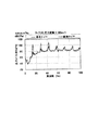
図3は、走行中のタイヤ内の圧力変動を上記圧力センサ11により検出したタイヤ内圧力変動データの一例を示す図である。このタイヤ内圧力変動データは、車両にそれぞれ新品と摩耗品のタイヤを装着した2種類の車両を、乾燥路と、水深10mmのウエット路との2種類の路面において走行速度90km/hrで走行させ、Δt=160msのサンプリングタイムで3秒間測定して周波数軸上で平均したものである。また、図4は、検証のため、タイヤトレッドの内面側に振動センサを取付けて、上記タイヤ内圧力変動と同時に測定した、走行中のトレッド振動のデータである。
よく知られているように、水深の深いウエット路を高速で走行するとハイドロプレーニングが発生し、自動車は操縦不能な非常に危険な状態に陥る。特に、摩耗したタイヤではハイドロプレーニングが発生しやすく危険である。
図4に示す測定結果から、ハイドロプレーニングが発生しタイヤが滑り易い状態では、800Hz以上の高周波領域でのトレッド振動が大幅に増大し、特に、ハイドロプレーニングが発生しやすい摩耗したタイヤでは、上記振動が大きいことがわかる。
一方、図3に示すタイヤ内圧力の変動値も、上記図4と同様の結果を示すことから、上記トレッド振動がタイヤ内の空気にも伝播し、同じ周波数帯域の圧力変動として捉えることが可能であることがわかる。これにより、路面状態やタイヤの状態によって変化するタイヤ振動をタイヤ内部の空気の圧力変動として検出することができることが確認された。
したがって、走行状態検出手段15において、圧力変動値演算手段13により演算された、上記圧力センサ11で検出されたタイヤ内の空気圧の800Hz以上の周波数帯域の圧力変動平均値を比較することで、走行状態が、ハイドロプレーニングが発生しタイヤが滑り易い状態であるかどうかを検出することが可能となる。すなわち、マップ記憶手段15Mに、上記実験結果から得られたタイヤ圧の変動レベルと周波数との関係をマップとして予め記憶させておき、上記マップを用いて、800Hz以上の周波数帯域の圧力変動平均値を上記マップの乾燥路あるいはウエット路でのデータと比較することで、タイヤが滑り易い状態であるかどうかを検出する。
【0015】
走行状態がハイドロプレーニングが発生しやすい状態である場合には、走行状態検出手段15はその情報をタイヤ走行状態警告手段18の走行状態警告手段18Aに送り、走行状態が危険な状態であることを乗員に警告する。
なお、上記実験結果から、ハイドロプレーニングが発生しやすい状態となる800Hz以上の高周波領域における圧力変動平均値の閾値を設定して、圧力センサ11から得られたタイヤ圧の圧力変動平均値を上記閾値と比較することで、タイヤが滑り易い状態であるかどうかを検出するようにしてもよい。
また、上記走行実験を様々な車速で行い、車速毎のマップあるいは閾値を用いてタイヤが滑り易い状態であるかどうかを検出するようにすれば、ハイドロプレーニングが発生しやすい状態を更に正確に判定することができる。
【0016】
また、本例では、タイヤ圧監視手段16により、圧力変動値演算手段13で演算された100Hz以下の周波数帯域内での圧力変動のピーク周波数からタイヤ空気圧を検出して、走行時のタイヤ圧を常に監視するようにしている。詳細には、上記タイヤ圧監視手段16において、上記図3に示したタイヤ内圧力の変動値のピーク周波数から、40Hz付近にあるタイヤの固有振動数を検出し、図5に示すような、予め校正済みの空気圧ゲージを用いて測定した基準空気圧と上記固有振動数との関係を示すグラフを用いて、タイヤ内の空気圧を検出する。
上記検出されたタイヤ圧が所定の圧力値よりも低下した場合には、その情報をタイヤ走行状態警告手段18のタイヤ圧低下警告手段18Bに送り、乗員にタイヤ圧が低下していることを警告する。
なお、圧力センサ11の出力の絶対値が、図6に示すように、予め空気圧ゲージを用いて測定した基準空気圧と対応していることが確認されているセンサである場合には、図1の破線で示すように、上記圧力センサ11の出力を直接タイヤ圧監視手段16に送るように構成すればよい。
【0017】
本例では、更に、タイヤ異常検出手段17により、100Hz以下の周波数帯域内で、タイヤ回転速度に応じて変化する周期的な圧力変動の平均値を検出し、上記平均値が所定の基準値を超えた場合には、タイヤに異常があると判定し、その情報をタイヤ走行状態警告手段18のタイヤ異常警告手段18Cに送り、乗員にタイヤの異常が発生したことを警告するようにしている。
例えば、トレッド部の一部に剥離が生じた場合には、その部分が路面に接する度に振動が発生してタイヤ内面の空気を加振する。通常初期の剥離故障はタイヤ周上の1箇所に発生するため、それによって発生する振動はタイヤ回転数に応じて周期的なものとなる。その周期は、例えば、一般的な乗用車用タイヤの場合、時速100km/hrで約14Hz(一次),28Hz(二次),42Hz(三次),……となる。通常走行時でも、タイヤが接地することで上記ピークは発生するが、上述したように、周上1箇所に剥離などの故障が発生した場合には、上記ピークレベルが極端に大きくなるので、タイヤに何らかの異常が生じていることが推定される。
図7は、タイヤトレッドとスチールベルトの間の周上の1箇所に故意に切込みを入れた故障タイヤを作製し、上記故障タイヤのタイヤ圧の変動を測定し、通常タイヤの場合と比較した結果を示す図である。具体的には、上記故障タイヤと通常のタイヤとを、室内ドラム上で100km/hrの一定速で走行させ、タイヤ内の圧力変動を測定し、周波数解析した。
上述したように、通常のタイヤであっても、約14Hz(一次),28Hz(二次),42Hz(三次),……という周波数にピークが発生するが、故障タイヤの場合には、同図の破線に示すように、その大きさが通常タイヤに対して20dB程度大きい。これはタイヤ故障を検出する基準として設定している、上記周波数における通常状態のピークの2倍(6dB)を大幅に上回っており、このようにタイヤ空気圧の圧力変動を検出することで、タイヤの故障を検出することができることが分かる。
ここで、上記基準値を、車両を、タイヤに異常が発生していない状態で所定の車速Vで走行させた時の、基準判定周波数Fn=n×V/(2πr)における圧力変動レベルを2倍した値に設定することで、上記異常を精度よく検出することができる。なお、上記式において、rはタイヤ転がり半径、nは自然数である。
また、上記基準値は、温度やタイヤトレッドの摩耗量あるいはゴム硬度の劣化といった経時変化に応じて変更することができる。
【0018】
このように、本発明のタイヤ走行状態検出装置10は、ホイールに取付けられた、タイヤ内の空気圧を検出する圧力センサ11と、上記圧力センサ11で検出された空気圧の時間変動を周波数分析して、複数の周波数帯域内での圧力変動値を算出する圧力変動値演算手段13と、上記算出された圧力変動値を比較して、タイヤの走行状態を検出するタイヤ走行状態検出手段14とを備え、路面状態やタイヤの状態によって変化するタイヤ振動を上記空気の圧力変動として検出してタイヤの走行状態を検出するようにしたので、タイヤが接している路面の状態やタイヤの異常の有無などのタイヤの走行状態を精度よく検出することができる。
また、本装置は、外部と遮断されているタイヤ内の空気を利用しているため、従来のようにセンサが雨に濡れたりして故障したり、周囲を走行する他の車両の影響を受けることなくタイヤの走行状態を検出することができる。
更には、1個の圧力センサ11で、路面の状態やタイヤ圧、更にはタイヤの異常の有無などを検出することができるので、シンプルな構造で、かつ、多くの機能をもった低コストのタイヤ走行状態検出装置を提供することができる。
【0019】
なお、上記実施の形態1では、路面の状態、タイヤ圧、タイヤの異常の有無などを同時に検出する装置について説明したが、それぞれの機能を別個に構成し、車両の走行状態がハイドロプレーニングが発生する危険な状態であることを警告する走行状態警告装置や、タイヤ圧の低下を警告するタイヤ圧低下警告装置、タイヤ異常を警告するタイヤ異常警告装置などの警告装置を作製することも可能である。
【0020】
実施の形態2.
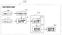
図8は、本実施の形態2に係わる路面状態推定装置20の構成を示すブロック図である。同図において、11はタイヤ内の空気圧を検出する圧力センサ、12は車輪の速度を検出する回転センサ12aの出力パルスに基づいて車速を検出する車速検出手段、13は上記圧力センサ11の出力レベルの時間軸上における変動成分を周波数解析して複数の周波数帯域における圧力変動の平均値を演算する圧力変動値演算手段、21は圧力変動値演算手段13で演算された、路面の滑り易さの影響を受けにくい帯域である300Hz〜1000Hz帯域の圧力変動平均値と、1000Hz〜5000Hz帯域の圧力変動平均値との比αを算出する圧力変動比算出手段22と、上記圧力変動比算出手段22で算出された変動比αの値から、タイヤが接地している路面状態が予め分類されたどの路面状態に相当するかを判定する路面状態判定手段23とを備えた路面状態推定手段、24は上記路面状態推定手段21で推定された路面状態から路面の滑りやすさ(危険度)を判定し、乗員に警告する路面状態警告手段である。
【0021】
図9は、上記図3で示したタイヤ内圧変動のデータから、車速がそれぞれ30km/hr、60km/hr、90km/hrである場合の、300Hz〜1000Hz帯域の圧力変動平均値と、1000Hz〜5000Hz帯域の圧力変動平均値との比αの変化を求めた図で、ウエット路でかつ高速で走行するほど、また摩耗したタイヤほど上記αの値が大きくなっており、このαを用いることにより、路面状態の危険度を更に厳密に判断することが可能となる。
このとき、路面摩擦係数μと上記αとの関係等を用いて、閾値となる基準値を設定し、路面の状態を、例えば、α<0.5なら▲1▼通常状態、0.5<α<0.8なら▲2▼要注意状態(ウエット路、雪路など)、0.8<αなら▲3▼危険状態(ハイドロプレーニング状態、圧雪路、ミラーバーンなど)の3段階に設定することにより、走行時における路面の滑り易さ=危険度を判断する。
路面状態推定手段では、路面状態判定手段23により、圧力変動比算出手段22において算出された、300Hz〜1000Hz帯域の圧力変動平均値と、1000Hz〜5000Hz帯域の圧力変動平均値との比αの値から、タイヤが接地している路面状態が予め分類された上記▲1▼〜▲3▼のどの路面状態に相当するかを判定することにより路面状態を推定し、路面状態が上記▲2▼要注意及び▲3▼危険のいずれかである場合には、上記情報を路面状態警告手段24に送り、乗員に路面の滑り易さを警報等で警告することができる。
【0022】
【実施例】
本発明の路面状態推定装置20を搭載した車両を、乾燥路と水深10mmのウエット路において、新品及び摩耗タイヤのそれぞれで、30km/hr、60km/hr、90km/hrで実際に走行してみたところ、新品のタイヤでは60km/hrで要注意の、90km/hrで危険の警報が発せられた。
一方、摩耗タイヤでは、60km/hr以上で危険の警報が発せられた。
【0023】
このように、本実施の形態2によれば、圧力センサ11で検出したタイヤ内の空気圧の変動から、路面の滑り易さの影響を受けにくい300Hz〜1000Hz帯域の圧力変動平均値と、1000Hz〜5000Hz帯域の圧力変動平均値との比αを算出算出し、上記算出された圧力変動値の比αから、タイヤが接地している路面状態を、▲1▼通常状態(α<0.5)、▲2▼要注意状態(0.5<α<0.8)、▲3▼危険状態(0.8<α)の3段階のいずれに相当するかを推定するようにしたので、走行時における路面の滑り易さ=危険度を正確に推定することができる。
なお、上記路面状態推定装置20では、路面状態警告手段24により、乗員に路面の滑り易さを警報等で警告することができるように構成したが、路面状態推定を推定してこれを車両制御へフィードバックする車両制御装置に搭載する場合には、上記路面状態警告手段24を省略することもできる。
また、上記実施の形態2の路面状態推定装置20を、上記実施の形態1のタイヤ走行状態検出装置10に組み込むことにより、タイヤの走行状態を更に精度よく検出することができる。
【0024】
【発明の効果】
以上説明したように本発明によれば、タイヤ内の空気圧の変動を検出して周波数分析し、複数の周波数帯域における上記空気圧の圧力変動値を比較して、路面状態やタイヤの異常の有無を含むタイヤの走行状態を検出するようにしたので、1個の圧力検出手段で、路面の状態やタイヤ圧、更にはタイヤの異常の有無などを精度良く検出することが可能な、シンプルな構造で、かつ、多くの機能をもった低コストのタイヤ走行状態検出装置を提供することができる。
また、本発明では、外部と遮断されているタイヤ内の空気を利用しているため、従来のようにセンサが雨に濡れたりして故障したり、周囲を走行する他の車両の影響を受けることなくタイヤの走行状態を検出することができる。
【図面の簡単な説明】
【図1】 本発明の実施の形態1に係わるタイヤ走行状態検出装置の構成を示すブロック図である。
【図2】 本実施の形態1に係わる圧力センサの設置個所を示す図である。
【図3】 タイヤ内圧変動レベルの周波数解析結果を示す図である。
【図4】 タイヤの振動レベルの周波数解析結果を示す図である。
【図5】 圧力変動から検出した固有振動数と基準空気圧との関係を示す図である。
【図6】 検出圧力の絶対値にて測定したタイヤ空気圧と基準空気圧との関係を示す図である。
【図7】 タイヤの剥離故障の検出例を示す図である。
【図8】 本実施の形態2に係わる路面状態推定装置の構成を示すブロック図である。
【図9】 タイヤ内圧変動の比であるαの変化を示す図である。
【符号の説明】
10 タイヤ走行状態検出装置、11 圧力センサ、12 車速検出手段、
12a 回転センサ,13 圧力変動値演算手段、14 タイヤ走行状態検出手段,15 走行状態検出手段、16 タイヤ圧監視手段、17 タイヤ異常検出手段、18 タイヤ走行状態警告手段、18A 走行状態警告手段、18B タイヤ圧低下警告手段、18C タイヤ異常警告手段、20 路面状態推定装置、21 路面状態推定手段、22 圧力変動比算出手段、23 路面状態判定手段、24 路面状態警告手段。[0001]
BACKGROUND OF THE INVENTION
The present invention relates to a method and an apparatus for detecting a traveling state of a tire, and a method and an apparatus for estimating a road surface state during traveling.
[0002]
[Prior art]
In order to improve the running stability of an automobile, it is required to accurately estimate a friction coefficient (road surface friction coefficient) or a road surface state between a tire and a road surface and feed it back to vehicle control. If the road surface friction coefficient and the road surface condition can be estimated in advance, for example, more advanced control of the ABS brake or the like can be performed before a risk avoidance operation such as braking / driving or steering is performed, and safety may be further increased. is expected. In addition, simply telling the driver the degree of danger of the road surface condition while driving allows the driver to perform an early deceleration operation, and can reduce the number of accidents.
Conventionally, as a method of estimating the road surface state, based on the contact sound detected by a sensor that detects a contact sound between the tire and the road surface, which is disposed in the lower part of the vehicle, for example, in the vicinity of the axle that supports the tire. Methods for estimating the road surface condition (Japanese Patent Laid-Open Nos. 8-261993 and 9-54020) have been proposed.
[0003]
[Problems to be solved by the invention]
However, the method for detecting the contact sound between the tire and the road surface from the vehicle body side as described above is often used for detection because the vehicle often travels on a wet road surface such as a rain or a puddle. Not only can the sensor get wet and break down, but it also picks up the tire contact sound of other vehicles traveling around it, so it can accurately detect the tire contact sound of the vehicle. However, it has not been put into practical use because of the problems such as difficulty in doing so.
[0004]
The present invention has been made in view of the conventional problems, and an object of the present invention is to provide a method and an apparatus for accurately detecting a running state of a tire such as a road surface state and the presence or absence of a tire abnormality.
[0005]
[Means for Solving the Problems]
The present invention utilizes the principle that tire vibration, which changes depending on the road surface condition and tire condition, is propagated to the air inside the tire and is detected as the pressure fluctuation of the air. It was made by paying attention to the fact that a plurality of physical phenomena such as the presence or absence of abnormality of the tire appear in the frequency bands with different air pressure fluctuations. That is, the present invention detects the pressure fluctuation of air sealed in pneumatic tires that are widely used at present from bicycles, two-wheeled vehicles, passenger cars to large trucks and construction vehicle tires. By analyzing the frequency of the pressure fluctuation, and detecting the change in the pressure fluctuation caused by the road surface condition and the presence or absence of abnormality of the tire appearing in the different frequency bands described above, the tire running state is detected. Since the air in the tire that is blocked from the outside is used, the running state of the tire can be accurately detected without being affected by water or other vehicles traveling around like the conventional example above. Is possible.
[0006]
[Means for Solving the Problems]
According to a first aspect of the present invention, there is provided a method for detecting a tire traveling state, detecting a variation in air pressure in a tire of a vehicle, performing frequency analysis, comparing pressure variation values of the air pressure in a plurality of frequency bands, and road surfaces. The present invention is characterized in that the running state of the tire including the state and the presence or absence of abnormality of the tire is detected.
Further, the tire running state detection device according to
The tire running state detection device according to
The tire running state detection device according to claim 4 frequency-analyzes the time fluctuation of the air pressure detected by the pressure detecting means, calculates an average value of the pressure fluctuation value of the air pressure in a frequency band of 100 Hz or less, When the average value of the calculated pressure fluctuation values exceeds a preset reference value, there is provided tire abnormality detection means for determining that the running tire has an abnormality due to tread peeling. When peeling occurs in a part of the tread portion, vibration is generated every time the portion comes into contact with the road surface, and air on the tire inner surface is excited. Therefore, it is possible to detect a failure of the tire by detecting the vibration as a pressure fluctuation of the tire air pressure.
Claim5In the tire running state detecting device described in 1), the pressure detecting means is constituted by a semiconductor or piezoelectric pressure sensor, or a semiconductor or piezoelectric microphone.
Claim6In order to detect the tire running state with higher accuracy, the tire running state detection device described in 1) compares the pressure fluctuation values in the calculated frequency bands according to the vehicle speed detected by the vehicle speed detecting means. It is a thing.
[0009]
By the way, the rolling tire always vibrates, but the restraint state of the tread portion in contact with the road surface changes depending on the slipperiness of the road surface, and this becomes a difference in vibration in a high frequency band of 800 Hz to 5000 Hz. appear. By comparing the magnitude of this vibration with vibration in a frequency band that is less affected by the slipperiness of the road surface, the road surface state can be estimated more accurately.
[0010]
Claims of the invention7The road surface state estimation method described in 1) detects fluctuations in the air pressure in the tire, calculates pressure fluctuation values in at least two frequency bands of the air pressure, and determines that the tire is grounded from the ratio of the calculated pressure fluctuation values. The road surface condition is estimated.
Claim8The road surface state estimating device described in 1) is a pressure detection unit that is attached to a tire or a wheel and detects the air pressure in the tire, and frequency analyzes the time variation of the detected air pressure, and at least in two frequency bands. Means for calculating an average value of pressure fluctuations of the pressure, and pressure fluctuations in the calculated frequency bandsofRoad surface state estimating means for estimating the road surface state is provided from the ratio of the average values, and the road surface state where the tire is in contact with the ground is estimated.
Claim9In the road surface state estimating device described in 1), the pressure detecting means is constituted by a semiconductor or piezoelectric pressure sensor, or a semiconductor or piezoelectric microphone.
Claim10The road surface state estimating device according to
[0011]
Claims11The road surface state estimating device described in 1 sets one frequency band of the above frequency bands to 300 Hz to 1200 Hz, which is a band that characterizes the input from the road surface to the tire, and sets the other frequency band to the slip of the road surface. The pressure fluctuation on the low frequency side is set at 800 Hz to 5000 Hz which is a band characterizing ease.ofPressure fluctuation on the high frequency side with respect to the average valueofThe ratio of the average value is the preset reference valueSuperIn this case, road surface state estimating means for estimating that the road surface is in a slippery state is provided. Since the vibration in the 300 Hz to 1200 Hz band is not easily affected by the slipperiness of the road surface, as a means for separating disturbance factors other than the slipperiness of the road surface from the 800 Hz to 5000 Hz band value, the ratio with the 300 Hz to 1200 Hz band value It is possible to accurately estimate the slipperiness of the road surface.
Claim12The road surface state estimation device according to the above is configured such that the vehicle travels in advance at various road surface states and speeds, and the braking distance of the vehicle and the pressure fluctuation at that timeofAverage value ratioWhenThe road surface friction coefficient obtained from the braking distance and the measured pressure fluctuationofThe reference value is calculated from the ratio of average values..
[0012]
DETAILED DESCRIPTION OF THE INVENTION
Hereinafter, embodiments of the present invention will be described with reference to the drawings.
FIG. 1 is a block diagram showing a configuration of a tire running
[0013]
In the first embodiment, the pressure sensor 11 for detecting the air pressure in the tire is attached to the tire side (not shown) of the
The pressure sensor 11 can use various types such as a piezoelectric type and a semiconductor type as long as it has an accuracy capable of detecting a high-frequency pressure fluctuation. Moreover, what is generally called a microphone is also a sensor that detects pressure vibration of air, and can be used as a pressure sensor.
[0014]
FIG. 3 is a diagram showing an example of in-tire pressure fluctuation data obtained by detecting the pressure fluctuation in the running tire by the pressure sensor 11. This tire pressure fluctuation data is obtained by running two types of vehicles with new and worn tires on the vehicle at a traveling speed of 90 km / hr on two types of road surfaces, a dry road and a wet road with a water depth of 10 mm. , Δt = 160 ms sampling time, measured for 3 seconds and averaged on the frequency axis. Further, FIG. 4 shows tread vibration data during traveling measured with a vibration sensor attached to the inner surface of the tire tread for the purpose of verification and simultaneously with the above-described pressure fluctuation in the tire.
As is well known, hydroplaning occurs when driving on a wet road at a high speed at a high speed, and the vehicle falls into a very dangerous state where it cannot be controlled. In particular, a worn tire is prone to hydroplaning and is dangerous.
From the measurement results shown in FIG. 4, in the state where hydroplaning occurs and the tire is slippery, tread vibration in a high frequency region of 800 Hz or higher is greatly increased, and particularly in a worn tire where hydroplaning is likely to occur, the vibration described above. It can be seen that is large.
On the other hand, since the fluctuation value of the pressure in the tire shown in FIG. 3 also shows the same result as in FIG. 4, the tread vibration propagates to the air in the tire and can be regarded as a pressure fluctuation in the same frequency band. It can be seen that it is. As a result, it was confirmed that the tire vibration that changes depending on the road surface condition and the tire condition can be detected as the pressure fluctuation of the air inside the tire.
Therefore, the running state detecting means 15 compares the pressure fluctuation average value in the frequency band of 800 Hz or more of the air pressure in the tire detected by the pressure sensor 11 calculated by the pressure fluctuation value calculating means 13. It becomes possible to detect whether the state is a state where hydroplaning occurs and the tire is slippery. That is, the map storage means 15M stores in advance the relationship between the tire pressure fluctuation level and the frequency obtained from the above experimental results as a map, and the pressure fluctuation average value in the frequency band of 800 Hz or higher using the map. Is compared with the data on the dry road or wet road of the map to detect whether or not the tire is slippery.
[0015]
When the running state is a state in which hydroplaning is likely to occur, the running
From the above experimental results, the tire pressure obtained from the pressure sensor 11 is set by setting a threshold value of the pressure fluctuation average value in a high frequency region of 800 Hz or higher where hydroplaning is likely to occur.PressureYou may make it detect whether a tire is a slippery state by comparing a fluctuation average value with the said threshold value.
In addition, if the above running experiment is performed at various vehicle speeds and it is detected whether the tire is slippery or not by using a map or threshold value for each vehicle speed, the state in which hydroplaning is likely to occur is more accurately determined. can do.
[0016]
Further, in this example, the tire pressure monitoring means 16 detects the tire air pressure from the peak frequency of the pressure fluctuation within the frequency band of 100 Hz or less calculated by the pressure fluctuation value calculating means 13, and determines the tire pressure during traveling. I always try to monitor it. Specifically, the tire pressure monitoring means 16 detects the natural frequency of the tire in the vicinity of 40 Hz from the peak frequency of the fluctuation value of the in-tire pressure shown in FIG. The pressure in the tire is detected using a graph showing the relationship between the reference air pressure measured using a calibrated air pressure gauge and the natural frequency.
When the detected tire pressure falls below a predetermined pressure value, the information is sent to the tire pressure drop warning means 18B of the tire running state warning means 18 to warn the occupant that the tire pressure has dropped. To do.
In the case where the absolute value of the output of the pressure sensor 11 is a sensor that has been confirmed to correspond to a reference air pressure measured beforehand using an air pressure gauge, as shown in FIG. What is necessary is just to comprise so that the output of the said pressure sensor 11 may be sent to the tire pressure monitoring means 16 directly as shown with a broken line.
[0017]
In this example, the tire abnormality detecting means 17 further detects an average value of periodic pressure fluctuations that change according to the tire rotation speed within a frequency band of 100 Hz or less, and the average value is a predetermined reference value. If it exceeds, it is determined that there is an abnormality in the tire, and the information is sent to the tire abnormality warning means 18C of the tire running state warning means 18 to warn the occupant that a tire abnormality has occurred.
For example, when peeling occurs in a part of the tread portion, vibration is generated every time the portion comes into contact with the road surface, and the air on the tire inner surface is vibrated. Normally, an initial peeling failure occurs at one location on the tire circumference, and the vibration generated thereby becomes periodic according to the tire rotation speed. For example, in the case of a general passenger car tire, the cycle is about 14 Hz (primary), 28 Hz (secondary), 4 at a speed of 100 km / hr.2Hz (tertiary), .... Even during normal driving, the above-mentioned peak occurs when the tire is in contact with the ground. However, as described above, when a failure such as peeling occurs at one place on the circumference, the peak level becomes extremely large. It is presumed that some abnormality has occurred.
FIG. 7 shows a result of producing a faulty tire intentionally cut at one place on the circumference between the tire tread and the steel belt, measuring the fluctuation of the tire pressure of the faulty tire, and comparing it with a normal tire. FIG. Specifically, the failed tire and the normal tire were run on an indoor drum at a constant speed of 100 km / hr, pressure fluctuations in the tire were measured, and frequency analysis was performed.
As described above, even a normal tire is about 14 Hz (primary), 28 Hz (secondary), 42HA peak occurs at the frequency of z (third order),..., but in the case of a faulty tire, as shown by the broken line in FIG. This is significantly higher than twice the normal state peak at the above frequency (6 dB), which is set as a reference for detecting a tire failure. By detecting the pressure fluctuation of the tire pressure in this way, It can be seen that a failure can be detected.
Here, the above reference value is applied to the vehicle and the tire.AbnormalThe reference determination frequency F when the vehicle is driven at a predetermined vehicle speed V in a state where no occurrence occurs.nBy setting the pressure fluctuation level at 2 × n × V / (2πr) to a value that is doubled, the abnormality can be detected with high accuracy. In the above formula, r is a tire rolling radius and n is a natural number.
The reference value can be changed according to changes over time such as temperature, tire tread wear or rubber hardness deterioration.
[0018]
As described above, the tire running
In addition, since this device uses the air in the tire that is blocked from the outside, the sensor is damaged by rain or is affected by other vehicles traveling around as in the past. The running state of the tire can be detected without any trouble.
Furthermore, the single pressure sensor 11 can detect the road surface condition, tire pressure, and the presence / absence of an abnormality in the tire, so that it has a simple structure and a low cost with many functions. A tire running state detection device can be provided.
[0019]
In the first embodiment, the device for simultaneously detecting the road surface condition, the tire pressure, the presence / absence of tire abnormality, and the like has been described. However, each function is configured separately, and the running state of the vehicle causes hydroplaning. It is also possible to produce warning devices such as a driving state warning device that warns of a dangerous state, a tire pressure reduction warning device that warns of a decrease in tire pressure, and a tire abnormality warning device that warns of tire abnormality. .
[0020]
FIG. 8 is a block diagram showing a configuration of the road surface
[0021]
FIG. 9 shows the pressure fluctuation average values in the 300 Hz to 1000 Hz band and 1000 Hz to 5000 Hz when the vehicle speed is 30 km / hr, 60 km / hr, and 90 km / hr, respectively, based on the tire internal pressure fluctuation data shown in FIG. In the figure which calculated | required the change of ratio (alpha) with the pressure fluctuation average value of a zone | band, the value of said (alpha) is so large that it drive | runs on a wet road and high speed, and the tire which was worn out, By using this (alpha), It becomes possible to judge the risk of the road surface condition more strictly.
At this time, a reference value serving as a threshold value is set using the relationship between the road surface friction coefficient μ and the above α, and the road surface state is set to, for example, α <0.5, (1) normal state, 0.5 < If α <0.8, set to 3 levels: ▲ 2 cautionary state (wet road, snowy road, etc.), and 0.8 <α, ▲ 3 ▼ dangerous state (hydroplaning, snowy road, mirror burn, etc.). Thus, it is determined whether the slipperiness of the road surface during traveling is equal to the danger level.
In the road surface state estimating means, the value α of the ratio α between the pressure fluctuation average value in the 300 Hz to 1000 Hz band and the pressure fluctuation average value in the 1000 Hz to 5000 Hz band calculated by the pressure fluctuation ratio calculating means 22 by the road surface state determining means 23. From the above, the road surface state where the tire is in contact with the ground is estimated by determining which road surface state of the above-mentioned (1) to (3) corresponds to the road surface state. In the case of any one of caution and (3) danger, the above information can be sent to the road surface warning means 24 to warn the occupant of the slipperiness of the road surface with an alarm or the like.
[0022]
【Example】
A vehicle equipped with the road surface
On the other hand, a danger warning was issued at 60 km / hr or more for worn tires.
[0023]
As described above, according to the second embodiment, the pressure fluctuation average value in the 300 Hz to 1000 Hz band that is not easily affected by the slipperiness of the road surface from the fluctuation of the air pressure in the tire detected by the pressure sensor 11, and 1000 Hz to Calculate and calculate the ratio α to the pressure fluctuation average value in the 5000 Hz band, and from the calculated pressure fluctuation value ratio α, the road surface condition where the tire is in contact is determined as follows: (1) Normal state (α <0.5) , (2) Since it is estimated that it corresponds to three stages of caution state (0.5 <α <0.8) and (3) dangerous state (0.8 <α), It is possible to accurately estimate the slipperiness of the road surface = the risk level.
The road surface
Further, by incorporating the road surface
[0024]
【The invention's effect】
As described above, according to the present invention, the fluctuation of the air pressure in the tire is detected and subjected to frequency analysis, and the pressure fluctuation values of the air pressure in a plurality of frequency bands are compared to determine whether there is a road surface condition or tire abnormality. Since it is designed to detect the running state of tires, it has a simple structure that can accurately detect road surface conditions, tire pressure, and whether there are tire abnormalities, etc. with a single pressure detection means. In addition, it is possible to provide a low-cost tire running state detection device having many functions.
Further, in the present invention, since the air in the tire that is blocked from the outside is used, the sensor is damaged by rain or is affected by other vehicles traveling around as in the past. The running state of the tire can be detected without any trouble.
[Brief description of the drawings]
FIG. 1 is a block diagram illustrating a configuration of a tire running state detection device according to a first embodiment of the present invention.
FIG. 2 is a diagram showing an installation location of a pressure sensor according to the first embodiment.
FIG. 3 is a diagram showing a frequency analysis result of a tire internal pressure fluctuation level.
FIG. 4 is a diagram illustrating a frequency analysis result of a tire vibration level.
FIG. 5 is a diagram showing a relationship between a natural frequency detected from pressure fluctuation and a reference air pressure.
FIG. 6 is a diagram showing a relationship between tire air pressure measured with an absolute value of detected pressure and a reference air pressure.
FIG. 7 is a view showing a detection example of a tire peeling failure.
FIG. 8 is a block diagram showing a configuration of a road surface state estimation apparatus according to the second embodiment.
FIG. 9 is a diagram showing a change in α, which is a ratio of tire internal pressure fluctuations.
[Explanation of symbols]
10 tire running state detecting device, 11 pressure sensor, 12 vehicle speed detecting means,
12a Rotation sensor, 13 Pressure fluctuation value calculating means, 14 Tire running condition detecting means, 15 Running condition detecting means, 16 Tire pressure monitoring means, 17 Tire abnormality detecting means, 18 Tire running condition warning means, 18A Running condition warning means, 18B Tire pressure drop warning means, 18C tire abnormality warning means, 20 road surface state estimation device, 21 road surface state estimation means, 22 pressure fluctuation ratio calculation means, 23 road surface state determination means, 24 road surface warning means.
Claims (12)
上記検出された空気圧の時間変動を周波数分析して、800Hz以上の周波数帯域における上記空気圧の圧力変動値の平均値を算出する手段と、
上記算出された圧力変動値の平均値から、走行中のタイヤが滑り易い状態にあるか否かを検出する走行状態検出手段とを備えたことを特徴とするタイヤ走行状態検出装置。Pressure detecting means attached to the tire or wheel for detecting the air pressure in the tire;
Means for frequency-analyzing the detected time variation of the air pressure and calculating an average value of the pressure variation value of the air pressure in a frequency band of 800 Hz or higher ;
A tire running state detecting device comprising: a running state detecting means for detecting whether or not a running tire is in a slippery state from the calculated average value of pressure fluctuation values.
Priority Applications (1)
| Application Number | Priority Date | Filing Date | Title |
|---|---|---|---|
| JP2001036048A JP4629246B2 (en) | 2001-02-13 | 2001-02-13 | Tire running state detection method, tire running state detection device, road surface state estimation method, and road surface state estimation device |
Applications Claiming Priority (1)
| Application Number | Priority Date | Filing Date | Title |
|---|---|---|---|
| JP2001036048A JP4629246B2 (en) | 2001-02-13 | 2001-02-13 | Tire running state detection method, tire running state detection device, road surface state estimation method, and road surface state estimation device |
Publications (2)
| Publication Number | Publication Date |
|---|---|
| JP2002240520A JP2002240520A (en) | 2002-08-28 |
| JP4629246B2 true JP4629246B2 (en) | 2011-02-09 |
Family
ID=18899387
Family Applications (1)
| Application Number | Title | Priority Date | Filing Date |
|---|---|---|---|
| JP2001036048A Expired - Fee Related JP4629246B2 (en) | 2001-02-13 | 2001-02-13 | Tire running state detection method, tire running state detection device, road surface state estimation method, and road surface state estimation device |
Country Status (1)
| Country | Link |
|---|---|
| JP (1) | JP4629246B2 (en) |
Families Citing this family (18)
| Publication number | Priority date | Publication date | Assignee | Title |
|---|---|---|---|---|
| ES2534480T3 (en) * | 2001-12-21 | 2015-04-23 | Kabushiki Kaisha Bridgestone | Method and apparatus for estimating the state of the surface of a road and the running state of a tire |
| FR2856145B1 (en) * | 2003-06-16 | 2005-09-02 | Michelin Soc Tech | DETECTION OF THE REVOLUTIONS OF A PNEUMATIC ASSEMBLY AND WHEEL, USING THE TERRESTRIAL MAGNETIC FIELD. |
| EP1693231B1 (en) * | 2003-12-12 | 2011-07-27 | Bridgestone Corporation | Device and method for detecting abnormality of rotating body |
| JP4732848B2 (en) * | 2004-11-02 | 2011-07-27 | 株式会社ブリヂストン | Abnormality determination apparatus and abnormality determination method |
| EP1826028A4 (en) * | 2004-11-02 | 2010-07-28 | Bridgestone Corp | Abnormality judging device |
| US8051705B2 (en) | 2006-11-14 | 2011-11-08 | Kabushiki Kaisha Bridgestone | Tire equipped with a sensor and a method of measuring strain amount of the tire |
| JP4629756B2 (en) * | 2008-07-14 | 2011-02-09 | 株式会社ブリヂストン | Road surface state estimation method and road surface state estimation device |
| JP5272559B2 (en) * | 2008-07-25 | 2013-08-28 | トヨタ自動車株式会社 | Hydroplaning generation speed estimation device |
| JP2014193667A (en) * | 2013-03-28 | 2014-10-09 | Jtekt Corp | Vehicle steering device |
| FR3015036B1 (en) * | 2013-12-18 | 2016-01-22 | Michelin & Cie | METHOD OF ACOUSTICALLY DETECTING THE CONDITION OF ROAD AND TIRE |
| KR101544886B1 (en) * | 2014-07-07 | 2015-08-17 | 현대오트론 주식회사 | Method and System for Monitoring Pressure of Tire |
| TWI604971B (en) * | 2016-01-08 | 2017-11-11 | Dynamic air pressure sensing system for bicycles | |
| KR20180081280A (en) * | 2017-01-06 | 2018-07-16 | 우 치엔-첸 | A dynamic tire pressure sensor system for a bike |
| US10569785B2 (en) * | 2017-04-27 | 2020-02-25 | Ford Global Technologies, Llc | Road water detection |
| DE102018211211A1 (en) * | 2018-07-06 | 2020-01-09 | Continental Automotive Gmbh | Method for detecting an incorrect arrangement of a sensor module in a sensor module holder in a tire monitoring system of a vehicle |
| DE102019101704A1 (en) * | 2019-01-24 | 2020-07-30 | Man Truck & Bus Se | Method and device for controlling a vehicle starting aid |
| US20220348045A1 (en) * | 2019-11-15 | 2022-11-03 | Pirelli Tyre S.P.A. | Method and system for estimating a vehicle body motion during the running of a vehicle along a road segment |
| CN114750543A (en) * | 2022-04-18 | 2022-07-15 | 东风柳州汽车有限公司 | Tire replacement reminding method, device, equipment and storage medium |
Citations (7)
| Publication number | Priority date | Publication date | Assignee | Title |
|---|---|---|---|---|
| JPH06258196A (en) * | 1993-03-04 | 1994-09-16 | Toyota Motor Corp | Detector of road face friction coefficient |
| JPH09188238A (en) * | 1995-11-24 | 1997-07-22 | Daimler Benz Ag | Early detection method of vehicle tire flotation on wet road |
| WO1999028172A1 (en) * | 1997-11-28 | 1999-06-10 | Denso Corporation | Vehicle controller |
| JP2001215175A (en) * | 1999-12-03 | 2001-08-10 | Trw Inc | System and method for monitoring vehicle state exerting effect on tire |
| WO2001087647A1 (en) * | 2000-04-12 | 2001-11-22 | Nira Dynamics Ab | Tire pressure estimation |
| WO2001098123A1 (en) * | 2000-06-23 | 2001-12-27 | Kabushiki Kaisha Bridgestone | Method for estimating vehicular running state, vehicular running state estimating device, vehicle control device, and tire wheel |
| JP2003526560A (en) * | 2000-03-16 | 2003-09-09 | ピレリ・プネウマティチ・ソチエタ・ペル・アツィオーニ | System, tire and method for determining tire behavior during operation |
-
2001
- 2001-02-13 JP JP2001036048A patent/JP4629246B2/en not_active Expired - Fee Related
Patent Citations (7)
| Publication number | Priority date | Publication date | Assignee | Title |
|---|---|---|---|---|
| JPH06258196A (en) * | 1993-03-04 | 1994-09-16 | Toyota Motor Corp | Detector of road face friction coefficient |
| JPH09188238A (en) * | 1995-11-24 | 1997-07-22 | Daimler Benz Ag | Early detection method of vehicle tire flotation on wet road |
| WO1999028172A1 (en) * | 1997-11-28 | 1999-06-10 | Denso Corporation | Vehicle controller |
| JP2001215175A (en) * | 1999-12-03 | 2001-08-10 | Trw Inc | System and method for monitoring vehicle state exerting effect on tire |
| JP2003526560A (en) * | 2000-03-16 | 2003-09-09 | ピレリ・プネウマティチ・ソチエタ・ペル・アツィオーニ | System, tire and method for determining tire behavior during operation |
| WO2001087647A1 (en) * | 2000-04-12 | 2001-11-22 | Nira Dynamics Ab | Tire pressure estimation |
| WO2001098123A1 (en) * | 2000-06-23 | 2001-12-27 | Kabushiki Kaisha Bridgestone | Method for estimating vehicular running state, vehicular running state estimating device, vehicle control device, and tire wheel |
Also Published As
| Publication number | Publication date |
|---|---|
| JP2002240520A (en) | 2002-08-28 |
Similar Documents
| Publication | Publication Date | Title |
|---|---|---|
| JP4629246B2 (en) | Tire running state detection method, tire running state detection device, road surface state estimation method, and road surface state estimation device | |
| JP4868689B2 (en) | Road surface state estimation method and road surface state estimation device | |
| US8904869B2 (en) | Alarm method for indicating the wear of a tyre with a groove | |
| JP3856389B2 (en) | Tire pressure monitoring device | |
| JP4263400B2 (en) | Road friction coefficient estimation method and road friction coefficient estimation device | |
| JP4596782B2 (en) | Method and system for monitoring tires during vehicle travel | |
| US6002327A (en) | Low tire warning system with axle torque signal | |
| JP4549975B2 (en) | Tire condition estimation method | |
| EP1263616B1 (en) | System, tyre and method for determining the behaviour of a tyre in motion | |
| JP2917135B2 (en) | Method and apparatus for monitoring tires in vehicles | |
| US7340369B2 (en) | Detection device for decreased tire pressures and method thereof | |
| JPH10193931A (en) | Tire air pressure drop alarm device | |
| JP4629756B2 (en) | Road surface state estimation method and road surface state estimation device | |
| US7512473B2 (en) | Method for judging road surface condition and device thereof, and program for judging road surface condition | |
| JP4964328B2 (en) | Tire pressure drop detection device, method and program | |
| JP3993899B2 (en) | Safety insert that generates a transverse vibration signal and device for detecting tire support on the safety insert | |
| JPH10100621A (en) | Tire pneumatic pressure lowering detecting method and device thereof | |
| JP2002087032A (en) | Hydroplaning detecting method, hydroplaning detecting device and vehicle control system | |
| JP4509324B2 (en) | Estimation method of road friction coefficient | |
| JP5097901B2 (en) | Method for determining the load state of a vehicle | |
| JP3961305B2 (en) | Tire pressure alarm device | |
| JP3802812B2 (en) | Detection method for differential limiting device, tire pressure drop detection method using the detection method, device, and tire decompression determination program | |
| JP3146733B2 (en) | Tire pressure detector | |
| JP2003252191A (en) | Method and device for estimating road surface condition | |
| CN113165457B (en) | Method for detecting the risk of blowout of a tyre |
Legal Events
| Date | Code | Title | Description |
|---|---|---|---|
| A621 | Written request for application examination |
Free format text: JAPANESE INTERMEDIATE CODE: A621 Effective date: 20080131 |
|
| A977 | Report on retrieval |
Free format text: JAPANESE INTERMEDIATE CODE: A971007 Effective date: 20100318 |
|
| A131 | Notification of reasons for refusal |
Free format text: JAPANESE INTERMEDIATE CODE: A131 Effective date: 20100511 |
|
| A521 | Written amendment |
Free format text: JAPANESE INTERMEDIATE CODE: A523 Effective date: 20100709 |
|
| TRDD | Decision of grant or rejection written | ||
| A01 | Written decision to grant a patent or to grant a registration (utility model) |
Free format text: JAPANESE INTERMEDIATE CODE: A01 Effective date: 20101109 |
|
| A01 | Written decision to grant a patent or to grant a registration (utility model) |
Free format text: JAPANESE INTERMEDIATE CODE: A01 |
|
| A61 | First payment of annual fees (during grant procedure) |
Free format text: JAPANESE INTERMEDIATE CODE: A61 Effective date: 20101111 |
|
| FPAY | Renewal fee payment (event date is renewal date of database) |
Free format text: PAYMENT UNTIL: 20131119 Year of fee payment: 3 |
|
| R150 | Certificate of patent or registration of utility model |
Free format text: JAPANESE INTERMEDIATE CODE: R150 |
|
| LAPS | Cancellation because of no payment of annual fees |