JP4623973B2 - Torque converter - Google Patents
Torque converter Download PDFInfo
- Publication number
- JP4623973B2 JP4623973B2 JP2004010259A JP2004010259A JP4623973B2 JP 4623973 B2 JP4623973 B2 JP 4623973B2 JP 2004010259 A JP2004010259 A JP 2004010259A JP 2004010259 A JP2004010259 A JP 2004010259A JP 4623973 B2 JP4623973 B2 JP 4623973B2
- Authority
- JP
- Japan
- Prior art keywords
- clutch
- chamber
- pressure
- converter
- lock
- Prior art date
- Legal status (The legal status is an assumption and is not a legal conclusion. Google has not performed a legal analysis and makes no representation as to the accuracy of the status listed.)
- Expired - Fee Related
Links
Images


Classifications
-
- F—MECHANICAL ENGINEERING; LIGHTING; HEATING; WEAPONS; BLASTING
- F16—ENGINEERING ELEMENTS AND UNITS; GENERAL MEASURES FOR PRODUCING AND MAINTAINING EFFECTIVE FUNCTIONING OF MACHINES OR INSTALLATIONS; THERMAL INSULATION IN GENERAL
- F16H—GEARING
- F16H45/00—Combinations of fluid gearings for conveying rotary motion with couplings or clutches
- F16H45/02—Combinations of fluid gearings for conveying rotary motion with couplings or clutches with mechanical clutches for bridging a fluid gearing of the hydrokinetic type
- F16H2045/021—Combinations of fluid gearings for conveying rotary motion with couplings or clutches with mechanical clutches for bridging a fluid gearing of the hydrokinetic type three chamber system, i.e. comprising a separated, closed chamber specially adapted for actuating a lock-up clutch
-
- F—MECHANICAL ENGINEERING; LIGHTING; HEATING; WEAPONS; BLASTING
- F16—ENGINEERING ELEMENTS AND UNITS; GENERAL MEASURES FOR PRODUCING AND MAINTAINING EFFECTIVE FUNCTIONING OF MACHINES OR INSTALLATIONS; THERMAL INSULATION IN GENERAL
- F16H—GEARING
- F16H45/00—Combinations of fluid gearings for conveying rotary motion with couplings or clutches
- F16H45/02—Combinations of fluid gearings for conveying rotary motion with couplings or clutches with mechanical clutches for bridging a fluid gearing of the hydrokinetic type
- F16H2045/0221—Combinations of fluid gearings for conveying rotary motion with couplings or clutches with mechanical clutches for bridging a fluid gearing of the hydrokinetic type with damping means
- F16H2045/0226—Combinations of fluid gearings for conveying rotary motion with couplings or clutches with mechanical clutches for bridging a fluid gearing of the hydrokinetic type with damping means comprising two or more vibration dampers
- F16H2045/0231—Combinations of fluid gearings for conveying rotary motion with couplings or clutches with mechanical clutches for bridging a fluid gearing of the hydrokinetic type with damping means comprising two or more vibration dampers arranged in series
-
- F—MECHANICAL ENGINEERING; LIGHTING; HEATING; WEAPONS; BLASTING
- F16—ENGINEERING ELEMENTS AND UNITS; GENERAL MEASURES FOR PRODUCING AND MAINTAINING EFFECTIVE FUNCTIONING OF MACHINES OR INSTALLATIONS; THERMAL INSULATION IN GENERAL
- F16H—GEARING
- F16H45/00—Combinations of fluid gearings for conveying rotary motion with couplings or clutches
- F16H45/02—Combinations of fluid gearings for conveying rotary motion with couplings or clutches with mechanical clutches for bridging a fluid gearing of the hydrokinetic type
- F16H2045/0221—Combinations of fluid gearings for conveying rotary motion with couplings or clutches with mechanical clutches for bridging a fluid gearing of the hydrokinetic type with damping means
- F16H2045/0247—Combinations of fluid gearings for conveying rotary motion with couplings or clutches with mechanical clutches for bridging a fluid gearing of the hydrokinetic type with damping means having a turbine with hydrodynamic damping means
-
- F—MECHANICAL ENGINEERING; LIGHTING; HEATING; WEAPONS; BLASTING
- F16—ENGINEERING ELEMENTS AND UNITS; GENERAL MEASURES FOR PRODUCING AND MAINTAINING EFFECTIVE FUNCTIONING OF MACHINES OR INSTALLATIONS; THERMAL INSULATION IN GENERAL
- F16H—GEARING
- F16H45/00—Combinations of fluid gearings for conveying rotary motion with couplings or clutches
- F16H45/02—Combinations of fluid gearings for conveying rotary motion with couplings or clutches with mechanical clutches for bridging a fluid gearing of the hydrokinetic type
- F16H2045/0273—Combinations of fluid gearings for conveying rotary motion with couplings or clutches with mechanical clutches for bridging a fluid gearing of the hydrokinetic type characterised by the type of the friction surface of the lock-up clutch
- F16H2045/0284—Multiple disk type lock-up clutch
-
- F—MECHANICAL ENGINEERING; LIGHTING; HEATING; WEAPONS; BLASTING
- F16—ENGINEERING ELEMENTS AND UNITS; GENERAL MEASURES FOR PRODUCING AND MAINTAINING EFFECTIVE FUNCTIONING OF MACHINES OR INSTALLATIONS; THERMAL INSULATION IN GENERAL
- F16H—GEARING
- F16H61/00—Control functions within control units of change-speed- or reversing-gearings for conveying rotary motion ; Control of exclusively fluid gearing, friction gearing, gearings with endless flexible members or other particular types of gearing
- F16H61/14—Control of torque converter lock-up clutches
Landscapes
- Engineering & Computer Science (AREA)
- General Engineering & Computer Science (AREA)
- Mechanical Engineering (AREA)
- Control Of Fluid Gearings (AREA)
Description
本発明は、ロックアップクラッチが装着されるトルクコンバータに関する。 The present invention relates to a torque converter to which a lockup clutch is attached.
トルクコンバータは、エンジン出力軸に連結されたフロントカバーつまりトルコンカバーに取り付けられるとともにポンプインペラが設けられたインペラシェルと、ポンプインペラに対向してメインシャフトに連結されるタービンランナとを有し、トルクコンバータの出力軸であるメインシャフトにエンジン出力を増幅して伝達する動力伝達装置である。このトルクコンバータは、動力伝達媒体である作動油を利用してエンジン出力を伝達するものであるため、流体の滑りによる動力伝達ロスを避けられない。そこで、ポンプインペラとタービンランナとの回転数差が小さい領域では、ロックアップクラッチを作動させることによって、エンジン出力をメインシャフトに直接伝達するようにしている。 The torque converter has an impeller shell attached to a front cover, that is, a torque converter cover connected to an engine output shaft and provided with a pump impeller, and a turbine runner connected to a main shaft so as to face the pump impeller, and torque A power transmission device that amplifies and transmits engine output to a main shaft that is an output shaft of a converter. Since this torque converter transmits the engine output using hydraulic oil that is a power transmission medium, power transmission loss due to fluid slip is inevitable. Therefore, in a region where the rotational speed difference between the pump impeller and the turbine runner is small, the engine output is directly transmitted to the main shaft by operating the lockup clutch.
一般的なロックアップクラッチは、メインシャフトに連結されるクラッチプレートを備え、クラッチプレートをフロントカバーに係合させることによってエンジン出力をメインシャフトに直接伝達するようにしている。このクラッチプレートの作動は、クラッチプレートとタービンランナとの間に形成されるコンバータ室に供給される作動油と、クラッチプレートとフロントカバーとの間に形成されるクラッチ室に供給される作動油との差圧により制御される。つまり、クラッチプレートとフロントカバーとの係合を解いてロックアップクラッチを開放するには、クラッチ室にコンバータ室の圧力よりも高圧の作動油を解除油圧として供給するようにしている。クラッチ室にコンバータ室の油圧よりも高圧の解除油圧を供給すると、フロントカバーに圧着していたクラッチプレートが離れ、クラッチ室内の作動油はコンバータ室へと流れ込む。コンバータ室には作動油が常時供給されているから、クラッチ室への作動油の供給を停止すれば、コンバータ室の油圧によってクラッチプレートはフロントカバーに係合する。 A general lockup clutch includes a clutch plate coupled to a main shaft, and an engine output is directly transmitted to the main shaft by engaging the clutch plate with a front cover. The operation of the clutch plate includes hydraulic oil supplied to the converter chamber formed between the clutch plate and the turbine runner, and hydraulic oil supplied to the clutch chamber formed between the clutch plate and the front cover. It is controlled by the differential pressure. That is, in order to release the lockup clutch by releasing the engagement between the clutch plate and the front cover, hydraulic oil having a pressure higher than the pressure in the converter chamber is supplied to the clutch chamber as the release hydraulic pressure. When release hydraulic pressure higher than the hydraulic pressure in the converter chamber is supplied to the clutch chamber, the clutch plate that has been pressure-bonded to the front cover is released, and the hydraulic oil in the clutch chamber flows into the converter chamber. Since hydraulic oil is constantly supplied to the converter chamber, if the supply of hydraulic oil to the clutch chamber is stopped, the clutch plate is engaged with the front cover by the hydraulic pressure of the converter chamber.
このようなロックアップクラッチには、フロントカバーに設けられたクラッチドラムとメインシャフトに連結されたクラッチハブとの間に複数枚のクラッチプレートを配置するようにした多板クラッチを用いるものがある(例えば、特許文献1および2参照)。特許文献1および特許文献2に開示されるロックアップクラッチは、多板クラッチを係合させてエンジン出力をメインシャフトに直結させる締結状態と、係合を開放する開放状態とに切り換えるためのピストンを有しており、ピストンとフロントカバーとの間に締結用の油圧室が形成されている。このように多板クラッチを用いると、クラッチプレートの外径を小さくすることができ、ロックアップクラッチのコンパクト化を図りやすく、その空スペースにハイブリッドシステムを構成する発電モータを設置することができる。
しかしながら、ピストンとフロントカバーとの間に締結用の油圧室を形成すると、ピストンにはコンバータ室の油圧がクラッチ開放方向に加わっているので、クラッチの締結時にはコンバータ室の油圧により加わる開放方向に抗してピストンを駆動させるために、コンバータ室よりも高圧の作動油を締結用の油圧室に供給する必要がある。このようにクラッチ締結用の油圧をコンバータ室に供給される油圧よりも高圧にしなければならないので、オイルポンプの負担を増加させることになり伝達効率の向上を図るうえでは好ましくなく、エンジンの燃費を低減させることができない。また、ロックアップクラッチの小型化のためロックアップピストンを小径にすると、受圧面積を縮小するので、締結用の油圧をより高圧にしなければならなくなり、受圧面積を確保するために、多板クラッチをメインシャフトから比較的外方に配置するとともにロックアップピストンの径を大きくすると、その分だけロックアップクラッチが大型化することになる。 However, if a fastening hydraulic chamber is formed between the piston and the front cover, the piston chamber is pressurized with the hydraulic pressure in the converter chamber in the clutch opening direction. In order to drive the piston, it is necessary to supply hydraulic oil having a pressure higher than that of the converter chamber to the hydraulic chamber for fastening. As described above, since the hydraulic pressure for clutch engagement must be higher than the hydraulic pressure supplied to the converter chamber, the burden on the oil pump is increased, which is not desirable for improving transmission efficiency and reducing the fuel consumption of the engine. It cannot be reduced. In addition, if the lock-up piston is reduced in size to reduce the size of the lock-up clutch, the pressure receiving area is reduced, so the fastening hydraulic pressure must be increased, and a multi-plate clutch is used to secure the pressure receiving area. If the lockup piston is arranged relatively outward from the main shaft and the diameter of the lockup piston is increased, the size of the lockup clutch is increased accordingly.
本発明の目的は、ロックアップに必要とされる最高油圧を低減し、コンバータ室に供給される油圧よりも低い圧力によりロックアップクラッチの切り換えを行うことが可能なトルクコンバータを提供することにある。 An object of the present invention is to provide a torque converter capable of reducing the maximum hydraulic pressure required for lockup and switching the lockup clutch with a pressure lower than the hydraulic pressure supplied to the converter chamber. .
本発明の他の目的は、ロックアップクラッチの切換制御を容易にすることが可能なトルクコンバータを提供することにある。 Another object of the present invention is to provide a torque converter capable of facilitating switching control of a lockup clutch.
本発明のトルクコンバータは、ポンプインペラが設けられエンジン出力軸により駆動されるインペラシェルと、前記ポンプインペラに対向してメインシャフトに連結されるタービンランナとを有し、エンジン出力を増幅して前記メインシャフトに伝達するトルクコンバータであって、前記エンジン出力軸が取り付けられる内側円板部と、当該内側円板部から前記ポンプインペラに向けて軸方向に延びる筒状のドラム部と、当該ドラム部から径方向に延び前記インペラシェルとの間でコンバータ室を形成する外側円板部とを有するフロントカバーと、前記ドラム部に装着されるドライブプレートと、前記メインシャフトに連結されたクラッチハブに装着されるドリブンプレートとにより構成されるロックアップクラッチと、前記フロントカバーに軸方向に移動自在に装着され、前記ロックアップクラッチを収容するクラッチ室と前記コンバータ室とを仕切り、相互に作動油の流入を阻止するロックアップピストンと、前記ロックアップクラッチの外周に配設された発電モータと、前記ロックアップクラッチの係合を解除する際に前記クラッチ室と前記コンバータ室とにほぼ同圧の作動油を供給し、前記ロックアップクラッチを係合させる際に前記クラッチ室の圧力を前記コンバータ室の圧力よりも低下させる圧力調整手段とを有し、前記圧力調整手段は前記クラッチ室に連通するクラッチ油路に接続される電磁弁を有し、前記クラッチ室に前記コンバータ室とほぼ同圧の作動油を供給する解除位置と前記クラッチ室の作動油を排出する締結位置とに切り換えることを特徴とする。
The torque converter of the present invention includes an impeller shell provided with a pump impeller and driven by an engine output shaft, and a turbine runner coupled to a main shaft so as to face the pump impeller, and amplifies the engine output to A torque converter for transmitting to a main shaft, the inner disc portion to which the engine output shaft is attached, a cylindrical drum portion extending in the axial direction from the inner disc portion toward the pump impeller, and the drum portion A front cover having an outer disk portion extending radially from the impeller shell and forming a converter chamber, a drive plate attached to the drum portion, and a clutch hub connected to the main shaft A lock-up clutch comprising a driven plate and the front cover A lockup piston, which is mounted so as to be movable in the axial direction, partitions the clutch chamber that houses the lockup clutch and the converter chamber, and prevents the inflow of hydraulic oil to each other, and is disposed on the outer periphery of the lockup clutch. When releasing the engagement between the generator motor and the lockup clutch, the hydraulic fluid is supplied to the clutch chamber and the converter chamber at substantially the same pressure, and when the lockup clutch is engaged, the clutch chamber have a pressure regulating means for reducing than the pressure of the pressure the converter chamber, said pressure adjusting means includes a solenoid valve connected to the clutch fluid passage communicating with said clutch chamber, said converter chamber into the clutch chamber When it said Rukoto switching hydraulic oil approximately the same pressure and the fastening position for discharging the hydraulic oil in the clutch chamber and a release position supplies.
本発明のトルクコンバータは、前記ロックアップピストンに当接して、前記ロックアップクラッチの締結を解除する方向に付勢力を及ぼす弾性体を前記ドラム部に設けることを特徴とする。また、本発明のトルクコンバータにおいて、前記ロックアップピストンは径方向で発電モータとオーバーラップする位置まで延出していることを特徴とする。
The torque converter according to the present invention is characterized in that an elastic body that abuts on the lock-up piston and exerts a biasing force in a direction of releasing the lock-up clutch is provided on the drum portion. In the torque converter of the present invention, the lock-up piston extends to a position overlapping with the generator motor in the radial direction.
本発明によれば、クラッチ室の圧力をコンバータ室の圧力よりも低下させることでロックアップクラッチは締結され、クラッチ室とコンバータ室とにほぼ同圧の作動油を供給することでロックアップクラッチの締結は解除されるので、ロックアップクラッチの切り換えに必要とされる油圧の高圧化を防止することができる。 According to the present invention, the lockup clutch is fastened by lowering the pressure in the clutch chamber to be lower than the pressure in the converter chamber, and by supplying substantially the same hydraulic fluid to the clutch chamber and the converter chamber, Since the engagement is released, it is possible to prevent an increase in the hydraulic pressure required for switching the lockup clutch.
本発明によれば、クラッチ室とコンバータ室とを仕切るロックアップピストンを設けることにより、クラッチ室とコンバータ室との間に作動油の流れはなく、ロックアップピストンの応答性を高めることができる。 According to the present invention, by providing the lockup piston that partitions the clutch chamber and the converter chamber, there is no flow of hydraulic oil between the clutch chamber and the converter chamber, and the responsiveness of the lockup piston can be enhanced.
本発明によれば、ロックアップクラッチに作用する作動油の圧力は簡易な圧力調整手段により制御することができ、ロックアップクラッチの切換制御を容易にすることができる。 According to the present invention, the pressure of the hydraulic oil acting on the lockup clutch can be controlled by simple pressure adjusting means, and the switching control of the lockup clutch can be facilitated.
本発明によれば、フロントカバーのドラム部にロックアップピストンに対してロックアップクラッチの締結を解除する方向の付勢力を及ぼす弾性体を設けることよって、クラッチ室とコンバータ室とにほぼ同圧の作動油を供給するのみで、確実にロックアップクラッチの締結を解除することができる。 According to the present invention, by providing an elastic body that exerts an urging force in the direction of releasing the lockup clutch with respect to the lockup piston on the drum portion of the front cover, the clutch chamber and the converter chamber have substantially the same pressure. Only by supplying the hydraulic oil, the lock-up clutch can be reliably released.
以下、本発明の実施の形態を図面に基づいて詳細に説明する。図1は本発明の一実施の形態であるトルクコンバータの全体構成を示すスケルトン図である。 Hereinafter, embodiments of the present invention will be described in detail with reference to the drawings. FIG. 1 is a skeleton diagram showing the overall configuration of a torque converter according to an embodiment of the present invention.
図1に示すように、トルクコンバータ1は、エンジン10のクランク軸であるエンジン出力軸11に連結されるフロントカバー12を有し、このフロントカバー12にはポンプインペラ13が設けられたインペラシェル14が取り付けられている。ポンプインペラ13に対向してタービンランナ15が配置されており、このタービンランナ15はトルクコンバータ1の出力軸であるメインシャフト16に連結されている。このトルクコンバータ1によってエンジン出力は増幅されてメインシャフト16に伝達される。
As shown in FIG. 1, the
エンジン出力軸11には発電モータ17が連結されており、発電モータ17はロータ17aとステータ17bとを有しており、エンジン10に負荷がかかる車両の発進時や加速時にはアシストモータとして作動させることにより駆動力を補助させ、エンジン10の効率が悪い軽負荷時には発電機として作動させることによりバッテリを充電させ、制御時や降坂時には回生制動によりエネルギー回収を行なわせることができる。
A
メインシャフト16の外周には、一端部がインペラシェル14に連結され、他端部がオイルポンプ18に連結されるインペラハブ19がメインシャフト16に対して相対回転可能に配置されており、このインペラハブ19の回転によってトルクコンバータ1にオイルを供給するためのオイルポンプ18が駆動されるようになっている。
An
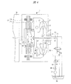
図2は本発明の一実施の形態であるトルクコンバータの要部拡大断面図である。図2に示すように、エンジン出力軸11を軸支するとともに発電モータ17を収容するモータハウジング20は、メインシャフト16を軸支するとともにトルクコンバータ1を収容するコンバータハウジング21に組み付けられている。コンバータハウジング21には、メインシャフト16とインペラハブ19との間に配置されるステータシャフト22が固定され、このステータシャフト22には一方向クラッチ23のインナーレース23aがスプライン結合されており、一方向クラッチ23のアウターレース23bにはステータ24が配置されている。
FIG. 2 is an enlarged cross-sectional view of a main part of the torque converter according to the embodiment of the present invention. As shown in FIG. 2, a
メインシャフト16の端部外周には、中空のタービンハブ25がスプライン結合されており、タービンハブ25はメインシャフト16と一体に回転する。タービンハブ25のフランジ部には、リベット26によりタービンランナ15のランナシェル27とロックアップダンパ28のばね座29とが連結されている。一方向クラッチ23とインペラハブ19との間、および一方向クラッチ23とタービンハブ25のフランジ部との間にはスラストベアリング30が配設されており、ランナシェル27およびロックアップダンパ28に伝達されるトルクは、タービンハブ25を介してメインシャフト16に伝達されることになる。
A
ロックアップダンパ28は、タービンハブ25に連結されるばね座29と、クラッチハブ31に連結されるばね座32と、円周方向に配置されて両ばね座29,32間を連結する複数のトーションスプリング33とを有している。クラッチハブ31は、タービンハブ25に嵌合する筒部31aを有し、この筒部31aにはばね座32が固定されている。また、クラッチハブ31は筒部31aから径方向外方に延びるディスク部31bと、このディスク部31bからエンジン出力軸11に向けて延びるドラム部31cとを有している。
The lock-
フロントカバー12はエンジン出力軸11に形成された取付孔34に取り付けられる軸部35が固定された内側円板部36と、その内側円板部36の外周部からポンプインペラ13に向けて軸方向に延びる筒状のドラム部37と、そのドラム部37から径方向に延びインペラシェル14との間でコンバータ室38を形成する外側円板部39とを有しており、外側円板部39の先端にはインペラシェル14に向けて延びてインペラシェル14に連結される外側円筒部40が設けられている。これより、エンジン10を駆動することによって、インペラシェル14にはフロントカバー12を介してエンジン出力が伝達されることになる。コンバータ室38には、インペラシェル14の外縁とランナシェル27の外縁との間に形成される隙間41を通って、作動油が流入するようになっている。
The
フロントカバー12のドラム部37はクラッチハブ31のドラム部31cと対向しており、ドラム部37の内側に配置された複数枚のドライブプレート42とドラム部31cの外側に配置された複数枚のドリブンプレート43が交互に積層されて、これらのプレート42,43によりロックアップクラッチ44が構成されている。ロックアップクラッチ44は内側円板部36とドラム部37とにより囲われるクラッチ室45に収容されている。このように、ロックアップクラッチ44を構成するドライブプレート42およびドリブンプレート43は多板クラッチとなっており、充分な受圧面積を確保し得ることから、動力伝達容量の増加を図ることができるとともに、エンジン10および発電モータ17のトルクを制御性良く伝達することができる。
The
フロントカバー12には、軸方向に移動自在にロックアップピストン46が装着され、このロックアップピストン46によりクラッチ室45とコンバータ室38とが仕切られている。フロントカバー12の内側には、タービンランナ15の配置方向に向けて延びる係止部材47が溶接されており、この係止部材47の所定の位置には当接部47aが突出して設けられており、ロックアップピストン46は、この当接部47aに当接する位置まで移動できるようになっている。ロックアップピストン46の外周溝には係止部材47と接触するシール部材48が装着されており、ロックアップピストン46の内周面はクラッチハブ31に装着されるシール部材49と接触している。つまり、クラッチ室45とコンバータ室38との間では相互に作動油が流れ込まないようになっている。
A
コンバータ室38には、インペラハブ19とステータシャフト22との間に形成されるコンバータ油路50と、ステータシャフト22とメインシャフト16との間に形成されるコンバータ油路51とが連通しており、これら2つのコンバータ油路50,51によってコンバータ室38への作動油の給排経路が構成されている。メインシャフト16の中空孔内部には、軸方向に延びるパイプ状の流路形成部材52が組み込まれており、この流路形成部材52によりメインシャフト16内にはクラッチ油路53,54が形成されている。このうち、クラッチ油路53はメインシャフト16およびタービンハブ25に形成された連通孔16a,25aを介してクラッチ室45に連通し、流路形成部材52の内側に形成されるクラッチ油路54は連通孔55を介してクラッチ室45に連通しており、これら2つのクラッチ油路53,54によってクラッチ室45への作動油の給排経路が構成されている。コンバータ室38に供給される作動油は、コンバータ室38内の部材を潤滑および冷却するとともにトルク伝達媒体として用いられるが、上述のロックアップピストン46によってクラッチ室45への流入は阻止されている。
The
ロックアップピストン46の作動は、コンバータ室38に供給される作動油の油圧とクラッチ室45に供給される作動油の油圧とを調圧する圧力調整手段により制御される。図1に示すように、コンバータ油路50とクラッチ油路54のそれぞれには圧力制御弁56,57が接続されており、調圧された作動油がコンバータ室38およびクラッチ室45のそれぞれに供給されるようになっている。図示する圧力制御弁56,57は開口状態を無段階に変化させることのできる比例電磁式圧力制御弁であり、例えば、油圧の温度変化分を補償して一定の油圧を供給することができる。オイルパン58に貯留され上述のオイルポンプ18により汲み上げられる作動油は、共通油路59に接続される流量制御弁60で流量を調整された後、コンバータ油路50およびクラッチ油路54のそれぞれに流れ込むようになっている。コンバータ油路51およびクラッチ油路53のそれぞれはオイルパン58に接続されており、トルクコンバータ1内部を還流する作動油の循環経路を構成している。この圧力調整手段によれば、クラッチ室45とコンバータ室38とにほぼ同圧の作動油を供給したり、クラッチ室45の圧力をコンバータ室38の圧力よりも低下させたりすることができる。
The operation of the lock-up
図2に示される場合にあっては、ロックアップクラッチ44は湿式の小径多板クラッチで構成されており、径方向寸法の短縮化が図られていることから、フロントカバー12のドラム部37の外周にはスペースを確保することができ、このスペースには発電モータ17が装着されるようになっている。
In the case shown in FIG. 2, the lock-up clutch 44 is a wet small-diameter multi-plate clutch, and the radial dimension is shortened. A space can be secured on the outer periphery, and the
エンジン出力軸11にはロータ支持部材61が固定されており、このロータ支持部材61はエンジン出力軸11にボルト62により締結される円板部61aと、フロントカバー12のドラム部37に沿って延びる円筒部61bと、フロントカバー12の外側円板部39に沿って延びる円板部61cとを有し、この円板部61cはフロントカバー12の外側円筒部40に締結されている。したがって、ロータ支持部材61とフロントカバー12はエンジン出力軸11により一体に回転駆動される。
A
円筒部61bには永久磁石を有するロータ17aが固定され、モータハウジング20の内壁面にはコイル63が巻き回されたステータ17bがロータ17aとの間で所定の隙間を形成するように固定されている。図示する場合には、発電モータ17はドラム部37の軸方向寸法とほぼ同程度の軸方向寸法に設定されており、ロックアップクラッチ44と発電モータ17とが軸方向にほぼ同一の位置となって径方向の内側と外側に配置されているので、動力伝達装置の軸方向寸法の短縮化が図られる。
A
次に、本発明のトルクコンバータ1の動力伝達経路について説明する。エンジン出力軸11のエンジン出力は、軸部35とロータ支持部材61を介してフロントカバー12に伝達される。発電モータ17をアシストモータとして作動させるときには、モータトルクはエンジン出力の補助トルクとしてロータ支持部材61を介してフロントカバー12に伝達される。フロントカバー12に伝達されるトルクはインペラシェル14に伝達され、ポンプインペラ13が回転することによって、コンバータ室38を満たしているオイルは、ステータ24介してタービンランナ15とポンプインペラ13の間を循環し、タービンランナ15を回転させる。タービンランナ15の回転はタービンハブ25を介してメインシャフト16へと伝達される。このとき、ポンプインペラ13とタービンランナ15との間でトルクの増幅作用が生じていれば、それに伴う反力がステータ24に負荷され、ステータ24は一方向クラッチ23により回転が阻止される。また、インペラシェル14に連結されるインペラハブ19に伝達されるトルクによりオイルポンプ18が駆動される。
Next, the power transmission path of the
このように、トルクコンバータ1の有するトルク増幅作用を利用して動力の伝達を行なう際には、ロックアップクラッチ44の締結は解除しておく必要がある。図3(A)はロックアップ解除制御の手順を示す説明図である。図示するように、このトルクコンバータにおいては、ロックアップ解除要求の有無を判断し(ステップS1)、解除要求があれば、圧力調整手段を構成する圧力制御弁56,57を制御して、コンバータ室38の圧力と同圧の作動油をクラッチ室45に供給する(ステップS2)。解除要求がなければ、解除制御はそのまま終了する。クラッチ室45とコンバータ室38とにほぼ同圧の作動油を供給すると、クラッチ室45の油圧とコンバータ室38の油圧との間に差圧は発生しないのでロックアップピストン46は作動しない。このとき、ドライブプレート42とドリブンプレート43との間にはクラッチ室45に供給される作動油が入り込み、ドライブプレート42とドリブンプレート43の間に滑りが生じてこれらは相互に離間することによって締結が解除される。
As described above, when the power is transmitted using the torque amplification function of the
エンジン回転数の増加に伴ってトルクコンバータ1の速度比が1に近づくと、ポンプインペラ13とタービンランナ15との間でのトルクの増幅作用はなくなる。このときは、作動油の滑りによる動力伝達ロスを避けるために、ロックアップクラッチ44を締結することによって、エンジン出力がメインシャフト16に直接伝達されるようにする。
When the speed ratio of the
図3(B)はロックアップ締結制御の手順を示す説明図である。図示するように、ロックアップ締結要求の有無を判断し(ステップS3)、締結要求があれば、コンバータ室38の圧力Pとロックアップ締結必要圧Ptとの比較判断を行なう(ステップS4)。このステップS4を必要とするのは、走行状況に応じてコンバータ室38の圧力Pをキャビティーションの発生を抑制し得る範囲に低下させておき、ロックアップ締結時にのみコンバータ室38の圧力Pを上げるようにする場合があるからである。ステップS4において圧力Pが必要圧Pt未満と判断されたときには、圧力制御弁56,57を制御してコンバータ室38の圧力Pを上昇させる(ステップS5)。ステップS4において、圧力Pが必要圧Pt以上であると判断されたときには、圧力制御弁56,57を制御して、クラッチ室45の圧力をコンバータ室の圧力よりも低下させる(ステップS6)。これにより、クラッチ室45の油圧とコンバータ室38の油圧との差圧により作動するロックアップピストン46は低圧のクラッチ室45側に移動し、ロックアップクラッチ44を押圧することによって、ロックアップクラッチ44を締結させる。
FIG. 3B is an explanatory diagram showing a procedure of lock-up fastening control. As shown in the figure, it is determined whether or not there is a lockup engagement request (step S3). If there is an engagement request, a comparison determination is made between the pressure P of the
このように、本発明のトルクコンバータ1によれば、クラッチ室45の圧力をコンバータ室38の圧力よりも低下させることでロックアップ締結を行なうことができ、クラッチ室45とコンバータ室38とにほぼ同圧の作動油を供給することでロックアップ締結の解除を行なうことができる。すなわち、一連のロックアップ制御において、クラッチ室45の圧力をコンバータ室38の圧力よりも高圧にする必要がなく、ロックアップクラッチ44の切り換えに必要とされる油圧の高圧化を防止することができる。加えて、クラッチ室45とコンバータ室38とは仕切られた構造となっているので、クラッチ室45とコンバータ室38との間に作動油の流れはなく、ロックアップピストン46の応答性を高めることができる。
As described above, according to the
ロックアップクラッチ44を完全に締結すればフロントカバー12とクラッチハブ31とは一体として回転するようになる。これにより、エンジン出力軸11のトルクは、フロントカバー12からロックアップクラッチ44を介してクラッチハブ31に伝達され、次いで、ロックアップダンパ28からタービンハブ25を介してメインシャフト16に伝達されるようになり、ポンプインペラ13およびタービンランナ15間の動力伝達ロスを避けることができる。エンジントルクの変動はロックアップダンパ28により吸収される。なお、走行状況に応じて、ドライブプレート42とドリブンプレート43とはスリップ状態で締結させることも可能である。
When the
図4は本発明の他の実施の形態であるトルクコンバータの全体構成を示すスケルトン図である。なお、図1に示すものと同一の部材には同一の番号が付されている。図示するように、クラッチ油路54には、クラッチ室45にコンバータ室38とほぼ同圧の作動油を供給する解除位置64aとクラッチ室45の作動油を吐出する締結位置64bとを有する電磁弁64が接続されている。この電磁弁64はコンバータ油路50に連通する共通油路59に接続されており、その共通油路59には圧力制御弁65と流量制御弁60とが接続されている。つまり、流量制御弁60により流量が調整され、圧力制御弁65により圧力が調整された作動油は、コンバータ油路50と電磁弁64が接続されるクラッチ油路54のそれぞれに流れ込むようになっている。
FIG. 4 is a skeleton diagram showing the overall configuration of a torque converter according to another embodiment of the present invention. In addition, the same number is attached | subjected to the member same as what is shown in FIG. As shown in the figure, the
図4に示す場合には、クラッチ室45内の作動油をオイルパン58に排出することによりクラッチ室45の圧力をコンバータ室38の圧力よりも低下させてロックアップラッチ44を締結させる。すなわち、ロックアップ解除要求があるときには、電磁弁64を解除位置64aに設定し、共通油路59を介してコンバータ室38とクラッチ室45にはほぼ同圧の作動油を供給する。これにより、ロックアップピストン46に作用する差圧は消滅し、ロックアップクラッチ44の締結は解除されることになる。一方、ロックアップ締結要求があるときには、電磁弁64を締結位置64bに設定すると、クラッチ室45はオイルパン58に連通状態となる。これにより、クラッチ室45の作動油は排出されるので、クラッチ室45の圧力はコンバータ室38の圧力よりも低下して差圧が発生し、差圧により作動するロックアップピストン46がロックアップクラッチ44を押圧することによってロックアップクラッチ44が締結されることになる。
In the case shown in FIG. 4, the hydraulic oil in the
このように、本発明のトルクコンバータ1によれば、ロックアップクラッチ44に作用する作動油の圧力は、クラッチ室44の作動油を排出することにより制御することができるので、ロックアップクラッチ44の切換制御を容易にすることができる。
As described above, according to the
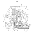
図5は本発明の他の実施の形態であるトルクコンバータの要部拡大断面図であり、図2に示される部材と同一の部材には同一の番号が付されている。図示する場合にあっては、ロックアップピストン46bは、フロントカバー12の外側円板部39に沿って径方向外方に向けて延びる大径受圧部46cを有している。これにより、ロックアップピストン46bの受圧面積が拡大されるので、ロックアップクラッチ44に対する押し力を高めることができる。さらに、ロックアップクラッチ44の押し力を高めることで、図示するように、ドライブプレート42およびドリブンプレート43の装着枚数を減らしても十分な締結力を確保することができるようになる。これによって、部品点数の削減やロックアップクラッチの小型化を図ることができる。また、クラッチハブ31dを、図2に示すような径方向外方に延びるディスク部31bを設けずに円筒形状にすることもでき、その場合にはロックアップクラッチ44の内径を小さくして径方向寸法を大きく設定することができる。
FIG. 5 is an enlarged cross-sectional view of a main part of a torque converter according to another embodiment of the present invention, and the same members as those shown in FIG. In the case illustrated, the lock-up
図6は本発明の他の実施の形態であるトルクコンバータの要部拡大断面図であり、図5に示される部材と同一の部材には同一の番号が付されている。図示する場合にあっては、フロントカバー12のドラム部37には、ロックアップピストン46bに当接して、ロックアップクラッチ44の締結を解除する方向に付勢力を及ぼす弾性体66が設けられている。クラッチ室45とコンバータ室38とにほぼ同圧の作動油を供給する場合にはロックアップピストン46bは差圧により作動することはないが、この場合でも上述の弾性体66の付勢力によってロックアップピストン46bはロックアップクラッチ44の締結を解除する方向に作動するので、ロックアップピストン46bがロックアップクラッチ44と干渉しあうことがなくなり、確実にロックアップクラッチ44の締結を解除することができる。
FIG. 6 is an enlarged cross-sectional view of a main part of a torque converter according to another embodiment of the present invention, and the same members as those shown in FIG. In the illustrated case, the
本発明は前記実施の形態に限定されるものではなく、その要旨を逸脱しない範囲で種々変更可能である。たとえば、上述のロックアップクラッチ44は多板クラッチとなっているがこれを単板クラッチで構成するようにしても良い。図示する実施の形態にあっては、フロントカバー12のドラム部37の外側に発電モータ17を装着するようにし、このトルクコンバータ1はハイブリッド車両に搭載されるが、発電モータ17を装着しない車両に本発明のトルクコンバータを用いることも可能である。
The present invention is not limited to the above-described embodiment, and various modifications can be made without departing from the scope of the invention. For example, although the above-described lockup clutch 44 is a multi-plate clutch, it may be a single-plate clutch. In the illustrated embodiment, the
1 トルクコンバータ
11 エンジン出力軸
12 フロントカバー
13 ポンプインペラ
14 インペラシェル
15 タービンランナ
16 メインシャフト
27 ランナシェル
36 内側円板部
37 ドラム部
38 コンバータ室
39 外側円板部
42 ドライブプレート
43 ドリブンプレート
44 ロックアップクラッチ
45 クラッチ室
46,46b ロックアップピストン
50,51 コンバータ油路
53,54 クラッチ油路
56,57,65 圧力制御弁
59 共通油路
60 流量制御弁
64 電磁弁
66 弾性体
P コンバータ室の圧力
Pt ロックアップ締結必要圧
DESCRIPTION OF
Claims (3)
前記エンジン出力軸が取り付けられる内側円板部と、当該内側円板部から前記ポンプインペラに向けて軸方向に延びる筒状のドラム部と、当該ドラム部から径方向に延び前記インペラシェルとの間でコンバータ室を形成する外側円板部とを有するフロントカバーと、
前記ドラム部に装着されるドライブプレートと、前記メインシャフトに連結されたクラッチハブに装着されるドリブンプレートとにより構成されるロックアップクラッチと、
前記フロントカバーに軸方向に移動自在に装着され、前記ロックアップクラッチを収容するクラッチ室と前記コンバータ室とを仕切り、相互に作動油の流入を阻止するロックアップピストンと、
前記ロックアップクラッチの外周に配設された発電モータと、
前記ロックアップクラッチの係合を解除する際に前記クラッチ室と前記コンバータ室とにほぼ同圧の作動油を供給し、前記ロックアップクラッチを係合させる際に前記クラッチ室の圧力を前記コンバータ室の圧力よりも低下させる圧力調整手段とを有し、
前記圧力調整手段は前記クラッチ室に連通するクラッチ油路に接続される電磁弁を有し、前記クラッチ室に前記コンバータ室とほぼ同圧の作動油を供給する解除位置と前記クラッチ室の作動油を排出する締結位置とに切り換えることを特徴とするトルクコンバータ。 A torque converter having an impeller shell provided with a pump impeller and driven by an engine output shaft, and a turbine runner coupled to the main shaft so as to face the pump impeller, amplifying the engine output and transmitting it to the main shaft Because
Between the inner disc portion to which the engine output shaft is attached, a cylindrical drum portion extending in the axial direction from the inner disc portion toward the pump impeller, and the impeller shell extending in the radial direction from the drum portion A front cover having an outer disk portion forming a converter chamber with,
A lockup clutch comprising a drive plate attached to the drum portion and a driven plate attached to a clutch hub connected to the main shaft;
A lockup piston that is mounted on the front cover so as to be movable in the axial direction, partitions the clutch chamber that houses the lockup clutch and the converter chamber, and prevents the inflow of hydraulic oil from each other;
A generator motor disposed on the outer periphery of the lock-up clutch;
When releasing the engagement of the lock-up clutch, substantially the same hydraulic fluid is supplied to the clutch chamber and the converter chamber, and when the lock-up clutch is engaged, the pressure in the clutch chamber is changed to the converter chamber. have a pressure regulating means for reducing than the pressure of,
The pressure adjusting means has a solenoid valve connected to a clutch oil passage communicating with the clutch chamber, and a release position for supplying the clutch chamber with hydraulic oil having substantially the same pressure as the converter chamber, and the hydraulic oil in the clutch chamber. a torque converter, wherein Rukoto switched between engaged position for discharging.
3. The torque converter according to claim 1 , wherein the lock-up piston extends to a position overlapping with the generator motor in a radial direction.
Priority Applications (2)
| Application Number | Priority Date | Filing Date | Title |
|---|---|---|---|
| JP2004010259A JP4623973B2 (en) | 2004-01-19 | 2004-01-19 | Torque converter |
| US11/036,355 US7234577B2 (en) | 2004-01-19 | 2005-01-18 | Torque converter |
Applications Claiming Priority (1)
| Application Number | Priority Date | Filing Date | Title |
|---|---|---|---|
| JP2004010259A JP4623973B2 (en) | 2004-01-19 | 2004-01-19 | Torque converter |
Publications (3)
| Publication Number | Publication Date |
|---|---|
| JP2005201402A JP2005201402A (en) | 2005-07-28 |
| JP2005201402A5 JP2005201402A5 (en) | 2007-02-08 |
| JP4623973B2 true JP4623973B2 (en) | 2011-02-02 |
Family
ID=34747243
Family Applications (1)
| Application Number | Title | Priority Date | Filing Date |
|---|---|---|---|
| JP2004010259A Expired - Fee Related JP4623973B2 (en) | 2004-01-19 | 2004-01-19 | Torque converter |
Country Status (2)
| Country | Link |
|---|---|
| US (1) | US7234577B2 (en) |
| JP (1) | JP4623973B2 (en) |
Families Citing this family (29)
| Publication number | Priority date | Publication date | Assignee | Title |
|---|---|---|---|---|
| JP4935006B2 (en) * | 2005-07-06 | 2012-05-23 | アイシン・エィ・ダブリュ株式会社 | Fluid transmission device |
| US20070251788A1 (en) * | 2006-05-01 | 2007-11-01 | Luk Lamellen Und Kupplungsbau Beteiligungs Kg | Drive plate and seal for a torque converter |
| US8919509B2 (en) * | 2006-12-18 | 2014-12-30 | Schaeffler Technologies AG & Co. KG | Torque transfer device |
| DE102007055145B4 (en) * | 2006-12-18 | 2017-03-02 | Schaeffler Technologies AG & Co. KG | Torque transfer device |
| US9133936B2 (en) * | 2006-12-27 | 2015-09-15 | Schaeffler Technologies AG & Co. KG | Seal retainer device and power transmission unit with seal retainer device |
| DE102007010359A1 (en) | 2007-03-03 | 2008-09-04 | Zf Friedrichshafen Ag | Vehicle clutch has sealing ring mounted on piston which engages clutch plates, ring being mounted in groove on outside of piston which is dimensioned according to stroke of piston |
| US7971694B2 (en) * | 2007-04-20 | 2011-07-05 | Ati Performance Products, Inc. | Automatic transmission and shaft system therefor |
| DE102008031955B4 (en) * | 2007-07-31 | 2018-12-20 | Schaeffler Technologies AG & Co. KG | Torque converter with piston-centered clutch plate |
| DE102009040367A1 (en) * | 2008-09-26 | 2010-04-08 | Luk Lamellen Und Kupplungsbau Beteiligungs Kg | Combined power transmission and drive unit for use in hybrid systems and hybrid systems |
| JP2010120543A (en) * | 2008-11-20 | 2010-06-03 | Toyota Motor Corp | Driving device for vehicle |
| DE102009045610A1 (en) * | 2009-10-13 | 2011-05-05 | Zf Friedrichshafen Ag | Wet-running clutch arrangement |
| DE102011109702A1 (en) * | 2011-08-06 | 2013-02-07 | Daimler Ag | Torque converter device for a motor vehicle |
| US9365103B2 (en) * | 2011-10-11 | 2016-06-14 | Ford Global Technologies, Llc | Torsion damper for hybrid electric transmission |
| US9086126B2 (en) * | 2011-10-11 | 2015-07-21 | Ford Global Technologies, Llc | Modular hybrid transmission |
| CN103158529B (en) * | 2011-12-14 | 2017-09-12 | 福特全球技术公司 | Torsional damper for hybrid electric speed changer |
| US9157495B2 (en) * | 2013-10-24 | 2015-10-13 | Ford Global Technologies, Llc | Torque converter having integrated flex plate for hybrid electric vehicle |
| JP6027044B2 (en) * | 2014-03-14 | 2016-11-16 | トヨタ自動車株式会社 | Vehicle drive device and assembly method thereof |
| DE112015004686T5 (en) * | 2014-10-16 | 2017-07-06 | Schaeffler Technologies AG & Co. KG | Hybrid drive module with optimized electric motor attachment |
| JP2016217436A (en) * | 2015-05-19 | 2016-12-22 | 本田技研工業株式会社 | Torque converter device |
| US10948062B2 (en) * | 2017-11-02 | 2021-03-16 | Schaeffler Technologies AG & Co. KG | Torque converter for modular hybrid transmission including coast engagement structure |
| JP7043312B2 (en) * | 2018-03-28 | 2022-03-29 | 株式会社エクセディ | Vehicle drive |
| DE102018220396A1 (en) * | 2018-11-28 | 2020-05-28 | Zf Friedrichshafen Ag | Hydraulic system with a hydrodynamic torque converter |
| US10792991B2 (en) * | 2018-12-05 | 2020-10-06 | Schaeffler Technologies AG & Co. KG | Hybrid module including torque converter having a stator friction brake |
| US11511614B2 (en) * | 2019-06-10 | 2022-11-29 | Schaeffler Technologies AG & Co. KG | Rotor carrier connection |
| US11124056B2 (en) | 2019-09-09 | 2021-09-21 | Exedy Corporation | Vehicle drive apparatus |
| US11351855B2 (en) * | 2020-05-15 | 2022-06-07 | Schaeffler Technologies AG & Co. KG | Multi-mode hybrid module |
| JP2022044923A (en) | 2020-09-08 | 2022-03-18 | 株式会社エクセディ | Drive device |
| JP2022044922A (en) | 2020-09-08 | 2022-03-18 | 株式会社エクセディ | Drive device |
| JP2022044920A (en) | 2020-09-08 | 2022-03-18 | 株式会社エクセディ | Drive device |
Citations (4)
| Publication number | Priority date | Publication date | Assignee | Title |
|---|---|---|---|---|
| JPH0573351U (en) * | 1992-03-13 | 1993-10-08 | ジャトコ株式会社 | Lockup device for torque converter |
| JP2000179644A (en) * | 1998-12-18 | 2000-06-27 | Toyota Motor Corp | Driving device for vehicle |
| JP2001132818A (en) * | 1999-08-26 | 2001-05-18 | Honda Motor Co Ltd | Torque converter with lock-up mechanism |
| JP2002195376A (en) * | 2000-12-25 | 2002-07-10 | Aisin Aw Co Ltd | Manufacturing method for driving device for hybrid vehicle |
Family Cites Families (14)
| Publication number | Priority date | Publication date | Assignee | Title |
|---|---|---|---|---|
| US3001415A (en) * | 1954-05-11 | 1961-09-26 | Borg Warner | Transmission |
| JPS5517258B2 (en) * | 1971-10-12 | 1980-05-10 | ||
| JPS596462A (en) * | 1982-07-01 | 1984-01-13 | Honda Motor Co Ltd | Automatic transmission for vehicle |
| JPH02240443A (en) * | 1989-03-10 | 1990-09-25 | Mazda Motor Corp | Lookup structure for automatic transmission |
| US4951788A (en) * | 1989-06-28 | 1990-08-28 | Ford Motor Company | Torque converter multiplate bypass clutch |
| JPH0351575A (en) * | 1989-07-18 | 1991-03-05 | Nissan Motor Co Ltd | Fluid transmission device equipped with lock-up clutch |
| US5330038A (en) * | 1993-08-27 | 1994-07-19 | General Motors Corporation | Torque converter clutch |
| JPH07119827A (en) * | 1993-10-20 | 1995-05-12 | Aisin Seiki Co Ltd | Control device for fluid coupling with direct-coupled clutch |
| ES2139487B1 (en) * | 1995-10-04 | 2000-09-16 | Fichtel & Sachs Ag | TRANSITION CLUTCH OF A HYDRODYNAMIC TORQUE CONVERTER. |
| JP3854661B2 (en) * | 1996-05-29 | 2006-12-06 | 株式会社エクセディ | Torque converter with lock-up device |
| JP4085558B2 (en) | 1999-10-01 | 2008-05-14 | アイシン・エィ・ダブリュ株式会社 | Hybrid vehicle drive system |
| JP3539313B2 (en) * | 1999-10-18 | 2004-07-07 | 日産自動車株式会社 | Lockup control device for torque converter |
| JP2003063264A (en) | 2001-08-24 | 2003-03-05 | Honda Motor Co Ltd | Power transmission device for hybrid vehicle |
| JP4568496B2 (en) * | 2003-12-18 | 2010-10-27 | 富士重工業株式会社 | Torque converter |
-
2004
- 2004-01-19 JP JP2004010259A patent/JP4623973B2/en not_active Expired - Fee Related
-
2005
- 2005-01-18 US US11/036,355 patent/US7234577B2/en not_active Expired - Fee Related
Patent Citations (4)
| Publication number | Priority date | Publication date | Assignee | Title |
|---|---|---|---|---|
| JPH0573351U (en) * | 1992-03-13 | 1993-10-08 | ジャトコ株式会社 | Lockup device for torque converter |
| JP2000179644A (en) * | 1998-12-18 | 2000-06-27 | Toyota Motor Corp | Driving device for vehicle |
| JP2001132818A (en) * | 1999-08-26 | 2001-05-18 | Honda Motor Co Ltd | Torque converter with lock-up mechanism |
| JP2002195376A (en) * | 2000-12-25 | 2002-07-10 | Aisin Aw Co Ltd | Manufacturing method for driving device for hybrid vehicle |
Also Published As
| Publication number | Publication date |
|---|---|
| JP2005201402A (en) | 2005-07-28 |
| US7234577B2 (en) | 2007-06-26 |
| US20050155831A1 (en) | 2005-07-21 |
Similar Documents
| Publication | Publication Date | Title |
|---|---|---|
| JP4623973B2 (en) | Torque converter | |
| JP4568496B2 (en) | Torque converter | |
| JP5149974B2 (en) | Vehicle drive device | |
| US8545366B2 (en) | Shiftable clutch device, particularly friction wet clutch, drive train for a hybrid system and method for operating the drive train and vehicle including the drive train | |
| JP4944624B2 (en) | Fluid transmission device | |
| JP3447141B2 (en) | Torque converter | |
| US7264101B2 (en) | Start-up clutch and torsional-vibration damper assembly | |
| JP5222979B2 (en) | Torque converter lockup device | |
| JP5627577B2 (en) | Switchable clutch device in disk structure | |
| EP1903258B1 (en) | Torque converter | |
| JP5401697B2 (en) | Multifunction torque converter with sealed impeller clutch providing chamber and method of forming and operating a multifunction torque converter | |
| JP5072770B2 (en) | Torque converter | |
| JP4000152B2 (en) | Clutch device | |
| JP5472486B2 (en) | Power transmission device for vehicle | |
| WO2010021243A1 (en) | Torque converter | |
| JP2009047272A (en) | Fluid gearing with lock-up clutch | |
| JPH09229090A (en) | Start clutch | |
| JP2003063263A (en) | Power transmission device for hybrid vehicle | |
| EP0770797B1 (en) | Hydraulic power transmission | |
| JPH08270751A (en) | Torque converter | |
| US20210246974A1 (en) | Electric machine with fluid coupling | |
| JP2013072552A (en) | Fluid transmission device | |
| JP7002986B2 (en) | Vehicle torque converter | |
| JP4517634B2 (en) | Fluid coupling | |
| JP3709885B2 (en) | Power transmission device for hybrid vehicle |
Legal Events
| Date | Code | Title | Description |
|---|---|---|---|
| A521 | Request for written amendment filed |
Free format text: JAPANESE INTERMEDIATE CODE: A523 Effective date: 20061218 |
|
| A621 | Written request for application examination |
Free format text: JAPANESE INTERMEDIATE CODE: A621 Effective date: 20061218 |
|
| A977 | Report on retrieval |
Free format text: JAPANESE INTERMEDIATE CODE: A971007 Effective date: 20090630 |
|
| A131 | Notification of reasons for refusal |
Free format text: JAPANESE INTERMEDIATE CODE: A131 Effective date: 20091013 |
|
| A521 | Request for written amendment filed |
Free format text: JAPANESE INTERMEDIATE CODE: A523 Effective date: 20091203 |
|
| A02 | Decision of refusal |
Free format text: JAPANESE INTERMEDIATE CODE: A02 Effective date: 20100615 |
|
| A521 | Request for written amendment filed |
Free format text: JAPANESE INTERMEDIATE CODE: A523 Effective date: 20100907 |
|
| A911 | Transfer to examiner for re-examination before appeal (zenchi) |
Free format text: JAPANESE INTERMEDIATE CODE: A911 Effective date: 20100924 |
|
| TRDD | Decision of grant or rejection written | ||
| A01 | Written decision to grant a patent or to grant a registration (utility model) |
Free format text: JAPANESE INTERMEDIATE CODE: A01 Effective date: 20101019 |
|
| A01 | Written decision to grant a patent or to grant a registration (utility model) |
Free format text: JAPANESE INTERMEDIATE CODE: A01 |
|
| A61 | First payment of annual fees (during grant procedure) |
Free format text: JAPANESE INTERMEDIATE CODE: A61 Effective date: 20101102 |
|
| R150 | Certificate of patent or registration of utility model |
Ref document number: 4623973 Country of ref document: JP Free format text: JAPANESE INTERMEDIATE CODE: R150 Free format text: JAPANESE INTERMEDIATE CODE: R150 |
|
| FPAY | Renewal fee payment (event date is renewal date of database) |
Free format text: PAYMENT UNTIL: 20131112 Year of fee payment: 3 |
|
| R250 | Receipt of annual fees |
Free format text: JAPANESE INTERMEDIATE CODE: R250 |
|
| S531 | Written request for registration of change of domicile |
Free format text: JAPANESE INTERMEDIATE CODE: R313531 |
|
| R350 | Written notification of registration of transfer |
Free format text: JAPANESE INTERMEDIATE CODE: R350 |
|
| R250 | Receipt of annual fees |
Free format text: JAPANESE INTERMEDIATE CODE: R250 |
|
| R250 | Receipt of annual fees |
Free format text: JAPANESE INTERMEDIATE CODE: R250 |
|
| R250 | Receipt of annual fees |
Free format text: JAPANESE INTERMEDIATE CODE: R250 |
|
| S533 | Written request for registration of change of name |
Free format text: JAPANESE INTERMEDIATE CODE: R313533 |
|
| R350 | Written notification of registration of transfer |
Free format text: JAPANESE INTERMEDIATE CODE: R350 |
|
| R250 | Receipt of annual fees |
Free format text: JAPANESE INTERMEDIATE CODE: R250 |
|
| R250 | Receipt of annual fees |
Free format text: JAPANESE INTERMEDIATE CODE: R250 |
|
| R250 | Receipt of annual fees |
Free format text: JAPANESE INTERMEDIATE CODE: R250 |
|
| R250 | Receipt of annual fees |
Free format text: JAPANESE INTERMEDIATE CODE: R250 |
|
| R250 | Receipt of annual fees |
Free format text: JAPANESE INTERMEDIATE CODE: R250 |
|
| LAPS | Cancellation because of no payment of annual fees |