JP4623313B2 - Threshing device - Google Patents

Threshing device Download PDF

Info

Publication number
JP4623313B2
JP4623313B2 JP2006214356A JP2006214356A JP4623313B2 JP 4623313 B2 JP4623313 B2 JP 4623313B2 JP 2006214356 A JP2006214356 A JP 2006214356A JP 2006214356 A JP2006214356 A JP 2006214356A JP 4623313 B2 JP4623313 B2 JP 4623313B2
Authority
JP
Japan
Prior art keywords
processing
threshing
cylinder
grains
grain
Prior art date
Legal status (The legal status is an assumption and is not a legal conclusion. Google has not performed a legal analysis and makes no representation as to the accuracy of the status listed.)
Expired - Fee Related
Application number
JP2006214356A
Other languages
Japanese (ja)
Other versions
JP2008035782A5 (en
JP2008035782A (en
Inventor
久幸 里路
Current Assignee (The listed assignees may be inaccurate. Google has not performed a legal analysis and makes no representation or warranty as to the accuracy of the list.)
Iseki and Co Ltd
Original Assignee
Iseki and Co Ltd
Priority date (The priority date is an assumption and is not a legal conclusion. Google has not performed a legal analysis and makes no representation as to the accuracy of the date listed.)
Filing date
Publication date
Application filed by Iseki and Co Ltd filed Critical Iseki and Co Ltd
Priority to JP2006214356A priority Critical patent/JP4623313B2/en
Publication of JP2008035782A publication Critical patent/JP2008035782A/en
Publication of JP2008035782A5 publication Critical patent/JP2008035782A5/ja
Application granted granted Critical
Publication of JP4623313B2 publication Critical patent/JP4623313B2/en
Expired - Fee Related legal-status Critical Current
Anticipated expiration legal-status Critical

Links

Images

Description

本発明は、脱穀装置に係るものである。   The present invention relates to a threshing apparatus.

従来、脱穀室の側部後方に排塵処理室を設け、脱穀室の側方に扱胴の軸心と平行で外周に処理歯を有する処理胴を有する二番処理室を設け、該二番処理室の後部は排塵処理室の下方に位置させた構成は、公知である(特許文献1)
特開2005−110689号公報
Conventionally, a dust removal processing chamber is provided behind the threshing chamber side, and a second processing chamber having a processing cylinder having processing teeth on the outer periphery parallel to the axis of the handling cylinder is provided on the side of the threshing chamber. A configuration in which the rear portion of the processing chamber is positioned below the dust processing chamber is known (Patent Document 1).
Japanese Patent Laid-Open No. 2005-110589

前記公知例は、二番コンベアで戻された二番物および排塵処理室から落下する穀粒を、二番処理装置の二番処理胴により揺動選別棚の始端部に戻して再処理する構成であるが、脱穀済み穀稈(排藁)中に刺さり込んだ穀粒は、そのまま、排藁と共に機外に排出されてしまうので、当業者が「四番物」と呼ぶ穀粒が機外に排出されて脱穀のロスになるという課題がある。
本願は、四番物のロスを減少させて、脱穀効率を向上させるようにしたものである。
In the known example, the second product returned by the second conveyor and the grains falling from the dust removal processing chamber are returned to the starting end of the swing sorting shelf by the second processing cylinder of the second processing device and reprocessed. Although it is a structure, since the grain stabbed in the threshed grain basket (excretion) will be discharged out of the machine with the excretion as it is, a grain called a “fourth thing” by those skilled in the art There is a problem that it is discharged outside and becomes a loss of threshing.
In the present application, the loss of the fourth item is reduced to improve the threshing efficiency.

請求項1記載の発明は、上部に扱胴(11)を軸装して、穀稈供給搬送装置(13)により搬送される穀稈を脱穀する脱穀室(12)を設け、脱穀室(12)の扱網(18)の下方に、送風唐箕からの送風と揺動により穀粒とその他の処理物を風選する揺動選別棚(25)により構成した揺動選別装置(26)を設け、前記脱穀室(12)の後方には処理歯(39)を設けた四番処理胴(38)を軸装して搬送穀稈中に刺さり込んでいる刺さり粒を落下処理させる四番処理装置(36)を設け、脱穀室(12)の後側側部には、扱胴(11)の軸心と略平行で外周に処理歯(42)を有する排塵処理胴(41)を軸装し、脱穀室(12)と排塵連通口(44)により連通する排塵処理室(40)を設け、背面視、前記四番処理胴(38)と排塵処理胴(41)との間に、四番処理胴(38)と排塵処理胴(41)から落下する穀粒を回収して、前記揺動選別棚(25)の始端部に搬送する三番処理装置(55)を設けた脱穀装置としたものであり、穀稈供給搬送装置13により搬送された穀稈は、脱穀室12内に供給され、回転する扱胴11により脱穀され、脱穀された脱穀物(被処理物)は扱網18から下方の揺動選別棚25に落下し、揺動選別棚25の揺動と送風唐箕19の送風により選別され、穀粒は一番コンベア34から回収される。
また、穀稈供給搬送装置13により搬送された搬送穀稈は、脱穀室12で脱穀処理されると、脱穀室12の後方に設けた四番処理装置36で、回転する四番処理胴38の処理歯39により搬送穀稈中に刺さり込んでいる刺さり粒を落下させ、落下した穀粒は四番処理物受け板59により三番処理装置55の受樋56に誘導されて回収される。
また、脱穀室12で脱穀された脱穀物のうち、扱網18より落下しない脱穀物の一部は排塵連通口44から排塵処理室40に入り、排塵処理室40内で回転する排塵処理胴41の処理歯42により攪拌処理される
して、三番処理装置55は四番処理胴38と排塵処理胴41の間に設けられているので、四番処理装置36と排塵処理室40から落下した穀粒は、四番処理物受け板59により三番処理装置55の受樋56に入り、三番処理胴57により揺動選別棚25の始端部に戻されて再処理される。
請求項2記載の発明は、前記三番処理装置55は、扱胴11の軸芯と平行方向の受樋56を設け、受樋56内に外周に螺旋状の処理歯58を有する三番処理胴57を設けて構成し、前記三番処理装置55の受樋56は前記四番処理胴38の下方に設けた四番処理物受け板59と接続した脱穀装置としたものであり、揺動選別棚25の中間部上面には、脱穀室12から落下した大量の藁屑が移動中であり、この藁屑中に穀粒が落下しても、そのまま揺動選別棚25により機外に排出されて選別ロスとなってしまうが、四番処理胴38により藁屑から分離した穀粒は四番処理胴38の下方の四番処理物受け板59に落下し、四番処理物受け板59に落下した穀粒は四番処理物受け板59に接続された受樋56に入って回収され、三番処理胴57により藁屑発生の少ない揺動選別棚25の始端部に戻されて再処理される。
請求項3記載の発明は、前記穀稈供給搬送装置13の供給搬送チェン14の終端には、排藁搬送装置65の排藁搬送チェン66の始端部を臨ませ、排藁搬送装置65の下方には落下した刺さり粒を誘導する刺さり粒回収板67を設け、該刺さり粒回収板67の前端は四番処理物受け板59の後端を接続し、該刺さり粒回収板67は前記四番処理物受け板59と一体状に設けた脱穀装置としたものであり、穀稈供給搬送装置13により搬送された搬送穀稈中に刺さり込んでいる刺さり粒は、四番処理胴38の処理歯39により四番処理物受け板59に落下させて、四番処理物受け板59から三番処理装置55の受樋56に誘導して回収し、排藁搬送装置65により搬送中の排藁中より落下した刺さり粒は、刺さり粒回収板67に落下させて、刺さり粒回収板67から三番処理装置55の受樋56に誘導して回収される。
したがって、穀稈供給搬送装置13から排藁搬送装置65に亘って搬送される排藁を含む搬送穀稈中に刺さり込んでいる刺さり粒は、四番処理物受け板59および刺さり粒回収板67上に落下して、三番処理装置55の受樋56に誘導して回収され、回収のロスを減少させる。
請求項4記載の発明は、前記刺さり粒回収板67の穀稈供給搬送装置13側の側縁は、平面視、一部切り欠いて排藁搬送装置65の排藁搬送チェン66と略平行となるように配置した脱穀装置としたものであり、搬送中の排藁の穂先側から落下する穀粒(刺さり粒)は、穂先の移動軌跡の下方に沿って位置する刺さり粒回収板67上に落下して三番処理装置55の受樋56に回収され、排藁の株元側の移動軌跡下方は開放しているから、搬送中の排藁から落下する藁屑はそのまま揺動選別棚25に落下して機外に排出され、刺さり粒回収板67経由で藁屑を三番処理装置55に回収しないようにして、再処理効率の負荷を減少させる。
The invention according to claim 1 is provided with a threshing chamber (12) for attaching a handling cylinder (11) to the upper portion and threshing the culm conveyed by the cereal supply and transport device (13). ) Is provided with a swing sorting device (26) constituted by a swing sorting shelf (25) for wind-selecting grains and other processed materials by blowing and swinging from the blower tang. A fourth processing device is provided with a fourth processing cylinder (38) provided with processing teeth (39) behind the threshing chamber (12) to drop the stabbed grains that have been inserted into the transporting cereal. (36) is provided, and on the rear side portion of the threshing chamber (12), a dust exhausting cylinder (41) having a processing tooth (42) on the outer periphery and substantially parallel to the axis of the handling cylinder (11) is axially mounted. and, exhaust threshing chamber (12) dust-exhaust process chamber communicating with dust-exhaust communication port (44) provided (40), rear view, the fourth wheel processing cylinder (38) The grains falling from the fourth processing cylinder (38) and the dust removal processing cylinder (41) are collected between the processing cylinder (41) and conveyed to the starting end of the swing sorting shelf (25). The threshing device provided with the number processing device (55) is supplied to the threshing chamber 12 and threshed by the rotating handling cylinder 11 and threshed. The cereals (objects to be treated) fall from the handling net 18 to the lower swing sorting shelf 25 and are sorted by swinging the swing sorting shelf 25 and blowing air from the blower 19, and the grain is first fed from the conveyor 34. To be recovered.
In addition, when the cereals conveyed by the cereal supply and transfer device 13 are threshed in the threshing chamber 12, the fourth processing device 36 provided at the rear of the threshing chamber 12 is used to rotate the fourth processing cylinder 38. The treated teeth 39 drop the stabbed grains that have been stabbed into the transported culm, and the dropped grains are guided and collected by the fourth processed material receiving plate 59 to the receiving bowl 56 of the third processing device 55.
Further, of the threshing that has been threshed in the threshing chamber 12, a part of the threshing that does not fall from the handling net 18 enters the dust disposal chamber 40 through the dust communication port 44 and rotates in the dust disposal chamber 40. Agitation processing is performed by the processing teeth 42 of the dust processing cylinder 41 .
Their to, since third processor 55 is provided between the fourth wheel processing cylinder 38 and the dust-exhaust processor body 41, grains dropped from fourth wheel processor 36 and dust-exhaust processing chamber 40, fourth wheel The processed material receiving plate 59 enters the receiving bowl 56 of the third processing device 55, and the third processing cylinder 57 returns to the starting end portion of the swing sorting shelf 25 for reprocessing.
According to a second aspect of the present invention, the third processing device 55 is provided with a receiving hook 56 in a direction parallel to the axis of the handling cylinder 11 and has a spiral processing tooth 58 in the outer periphery thereof. A barrel 57 is provided, and a receiving trough 56 of the third processing device 55 is a threshing device connected to a fourth processed material receiving plate 59 provided below the fourth processing barrel 38, and swings. A large amount of sawdust dropped from the threshing chamber 12 is moving on the upper surface of the middle part of the sorting shelf 25, and even if grains fall into this sawdust, it is discharged out of the machine as it is by the swing sorting shelf 25. However, the grain separated from the sawdust by the fourth processing cylinder 38 falls to the fourth processing object receiving plate 59 below the fourth processing cylinder 38, and the fourth processing object receiving plate 59. The grain that has fallen into the No. 4 processing object receiving plate 59 is collected in the receiving bowl 56 and collected in the No. 3 processing cylinder 57. It returned to the starting end of Riwarakuzu generating less swinging sorting shelf 25 is reprocessed.
According to a third aspect of the present invention, the end of the supply and transport chain 14 of the grain supply and transfer device 13 faces the start end of the discharge and transfer chain 66 of the discharge and transfer device 65. Is provided with a stab particle collection plate 67 for guiding the fallen stab particles, the front end of the stab particle collection plate 67 is connected to the rear end of the fourth processed material receiving plate 59, and the stab particle collection plate 67 is the fourth. The threshing device provided integrally with the processed material receiving plate 59 is used, and the stabbed grains stabbed in the transported cocoon transported by the cereal supply and transport device 13 are treated teeth of the fourth processing barrel 38. 39 is dropped onto the fourth processed material receiving plate 59 and guided to the receiving tube 56 of the third processing device 55 from the fourth processed material receiving plate 59 and recovered, and is being discharged by the discharging and conveying device 65. The fallen stabbed grains are dropped on the stabbed grain collection plate 67 and stabbed. It recovered from Ritsubu collecting plate 67 to guide the 受 56 of third processing device 55.
Therefore, the stab grains that have been stabbed into the transported cereal including the sewage that is transported from the cereal supply and transfer device 13 to the evacuation and transport device 65 are the fourth processed material receiving plate 59 and the stab particle recovery plate 67. It falls to the top and is guided to the receiving rod 56 of the third processing unit 55 to be recovered, thereby reducing the recovery loss.
According to a fourth aspect of the present invention, the side edge of the stabbed grain collection plate 67 on the side of the cereal supply and transport device 13 is partially cut away in plan view and substantially parallel to the sewage transport chain 66 of the sewage transport device 65. The threshing device arranged in such a way that the grains (stabbed grains) that fall from the tip side of the waste being transported are placed on the stabbed grain collection plate 67 positioned along the lower part of the movement trajectory of the tip. Since it falls and is collected in the receptacle 56 of the third processing unit 55 and opened below the movement trajectory on the stock source side of the waste, the waste falling from the waste being transported remains as it is. The waste is not discharged to the third processing device 55 via the stab particle collection plate 67, and the load of reprocessing efficiency is reduced.

請求項1記載の発明では、三番処理装置55は四番処理胴38と排塵処理胴41の間に設けられているので、四番処理装置36と排塵処理室40から落下した穀粒を三番処理装置55により揺動選別棚25の始端部に戻して再処理でき、脱穀ロスを減少させることができ、また、脱穀装置全体の高さを低くして、コンパクトに構成できる。
請求項2記載の発明では、四番処理装置36の四番処理胴38により搬送穀稈中の刺さり粒を、藁屑を大量に発生させずに四番処理物受け板59に落下させるので、脱穀負荷をあまり増やさずに四番物の回収効率を向上させることができる。
請求項3記載の発明では、排藁搬送装置65により搬送中の排藁から落下する穀粒は、刺さり粒回収板67を介して三番処理装置55に回収されて脱穀効率を向上させることができる。
請求項4記載の発明では、刺さり粒回収板67により排藁搬送装置65が搬送中の排藁から落下する穀粒は三番処理装置55に回収して脱穀効率を向上させると共に、搬送中の排藁から落下する藁屑はそのまま機外に排出して脱穀負荷を軽減させることができる。
Grains in the first aspect of the present invention, third processing device 55 so provided between the fourth wheel processing cylinder 38 and the dust-exhaust processor body 41, which has fallen from the fourth wheel processor 36 and dust-exhaust processing chamber 40 Can be returned to the starting end portion of the swing sorting shelf 25 by the third processing device 55 and reprocessed, the threshing loss can be reduced, and the overall height of the threshing device can be reduced to be compact.
In the second aspect of the present invention, the sticks grain conveying grain稈中by fourth wheel processing cylinder 38 of the fourth wheel processor 36, since the drop in fourth wheel treated backing plate 59 without large quantities generate Warakuzu, The collection efficiency of the fourth item can be improved without increasing the threshing load so much.
In the invention of claim 3, wherein, grains falling from the exhaust straw being conveyed by the straw discharge conveying device 65, to improve the recovered third processor 55 threshing efficiency through the sticks particle collection plate 67 it can.
In the invention of claim 4, wherein, the grain improve threshing efficiency is recovered to third processing device 55 straw discharge conveying device 65 by sticks particle collection plate 67 falls from the exhaust straw being conveyed in the conveyance The sawdust falling from the waste can be discharged out of the machine as it is to reduce the threshing load.

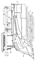
本発明の一実施例をコンバインの図面により説明すると、1はコンバインの機体フレーム、2は機体フレーム1の下方に設けた走行装置、3は機体フレーム1の上方に設けた脱穀装置、4は脱穀装置3の前側に設けた刈取部、5は脱穀装置3の側部に設けたグレンタンク、6はグレンタンク5の前側に設けた操縦部、7は脱穀装置3の後側に設けたカッターである。
前記脱穀装置3は、上部に扱歯10を有する扱胴11を略水平に軸装した脱穀室12を設け、脱穀室12の一側には前記刈取部により刈り取った穀稈を供給搬送する穀稈供給搬送装置13の供給搬送チェン14を設けている。なお、理解を容易にするため、便宜的に方向を示して以下説明するが、これにより構成が限定されるものではない。
扱胴11は脱穀装置3の前板16と脱穀室後板17に軸装し、扱胴11の主として下方側は扱網18により包囲している。扱網18の下方には送風唐箕19の唐箕ケーシング20を設ける。前記脱穀室12の下方には前記送風唐箕19の送風により穀粒と異物とを風選し得る風選室21を形成し、風選室21内には、送風唐箕19の送風方向(前後方向)に往復揺動する揺動選別棚25により構成した揺動選別装置26を設ける。
DESCRIPTION OF THE PREFERRED EMBODIMENTS An embodiment of the present invention will be described with reference to the drawings of a combine. Reference numeral 1 denotes a fuselage frame of the combine, 2 a traveling device provided below the fuselage frame 1, 3 a threshing device provided above the fuselage frame 1, and 4 a threshing The mowing part provided on the front side of the apparatus 3, 5 is a Glen tank provided on the side part of the threshing apparatus 3, 6 is a control part provided on the front side of the grain tank 5, and 7 is a cutter provided on the rear side of the threshing apparatus 3. is there.
The threshing device 3 is provided with a threshing chamber 12 having a handle cylinder 11 having a handle 10 on the upper part thereof, and a threshing chamber 12 which is cut and harvested by the reaping portion on one side of the threshing chamber 12. A supply conveyance chain 14 of the ridge supply conveyance device 13 is provided. For ease of understanding, the following explanation will be given for the sake of convenience, but the configuration is not limited thereby.
The handling cylinder 11 is mounted on the front plate 16 and the threshing chamber rear plate 17 of the threshing device 3, and the lower side of the handling cylinder 11 is surrounded by a handling net 18. A tang casing 20 for the blast tang 19 is provided below the handling net 18. Below the threshing chamber 12, a wind selection chamber 21 that can wind-select grains and foreign matters by blowing air from the blower tang 19 is formed. ) Is provided with a swing sorting device 26 constituted by a swing sorting shelf 25 that swings back and forth.

揺動選別装置26の構成は任意であるが、一例を示すと、前記揺動選別棚25の始端部(前端部)を唐箕ケーシング20の上方に位置させて上下二段に並設した移送棚部27、28に形成する。各移送棚部27、28の上面には突起や凹凸を設けて揺動選別装置26の移送方向下手側に扱網18からの落下物を移送できればよい。
上側移送棚部27の移送方向下手側にはグレンシーブ30を設ける。グレンシーブ30は、扱網18より落下した穀粒と異物とを選別するものであり、所定間隔をおいて揺動方向に複数並設する。グレンシーブ30は、薄い平板形状に形成し、移送方向の下手側(後側)が高くなるように傾斜させて設ける。
下側移送棚部28の始端部は上側移送棚部27よりも前側に位置させ、下側移送棚部28の移送方向下手側には選別網31を設ける。選別網31はグレンシーブ30より落下した穀粒と異物とを選別するものである。
The configuration of the swing sorting device 26 is arbitrary, but as an example, a transfer shelf in which the start end (front end) of the swing sorting shelf 25 is positioned above the Karatsu casing 20 and arranged in parallel in two stages. Formed in portions 27 and 28. It is only necessary that protrusions and irregularities are provided on the upper surfaces of the respective transfer shelves 27 and 28 so that falling objects from the handling net 18 can be transferred to the lower side of the swing sorting device 26 in the transfer direction.
On the lower side of the upper transfer shelf 27 in the transfer direction, a grain sheave 30 is provided. Glen sieves 30 are used to sort out grains and foreign substances that have fallen from the handling net 18, and are arranged in parallel in a swinging direction at a predetermined interval. The grain sheave 30 is formed in a thin flat plate shape, and is inclined so that the lower side (rear side) in the transfer direction is higher.
The starting end portion of the lower transfer shelf portion 28 is positioned in front of the upper transfer shelf portion 27, and a sorting net 31 is provided on the lower side of the lower transfer shelf portion 28 in the transfer direction. The sorting net 31 sorts grains and foreign matters that have fallen from the grain sieve 30.

グレンシーブ30の下方から移送方向の下手側(後側)のストローラック32を設ける。 揺動選別棚25の下方には一番コンベア34を設け、一番コンベア34の後側には二番コンベア35を設ける。
しかして、扱胴11の後方(終端側)には、四番処理装置36を設ける。四番処理装置36は、脱穀室後板17の後方に仕切板37を設け、脱穀室後板17と仕切板37との間に四番処理胴38を軸装して構成する。四番処理装置36は搬送中の搬送穀稈の枝梗粒および搬送穀稈中に刺さっている刺さり粒等を四番処理胴38により落下処理するものである。
実施例の四番処理装置36は、脱穀室12の後部に四番処理胴38を一体状に形成し、四番処理胴38の外周には処理歯39を設けている。処理歯39は、搬送穀稈中に刺さっている刺さり粒を落下させるのものであり、この点、穀稈から穀粒を分離する脱穀作用を奏する扱歯10と区別される。四番処理装置36は扱胴11の終端の扱歯10と処理歯39の間の四番処理胴38の外周を脱穀室後板17により包囲し、脱穀室後板17と仕切板37との間に形成する。
A stroller 32 on the lower side (rear side) in the transfer direction is provided from below the grain sheave 30. A first conveyor 34 is provided below the swing sorting shelf 25, and a second conveyor 35 is provided behind the first conveyor 34.
Therefore, a fourth processing device 36 is provided behind the handling cylinder 11 (on the end side). The fourth processing device 36 is configured by providing a partition plate 37 behind the threshing chamber rear plate 17 and pivoting a fourth processing cylinder 38 between the threshing chamber rear plate 17 and the partition plate 37. The fourth processing device 36 performs drop processing on branch branch grains of the transported cereal being transported and stabbed grains stabbed in the transported cereal by the fourth processing cylinder 38.
In the fourth processing device 36 of the embodiment, a fourth processing cylinder 38 is integrally formed at the rear portion of the threshing chamber 12, and processing teeth 39 are provided on the outer periphery of the fourth processing cylinder 38. The treated tooth 39 is used to drop the stabbed grains that are stuck in the conveying cereal, and is distinguished from the tooth handling 10 that has a threshing action for separating the grains from the cereal. The fourth processing device 36 surrounds the outer periphery of the fourth processing cylinder 38 between the tooth teeth 10 and the processing teeth 39 at the end of the processing cylinder 11 by the threshing chamber rear plate 17, and the threshing chamber rear plate 17 and the partition plate 37. Form between.

前記脱穀室12の後部および四番処理装置36の側方には、排塵処理室40を設ける。排塵処理室40は、扱胴11の軸心と略平行な排塵処理胴41を軸装して構成する。排塵処理胴41の外周には処理歯42を設け、処理歯42の主として下方側は処理網43により包囲する。排塵処理室40は、脱穀室12の後部に設けた排塵連通口44により脱穀室12と連通させている。
前記脱穀室12の側方には、二番コンベア35により回収された二番物を処理する二番処理装置45を設ける。二番処理装置45の始端部上方には二番還元装置46の先端を開口させ、二番還元装置46の基部は二番コンベア35の終端に接続している。二番処理装置45は排塵処理胴40と同心状に二番処理胴47を軸装し、二番処理胴47の外周には二番処理歯48を設け、二番処理胴47の主として下方側は二番処理網49により包囲する。二番処理歯48は、穀稈供給搬送装置13の搬送方向と反対に揺動選別棚25の始端部(前端部)側に二番処理物を移送するように配置する。
A dust disposal chamber 40 is provided at the rear of the threshing chamber 12 and on the side of the fourth processing unit 36. The dust removal processing chamber 40 is configured by mounting a dust removal treatment cylinder 41 substantially parallel to the axis of the handling cylinder 11. Processing teeth 42 are provided on the outer periphery of the dust removal processing cylinder 41, and the lower side of the processing teeth 42 is surrounded by a processing net 43. The dust removal processing chamber 40 is communicated with the threshing chamber 12 by a dust discharge communication port 44 provided at the rear portion of the threshing chamber 12.
On the side of the threshing chamber 12, a second processing device 45 for processing the second item collected by the second conveyor 35 is provided. The tip of the second reduction device 46 is opened above the starting end of the second processing device 45, and the base of the second reduction device 46 is connected to the end of the second conveyor 35. The second processing unit 45 is provided with a second processing cylinder 47 concentrically with the dust processing cylinder 40, and a second processing tooth 48 is provided on the outer periphery of the second processing cylinder 47, mainly below the second processing cylinder 47. The side is surrounded by a second processing network 49. The second processing teeth 48 are arranged so as to transfer the second processed material to the start end portion (front end portion) side of the swing sorting shelf 25 in the opposite direction to the conveying direction of the grain supply / conveying device 13.

二番処理胴47の先端外周には二番処理胴47の軸心と略平行な排出羽根50を設け、排出羽根排出羽根50の略直下に二番処理物排出口51を形成し、二番処理物排出口51は下側移送棚部28の始端部上方に開口させる。
しかして、脱穀装置3内には、四番処理装置36から排出される穀粒と排塵処理室40から排出される穀粒を回収して、揺動選別棚25の始端部に搬送する三番処理装置55を設ける。三番処理装置55は四番処理装置36および排塵処理室40から排出される穀粒を揺動選別棚25の中間部に直接落下させずに回収して、揺動選別棚25の始端部まで搬送するので、選別ロスを低減させて、脱穀能力を向上させる。
即ち、揺動選別棚25の中間部上面では、大量の藁屑が移動中であり、この状態の揺動選別棚25の中間部に四番処理装置36および排塵処理室40から排出された穀粒を落下させても、そのまま揺動選別棚25により機外に排出されて選別ロスとなってしまうが、三番処理装置55により回収して藁屑発生の少ない揺動選別棚25の始端部に戻すので、一番コンベア34により回収する回収効率を向上させる。
A discharge blade 50 substantially parallel to the axial center of the second processing cylinder 47 is provided on the outer periphery of the tip of the second processing cylinder 47, and a second processed material discharge port 51 is formed substantially immediately below the discharge blade discharge blade 50. The processed product discharge port 51 is opened above the start end of the lower transfer shelf 28.
Thus, in the threshing apparatus 3, the grains discharged from the fourth processing apparatus 36 and the grains discharged from the dust removal processing chamber 40 are collected and transferred to the starting end of the swing sorting shelf 25. A number processing device 55 is provided. The third processing unit 55 collects the grains discharged from the fourth processing unit 36 and the dust processing chamber 40 without dropping them directly to the middle part of the swing sorting shelf 25, and starts the end of the swing sorting shelf 25. Therefore, the sorting loss is reduced and the threshing ability is improved.
That is, a large amount of soot is moving on the upper surface of the middle part of the swing sorting shelf 25 and is discharged from the fourth processing device 36 and the dust disposal chamber 40 to the middle part of the swing sorting shelf 25 in this state. Even if the grain is dropped, it is discharged out of the machine as it is by the swinging sorting shelf 25 and becomes a sorting loss. However, the beginning of the swinging sorting shelf 25 that is recovered by the third processing device 55 and generates less debris. Therefore, the recovery efficiency of recovery by the conveyor 34 is improved.

また、三番処理装置55を設けることにより脱穀室12の負荷も軽減させ、特に、早朝や高水分穀稈の脱穀の場合、負荷は大きく、三番処理装置55はこの負荷の軽減に貢献する。
前記三番処理装置55は、扱胴11の軸芯と平行方向の受樋56を設け、受樋56内に三番処理胴57を設けて構成し、受樋56の外周には螺旋状の処理歯58を設け、受樋56内に回収された回収物を揺動選別棚25の始端部に搬送中に三番処理胴57の回転により枝梗粒や搬送穀稈中に刺さっている刺さり粒等の再処理も期待する。
三番処理胴57の先端外周には三番処理胴57の軸心と略平行な排出羽根60を設け、排出羽根60の略直下に三番処理物排出口61を形成し、三番処理物排出口61は下側移送棚部28の始端部上方に開口させる。
Moreover, the load of the threshing chamber 12 is reduced by providing the third processing device 55, and particularly in the case of threshing early morning or high moisture cereal, the load is large, and the third processing device 55 contributes to the reduction of this load. .
The third processing device 55 is configured by providing a receiving rod 56 in a direction parallel to the axis of the handling cylinder 11, and providing a third processing cylinder 57 inside the receiving rod 56. The processing teeth 58 are provided, and the collected material collected in the receiving basket 56 is stabbed into branch branch grains or the transported culm by the rotation of the third processing cylinder 57 while it is transported to the start end of the swing sorting shelf 25. Expect reprocessing of grains.
A discharge blade 60 substantially parallel to the axial center of the third processing cylinder 57 is provided on the outer periphery of the tip of the third processing cylinder 57, and a third processed material discharge port 61 is formed almost directly below the discharge blade 60. The discharge port 61 is opened above the starting end of the lower transfer shelf 28.

しかして、四番処理胴38の下面下方には所定間隔を置いて設け、四番処理物受け板59を所定間隔を置いて設け、四番処理物受け板59の右端部は受樋56に接続する。
即ち、穀稈供給搬送装置13により搬送された搬送穀稈は、脱穀室12で脱穀処理されると、脱穀室12の後方に設けた四番処理装置36で、回転する四番処理胴38の処理歯39により搬送穀稈中に刺さり込んでいる刺さり粒を四番処理物受け板59に落下させ、落下した穀粒は四番処理物受け板59により三番処理装置55の受樋56に誘導されて回収される。
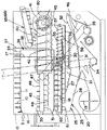
しかして、穀稈供給搬送装置13の供給搬送チェン14の終端には、排藁搬送装置65の排藁搬送チェン66の始端部を臨ませ、排藁搬送装置65の下方には三番処理装置55および三番処理装置55に落下した刺さり粒を誘導する排藁刺さり粒回収板67を設け、四番処理物受け板59の後端と刺さり粒回収板67の前端を接続し、四番処理物受け板59と刺さり粒回収板67とを一体状に設ける。
したがって、四番処理装置36で落下した刺さり粒および排藁搬送装置65により搬送中の排藁に付着している枝梗粒や刺さり粒は、四番処理物受け板59と刺さり粒回収板67上に落下し、四番処理物受け板59と刺さり粒回収板67上に落下した穀粒は三番処理装置55の受樋56に誘導されて回収される。
Accordingly, a lower surface of the fourth processing cylinder 38 is provided at a predetermined interval, a fourth processed material receiving plate 59 is provided at a predetermined interval, and a right end portion of the fourth processed material receiving plate 59 is attached to the receiving rod 56. Connecting.
That is, when the cereals conveyed by the cereal supply and transfer device 13 are threshed in the threshing chamber 12, the fourth processing device 36 provided at the rear of the threshing chamber 12 causes the rotating fourth processing cylinder 38 to rotate. The stabbed grains that have been stabbed into the transported cereal by the processing teeth 39 are dropped onto the fourth processed product receiving plate 59, and the dropped grains are received by the fourth processed product receiving plate 59 into the receiving cage 56 of the third processing device 55. Guided and collected.
Thus, the starting end of the waste transporting chain 66 of the waste transporting device 65 faces the terminal end of the supply transport chain 14 of the cereal supply transporting device 13, and the third processing device is located below the waste transporting device 65. 55 and the No. 3 processing device 55 are provided with a waste bite recovery plate 67 for guiding the dropped bites, connecting the rear end of the fourth processed material receiving plate 59 and the front end of the bite recovery plate 67 to the fourth processing The object receiving plate 59 and the stabbed grain collecting plate 67 are provided integrally.
Therefore, the stabbing grains dropped by the fourth processing device 36 and the branch rachis and stabbing grains adhering to the waste being transported by the waste transporting device 65 are treated by the fourth processed material receiving plate 59 and the stinging grain recovery plate 67. The grains that fall on the top and fall on the fourth processed material receiving plate 59 and the stabbed grain collecting plate 67 are guided and collected by the receiving bowl 56 of the third processing device 55.

前記刺さり粒回収板67の左側側縁は、平面視、一部切り欠いて排藁搬送装置65の排藁搬送チェン66と略平行となるように配置する(図3)。
即ち、搬送中の排藁の穂先の移動軌跡に沿って、穂先の移動軌跡の下方に刺さり粒回収板67を位置させて、刺さり粒等の回収効率を向上させると共に、排藁の株元側の移動軌跡下方は開放して、排藁搬送チェン66で搬送中の排藁から落下する藁屑は刺さり粒回収板67で回収しないようにしている。
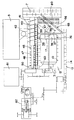
前記三番処理装置55は、背面視、扱胴11と排塵処理胴41との間に設ける(図5)。
したがって、三番処理装置55と揺動選別棚25との間に隙間を十分に確保しつつ、脱穀装置3の高さを低く抑えられる。
The left side edge of the stabbed grain collection plate 67 is partially cut away in a plan view and arranged so as to be substantially parallel to the waste transport chain 66 of the waste transport device 65 (FIG. 3).
That is, along the movement trajectory of the tip of the excretion being transported, the stabbed grain collection plate 67 is positioned below the trajectory of the tip of the tip to improve the recovery efficiency of the stabbed grain etc. The lower part of the movement trajectory is opened so that the waste falling from the waste being transported by the waste transporting chain 66 is not recovered by the stabbed grain recovery plate 67.
The third processing device 55 is provided between the handling cylinder 11 and the dust removal processing cylinder 41 when viewed from the back (FIG. 5).
Therefore, the height of the threshing device 3 can be kept low while ensuring a sufficient gap between the third processing device 55 and the swing sorting shelf 25.

また、前記三番処理装置55は、背面視、四番処理胴38と排塵処理胴41との間に設ける(図5)。
したがって、三番処理装置55と揺動選別棚25との間に隙間を十分に確保しつつ、脱穀装置3の高さを低く抑えられる。
前記三番処理装置55は、背面視、二番処理胴47と扱胴11との間に設ける(図5)。
即ち、三番処理装置55は、二番処理装置45の終端下方まで延長配置して、二番処理装置45の二番処理物排出口51より二番処理物を揺動選別棚25の始端部に排出羽根60により拡散排出させる。
したがって、三番処理装置55と揺動選別棚25との間に隙間を十分に確保しつつ、脱穀装置3の高さを低く抑えられる。
この場合、三番処理装置55の処理歯58は、扱胴11と排塵処理胴41の径より小径に形成する(図5)。
したがって、三番処理装置55と揺動選別棚25との間に隙間を十分に確保しつつ、脱穀装置3の高さを低く抑えられる。
Further, the third processing device 55 is provided between the fourth processing cylinder 38 and the dust removal processing cylinder 41 when viewed from the back (FIG. 5).
Therefore, the height of the threshing device 3 can be kept low while ensuring a sufficient gap between the third processing device 55 and the swing sorting shelf 25.
The third processing device 55 is provided between the second processing cylinder 47 and the handling cylinder 11 when viewed from the back (FIG. 5).
That is, the third processing device 55 is arranged to extend below the end of the second processing device 45, and the second processed material is fed from the second processed material discharge port 51 of the second processing device 45 to the start end of the swing sorting shelf 25. Are discharged by the discharge vanes 60.
Therefore, the height of the threshing device 3 can be kept low while ensuring a sufficient gap between the third processing device 55 and the swing sorting shelf 25.
In this case, the processing teeth 58 of the third processing device 55 are formed to have a smaller diameter than the diameters of the handling cylinder 11 and the dust removal processing cylinder 41 (FIG. 5).
Therefore, the height of the threshing device 3 can be kept low while ensuring a sufficient gap between the third processing device 55 and the swing sorting shelf 25.

しかして、排塵処理胴41は、背面視、その略右側半分を、脱穀装置3の側板70より外側に突出させ、排塵処理胴41の略左側半分は揺動選別棚25の上方に臨むように配置し、この排塵処理胴41と扱胴11との間の下方に三番処理装置55を設けるように構成する(図5)。
したがって、脱穀装置3の左右幅を狭くでき、コンパクトな脱穀機となる。
前記三番処理装置55は、背面視、扱胴11と排塵処理胴41との間の下方に設ける(図5)。
したがって、三番処理装置55と揺動選別棚25との間に隙間を十分に確保しつつ、脱穀装置3の高さを低く抑えられる。
Accordingly, the dust removal processing cylinder 41 has a substantially right half of the dust removal processing cylinder 41 protruding outward from the side plate 70 of the threshing device 3, and a substantially left half of the dust collection processing cylinder 41 faces above the swing sorting shelf 25. The third processing device 55 is provided below the dust processing cylinder 41 and the handling cylinder 11 (FIG. 5).
Therefore, the left and right width of the threshing device 3 can be narrowed, and a compact threshing machine is obtained.
The third processing device 55 is provided in the rear view and between the handling cylinder 11 and the dust removal processing cylinder 41 (FIG. 5).
Therefore, the height of the threshing device 3 can be kept low while ensuring a sufficient gap between the third processing device 55 and the swing sorting shelf 25.

しかして、三番処理装置55の処理胴57は、扱胴11と二番処理胴47の径より小径に形成する(図5)。
したがって、三番処理装置55と揺動選別棚25との間に隙間を十分に確保しつつ、脱穀装置3の高さを低く抑えられる。
しかして、二番処理装置45の二番処理胴47は、背面視、その略右側半分を、脱穀装置3の側板70より外側に突出させ(図5)、二番処理胴47の略左側半分は揺動選別棚25の上方に臨むように配置し、この二番処理胴47と扱胴11との間の下方に三番処理装置55を設けるように構成する。
したがって、脱穀装置3の左右幅を狭くでき、コンパクトな脱穀機となる。
Therefore, the processing cylinder 57 of the third processing apparatus 55 is formed to have a smaller diameter than the diameters of the processing cylinder 11 and the second processing cylinder 47 (FIG. 5).
Therefore, the height of the threshing device 3 can be kept low while ensuring a sufficient gap between the third processing device 55 and the swing sorting shelf 25.
Thus, the second processing cylinder 47 of the second processing apparatus 45 has a substantially right half projected from the side plate 70 of the threshing apparatus 3 when viewed from the rear (FIG. 5). Are arranged so as to face above the swing sorting shelf 25, and a third processing device 55 is provided below the second processing cylinder 47 and the handling cylinder 11.
Therefore, the left and right width of the threshing device 3 can be narrowed, and a compact threshing machine is obtained.

また、二番処理装置45および四番処理胴38から排出される穀粒と、排塵処理胴41から落下排出される穀粒と、排藁搬送装置65の搬送排藁から落下する穀粒を、全て三番処理装置55により回収し、三番処理装置55により揺動選別棚25の始端部に搬送し、揺動選別棚25に拡散排出するので、選別ロスを低減でき、脱穀能力を向上できる。
しかして、二番処理装置45の二番処理胴47は、背面視、その略右側半分を、脱穀装置3の側板70より外側に突出させ、二番処理胴47の略左側半分は三番処理装置55の受樋56の上方に臨むように配置し、二番処理装置45の二番処理網49から漏れた穀粒を三番処理装置55に回収すると共に、三番処理装置55はこの二番処理胴47と扱胴11との間の下方に設け、扱網18から漏れた穀粒を三番処理装置55に回収するように構成する(図5)。
Moreover, the grain discharged | emitted from the 2nd processing apparatus 45 and the 4th processing cylinder 38, the grain dropped and discharged from the dust removal processing cylinder 41, and the grain falling from the conveyance waste of the waste conveying apparatus 65 , All collected by the No. 3 processing device 55, transported to the starting end of the swing sorting shelf 25 by the No. 3 processing device 55, and diffused and discharged to the swing sorting shelf 25, so that the sorting loss can be reduced and the threshing ability is improved. it can.
Thus, the second processing cylinder 47 of the second processing apparatus 45 has a substantially right half projected from the rear plate 70 outside the side plate 70 of the threshing apparatus 3, and the substantially left half of the second processing cylinder 47 is third processed. It arrange | positions so that it may face over the receiving trough 56 of the apparatus 55, and while recovering the grain which leaked from the 2nd processing net | network 49 of the 2nd processing apparatus 45 to the 3rd processing apparatus 55, the 3rd processing apparatus 55 is this 2nd. It is provided below between the number processing cylinder 47 and the handling cylinder 11, and is configured such that the grain leaked from the handling net 18 is collected in the third processing apparatus 55 (FIG. 5).

したがって、脱穀装置3の左右幅を狭くでき、コンパクトな脱穀機となるばかりでなく、また、二番処理装置45および四番処理胴38から排出される穀粒と、排塵処理胴41から落下排出される穀粒と、排藁搬送装置65の搬送排藁から落下する穀粒、および、脱穀室12の扱網18から漏下した穀粒の一部を、三番処理装置55により回収し、三番処理装置55により揺動選別棚25の始端部に搬送し、揺動選別棚25に拡散排出するので、選別ロスを低減でき、脱穀能力を向上できる。
図中、80は吸引排塵ファン、81はエンジン、82はミッションである。
Accordingly, the left and right widths of the threshing device 3 can be reduced, and not only a compact threshing machine can be obtained, but also the grains discharged from the second processing device 45 and the fourth processing drum 38 and the dust removal processing drum 41 fall. The third processing device 55 collects the discharged grains, the grains falling from the transport waste of the waste transporting device 65, and a part of the grain leaked from the handling net 18 of the threshing chamber 12. Since the third processing device 55 transports it to the starting end of the swing sorting shelf 25 and diffuses and discharges it to the swing sorting shelf 25, the sorting loss can be reduced and the threshing ability can be improved.
In the figure, 80 is a suction dust exhaust fan, 81 is an engine, and 82 is a mission.

(実施例の作用)
走行装置2により走行し、刈取部4で刈り取った穀稈は穀稈供給搬送装置13の供給搬送チェン14により搬送されて、脱穀室12に供給され、脱穀室12の扱胴11で脱穀される。脱穀された脱穀物は、扱網18より揺動選別棚25に落下し、揺動選別棚25の揺動と送風唐箕19からの送風により選別され、穀粒は揺動選別棚25の選別網選別網31から一番コンベア34に回収され、一番コンベア34により回収された穀粒はグレンタンク5に貯留される。
(Operation of Example)
The cereals that have traveled by the traveling device 2 and that have been harvested by the reaping unit 4 are transported by the supply transport chain 14 of the cereal supply and transport device 13, supplied to the threshing chamber 12, and threshed by the handling cylinder 11 of the threshing chamber 12. . The threshed threshing drops from the handling net 18 to the swing sorting shelf 25 and is sorted by swinging the swing sorting shelf 25 and blowing from the blower 19, and the grains are sorted by the swing sorting shelf 25. The grain recovered from the sorting net 31 to the first conveyor 34 and stored by the first conveyor 34 is stored in the Glen tank 5.

また、二番コンベア35に回収された二番物は二番還元装置46により二番処理装置45に還元され、二番処理装置45の二番処理胴47により再処理されて揺動選別棚25の始端部に拡散排出される。
また、穀稈供給搬送装置13により搬送された搬送穀稈は、脱穀室12で脱穀処理されると、脱穀室12の後方に設けた四番処理装置36で、回転する四番処理胴38の処理歯39により搬送穀稈中に刺さり込んでいる刺さり粒が落下処理され、種々の経路を経て揺動選別棚25に回収される。
Further, the second item collected on the second conveyor 35 is returned to the second processing unit 45 by the second reduction unit 46 and reprocessed by the second processing cylinder 47 of the second processing unit 45, and the swing sorting shelf 25. It is diffused and discharged at the start end.
In addition, when the cereals conveyed by the cereal supply and transfer device 13 are threshed in the threshing chamber 12, the fourth processing device 36 provided at the rear of the threshing chamber 12 is used to rotate the fourth processing cylinder 38. The treated teeth 39 drop the stabbed grains that have been stabbed into the transported cereal and collect them in the swing sorting shelf 25 through various paths.

また、脱穀室12で脱穀された脱穀物のうち、扱網18より落下しない脱穀物の一部は排塵連通口44から排塵処理装置40に入って処理される。
また、揺動選別棚25上の処理物は風選室21で風選され、揺動選別棚25より落下しない処理物のうち藁屑・塵埃は吸引排塵ファン80により機外に吸引排出される。
この場合、一番コンベア34に回収される穀粒を「一番物」、二番コンベア35に回収される穀粒と他の被処理物を「二番物」、揺動選別棚25上の被処理物と共に揺動選別棚25の後部から機外に排出される被処理物(含む穀粒)を「三番物」、排藁搬送装置65により搬送中の排藁に混入して機外に排出される穀粒、青米、その他のものを「四番物」と当業者はそれぞれ呼んでおり、本願では、三番処理装置55を設けているので、従来であれば、排塵処理装置40や二番処理装置45から揺動選別棚25に直接落下して排出されてしまう穀粒を三番処理装置55により回収して、三番ロスを低減させる。
Further, among the cereals threshed in the threshing chamber 12, a part of the cereal that does not fall from the handling net 18 enters the dust removal processing device 40 through the dust removal communication port 44 and is processed.
Further, the processed material on the swing sorting shelf 25 is wind-selected in the wind sorting chamber 21, and among the processed products that do not fall from the swing sorting shelf 25, the dust and dust are sucked and discharged outside the apparatus by the suction dust exhaust fan 80. The
In this case, the grain collected on the first conveyor 34 is the “first thing”, the grain collected on the second conveyor 35 and the other object to be treated are “second thing”, and on the swing sorting shelf 25. The material to be processed (including grains) discharged from the rear part of the swing sorting shelf 25 together with the material to be processed is mixed into the waste that is being transported by the waste transporting device 65 by the waste transporting device 65. Grains, blue rice and other items discharged to the sea are called “fourth thing” by those skilled in the art, and in the present application, the third treatment device 55 is provided. Grains that fall directly from the apparatus 40 or the second processing apparatus 45 to the swing sorting shelf 25 and are discharged are collected by the third processing apparatus 55 to reduce the third loss.

また、前記した各実施例は、理解を容易にするために、個別または混在させて図示、あるいは説明しているが、これらは夫々種々組合せ可能であり、これらの表現によって、構成・作用等が限定されるものではなく、また、相乗効果を奏する場合も勿論存在する。   In addition, each of the above-described embodiments is illustrated or described individually or mixedly for easy understanding, but these can be combined in various ways, and the expression, configuration, action, etc. It is not limited, and there are of course cases where a synergistic effect is obtained.

コンバインの側面図。The side view of a combine. 脱穀装置の側面図。The side view of a threshing apparatus. 同平面図。FIG. 同平面図(二番処理胴および排塵処理胴省略)。The same plan view (No. 2 processing cylinder and dust removal processing cylinder omitted). 同背面図。The rear view. 同一部斜視図。The same part perspective view.

1…機体フレーム、2…走行装置、3…脱穀装置、4…刈取部、5…グレンタンク、6…操縦部、7…カッター、11…扱胴、12…脱穀室、13…穀稈供給搬送装置、14…供給搬送チェン、16…前板、17…脱穀室後板、18…扱網、19…送風唐箕、20…唐箕ケーシング、21…風選室、25…揺動選別棚、26…揺動選別装置、27…移送棚部、28…移送棚部、30…グレンシーブ、31…選別網、32…ストローラック、34…一番コンベア、35…二番コンベア、36…四番処理装置、37…仕切板、38…四番処理胴、39…処理歯、40…排塵処理装置、41…排塵処理胴、42…処理歯、43…処理網、44…排塵連通口、46…二番還元装置、47…二番処理胴、48…二番処理歯、49…二番処理網、50…排出羽根、51…二番処理物排出口、55…三番処理装置、56…受樋、57…三番処理胴、58…処理歯、59…四番処理物受け板、60…排出羽根、61…三番処理物排出口、63…網体、65…排藁搬送装置、66…チェン、67…刺さり粒回収板,70…側板。 DESCRIPTION OF SYMBOLS 1 ... Airframe frame, 2 ... Traveling apparatus, 3 ... Threshing apparatus, 4 ... Cutting part, 5 ... Glen tank, 6 ... Steering part, 7 ... Cutter, 11 ... Handling cylinder, 12 ... Threshing room, 13 ... Grain supply conveyance Equipment: 14 ... Supply conveyance chain, 16 ... Front plate, 17 ... Threshing chamber rear plate, 18 ... Handling net, 19 ... Air blow casing, 20 ... Karatsu casing, 21 ... Wind selection chamber, 25 ... Swing sorting shelf, 26 ... Oscillating sorting device, 27 ... transfer shelf, 28 ... transfer shelf, 30 ... glen sieve, 31 ... sorting screen, 32 ... straw rack, 34 ... first conveyor, 35 ... second conveyor, 36 ... fourth processor, 37 ... partition plate, 38 ... fourth treatment cylinder, 39 ... treatment tooth, 40 ... dust removal processing device, 41 ... dust removal treatment cylinder, 42 ... treatment tooth, 43 ... treatment net, 44 ... dust removal communication port, 46 ... No. 2 reduction device, 47 ... No. 2 processing cylinder, 48 ... No. 2 processing teeth, 49 ... No. 2 processing net, 50 ... Exhaust Blades 51, No. 2 processed material discharge port, 55, No. 3 processing device, 56, receiving bowl, 57, No. 3 processing cylinder, 58, processing teeth, 59, fourth processed article receiving plate, 60, discharging vane, 61 3rd processed material discharge port, 63 ... Net body, 65 ... Discharge conveying device, 66 ... Chain, 67 ... Stinging grain recovery plate, 70 ... Side plate.

Claims (4)

上部に扱胴(11)を軸装して、穀稈供給搬送装置(13)により搬送される穀稈を脱穀する脱穀室(12)を設け、脱穀室(12)の扱網(18)の下方に、送風唐箕からの送風と揺動により穀粒とその他の処理物を風選する揺動選別棚(25)により構成した揺動選別装置(26)を設け、前記脱穀室(12)の後方には処理歯(39)を設けた四番処理胴(38)を軸装して搬送穀稈中に刺さり込んでいる刺さり粒を落下処理させる四番処理装置(36)を設け、脱穀室(12)の後側側部には、扱胴(11)の軸心と略平行で外周に処理歯(42)を有する排塵処理胴(41)を軸装し、脱穀室(12)と排塵連通口(44)により連通する排塵処理室(40)を設け、背面視、前記四番処理胴(38)と排塵処理胴(41)との間に、四番処理胴(38)と排塵処理胴(41)から落下する穀粒を回収して、前記揺動選別棚(25)の始端部に搬送する三番処理装置(55)を設けた脱穀装置。 A threshing chamber (12) for threshing the culm that is conveyed by the cereal supply and transfer device (13) is provided on the upper portion of the handling cylinder (11), and the threshing chamber (12) of the threshing chamber (12) is provided. A swing sorting device (26) constituted by a swing sorting shelf (25) for wind-selecting the grains and other processed materials by blowing and swinging from the blower tang is provided below the threshing chamber (12). In the rear, there is provided a fourth processing device (36) for axially mounting a fourth processing cylinder (38) provided with processing teeth (39) to drop-process the stabbed grains that have been inserted into the conveying cereal, and a threshing chamber (12) On the rear side portion, a dust removal processing cylinder (41) having a processing tooth (42) on the outer periphery and substantially parallel to the axial center of the handling cylinder (11) is mounted, dust-exhaust process chamber communicating with Haichirirendoriguchi (44) to (40) is provided, the back surface view, between the fourth wheel processing cylinder (38) and the dust-exhaust processing cylinder (41) The third processing device (55) is provided for collecting the grains falling from the fourth processing cylinder (38) and the dust exhausting processing cylinder (41) and transporting them to the starting end of the swing sorting shelf (25). Threshing device. 請求項1において、前記三番処理装置(55)は、扱胴(11)の軸芯と平行方向の受樋(56)を設け、受樋(56)内に外周に螺旋状の処理歯(58)を有する三番処理胴(57)を設けて構成し、前記三番処理装置(55)の受樋(56)は前記四番処理胴(38)の下方に設けた四番処理物受け板(59)と接続した脱穀装置。 In Claim 1, the said 3rd processing apparatus (55) provides the receiving rod (56) of a parallel direction with the axial center of a handling cylinder (11), and has a helical processing tooth on the outer periphery in a receiving rod (56) ( 58), a third processing cylinder (57) is provided, and a receiving rod (56) of the third processing apparatus (55) is a fourth processing object receiver provided below the fourth processing cylinder (38). Threshing device connected to the plate (59). 請求項2において、前記穀稈供給搬送装置(13)の供給搬送チェン(14)の終端には、排藁搬送装置(65)の排藁搬送チェン(66)の始端部を臨ませ、排藁搬送装置(65)の下方には落下した刺さり粒を誘導する刺さり粒回収板(67)を設け、該刺さり粒回収板(67)の前端は四番処理物受け板(59)の後端を接続し、該刺さり粒回収板(67)は前記四番処理物受け板(59)と一体状に設けた脱穀装置。 In Claim 2, the starting end part of the waste conveying chain (66) of the waste conveying device (65) is faced to the terminal end of the supply conveying chain (14) of the grain supply and conveying device (13). A stabbed grain collection plate (67) for guiding the fallen stabbed grains is provided below the transfer device (65), and the front end of the stabbed grain collection plate (67) is the rear end of the fourth processed material receiving plate (59). A threshing device that is connected and the stabbed grain collecting plate (67) is provided integrally with the fourth processed material receiving plate (59). 請求項3において、前記刺さり粒回収板(67)の穀稈供給搬送装置(13)側の側縁は、平面視、一部切り欠いて排藁搬送装置(65)の排藁搬送チェン(66)と略平行となるように配置した脱穀装置。 In Claim 3, the side edge by the side of the grain supply conveyance apparatus (13) of the said stinging grain collection | recovery board (67) is notched partially, planarly, the waste conveyance chain (66) of a rejection conveyance apparatus (65) ) And a threshing device arranged so as to be substantially parallel to each other.
JP2006214356A 2006-08-07 2006-08-07 Threshing device Expired - Fee Related JP4623313B2 (en)

Priority Applications (1)

Application Number Priority Date Filing Date Title
JP2006214356A JP4623313B2 (en) 2006-08-07 2006-08-07 Threshing device

Applications Claiming Priority (1)

Application Number Priority Date Filing Date Title
JP2006214356A JP4623313B2 (en) 2006-08-07 2006-08-07 Threshing device

Publications (3)

Publication Number Publication Date
JP2008035782A JP2008035782A (en) 2008-02-21
JP2008035782A5 JP2008035782A5 (en) 2009-08-13
JP4623313B2 true JP4623313B2 (en) 2011-02-02

Family

ID=39171545

Family Applications (1)

Application Number Title Priority Date Filing Date
JP2006214356A Expired - Fee Related JP4623313B2 (en) 2006-08-07 2006-08-07 Threshing device

Country Status (1)

Country Link
JP (1) JP4623313B2 (en)

Families Citing this family (1)

* Cited by examiner, † Cited by third party
Publication number Priority date Publication date Assignee Title
CN109769482B (en) * 2019-04-01 2024-04-26 河南科技大学 Device for pod removal and impurity removal of oil peonies

Citations (5)

* Cited by examiner, † Cited by third party
Publication number Priority date Publication date Assignee Title
JPS62125443U (en) * 1986-01-31 1987-08-10
JPH09289828A (en) * 1996-04-25 1997-11-11 Yanmar Agricult Equip Co Ltd Combine harvester
JPH11318179A (en) * 1998-05-20 1999-11-24 Yanmar Agricult Equip Co Ltd Threshing equipment of combine harvester
JP2006014622A (en) * 2004-06-30 2006-01-19 Iseki & Co Ltd Threshing apparatus
JP2006166809A (en) * 2004-12-16 2006-06-29 Iseki & Co Ltd Threshing apparatus

Patent Citations (5)

* Cited by examiner, † Cited by third party
Publication number Priority date Publication date Assignee Title
JPS62125443U (en) * 1986-01-31 1987-08-10
JPH09289828A (en) * 1996-04-25 1997-11-11 Yanmar Agricult Equip Co Ltd Combine harvester
JPH11318179A (en) * 1998-05-20 1999-11-24 Yanmar Agricult Equip Co Ltd Threshing equipment of combine harvester
JP2006014622A (en) * 2004-06-30 2006-01-19 Iseki & Co Ltd Threshing apparatus
JP2006166809A (en) * 2004-12-16 2006-06-29 Iseki & Co Ltd Threshing apparatus

Also Published As

Publication number Publication date
JP2008035782A (en) 2008-02-21

Similar Documents

Publication Publication Date Title
JP4623313B2 (en) Threshing device
JPH06296424A (en) Threshing device
JP2005013107A (en) Second crop-returning structure for threshing apparatus
JP2008035782A5 (en)
JP2009142234A (en) Combine harvester
JP4730561B2 (en) Threshing device
JP2008022748A (en) Threshing apparatus
JP2008022748A5 (en)
JP4096500B2 (en) Threshing device
JP4600604B2 (en) Threshing device
JP3677919B2 (en) Threshing device
JP2008048696A (en) Thresher
JPH0884523A (en) Thresher
JP3670118B2 (en) Combine swinging sorter
JP5218732B2 (en) Threshing device
JP4766261B2 (en) Threshing device
JP2009125060A (en) Combine harvester
JPH0535U (en) Threshing equipment
JP3684625B2 (en) Threshing device
JP2005328762A (en) Threshing apparatus
JP3997307B2 (en) Threshing device
JP2010246411A (en) Combine harvester
JP2009247332A (en) Waste straw conveying apparatus and combine harvester equipped with the same
JP2002305949A (en) Thresher
JP2007159487A (en) Thresher

Legal Events

Date Code Title Description
A521 Written amendment

Free format text: JAPANESE INTERMEDIATE CODE: A523

Effective date: 20090630

A621 Written request for application examination

Free format text: JAPANESE INTERMEDIATE CODE: A621

Effective date: 20090730

A977 Report on retrieval

Free format text: JAPANESE INTERMEDIATE CODE: A971007

Effective date: 20100928

TRDD Decision of grant or rejection written
A01 Written decision to grant a patent or to grant a registration (utility model)

Free format text: JAPANESE INTERMEDIATE CODE: A01

Effective date: 20101006

A01 Written decision to grant a patent or to grant a registration (utility model)

Free format text: JAPANESE INTERMEDIATE CODE: A01

A61 First payment of annual fees (during grant procedure)

Free format text: JAPANESE INTERMEDIATE CODE: A61

Effective date: 20101019

R150 Certificate of patent or registration of utility model

Ref document number: 4623313

Country of ref document: JP

Free format text: JAPANESE INTERMEDIATE CODE: R150

Free format text: JAPANESE INTERMEDIATE CODE: R150

FPAY Renewal fee payment (event date is renewal date of database)

Free format text: PAYMENT UNTIL: 20131112

Year of fee payment: 3

LAPS Cancellation because of no payment of annual fees