JP4622291B2 - Read-only optical recording medium with unique identification information - Google Patents
Read-only optical recording medium with unique identification information Download PDFInfo
- Publication number
- JP4622291B2 JP4622291B2 JP2004125892A JP2004125892A JP4622291B2 JP 4622291 B2 JP4622291 B2 JP 4622291B2 JP 2004125892 A JP2004125892 A JP 2004125892A JP 2004125892 A JP2004125892 A JP 2004125892A JP 4622291 B2 JP4622291 B2 JP 4622291B2
- Authority
- JP
- Japan
- Prior art keywords
- pit
- pattern
- bit string
- land
- additional
- Prior art date
- Legal status (The legal status is an assumption and is not a legal conclusion. Google has not performed a legal analysis and makes no representation as to the accuracy of the status listed.)
- Expired - Fee Related
Links
Images


Classifications
-
- G—PHYSICS
- G11—INFORMATION STORAGE
- G11B—INFORMATION STORAGE BASED ON RELATIVE MOVEMENT BETWEEN RECORD CARRIER AND TRANSDUCER
- G11B7/00—Recording or reproducing by optical means, e.g. recording using a thermal beam of optical radiation by modifying optical properties or the physical structure, reproducing using an optical beam at lower power by sensing optical properties; Record carriers therefor
- G11B7/007—Arrangement of the information on the record carrier, e.g. form of tracks, actual track shape, e.g. wobbled, or cross-section, e.g. v-shaped; Sequential information structures, e.g. sectoring or header formats within a track
- G11B7/00736—Auxiliary data, e.g. lead-in, lead-out, Power Calibration Area [PCA], Burst Cutting Area [BCA], control information
-
- G—PHYSICS
- G11—INFORMATION STORAGE
- G11B—INFORMATION STORAGE BASED ON RELATIVE MOVEMENT BETWEEN RECORD CARRIER AND TRANSDUCER
- G11B20/00—Signal processing not specific to the method of recording or reproducing; Circuits therefor
- G11B20/10—Digital recording or reproducing
- G11B20/10009—Improvement or modification of read or write signals
-
- G—PHYSICS
- G11—INFORMATION STORAGE
- G11B—INFORMATION STORAGE BASED ON RELATIVE MOVEMENT BETWEEN RECORD CARRIER AND TRANSDUCER
- G11B27/00—Editing; Indexing; Addressing; Timing or synchronising; Monitoring; Measuring tape travel
- G11B27/10—Indexing; Addressing; Timing or synchronising; Measuring tape travel
- G11B27/19—Indexing; Addressing; Timing or synchronising; Measuring tape travel by using information detectable on the record carrier
- G11B27/28—Indexing; Addressing; Timing or synchronising; Measuring tape travel by using information detectable on the record carrier by using information signals recorded by the same method as the main recording
- G11B27/32—Indexing; Addressing; Timing or synchronising; Measuring tape travel by using information detectable on the record carrier by using information signals recorded by the same method as the main recording on separate auxiliary tracks of the same or an auxiliary record carrier
- G11B27/322—Indexing; Addressing; Timing or synchronising; Measuring tape travel by using information detectable on the record carrier by using information signals recorded by the same method as the main recording on separate auxiliary tracks of the same or an auxiliary record carrier used signal is digitally coded
-
- G—PHYSICS
- G11—INFORMATION STORAGE
- G11B—INFORMATION STORAGE BASED ON RELATIVE MOVEMENT BETWEEN RECORD CARRIER AND TRANSDUCER
- G11B7/00—Recording or reproducing by optical means, e.g. recording using a thermal beam of optical radiation by modifying optical properties or the physical structure, reproducing using an optical beam at lower power by sensing optical properties; Record carriers therefor
- G11B7/24—Record carriers characterised by shape, structure or physical properties, or by the selection of the material
- G11B7/26—Apparatus or processes specially adapted for the manufacture of record carriers
- G11B7/268—Post-production operations, e.g. initialising phase-change recording layers, checking for defects
-
- H—ELECTRICITY
- H04—ELECTRIC COMMUNICATION TECHNIQUE
- H04N—PICTORIAL COMMUNICATION, e.g. TELEVISION
- H04N5/00—Details of television systems
- H04N5/76—Television signal recording
- H04N5/84—Television signal recording using optical recording
- H04N5/85—Television signal recording using optical recording on discs or drums
Description
本発明は、固有の識別情報が書き込み可能な再生専用の光記録媒体並びに再生専用の光記録媒体に対して例えば媒体固有の識別情報を書き込むための管理方法、特に、変調方式として1−7パリティ保存変調が適用されている再生専用の光記録媒体に識別情報を記録する方法に関する。さらに、この光記録媒体及び管理方法に関連した光記録媒体製造装置及び方法、識別情報記録装置及び方法、並びに、光記録媒体再生装置及び方法に関する。 The present invention relates to a reproduction-only optical recording medium in which unique identification information can be written and a management method for writing identification information unique to a reproduction-only optical recording medium, particularly 1-7 parity as a modulation method. The present invention relates to a method for recording identification information on a reproduction-only optical recording medium to which storage modulation is applied. Furthermore, the present invention relates to an optical recording medium manufacturing apparatus and method, an identification information recording apparatus and method, and an optical recording medium reproducing apparatus and method related to this optical recording medium and management method.
音楽や映像などの著作物情報をデジタル化して記録することができる情報記録媒体として、CDやDVDなどの再生専用の光記録媒体が広く知られている。音楽、映像などの著作物情報を記録する再生専用録媒体では、著作物の内容に変質のないことが保証されている必要がある。これは、通常、まず、一枚のマスタを作成し、一枚のマスタから次々と再生専用媒体を複製していくことで保証される。 As information recording media capable of digitizing and recording copyrighted work information such as music and video, read-only optical recording media such as CDs and DVDs are widely known. A reproduction-only recording medium for recording copyrighted work information such as music and video needs to ensure that the content of the copyrighted work is not altered. This is usually assured by first creating one master and copying the read-only media from one master to another.
特に、CDやDVDのような、基板の凹凸情報を著作物の情報に対応させて記録された円盤状の再生専用光記録媒体の場合、一枚のマスタから、同じ情報が記録されている再生専用媒体を一度に大量に複製することが可能である。したがって、円盤状の再生専用光記録媒体は、書き換え可能な記録媒体を代用して再生専用媒体とするような他の記録媒体、例えばカセットテープやVHSテープと比較して、複製時のマスタの劣化も少なく、また、複製が格段に容易であり、複製にかかる時間や、コストの観点からも大変有利なものとなっている。 In particular, in the case of a disc-shaped read-only optical recording medium such as a CD or a DVD in which the unevenness information of the substrate is recorded corresponding to the information of the copyrighted work, the same information is recorded from one master. It is possible to duplicate a large amount of dedicated media at once. Therefore, the disc-shaped read-only optical recording medium is deteriorated in the master at the time of duplication as compared with other recording media such as cassette tapes and VHS tapes in which a rewritable recording medium is used instead. In addition, the copying is much easier, and it is very advantageous from the viewpoint of the time and cost for copying.
一方、媒体を管理するという観点から見た場合、このように全ての媒体に同じ情報しか記録できないということは、媒体毎の区別ができなくなるため、必ずしも望ましいものではない。媒体の管理とは、もともとは品質管理などの媒体を製作する側において要求されることが多かったが、近年、上記のCDやDVDに対する1.海賊版、2.不正コピーなどが大きな問題となっており、媒体の海賊版や不正コピーに対する管理、さらには、その内容である著作物に対する著作権の管理という側面からも重要性が増している。 On the other hand, from the viewpoint of managing the medium, the fact that only the same information can be recorded on all the media in this way is not always desirable because it becomes impossible to distinguish each medium. Originally, media management is often required on the side of media production such as quality control. Recently, however, 1. Pirated version, 2. Unauthorized copying has become a major problem, and it is becoming increasingly important from the viewpoint of management of pirated and unauthorized copies of media, as well as copyright management of the copyrighted work.
このような海賊版や不正コピーの管理をする上で問題になるのは、上述のような再生専用記録媒体の特性ゆえに、不正な手段で作成した媒体と正規の媒体とを区別することができない点である。 The problem in managing such pirated copies and unauthorized copies is that it is not possible to distinguish between media created by unauthorized means and legitimate media due to the characteristics of the read-only recording medium as described above. It is.
このような問題を解決するための方法として、再生専用媒体に対して媒体毎の固有情報を記録して管理を行う方法がある。媒体毎に異なる固有情報を記録すると、海賊版や不正コピーをした媒体は固有情報が未記録となったり不正となったりするので、海賊版や不正コピー等の対策として非常に有効となる可能性を秘めている。 As a method for solving such a problem, there is a method in which unique information for each medium is recorded and managed on a read-only medium. If different types of unique information are recorded for each medium, the pirated or illegally copied media will result in unrecorded or illegal specific information, which may be very effective as a countermeasure against pirated or illegal copies. ing.
以上のような理由から、再生専用媒体毎に異なる固有情報を記録して出荷する必要が生じ、そのための情報記録方式が必要となっている。 For the above reasons, it is necessary to record and ship different unique information for each read-only medium, and an information recording method for that purpose is required.
再生専用媒体に固有な識別情報を記録する方法として、再生専用媒体の表面等にバーコードを記載したり貼り付けたりする方法がよく知られている。しかし、バーコードの場合は、偽造が容易である上、コンテンツ等が記録されている本来の情報記録部分とは分離して記録されている。このため、バーコード記録を行う方法よりも有効な記録方法が求められている。 As a method for recording identification information unique to a read-only medium, a method of writing or pasting a barcode on the surface of the read-only medium is well known. However, in the case of a bar code, it is easy to forge, and is recorded separately from the original information recording portion where content and the like are recorded. For this reason, a recording method that is more effective than a method of performing barcode recording is required.
ここで、コンテンツ等が記録されている実際の情報記録部分に、識別情報を追加記録する方法として、株式会社ソニーディスクテクノロジー社などで開発されたポストスクライブドID(商標)を利用する方法が知られている(例えば、非特許文献1)。 Here, as a method for additionally recording identification information in an actual information recording portion where content or the like is recorded, a method using a post-scribe ID (trademark) developed by Sony Disc Technology Inc. is known. (For example, Non-Patent Document 1).
このソニーディスクテクノロジー社で開発された方法とは、記録層となる反射膜の材料として追記光で溶融する材料を利用したCD等の光記録媒体を、スタンパなどで一旦大量生産する。続いて、記録トラックに形成されている凸凹の所定部分の凸部(ランド)に対して、高出力のレーザ光を照射し、そのランドを凹部(ピット)化する、という方法である。 The method developed by Sony Disc Technology Co., Ltd. is to once mass-produce optical recording media such as CDs using a material that melts by write-once light as the material of the reflective film that becomes the recording layer, using a stamper or the like. Subsequently, a high-power laser beam is irradiated to a predetermined convex portion (land) of the concave and convex portions formed on the recording track, and the land is formed into a concave portion (pit).
すなわち、ランドをピット化することができる領域を再生専用媒体上の複数の所定の部分に設けておき、その媒体の固有情報に応じて、各部分をピット化するかランドの状態のままとするかを判断して、各部分にレーザ光を照射していくことにより、コンテンツ等が記録されている実際の情報記録部分にその媒体固有の識別情報を追記することが可能となる。 That is, an area in which a land can be formed into a pit is provided in a plurality of predetermined portions on a read-only medium, and each portion is formed into a pit or remains in a land state according to the specific information of the medium. By determining whether or not each portion is irradiated with laser light, identification information unique to the medium can be added to an actual information recording portion where content or the like is recorded.
このような方法は、バーコードを用いる方法と比べて、その存在が目視ではわからないため偽造が容易ではなく、また、記録トラック上に表された情報であるので、特別な再生系も必要ではない。したがって、従来のバーコードによる媒体固有な識別情報と比べて、単なる品質管理のみならず、情報の管理などに対しても適した構造として期待できる。 Compared with a method using a bar code, such a method is not easy to counterfeit because its presence is not visually recognized, and since it is information represented on a recording track, no special reproduction system is required. . Therefore, it can be expected as a structure suitable not only for quality control but also for information management as compared with conventional identification information unique to a medium using a barcode.
もっとも、再生装置側で識別信号の記録位置がわからなければならないので、ランドをピット化する部分は媒体上のある決まった所定の部分でなければならず、さらに、ランドをピット化したのちに変調ルールに従わないようなデータ列が形成されては、その記録媒体の再生ができなくなる。 However, since the recording position of the identification signal must be known on the playback device side, the part where the land is made into a pit must be a predetermined predetermined part on the medium, and further, the land is modulated after making it into the pit. If a data string that does not comply with the rules is formed, the recording medium cannot be reproduced.
CD、DVDで通常用いられるEFM変調方式又はEFM+変調方式であるという条件で、このようなことを解決した記録ルールが、特許文献1や特許文献2で提案されている。
近年、CDやDVDの次世代の記録媒体であるBD(ブルーレイディスク 商標)が提案されている。BDの再生専用媒体では、従来のCD、DVDよりも大容量の情報が記録されるため、このような不正コピーや海賊版に対する対策もさらに重要な課題となっている。 In recent years, BD (Blu-ray Disc ™), which is a next-generation recording medium for CDs and DVDs, has been proposed. Since a BD read-only medium records a larger amount of information than conventional CDs and DVDs, countermeasures against such unauthorized copying and pirated copies have become even more important issues.
ところで、BDでは、変調方式として1−7パリティ保存変調方式が用いられている。 By the way, in BD, 1-7 parity preservation | save modulation system is used as a modulation system.
この1−7パリティ保存変調方式は、EFMやEFM+変調方式等の固定ビット長の変調方式とは異なり、(1)変調単位が可変長な変調方式である。(2)パリティ保存のための情報が変調前に付加される。という2点を特徴として持っている。 This 1-7 parity preserving modulation method is different from a fixed bit length modulation method such as EFM or EFM + modulation method, and is (1) a modulation method with a variable modulation unit. (2) Information for parity storage is added before modulation. It has two points as features.
この2つの特徴があるため、1−7パリティ保存変調では、EFM等に比べて、識別情報を追加記録することができるランドを、所定の位置に形成することが非常に困難となる。 Because of these two characteristics, in 1-7 parity storage modulation, it is very difficult to form a land in which identification information can be additionally recorded at a predetermined position, as compared with EFM or the like.
例えば、1−7パリティ保存変調では、(1)のように変調単位が可変長であることから、同じビット列に対して変調を行っても、その前後のビット列によって、変調後に発生するビット列が大幅に異なる場合がある。つまり、媒体上の特定の位置にランドを形成する必要があるが、可変長の符号化方式のために、特定の位置に特定の記録パタンを形成することが非常に困難である。 For example, in 1-7 parity storage modulation, since the modulation unit is variable length as in (1), even if modulation is performed on the same bit string, the bit string generated after the modulation is greatly dependent on the bit string before and after the modulation. May be different. That is, although it is necessary to form a land at a specific position on the medium, it is very difficult to form a specific recording pattern at a specific position because of the variable length encoding method.
また、1−7パリティ保存変調では、(2)にようにパリティ保存のための情報が変調前に1ビット付加される。このビットの影響で、同じ情報を用いていても途中にこのビットが入ることにより情報が変わるなどの可能性がある。さらに、2ビット単位で可変長であったところの途中に1ビット付加されるので、不規則性をさらに増すことになる。 Also, in 1-7 parity storage modulation, as shown in (2), 1 bit of information for parity storage is added before modulation. Due to the influence of this bit, even if the same information is used, there is a possibility that the information will change due to this bit entering in the middle. Further, since 1 bit is added in the middle of the variable length in units of 2 bits, the irregularity is further increased.
以上のような問題は、1−7パリティ保存変調で、所定の位置にランドを発生させようとする課題を複雑にするものである。 The above problems complicate the problem of generating a land at a predetermined position in 1-7 parity storage modulation.
以上示したように、1−7パリティ保存変調のような、変調単位が可変長でパリティビットが変調前の情報に変調単位を無視して付加される変調方式では、所定の位置に所定のビット列のパタンを生じさせることは、従来のようなEFM,EFM+変調で所定の位置に所定のビット列のパタンを生じさせるような場合と比較して非常に困難である。 As described above, in a modulation method such as 1-7 parity storage modulation in which a modulation unit is variable length and parity bits are added to information before modulation while ignoring the modulation unit, a predetermined bit string is placed at a predetermined position. It is very difficult to generate a pattern of a predetermined bit string compared to a conventional case where a pattern of a predetermined bit string is generated at a predetermined position by EFM and EFM + modulation.
そこで、本発明では、1−7パリティ保存変調等の可変長変調がされたビット列が記録された再生専用の光記録媒体に対して、例えば媒体固有情報等の識別情報を、可変長変調がされたビット列中に後から追加記録することが可能な光記録媒体、並びに、再生専用媒体の識別情報管理方法を提供することを目的とする。また、さらに、本発明では、このような光記録媒体を製造する光記録媒体製造装置及び方法、このような光記録媒体に識別情報を書き込む識別情報記録装置及び方法、並びに、このような光記録媒体を再生する光記録媒体再生装置及び方法を提供することを目的とする。 Therefore, in the present invention, identification information such as medium-specific information is subjected to variable length modulation, for example, for a read-only optical recording medium on which a bit string subjected to variable length modulation such as 1-7 parity storage modulation is recorded. Another object of the present invention is to provide an optical recording medium that can be additionally recorded later in a bit string and a method for managing identification information of a read-only medium. Furthermore, in the present invention, an optical recording medium manufacturing apparatus and method for manufacturing such an optical recording medium, an identification information recording apparatus and method for writing identification information on such an optical recording medium, and such an optical recording An object of the present invention is to provide an optical recording medium reproducing apparatus and method for reproducing a medium.
本発明は、情報ビット列に対して、1−7パリティ保存変調をして、NRI−NRZI変換することにより生成された変調後ビット列に対応して、記録トラックに沿って凸部(ランド)と凹部(ピット)とが連続して形成されている再生専用の光記録媒体において、記録トラック上の所定の複数の位置に、所定の追記パタンが形成された追記領域を有しており、上記追記領域内に形成された上記追記パタンは、3T−2T−3T又は4T−2T−2Tであるピット−ランド−ピットの形状となっており、上記ピット−ランド−ピット追記パタンの長さは、変調後ビット列の最長符号長以下、上記変調後ビット列の最短符号長の3倍以上であり、上記ピット−ランド−ピットの追記パタンの前後の変調後ビット列は、当該ピット−ランド−ピットの追記パタンの部分が、全てピットで構成されたパタンに置き換わったときにも、変調後ビット列の全体が変調の規則に従うように生成されており、上記ピット−ランド−ピットの追記パタンの真ん中のランドは、再生のためのレーザパワーで照射しても物質的に変化はしないが、再生のためのレーザパワーよりも大きいパワーのレーザ光を照射すると、ピットの反射特性と同等となるような材料であり、上記追記領域に対して上記ピット−ランド−ピットの追記パタンを記録するための変調前の情報ビット列には、上記ピット−ランド−ピットの追記パタンを生成する追記パタン生成用ビット列と、各上記追記パタン生成用ビット列の前に設けられ、直前のビット列の変調の影響を後段に与えないようにするための変調終端ビット列と、各上記追記パタン生成用ビット列の前に設けられ、上記追記パタン生成用ビット列に対して上記変調を行うことにより形成されるパタンの極性を制御するための極性制御ビット列とが含められており、上記所定の複数の位置に設定されている追記領域には、上記ピット−ランド−ピットの追記パタンが存在するか、その部分に全てピットで構成されたパタンが存在するかによって識別されるビット値により表された識別情報が、再生のためのレーザパワーよりも大きいパワーのレーザ光を照射することにより記録されている。なお、Tは、1つの変調後ビット列のビット長である。 According to the present invention, a convex portion (land) and a concave portion are formed along a recording track in accordance with a modulated bit sequence generated by performing 1-7 parity storage modulation and NRI-NRZI conversion on an information bit sequence. The read-only optical recording medium in which (pit) is continuously formed has a write-once area in which a predetermined write-once pattern is formed at a plurality of predetermined positions on the recording track. The write-once pattern formed inside has a pit-land-pit shape of 3T-2T-3T or 4T-2T-2T, and the length of the pit-land-pit write-on pattern is The modulated bit string before and after the pit-land-pit additional recording pattern is equal to or shorter than the longest code length of the bit string and three times or more of the shortest code length of the modulated bit string. Even when the part of the additional write pattern of the data is replaced with a pattern composed entirely of pits, the entire modulated bit string is generated so as to follow the modulation rules, and the middle of the additional write pattern of pit-land-pit the lands, but not materially change when irradiated with laser power for reproduction is irradiated with laser light of greater power than the laser power for reproduction, such that equal to the reflection characteristic of the pit The information bit string before modulation for recording the pit-land-pit additional recording pattern in the additional recording area is an additional recording pattern generation bit string for generating the pit-land-pit additional recording pattern. A modulation termination bit string provided before each additional write pattern generation bit string, so as not to affect the subsequent stage of modulation of the immediately preceding bit string; A polarity control bit string which is provided before the additional write pattern generation bit string and controls the polarity of the pattern formed by performing the modulation on the additional write pattern generation bit string. In the write-once area set at a plurality of positions, the bit value identified by whether the pit-land-pit write-on pattern is present or a pattern composed entirely of pits is present in that portion. The identification information thus recorded is recorded by irradiating a laser beam having a power larger than the laser power for reproduction. Note that T is the bit length of one modulated bit string.
また、本発明は、情報ビット列に対して、1−7パリティ保存変調をして、NRI−NRZI変換することにより生成された変調後ビット列に対応して、記録トラックに沿って凸部(ランド)と凹部(ピット)とが連続して形成されている再生専用の光記録媒体に対して、記録トラック中に当該光記録媒体の識別情報を記録するための管理方法であって、記録トラック上の所定の複数の位置に、所定の追記パタンが形成される追記領域を設定し、上記追記領域内に形成される上記追記パタンを、3T−2T−3T又は4T−2T−2Tであるピット−ランド−ピットの形状とし、上記ピット−ランド−ピット追記パタンの長さを、変調後ビット列の最長符号長以下、上記変調後ビット列の最短符号長の3倍以上とし、上記ピット−ランド−ピットの追記パタンの前後の変調後ビット列を、当該ピット−ランド−ピットの追記パタンの部分が、全てピットで構成されたパタンに置き換わったときにも、変調後ビット列の全体が変調の規則に従うように生成し、上記ピット−ランド−ピットの追記パタンの真ん中のランドを、再生のためのレーザパワーで照射しても物質的に変化はしないが、再生のためのレーザパワーよりも大きいパワーのレーザ光を照射すると、ピットの反射特性と同等となるような材料とし、上記追記領域に対して上記ピット−ランド−ピットの追記パタンを記録するための変調前の情報ビット列には、上記ピット−ランド−ピットの追記パタンを生成する追記パタン生成用ビット列と、各上記追記パタン生成用ビット列の前に設け、直前のビット列の変調の影響を後段に与えないようにするための変調終端ビット列と、各上記追記パタン生成用ビット列の前に設け、上記追記パタン生成用ビット列に対して上記変調を行うことにより形成されるパタンの極性を制御するための極性制御ビット列とを含め、上記所定の複数の位置に設定されている追記領域に対して、上記ピット−ランド−ピットの追記パタンが存在するか、その部分に全てピットで構成されたパタンが存在するかによって識別されるビット値により表された識別情報を、再生のためのレーザパワーよりも大きいパワーのレーザ光を照射することにより記録する。なお、Tは、1つの変調後ビット列のビット長である。 Further, the present invention provides a convex portion (land) along a recording track corresponding to a modulated bit string generated by performing 1-7 parity storage modulation and NRI-NRZI conversion on an information bit string. Is a management method for recording identification information of an optical recording medium in a recording track for a read-only optical recording medium in which recesses (pits) are continuously formed, A write-once area in which a predetermined write-once pattern is formed is set at a plurality of predetermined positions, and the write-once pattern formed in the write-once area is a pit-land that is 3T-2T-3T or 4T-2T-2T -The shape of the pit, and the length of the pit-land-pit additional recording pattern is not longer than the longest code length of the modulated bit string and not less than three times the shortest code length of the modulated bit string. Even when the post-modulation bit string before and after the additional write pattern of the network is replaced with the pattern of the additional write pattern of the pit-land-pit, the entire modulated bit string follows the modulation rules. Even if the middle land of the pit-land-pit additional recording pattern is irradiated with the laser power for reproduction, there is no material change, but the power of the power larger than the laser power for reproduction is The information bit string before modulation for recording the additional recording pattern of the pit-land-pit in the additional recording area is made of a material equivalent to the reflection characteristic of the pit when irradiated with laser light. An additional write pattern generation bit string for generating a land-pit additional write pattern and an influence of the modulation of the immediately preceding bit string provided before each of the additional write pattern generation bit strings. Provided in front of the modulation termination bit string not to be applied to the subsequent stage and each additional write pattern generation bit string, and controls the polarity of the pattern formed by performing the modulation on the additional write pattern generation bit string The pit-land-pit additional recording pattern exists in the additional recording area set in the predetermined plurality of positions including the polarity control bit string for the pattern, or a pattern composed entirely of pits in the portion. The identification information represented by the bit value identified by whether or not exists is recorded by irradiating a laser beam having a power larger than the laser power for reproduction . Note that T is the bit length of one modulated bit string.
また、本発明は、情報ビット列に対して、1−7パリティ保存変調をして、NRI−NRZI変換することにより生成された変調後ビット列に対応して、記録トラックに沿って凸部(ランド)と凹部(ピット)とが連続して形成されている再生専用の光記録媒体を製造する光記録媒体製造装置において、記録トラック上の所定の複数の位置に、所定の追記パタンが形成された追記領域を有しており、上記追記領域内に形成された上記追記パタンは、3T−2T−3T又は4T−2T−2Tであるピット−ランド−ピットの形状となっており、上記ピット−ランド−ピット追記パタンの長さは、変調後ビット列の最長符号長以下、上記変調後ビット列の最短符号長の3倍以上であり、上記ピット−ランド−ピットの追記パタンの前後の変調後ビット列は、当該ピット−ランド−ピットの追記パタンの部分が、全てピットで構成されたパタンに置き換わったときにも、変調後ビット列の全体が変調の規則に従うように生成されている原盤から生成されたスタンパを用いて、上記ピット−ランド−ピットの追記パタンの真ん中のランドが、再生のためのレーザパワーで照射しても物質的に変化はしないが、再生のためのレーザパワーよりも大きいパワーのレーザ光を照射すると、ピットの反射特性と同等となるような材料であり、上記追記領域に対して上記ピット−ランド−ピットの追記パタンを記録するための変調前の情報ビット列には、上記ピット−ランド−ピットの追記パタンを生成する追記パタン生成用ビット列と、各上記追記パタン生成用ビット列の前に設けられ、直前のビット列の変調の影響を後段に与えないようにするための変調終端ビット列と、各上記追記パタン生成用ビット列の前に設けられ、上記追記パタン生成用ビット列に対して上記変調を行うことにより形成されるパタンの極性を制御するための極性制御ビット列とが含められており、上記所定の複数の位置に設定されている追記領域には、上記ピット−ランド−ピットの追記パタンが存在するか、その部分に全てピットで構成されたパタンが存在するかによって識別されるビット値により表された識別情報が、再生のためのレーザパワーよりも大きいパワーのレーザ光を照射することにより記録されている光記録媒体を製造する。なお、Tは、1つの変調後ビット列のビット長である。 Further, the present invention provides a convex portion (land) along a recording track corresponding to a modulated bit string generated by performing 1-7 parity storage modulation and NRI-NRZI conversion on an information bit string. In an optical recording medium manufacturing apparatus for manufacturing a read-only optical recording medium in which recesses and recesses (pits) are continuously formed, additional recording in which predetermined additional recording patterns are formed at predetermined positions on a recording track The additional recording pattern formed in the additional recording area has a pit-land-pit shape of 3T-2T-3T or 4T-2T-2T, and the pit -land- The length of the pit additional recording pattern is equal to or shorter than the longest code length of the modulated bit string and three times or more of the shortest code length of the modulated bit string. The pad sequence is based on a master disc that is generated so that the entire modulated bit sequence conforms to the modulation rules even when the additional pattern portion of the pit-land-pit is replaced with a pattern composed entirely of pits. Using the generated stamper, the land in the middle of the pit-land-pit write-on pattern does not change materially even when irradiated with the laser power for reproduction. It is a material that becomes equivalent to the reflection characteristics of the pits when irradiated with a laser beam of high power , and the information bit string before modulation for recording the pit-land-pit additional recording pattern in the additional recording area Are provided in front of each additional write pattern generation bit string for generating the additional write pattern of the pit-land-pit and the bit string immediately before the additional write pattern generation bit string. A modulation termination bit string for preventing the influence of the modulation of the column on the subsequent stage and each additional write pattern generation bit string are formed by performing the above modulation on the additional write pattern generation bit string. A polarity control bit string for controlling the polarity of the pattern, and whether or not the pit-land-pit additional recording pattern exists in the additional recording area set at the predetermined plurality of positions. Light recorded by irradiating a laser beam with power greater than the laser power for reproduction, with the identification information represented by the bit value identified by the presence of a pattern composed entirely of pits in the part A recording medium is manufactured . Note that T is the bit length of one modulated bit string.
また、本発明は、情報ビット列に対して、1−7パリティ保存変調をして、NRI−NRZI変換することにより生成された変調後ビット列に対応して、記録トラックに沿って凸部(ランド)と凹部(ピット)とが連続して形成されている再生専用の光記録媒体を製造する光記録媒体製造方法において、記録トラック上の所定の複数の位置に、所定の追記パタンが形成された追記領域を有しており、上記追記領域内に形成された上記追記パタンは、3T−2T−3T又は4T−2T−2Tであるピット−ランド−ピットの形状となっており、上記ピット−ランド−ピット追記パタンの長さは、変調後ビット列の最長符号長以下、上記変調後ビット列の最短符号長の3倍以上であり、上記ピット−ランド−ピットの追記パタンの前後の変調後ビット列は、当該ピット−ランド−ピットの追記パタンの部分が、全てピットで構成されたパタンに置き換わったときにも、変調後ビット列の全体が変調の規則に従うように生成されている原盤から生成されたスタンパを用いて、上記ピット−ランド−ピットの追記パタンの真ん中のランドが、再生のためのレーザパワーで照射しても物質的に変化はしないが、再生のためのレーザパワーよりも大きいパワーのレーザ光を照射すると、ピットの反射特性と同等となるような材料であり、上記追記領域に対して上記ピット−ランド−ピットの追記パタンを記録するための変調前の情報ビット列には、上記ピット−ランド−ピットの追記パタンを生成する追記パタン生成用ビット列と、各上記追記パタン生成用ビット列の前に設けられ、直前のビット列の変調の影響を後段に与えないようにするための変調終端ビット列と、各上記追記パタン生成用ビット列の前に設けられ、上記追記パタン生成用ビット列に対して上記変調を行うことにより形成されるパタンの極性を制御するための極性制御ビット列とが含められており、上記所定の複数の位置に設定されている追記領域には、上記ピット−ランド−ピットの追記パタンが存在するか、その部分に全てピットで構成されたパタンが存在するかによって識別されるビット値により表された識別情報が、再生のためのレーザパワーよりも大きいパワーのレーザ光を照射することにより記録されている光記録媒体を製造する。なお、Tは、1つの変調後ビット列のビット長である。 Further, the present invention provides a convex portion (land) along a recording track corresponding to a modulated bit string generated by performing 1-7 parity storage modulation and NRI-NRZI conversion on an information bit string. In an optical recording medium manufacturing method for manufacturing a read-only optical recording medium in which recesses and recesses (pits) are continuously formed, additional recording in which predetermined additional recording patterns are formed at a plurality of predetermined positions on a recording track The additional recording pattern formed in the additional recording area has a pit-land-pit shape of 3T-2T-3T or 4T-2T-2T, and the pit -land- The length of the pit additional recording pattern is equal to or shorter than the longest code length of the modulated bit string and three times or more of the shortest code length of the modulated bit string. The pad sequence is based on a master disc that is generated so that the entire modulated bit sequence conforms to the modulation rules even when the additional pattern portion of the pit-land-pit is replaced with a pattern composed entirely of pits. Using the generated stamper, the land in the middle of the pit-land-pit write-on pattern does not change materially even when irradiated with the laser power for reproduction. It is a material that becomes equivalent to the reflection characteristics of the pits when irradiated with a laser beam of high power , and the information bit string before modulation for recording the pit-land-pit additional recording pattern in the additional recording area Are provided in front of each additional write pattern generation bit string for generating the additional write pattern of the pit-land-pit and the bit string immediately before the additional write pattern generation bit string. A modulation termination bit string for preventing the influence of the modulation of the column on the subsequent stage and each additional write pattern generation bit string are formed by performing the above modulation on the additional write pattern generation bit string. A polarity control bit string for controlling the polarity of the pattern, and whether or not the pit-land-pit additional recording pattern exists in the additional recording area set at the predetermined plurality of positions. Light recorded by irradiating a laser beam with power greater than the laser power for reproduction, with the identification information represented by the bit value identified by the presence of a pattern composed entirely of pits in the part A recording medium is manufactured . Note that T is the bit length of one modulated bit string.
また、本発明に係る識別情報記録装置は、情報ビット列に対して、1−7パリティ保存変調をして、NRI−NRZI変換することにより生成された変調後ビット列に対応して、記録トラックに沿って凸部(ランド)と凹部(ピット)とが連続して形成されている再生専用の光記録媒体であって、記録トラック上の所定の複数の位置に、所定の追記パタンが形成された追記領域を有しており、上記追記領域内に形成された上記追記パタンは、3T−2T−3T又は4T−2T−2Tであるピット−ランド−ピットの形状となっており、上記ピット−ランド−ピット追記パタンの長さは、変調後ビット列の最長符号長以下、上記変調後ビット列の最短符号長の3倍以上であり、上記ピット−ランド−ピットの追記パタンの前後の変調後ビット列は、当該ピット−ランド−ピットの追記パタンの部分が、全てピットで構成されたパタンに置き換わったときにも、変調後ビット列の全体が変調の規則に従うように生成されており、上記ピット−ランド−ピットの追記パタンの真ん中のランドは、再生のためのレーザパワーで照射しても物質的に変化はしないが、再生のためのレーザパワーよりも大きいパワーのレーザ光を照射すると、ピットの反射特性と同等となるような材料であり、上記追記領域に対して上記ピット−ランド−ピットの追記パタンを記録するための変調前の情報ビット列には、上記ピット−ランド−ピットの追記パタンを生成する追記パタン生成用ビット列と、各上記追記パタン生成用ビット列の前に設けられ、直前のビット列の変調の影響を後段に与えないようにするための変調終端ビット列と、各上記追記パタン生成用ビット列の前に設けられ、上記追記パタン生成用ビット列に対して上記変調を行うことにより形成されるパタンの極性を制御するための極性制御ビット列とが含められる再生専用の光記録媒体の記録トラックに対して、再生のためのレーザパワーよりも大きいパワーのレーザ光を照射してデータの書き込みを行う記録手段と、上記追記領域に書き込む識別情報を発生する識別情報発生手段とを備え、上記記録手段は、上記光記録媒体を再生しながら上記追記領域の追記パタンを順次検出し、追記パタンを検出すると、上記識別情報発生手段から発生された識別情報に応じて、検出した当該追記パタンに対して再生のためのレーザパワーよりも大きいパワーのレーザ光を照射し、当該追記パタンのランド部分の反射特性を変化させる。なお、Tは、1つの変調後ビット列のビット長である。 In addition, the identification information recording apparatus according to the present invention performs 1-7 parity storage modulation on the information bit string and performs NRI-NRZI conversion along the recording track corresponding to the modulated bit string. In addition, a read-only optical recording medium in which convex portions (lands) and concave portions (pits) are continuously formed, and additional recording with predetermined additional recording patterns formed at a plurality of predetermined positions on the recording track The additional recording pattern formed in the additional recording area has a pit-land-pit shape of 3T-2T-3T or 4T-2T-2T, and the pit -land- The length of the pit additional recording pattern is equal to or shorter than the longest code length of the modulated bit string and three times or more of the shortest code length of the modulated bit string, and the modulated bit string before and after the pit-land-pit additional recording pattern. Is generated so that the entire modulated bit string conforms to the modulation rule even when the portion of the additional write pattern of the pit-land-pit is replaced with a pattern composed entirely of pits. -The land in the middle of the pit write-on pattern does not change materially even when irradiated with the laser power for reproduction, but if a laser beam with a power higher than the laser power for reproduction is irradiated, the reflection of the pit The pit-land-pit additional recording pattern is generated in the information bit string before modulation for recording the pit-land-pit additional recording pattern in the additional recording area. Are provided in front of each additional write pattern generation bit string and each additional write pattern generation bit string so that the influence of the modulation of the immediately preceding bit string is not given to the subsequent stage. And a polarity control bit string for controlling the polarity of the pattern formed by performing the modulation on the write-once pattern generation bit string. Recording means for writing data by irradiating a recording track of a read-only optical recording medium including a laser beam having a power larger than the laser power for reproduction, and identification information to be written in the additional recording area Identification information generating means for generating, and when the recording means reproduces the optical recording medium, sequentially detects the additional writing pattern of the additional writing area, and when the additional writing pattern is detected, the identification information generated by the identification information generating means is detected. Depending on the information, the detected additional recording pattern is irradiated with a laser beam having a power higher than the laser power for reproduction, and the additional recording is performed. Changing the reflection characteristic of the land portion of the tongue. Note that T is the bit length of one modulated bit string.
また、本発明に係る識別情報記録方法は、情報ビット列に対して、1−7パリティ保存変調をして、NRI−NRZI変換することにより生成された変調後ビット列に対応して、記録トラックに沿って凸部(ランド)と凹部(ピット)とが連続して形成されている再生専用の光記録媒体であって、記録トラック上の所定の複数の位置に、所定の追記パタンが形成された追記領域を有しており、上記追記領域内に形成された上記追記パタンは、3T−2T−3T又は4T−2T−2Tであるピット−ランド−ピットの形状となっており、上記ピット−ランド−ピット追記パタンの長さは、変調後ビット列の最長符号長以下、上記変調後ビット列の最短符号長の3倍以上であり、上記ピット−ランド−ピットの追記パタンの前後の変調後ビット列は、当該ピット−ランド−ピットの追記パタンの部分が、全てピットで構成されたパタンに置き換わったときにも、変調後ビット列の全体が変調の規則に従うように生成されており、上記ピット−ランド−ピットの追記パタンの真ん中のランドは、再生のためのレーザパワーで照射しても物質的に変化はしないが、再生のためのレーザパワーよりも大きいパワーのレーザ光を照射すると、ピットの反射特性と同等となるような材料であり、上記追記領域に対して上記ピット−ランド−ピットの追記パタンを記録するための変調前の情報ビット列には、上記ピット−ランド−ピットの追記パタンを生成する追記パタン生成用ビット列と、各上記追記パタン生成用ビット列の前に設けられ、直前のビット列の変調の影響を後段に与えないようにするための変調終端ビット列と、各上記追記パタン生成用ビット列の前に設けられ、上記追記パタン生成用ビット列に対して上記変調を行うことにより形成されるパタンの極性を制御するための極性制御ビット列とが含められる再生専用の光記録媒体の記録トラックから、記録情報を再生しながら上記追記領域の追記パタンを順次検出してゆき、追記パタンを検出すると、識別情報を発生し、発生した識別情報に応じて、検出した当該追記パタンに対して再生のためのレーザパワーよりも大きいパワーのレーザ光を照射し、当該追記パタンのランド部分の反射特性を変化させる。なお、Tは、1つの変調後ビット列のビット長である。 In addition, the identification information recording method according to the present invention performs the 1-7 parity storage modulation on the information bit string and performs the NRI-NRZI conversion along the recording track corresponding to the modulated bit string. In addition, a read-only optical recording medium in which convex portions (lands) and concave portions (pits) are continuously formed, and additional recording with predetermined additional recording patterns formed at a plurality of predetermined positions on the recording track The additional recording pattern formed in the additional recording area has a pit-land-pit shape of 3T-2T-3T or 4T-2T-2T, and the pit -land- The length of the pit additional recording pattern is equal to or shorter than the longest code length of the modulated bit string and three times or more of the shortest code length of the modulated bit string, and the modulated bit string before and after the pit-land-pit additional recording pattern. Is generated so that the entire modulated bit string conforms to the modulation rule even when the portion of the additional write pattern of the pit-land-pit is replaced with a pattern composed entirely of pits. -The land in the middle of the pit write-on pattern does not change materially even when irradiated with the laser power for reproduction, but if a laser beam with a power higher than the laser power for reproduction is irradiated, the reflection of the pit The pit-land-pit additional recording pattern is generated in the information bit string before modulation for recording the pit-land-pit additional recording pattern in the additional recording area. Are provided in front of each additional write pattern generation bit string and each additional write pattern generation bit string so that the influence of the modulation of the immediately preceding bit string is not given to the subsequent stage. And a polarity control bit string for controlling the polarity of the pattern formed by performing the modulation on the write-once pattern generation bit string. from the recording track of the read-only optical recording medium to be included are, while reproducing the recorded information so on are sequentially detected postscript pattern of the additional write area, upon detecting a postscript pattern, it generates the identification information, the generated identification information Accordingly, the detected additional recording pattern is irradiated with laser light having a power larger than the laser power for reproduction, and the reflection characteristics of the land portion of the additional recording pattern are changed . Note that T is the bit length of one modulated bit string.
また、本発明に係る光記録媒体再生装置は、情報ビット列に対して、1−7パリティ保存変調をして、NRI−NRZI変換することにより生成された変調後ビット列に対応して、記録トラックに沿って凸部(ランド)と凹部(ピット)とが連続して形成されている再生専用の光記録媒体であって、記録トラック上の所定の複数の位置に、所定の追記パタンが形成された追記領域を有しており、上記追記領域内に形成された上記追記パタンは、3T−2T−3T又は4T−2T−2Tであるピット−ランド−ピットの形状となっており、上記ピット−ランド−ピット追記パタンの長さは、変調後ビット列の最長符号長以下、上記変調後ビット列の最短符号長の3倍以上であり、上記ピット−ランド−ピットの追記パタンの前後の変調後ビット列は、当該ピット−ランド−ピットの追記パタンの部分が、全てピットで構成されたパタンに置き換わったときにも、変調後ビット列の全体が変調の規則に従うように生成されており、上記ピット−ランド−ピットの追記パタンの真ん中のランドは、再生のためのレーザパワーで照射しても物質的に変化はしないが、再生のためのレーザパワーよりも大きいパワーのレーザ光を照射すると、ピットの反射特性と同等となるような材料であり、上記追記領域に対して上記ピット−ランド−ピットの追記パタンを記録するための変調前の情報ビット列には、上記ピット−ランド−ピットの追記パタンを生成する追記パタン生成用ビット列と、各上記追記パタン生成用ビット列の前に設けられ、直前のビット列の変調の影響を後段に与えないようにするための変調終端ビット列と、各上記追記パタン生成用ビット列の前に設けられ、上記追記パタン生成用ビット列に対して上記変調を行うことにより形成されるパタンの極性を制御するための極性制御ビット列とが含められる光記録媒体を再生する再生手段を備え、上記再生手段は、上記光記録媒体の各追記領域に形成されている上記追記パタンを読み出し、読み出した上記追記パタンが、ピット−ランド−ピットのパタンとなっているか、全てピットで構成されたパタンとなっているかを判断して、その追記領域のビット値を検出し、上記光記録媒体の複数の位置の追記領域から検出されたビット値に基づき、上記光記録媒体に書き込まれている識別情報を生成する。 In addition, the optical recording medium reproducing apparatus according to the present invention performs 1-7 parity storage modulation on the information bit string, and records it on a recording track corresponding to the modulated bit string generated by NRI-NRZI conversion. A read-only optical recording medium in which a convex portion (land) and a concave portion (pit) are continuously formed along the recording track, and a predetermined additional recording pattern is formed at a plurality of predetermined positions on the recording track. The additional recording area has an additional recording area, and the additional recording pattern formed in the additional recording area has a pit-land-pit shape of 3T-2T-3T or 4T-2T-2T . The length of the pit additional pattern is equal to or shorter than the longest code length of the modulated bit string, three times or more of the shortest code length of the modulated bit string, and the modulated bits before and after the pit-land-pit additional pattern The columns are generated so that the entire modulated bit sequence follows the modulation rules even when the additional pattern portion of the pit-land-pit is replaced with a pattern composed entirely of pits. The land in the middle of the land-pit write-on pattern does not change materially when irradiated with the laser power for reproduction. However, if laser light with a power higher than the laser power for reproduction is irradiated, The information bit string before modulation for recording the pit-land-pit write-on pattern in the write-once area has the same pit-land-pit write-on pattern. It is provided in front of each additional write pattern generation bit string to be generated and each additional write pattern generation bit string so as not to influence the modulation of the previous bit string in the subsequent stage. And a polarity control bit string for controlling the polarity of the pattern formed by performing the modulation on the write-once pattern generation bit string and provided before the write-once pattern generation bit string. And reproducing means for reproducing the optical recording medium including: the reproducing means reads the additional recording pattern formed in each additional recording area of the optical recording medium, and the read additional recording pattern is a pit-land- It is determined whether the pattern is a pattern of pits or a pattern composed entirely of pits, the bit value of the additional recording area is detected, and the bits detected from the additional recording areas at a plurality of positions on the optical recording medium based on the value, that generates the identification information written in the optical recording medium.
さらに、本発明に係る光記録媒体再生方法は、情報ビット列に対して、1−7パリティ保存変調をして、NRI−NRZI変換することにより生成された変調後ビット列に対応して、記録トラックに沿って凸部(ランド)と凹部(ピット)とが連続して形成されている再生専用の光記録媒体であって、記録トラック上の所定の複数の位置に、所定の追記パタンが形成された追記領域を有しており、上記追記領域内に形成された上記追記パタンは、3T−2T−3T又は4T−2T−2Tであるピット−ランド−ピットの形状となっており、上記ピット−ランド−ピット追記パタンの長さは、変調後ビット列の最長符号長以下、上記変調後ビット列の最短符号長の3倍以上であり、上記ピット−ランド−ピットの追記パタンの前後の変調後ビット列は、当該ピット−ランド−ピットの追記パタンの部分が、全てピットで構成されたパタンに置き換わったときにも、変調後ビット列の全体が変調の規則に従うように生成されており、上記ピット−ランド−ピットの追記パタンの真ん中のランドは、再生のためのレーザパワーで照射しても物質的に変化はしないが、再生のためのレーザパワーよりも大きいパワーのレーザ光を照射すると、ピットの反射特性と同等となるような材料であり、上記追記領域に対して上記ピット−ランド−ピットの追記パタンを記録するための変調前の情報ビット列には、上記ピット−ランド−ピットの追記パタンを生成する追記パタン生成用ビット列と、各上記追記パタン生成用ビット列の前に設けられ、直前のビット列の変調の影響を後段に与えないようにするための変調終端ビット列と、各上記追記パタン生成用ビット列の前に設けられ、上記追記パタン生成用ビット列に対して上記変調を行うことにより形成されるパタンの極性を制御するための極性制御ビット列とが含められる光記録媒体を再生し、上記光記録媒体の各追記領域に形成されている上記追記パタンを読み出し、読み出した上記追記パタンが、ピット−ランド−ピットのパタンとなっているか、全てピットで構成されたパタンとなっているかを判断して、その追記領域のビット値を検出し、上記光記録媒体の複数の位置の追記領域から検出されたビット値に基づき、上記光記録媒体に書き込まれている識別情報を生成する。 Furthermore, the optical recording medium reproducing method according to the present invention performs 1-7 parity storage modulation on an information bit string, and records it on a recording track corresponding to a modulated bit string generated by NRI-NRZI conversion. A read-only optical recording medium in which a convex portion (land) and a concave portion (pit) are continuously formed along the recording track, and a predetermined additional recording pattern is formed at a plurality of predetermined positions on the recording track. The additional recording area has an additional recording area, and the additional recording pattern formed in the additional recording area has a pit-land-pit shape of 3T-2T-3T or 4T-2T-2T . -The length of the pit additional recording pattern is equal to or shorter than the longest code length of the modulated bit string and three times or more of the shortest code length of the modulated bit string, and the modulated bit length before and after the pit-land-pit additional recording pattern is The pit-land-pit additional write pattern part is generated so that the entire modulated bit string conforms to the modulation rules even when the pit-land-pit additional pattern part is replaced with a pattern composed entirely of pits. -Land-The additional land pattern of the pit does not change materially even when irradiated with the laser power for reproduction, but when irradiated with laser light having a power higher than the laser power for reproduction, the pit In the information bit string before modulation for recording the pit-land-pit additional pattern in the additional recording area, the pit-land-pit additional recording pattern is used. Are provided in front of each additional write pattern generation bit string and each additional write pattern generation bit string so as not to affect the subsequent stage of the modulation of the previous bit string. And a polarity control bit string for controlling the polarity of the pattern formed by performing the modulation on the write-once pattern generation bit string. Play the bets optical recording medium that can contain, reads the postscript pattern formed in each write-once area of the optical recording medium, the read the postscript pattern is a pit - land - or has a pit pattern, all It is determined whether the pattern is composed of pits, the bit value of the additional recording area is detected, and the optical recording medium is read based on the bit values detected from the additional recording areas at a plurality of positions of the optical recording medium. that generates the identification information written in.
本発明では、1−7パリティ保存変調をしてNRI−NRZI変換する変調が採用された再生専用の光記録媒体の記録トラック中の複数の所定の領域に、3T−2T−3T又は4T−2T−2Tであるピット−ランド−ピットの形状とされた追記パタンを形成する。追記パタンは、その長さが変調後ビット列の最長符号長以下、上記変調後ビット列の最短符号長の3倍以上であり、追記パタンの前後の変調後ビット列は、当該ピット−ランド−ピットの追記パタンの部分が、全てピットで構成されたパタンに置き換わったときにも、変調後ビット列の全体が変調の規則に従うように生成されており、追記パタンの真ん中のランドは、再生のためのレーザパワーで照射しても物質的に変化はしないが、再生のためのレーザパワーよりも大きいパワーのレーザ光を照射すると、ピットの反射特性と同等となるような材料であり、追記領域に対してピット−ランド−ピットの追記パタンを記録するための変調前の情報ビット列には、ピット−ランド−ピットの追記パタンを生成する追記パタン生成用ビット列と、各追記パタン生成用ビット列の前に設けられ、直前のビット列の変調の影響を後段に与えないようにするための変調終端ビット列と、各追記パタン生成用ビット列の前に設けられ、追記パタン生成用ビット列に対して変調を行うことにより形成されるパタンの極性を制御するための極性制御ビット列とが含められており、所定の複数の位置に設定されている追記領域には、ピット−ランド−ピットの追記パタンが存在するか、その部分に全てピットで構成されたパタンが存在するかによって識別されるビット値により表された識別情報が、再生のためのレーザパワーよりも大きいパワーのレーザ光を照射することにより記録されている。 In the present invention, 3T-2T-3T or 4T-2T is provided in a plurality of predetermined areas in a recording track of a read-only optical recording medium in which 1-7 parity storage modulation and NRI-NRZI conversion are adopted. A postscript pattern having a pit-land-pit shape of -2T is formed. The write-once pattern has a length that is less than or equal to the longest code length of the modulated bit string and three or more times the shortest code length of the post-modulation bit string. Even when the pattern part is replaced with a pattern composed entirely of pits, the entire modulated bit string is generated in accordance with the modulation rules, and the middle land of the additional write pattern is the laser power for playback. Although it does not change materially even if it is irradiated with, it is a material that becomes equivalent to the reflection characteristics of the pits when irradiated with a laser beam with a power larger than the laser power for reproduction. -An information bit string before modulation for recording a land-pit additional recording pattern includes an additional pattern generation bit string for generating a pit-land-pit additional recording pattern; Modulation termination bit string provided before the write-once pattern generation bit string and so as not to affect the subsequent stage of modulation of the previous bit string, and the write-once pattern generation bit string provided before each write-once pattern generation bit string And a polarity control bit string for controlling the polarity of the pattern formed by modulating the pattern, and in the write-once area set at a plurality of predetermined positions, pit-land-pit The identification information represented by the bit value identified by whether there is a postscript pattern or a pattern composed entirely of pits is irradiated with a laser beam with a power greater than the laser power for reproduction. It is recorded by doing .
このことにより、本発明では、例えば1−7パリティ保存変調を用いた記録が行われている場合であっても、例えば媒体固有情報等の識別情報を、可変長変調がされたビット列中に後から追加記録することが可能となる。 Thus, according to the present invention, for example, even when recording using 1-7 parity storage modulation is performed, for example, identification information such as medium-specific information is added to the bit string subjected to variable length modulation. It becomes possible to record additionally from.
以下、本発明が適用された光ディスク、及び、この光ディスクを製造するための装置、この光ディスクを再生するための装置等について説明をする。 Hereinafter, an optical disk to which the present invention is applied, an apparatus for manufacturing the optical disk, an apparatus for reproducing the optical disk, and the like will be described.
光ディスク
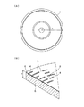
本発明が適用された光ディスク1の物理的な特性等について図1を参照して説明する。
The optical characteristics of the
光ディスク1は、BD(ブルーレイディスク 商標)と呼ばれているディスクであり、BDのうちのユーザにより書き込みができない再生専用のディスクである。光ディスク1は、図1(A)に示すように、半径Rが60mm、ディスク厚d12mmとされる。
The
再生のためのレーザ波長は405nmであり、いわゆる青紫色レーザが用いられる。対物レンズのNAは0.85である。 The laser wavelength for reproduction is 405 nm, and a so-called blue-violet laser is used. The NA of the objective lens is 0.85.
光ディスク1上には、図1(B)に示すように、ディスクの反射面である底面部3に、記録トラックに沿って凹部4が形成されることにより、信号が書き込まれている。すなわち、記録するデータのビット列に応じた凹凸の連続が、記録トラックに形成されている。以下、記録トラックの底面3に形成された凹部4のことを以下「ピット」と呼び、記録トラックの底面のピット以外の底面3のことを以下「ランド」と呼ぶものとする。
On the
また、光ディスク1は、ポリカーボネートやアクリル等の樹脂基板5上に、高い光反射特性を有する反射膜6が積層され、反射膜6の上に保護膜が積層された構成となっている。光ディスク1は、保護膜側からレーザ光が照射され、再生が行われる。
The
ここで、反射膜6は、通常の再生レベルのパワーのレーザ光を照射しても物質特性はなんら変化しない。しかしながら、再生レベルよりも充分に高い出力のレーザ光を照射すると溶融し、その部分がピット部分の反射特性と同等となる材料とされている。つまり、ランドは、高出力レーザ光が照射されると、ピットとみなされるような材料により構成されている。一般的な光記録媒体の場合、反射層はアルミニウムで形成されているが、光ディスク1では、反射層が例えばアルミニウムとチタンとの合金、アルミニウムと別元素を混ぜた合金、銀を含んだ合金等により構成されている。
Here, even if the
さらに、光ディスク1は、スタンパ等により凹凸(ランドとピット)のパタンが転写されて製造されるので、同一物が大量に生産される。光ディスク1は、パタン転写された後に、各ディスク固有の識別情報(以下、ユニークID又はUIDとも呼ぶ。)が、一枚一枚に記録される。その記録方法は、ディスクの記録トラック中の所定の位置に、高出力レーザを照射することによりランドをピット化することができる追記領域を、転写パタンとして予め複数設定しておき、ユニークIDの内容に応じて全ての追記領域のうちの所定の追記領域を選択し、選択した追記領域中の所定位置のランドを、高出力レーザを照射してピット化するという方法である。
Further, since the
光ディスクのフォーマット
光ディスク1は、記録されているデータが、所定の論理フォーマット及び所定の物理フォーマットにより管理されている。論理フォーマットでは、ユーザ情報に対してリード・ソロモン符号による誤り訂正符号化することが特徴である。また、物理フォーマットでは、誤り訂正符号化された情報に対して、1−7パリティ保存変調符号化及びNRZ-NRZI変換をすることが特徴である。
Format of optical disc In the
(論理フォーマット)
まず、論理フォーマットについて説明する。
(Logical format)
First, the logical format will be described.
光ディスク1の論理フォーマットでは、当該光ディスク1に記録する情報全体を、64キロバイトのデータ群に分割し、分割した各データ群に対して誤り検出、訂正コードを付加し、1つのECCクラスタと呼ぶデータの基本単位を形成する。
In the logical format of the
ECCクラスタの具体的な構成は次の通りである。まず、64kバイトのデータ群をさらに32個のデータ群に細分化して、図2に示すような2048バイトのデータ群を形成し、それぞれの2048バイトのデータ群に4バイトの誤り検出コード(EDC)を付加して、それぞれ合計2052バイトのデータ群にする。なお、誤り検出コード(EDC)の生成多項式は以下の数1の通りである。 The specific configuration of the ECC cluster is as follows. First, the 64 kbyte data group is further subdivided into 32 data groups to form 2048 byte data groups as shown in FIG. 2, and each 2048 byte data group has a 4-byte error detection code (EDC). ) To make a data group of 2052 bytes in total. Note that the error detection code (EDC) generator polynomial is as follows.

次に、この32個の2052バイトのデータ群単位で所定のスクランブルを施し、再度もとのデータ群(32×2052バイト)単位に戻す。次に、図3に示すように、この32×2052バイトのデータ群を、大きさが216バイトの304個のデータ群に再分割する。次に、再分割されたデータ群のそれぞれに、32バイトの誤り訂正コードを付加する。最後に、所定のインターリーブを行って並び替えて、ECCクラスタが完成する。 Next, predetermined scrambling is performed in units of 32 data groups of 2052 bytes, and the original data group (32 × 2052 bytes) is restored. Next, as shown in FIG. 3, the 32 × 2052 byte data group is subdivided into 304 data groups having a size of 216 bytes. Next, a 32-byte error correction code is added to each subdivided data group. Finally, rearrangement is performed by performing predetermined interleaving to complete the ECC cluster.
なお、ECCクラスタに付加する誤り訂正コードは、以下の数2の生成多項式で示すリード・ソロモン符号の符号化方式を用いている。 The error correction code to be added to the ECC cluster uses a Reed-Solomon code encoding method represented by the following generator polynomial.
リード・ソロモン符号では、バイト単位での誤り訂正が行われる。リード・ソロモン符号の誤り訂正可能なバイト数は、一般に、誤り訂正コードの個数の半分である。ECCクラスタでは、216バイトのデータ群に対して32バイトのリード・ソロモン符号の訂正コードを付加していることから、216バイト中最大16個のバイトのエラー訂正が可能である。密度にすると、16バイト/248バイトの誤りまでが訂正可能である。 In the Reed-Solomon code, error correction is performed in units of bytes. The number of bytes that can be error-corrected in a Reed-Solomon code is generally half the number of error-correcting codes. In the ECC cluster, since a 32-byte Reed-Solomon code correction code is added to a 216-byte data group, error correction of a maximum of 16 bytes out of 216 bytes is possible. In terms of density, errors of up to 16 bytes / 248 bytes can be corrected.
また、光ディスク1では、ECCクラスタの他に、BISクラスタと呼ばれるデータの単位がある。BISクラスタは、アドレスと呼ばれるECCクラスタの番号やECCクラスタ内のブロックの番号、及び、ユーザコントロールと呼ばれるECCクラスタに記録されている情報の機能を表す番号が記録されたデータ単位である。
In addition to the ECC cluster, the
BISクラスタの具体的な構成は次の通りである。まず、アドレス番号を示す4バイトの情報と、付加データである1バイトの情報と、4バイトのリード・ソロモン符号による誤り訂正コードとにより構成されたアドレスを形成する。次に、このような9バイトのアドレス情報と、21バイトのユーザコントロールとを組み合わせた30バイトのデータ群を24個形成する。次に、図4に示すように、この30バイトのデータ群に対してそれぞれ32バイトの誤り訂正コードを付加し、最後に所定のインターリーブを行って並び替えて、BISクラスタが完成する。BISクラスタに付加される誤り訂正コードの生成多項式は以下の数3に示す通りである。
The specific configuration of the BIS cluster is as follows. First, an address composed of 4-byte information indicating an address number, 1-byte information as additional data, and an error correction code using a 4-byte Reed-Solomon code is formed. Next, 24 30-byte data groups are formed by combining such 9-byte address information and 21-byte user control. Next, as shown in FIG. 4, a 32-byte error correction code is added to the 30-byte data group, and finally a predetermined interleaving is performed for rearrangement to complete the BIS cluster. The generation polynomial of the error correction code added to the BIS cluster is as shown in
(物理フォーマット)
続いて、物理フォーマットについて説明する。
(Physical format)
Next, the physical format will be described.
光ディスク1の物理層は、図5に示すように、ECCクラスタとBISクラスタを組み合わせたデータが記録されるフィジカルクラスタ部と、これらのフィジカルクラスタ部を接続する2つのリンキング部が繰り返し出現するように構成されている。
In the physical layer of the
フィジカルクラスタ部は、図6に示すように、それぞれ16個のアドレスユニットと呼ばれるブロックに分割され、さらに、各アドレスユニットが31個のデータフレームに分割されている。リンキング部は、2個のデータフレームで構成されている。 As shown in FIG. 6, the physical cluster part is divided into 16 blocks each called an address unit, and each address unit is further divided into 31 data frames. The linking unit is composed of two data frames.
データフレームは、図7(A)に示すように155バイトの情報が記録される。データフレームのデータは、39バイト目、78バイト目及び117バイト目の3バイトが、BISクラスタの情報であり、残りの152バイトがECCクラスタの情報である。なお、BISクラスタには、アドレスデータとユーザコントロールデータとが含まれているが、アドレスは、各アドレスユニット中の最初の3つのデータフレームのBISクラスタに含まれており、ユーザコントロールデータは、残りのデータフレームのBISクラスタに含まれている。 In the data frame, 155-byte information is recorded as shown in FIG. In the data of the data frame, 3 bytes of the 39th, 78th and 117th bytes are BIS cluster information, and the remaining 152 bytes are ECC cluster information. The BIS cluster includes address data and user control data, but the address is included in the BIS cluster of the first three data frames in each address unit, and the user control data remains. Are included in the BIS cluster of the data frame.
また、図7(B)に示すように、各データフレームでは、実データを、先頭を25ビットを1つのデータ群とし、残りを45ビット毎のデータ群とし、合計28個のデータ群に分割している。 As shown in FIG. 7B, in each data frame, the actual data is divided into a total of 28 data groups, with the first 25 bits being one data group and the remaining being a 45-bit data group. is doing.
データフレームは、図7(C)に示すように、先頭のみが、20ビットのフレーム同期信号と25ビットの実データと1ビットのDC制御ビットとから構成され、その他が、45ビットの実データと1ビットのDC制御ビットとから構成された、28個のDC制御ブロックに分割されている。 As shown in FIG. 7C, only the head of the data frame is composed of a 20-bit frame synchronization signal, 25-bit actual data, and 1-bit DC control bit, and the other is 45-bit actual data. Are divided into 28 DC control blocks, each of which is composed of 1 and a DC control bit.
なお、各ブロックの終端の1ビットのDC制御ビットは、変調後のビット値の0を−1に、1を1に対応させて加算して得られるDC成分の大きさを示す指標デジタルサムヴァリュー(DSV)の絶対値が0に近づくようにビット値が決定される。 The 1-bit DC control bit at the end of each block is an index digital sum value indicating the magnitude of a DC component obtained by adding 0 corresponding to the modulated bit value to -1 and 1 corresponding to 1. The bit value is determined so that the absolute value of (DSV) approaches zero.
(UID生成ビット列)
つぎに、UID生成ビット列について説明をする。
(UID generation bit string)
Next, the UID generation bit string will be described.
光ディスク1では、図8に示すように、媒体固有な識別情報の追記領域を形成するための所定ビット数(例えば12ビット(1−7パリティ保存変調する前において))のビット列(UID生成ビット列)を、所定のDC制御ブロック内に形成するように、記録データを構成しておく。すなわち、光ディスク1は、スタンパでディスク製造した後、高出力レーザを照射してユニークIDを追記するための追記領域を形成するために、所定の位置にUID生成ビット列が形成されている。
In the
このUID生成ビット列は、1-7パリティ保存変調及びNRZ-NRZI変換を行った後に、ピット-ランド-ピットの追記パタン(後で詳細に説明する。)を発生するためのビット列である。 This UID generation bit string is a bit string for generating a pit-land-pit additional recording pattern (described in detail later) after performing 1-7 parity storage modulation and NRZ-NRZI conversion.
UID生成ビット列は、全てのDC制御ブロックに設けるのではなく、ある特定のDC制御ブロックに対してのみである。例えば、所定の1つあるいは複数のフィジカルクラスタ部を選択し、そのうちの一部のデータフレームのDC制御ブロックに、UID生成ビット列を形成する。また、データフレームの全てのDC制御ブロックに対してではなく、一部のDC制御ブロックに対してのみUID生成ビット列を形成するようにする。 The UID generation bit string is not provided for all DC control blocks, but only for a specific DC control block. For example, one or a plurality of predetermined physical cluster portions are selected, and a UID generation bit string is formed in a DC control block of a part of the data frames. Also, the UID generation bit string is formed only for some DC control blocks, not for all DC control blocks of the data frame.
図8は、DC制御ブロック内におけるUID生成ビット列の形成位置を示した図である。 FIG. 8 is a diagram showing the formation position of the UID generation bit string in the DC control block.
UID生成ビット列は、DC制御ブロック内の所定の位置に形成されるようにする。 The UID generation bit string is formed at a predetermined position in the DC control block.
ここでは、UID生成ビット列を、DC制御ブロックのDC制御ビットを除く終端部分に位置するように設けている。このようにDC制御ブロックの終端部分にUID生成ビット列を設けることにより、BISクラスタに対して影響を与えないようにすることができる。 Here, the UID generation bit string is provided so as to be located at the end portion excluding the DC control bit of the DC control block. Thus, by providing the UID generation bit string at the terminal portion of the DC control block, it is possible to prevent the BIS cluster from being affected.
なお、図8では、DC制御ビットが2ビットとなっているが、これは、1-7パリティ保存変調が2ビット単位で変調されるために便宜上このように記している。 In FIG. 8, the DC control bit is 2 bits, but this is described in this way for convenience because 1-7 parity storage modulation is modulated in units of 2 bits.
例えば、UID生成ビット列が12ビット(変調前)である場合には、UID生成ビット列を形成する位置は、DC制御ブロックの先頭から33ビット目から44ビット目(変調前)までとなる。 For example, when the UID generation bit string is 12 bits (before modulation), the position where the UID generation bit string is formed is from the 33rd bit to the 44th bit (before modulation) from the top of the DC control block.
以上のようなUID生成ビット列は、当該UID生成ビット列を形成したことにより、光ディスク1が上記論理フォーマット及び物理フォーマットの規定外のディスクとならないようにする必要がある。
The UID generation bit string as described above needs to prevent the
ピット-ランド-ピットの追記パタン
つぎに、UID生成ビット列に対して、1-7パリティ保存変調及びNRZ-NRZI変換することにより発生されるピット-ランド-ピットの追記パタンについて説明をする。
Pit-Land-Pit Additional Recording Pattern Next, the pit-land-pit additional recording pattern generated by performing 1-7 parity storage modulation and NRZ-NRZI conversion on the UID generation bit string will be described.
上記UID生成ビット列に対して1-7パリティ保存変調及びNRZ-NRZI変換をすると、光ディスクの記録トラック上の複数の所定の位置に、図9(A)に示すように、ピット(凹部)-ランド(凸部)-ピット(凹部)のパタンが形成されることになる。 When 1-7 parity storage modulation and NRZ-NRZI conversion are performed on the UID generation bit string, as shown in FIG. 9A, pit (concave) -land at a plurality of predetermined positions on the recording track of the optical disk. A pattern of (convex) -pit (concave) is formed.
この追記パタンは、図9(B)に示すように真ん中のランド部分に対して高出力レーザを照射して当該ランドを溶融してピット化し、図9(C)に示すように全体としてピット(凹部)-ピット(凹部)-ピット(凹部)のパタンとすることにより、光ディスク1に対してユニークIDを記録するためのパタンである。
As shown in FIG. 9B, the additional write pattern is formed by irradiating the middle land portion with a high-power laser to melt the land to form pits, and as shown in FIG. A pattern for recording a unique ID on the
ここで、この追記パタンは、ピット-ランド-ピットの構成であればどのようなものでもよい、というわけではなく、以下のような条件が必要となる。 Here, the postscript pattern is not limited to any pit-land-pit configuration, and the following conditions are required.
(1)追記パタンは、ピット-ランド-ピットという凹凸パタンとなっている。 (1) The postscript pattern is an uneven pattern called pit-land-pit.
(2)追記パタンの長さは、1−7パリティ保護変調及びNRZ−NRZI変換後の最長符号長以下、1−7パリティ保護変調及びNRZ−NRZI変換の後の最短符号長の3倍以上である。すなわち、最長符号長が8T、最短符号長が2Tであるので(Tは、変調後ビット列の1ビットの長さである。)、追記パタンの長さは6T、7T又は8Tとなる。 (2) The length of the postscript pattern is not more than the longest code length after 1-7 parity protection modulation and NRZ-NRZI conversion, and not less than 3 times the shortest code length after 1-7 parity protection modulation and NRZ-NRZI conversion. is there. That is, since the longest code length is 8T and the shortest code length is 2T (T is the length of 1 bit of the modulated bit string), the length of the additional write pattern is 6T, 7T, or 8T.
(3)追記パタンの前後の変調後ビット列は、当該追記パタンが、全てピットで構成されたパタンに置き換わったときにも、変調後ビット列の全体が1−7パリティ保護変調及びNRZ−NRZI変換後の規則に従うように生成されている。 (3) The post-modulation bit string before and after the post-recording pattern has the entire post-modulation bit string after 1-7 parity protection modulation and NRZ-NRZI conversion even when the post-recording pattern is replaced with a pattern composed entirely of pits. It is generated to follow the rules.
以上のような条件に従った追記パタンを形成すると、真ん中のランドが溶融してピット化した後も、光ディスク1には1-7パリティ保存変調に従ったデータが記録されていることとなる。すなわち、ランドをピット化したことにより前後のパタンとの関係が1−7パリティ保存変調から外れるビット列とはならなくなる。
When the write-once pattern according to the above conditions is formed, data according to 1-7 parity storage modulation is recorded on the
以上のような条件の追記パタンとして、具体的には次のようなピット-ランド-ピットのパタンがある。 Specifically, there are the following pit-land-pit patterns as additional patterns under the above conditions.
4T-2T-2T,2T-4T-2T,2T-2T-4T,2T-3T-3T,3T-2T-3T,3T-3T-2T,3T-2T-2T,2T-3T-2T,2T-2T-3T,2T-2T-2T
なお、ここで、Tは、1つの変調後ビット列のビット長である。
4T-2T-2T, 2T-4T-2T, 2T-2T-4T, 2T-3T-3T, 3T-2T-3T, 3T-3T-2T, 3T-2T-2T, 2T-3T-2T, 2T- 2T-3T, 2T-2T-2T
Here, T is the bit length of one modulated bit string.
特に、ピット−ランド−ピットの追記パタンの真ん中のランドが2Tであると、2Tが1-7パリティ保存変調の最小符号長であり、溶融のためのエネルギーが最も少なくて済み効率的である。 In particular, if the land in the middle of the pit-land-pit write-on pattern is 2T, 2T is the minimum code length of 1-7 parity storage modulation, and the energy for melting is the least and efficient.
さらに、3T-2T-3Tのパタンは、ピット−ランド−ピットの追記パタンの真ん中のランドが2Tであるため1−7パリティ保存変調における最小符号長であり、溶融のためのエネルギーが最も少なく済むとともに、追記位置の前後に対するポジションマージンが最も広いので、非常に望ましい形状の追記パタンである。 Furthermore, the 3T-2T-3T pattern has the minimum code length in 1-7 parity storage modulation because the center land of the pit-land-pit additional recording pattern is 2T, and requires the least energy for melting. In addition, since the position margin with respect to the front and rear of the additional recording position is the widest, the additional recording pattern has a very desirable shape.
また、4T-2T-2Tのパタンは、ピット−ランド−ピットの追記パタンの真ん中のランドが2Tであるため1−7パリティ保存変調における最小符号長であり、溶融のためのエネルギーが最も少なく済むとともに、追記時における余熱の利用効率が高く、非常に望ましい形状の追記パタンである。 The 4T-2T-2T pattern is the minimum code length in 1-7 parity storage modulation because the middle land of the pit-land-pit additional recording pattern is 2T, and it requires the least energy for melting. At the same time, the additional heat utilization efficiency at the time of additional recording is high, and it is a highly desirable additional recording pattern.
UID生成ビット列の具体例
つぎに、3T-2T-3T及び4T-2T-2Tを生成するための12ビット(変調前)のUID生成ビット列の具体例について説明をする。
Specific Example of UID Generation Bit String Next, a specific example of a 12-bit (before modulation) UID generation bit string for generating 3T-2T-3T and 4T-2T-2T will be described.
まず、1-7パリティ保存変調について説明をする。 First, 1-7 parity storage modulation will be described.
図10は、1-7パリティ保存変調の変調テーブルを示している。図10におけるxxは、xが0か1のいずれかの値を任意に取るものを意味する。また、図10における(-fs)はフレームシンクのビット列を表しているものとする。 FIG. 10 shows a modulation table for 1-7 parity storage modulation. Xx in FIG. 10 means that x takes any value of 0 or 1. Further, (-fs) in FIG. 10 represents a bit string of a frame sync.
図11は、フレーム同期信号を示している。図11における#は、このフレームシンクになる前の変調前のビット列が“00”、あるいは、“0000”であったときのみに、1となって、それ以外では0となる。 FIG. 11 shows the frame synchronization signal. 11 in FIG. 11 becomes 1 only when the bit string before modulation before the frame sync is “00” or “0000”, and 0 otherwise.
以上の1-7パリティ保存変調の変調テーブルを参照しながら、以下、3T-2T-3T及び4T-2T-2Tを生成するための12ビット(変調前)のUID生成ビット列の内容について説明をする。 The content of the 12-bit (before modulation) UID generation bit string for generating 3T-2T-3T and 4T-2T-2T will be described below with reference to the modulation table for 1-7 parity storage modulation. .
(3T-2T-3T)
まず、3T-2T-3Tについて説明をする。
(3T-2T-3T)
First, 3T-2T-3T will be described.
図12は、光ディスク1におけるユニークIDを記録するための3T-2T-3T(ピット-ランド-ピット)の追記パタンを形成するための12ビットのUID生成用ビット列を示している。
FIG. 12 shows a 12-bit UID generation bit string for forming a 3T-2T-3T (pit-land-pit) additional recording pattern for recording a unique ID on the
12ビットのUID生成用ビット列は、図12に示すように、先頭の2ビットの変調終端ビット列(Termination)と、次の2ビットの極性制御ビット列(polarity control)と、最後の8ビットのUIDビット列(UID Bit)とから構成されている。なお、図12中のUIDビット列の後ろにある2ビットのビット列(parity)は、DC制御ビットを発生するためのビット列である。 As shown in FIG. 12, the 12-bit UID generation bit string includes a leading 2-bit modulation termination bit string (Termination), a next 2-bit polarity control bit string (polarity control), and a final 8-bit UID bit string. (UID Bit). A 2-bit bit string (parity) after the UID bit string in FIG. 12 is a bit string for generating a DC control bit.
1−7パリティ保存変調では変調単位が一定でないため、3T-2T-3Tのピット-ランド-ピットの追記パタンの発生を損なわないように、この追記パタンの直前にあるデータの変調単位の終端を用意する必要がある。12ビットのUID生成用ビット列のうちの1番目、2番目の2ビットである変調終端ビット列(Termination)は、当該UIDビット列の直前にあるデータの変調単位の最後の部分を決める部分に相当する。すなわち、直前のビット列の1−7パリティ保存変調をきちんと終わらせて、直前のビット列の影響を、後ろ変調終端ビット列及びUIDビット列の変調にまで与えないようにするためのビット列となる。 Since the modulation unit is not constant in 1-7 parity storage modulation, the end of the modulation unit of the data immediately before this additional recording pattern is set so as not to impair the generation of the 3T-2T-3T additional pit-land-pit pattern. It is necessary to prepare. The modulation termination bit string (Termination), which is the first and second two bits of the 12-bit UID generation bit string, corresponds to a part that determines the last part of the modulation unit of data immediately before the UID bit string. That is, the 1-7 parity storage modulation of the immediately preceding bit string is completed properly, and the bit string is used to prevent the influence of the immediately preceding bit string from affecting the modulation of the rear modulation termination bit string and the UID bit string.
変調終端ビット列(Termination)は、具体的には、図10の変調前ビット列の終端2ビットを参照してわかるように、01,10,11のいずれかとなる。
Specifically, the modulation termination bit string (Termination) is any one of 01, 10, and 11 as can be seen by referring to the
12ビットのUID生成用ビット列のうち5番目から12番目の8ビットは、3T-2T-3Tのパタンを発生するためのUIDビットである。 The 5th to 12th 8 bits in the 12-bit UID generation bit string are UID bits for generating a 3T-2T-3T pattern.
UIDビットは、具体的には、図10の変調後ビット列から探しだすと、 “01000001”となる。なお、5番目から12番目の8ビットのUIDビットは、4ビット目までで変調が終端されていることを前提として1-7パリティ保存変調を行う。このことにより、UIDビットを1−7パリティ保存変調することにより発生するビット列は、“010-010-100-100”となる。これをさらに、NRZ-NRZI変換を行うと、“001-110-011-100”となる。このNRZ-NRZI変換後のビット列の値の0、1が、それぞれランド、ピットが対応する。NRZ-NRZI変換後のビット列は、2T-3T-2T-3T-2Tとなる。このパタンをみると、3ビット目から10ビット目までのパタンが、3T-2T-3Tのパタンとなっていることがわかる。すなわち、この3T-2T-3Tのパタンが、追記パタンとなる。従って、ピット−ランド−ピットの追記パタンのピット部分は、1−7パリティ保存変調及びNRI-NRZI変換後の57,58ビット目となる。
Specifically, the UID bit is “01000001” when searched from the modulated bit string of FIG. Note that the 5th to 12th UID bits are subjected to 1-7 parity storage modulation on the assumption that the modulation is terminated up to the 4th bit. As a result, the bit string generated by 1-7 parity storage modulation of the UID bits is “010-010-100-100”. When this is further subjected to NRZ-NRZI conversion, "001-110-011-100" is obtained. The
12ビットのUID生成用ビット列のうち3番目、4番目のビットである極性制御ビット列(polarity control)は、1番目、2番目のビットを1−7パリティ保存変調及びNRZ-NRZI変換したあとの最後のビットがピットであるかランドであるかに応じて、後段で生成される3T-2T-3Tの追記パタンがピット-ランド-ピットとなるように、ビット値が制御される極性制御ビットとなる。 Of the 12-bit UID generation bit string, the third and fourth bits, the polarity control bit string (polarity control), are the last after 1-7 parity storage modulation and NRZ-NRZI conversion of the first and second bits. Depending on whether the bit is a pit or a land, it becomes a polarity control bit whose bit value is controlled so that the postscript pattern of 3T-2T-3T generated in the subsequent stage becomes a pit-land-pit .
つまり、UIDビットにより発生される3T-2T-3Tパタンだけでは、ランの長さは決定されるが、NRZ-NRZI変換の影響により、ピット-ランド-ピットになるか、それともランド-ピット-ランドかは、確実ではない。 In other words, the run length is determined only by the 3T-2T-3T pattern generated by the UID bit, but it becomes pit-land-pit or lands-pit-land due to the influence of NRZ-NRZI conversion. I am not sure.
そのため、最初の2ビットの変調終端ビット列までで1−7パリティ保存変調を終了することができると、最初の2ビットまでの時点におけるビット値が、ランドに対応するのか、ピットに対応するのかの極性を決定することができることを利用し、極性制御ビット列(polarity control)によって、上記の3T-2T-3Tのパタンが、ピット-ランド-ピットになるか、それともランド-ピット-ランドのパタンになるかを制御している。 Therefore, if the 1-7 parity storage modulation can be completed up to the first 2-bit modulation end bit string, whether the bit values at the time up to the first 2 bits correspond to lands or pits? Utilizing the fact that polarity can be determined, the above 3T-2T-3T pattern becomes a pit-land-pit or a land-pit-land pattern by polarity control bit string (polarity control) Is controlling.
具体的には、極性制御ビット列(polarity control)が、“01”又は“11”の場合には、2回極性が反転する。また、“10”の場合には、1回極性が反転する。従って、変調終端ビット列の変調が終了した時点のビットがランドであれば、極性制御ビット列(polarity control)は“10”となり、変調終端ビット列の変調が終了した時点のビットがピットであれば、極性制御ビット列(polarity control)は“01”又は“11”となる。 Specifically, when the polarity control bit string (polarity control) is “01” or “11”, the polarity is inverted twice. In the case of “10”, the polarity is reversed once. Therefore, if the bit at the time when the modulation of the modulation termination bit string is completed is a land, the polarity control bit string (polarity control) is “10”, and if the bit at the time of completion of the modulation of the modulation termination bit string is a pit, the polarity The control bit string (polarity control) is “01” or “11”.
なお、図10の1−7パリティ保存変調の変調テーブルから確認できるように、1−7パリティ保存変調では、2ビットのビット列01,10、11が、それぞれ必ず変調の単位の最後となるようなビットとは限らない。例えば、01であれば、後ろに来るビットが11であれば変調の最後とはならず、また、10であればうしろに来るビットが11であれば変調の最後とはならず、また、11であればうしろに来るビットが0111であれば変調の最後とはならない。 As can be confirmed from the modulation table of 1-7 parity storage modulation in FIG. 10, in the 1-7 parity storage modulation, the 2-bit bit strings 01, 10 and 11 are always the last of the modulation unit. Not necessarily a bit. For example, if it is 01, the last bit is 11 if it is 11, it will not be the end of modulation, if it is 10, if it is 11 after it, it will not be the end of modulation, If it is 11 and the next bit is 0111, it will not be the end of modulation.
従って、12ビットのUID生成用ビット列では、(1)極性を決定するため、極性制御のビットの直前のビットがそれまでのデータに対する変調の末尾になっている、(2)常に3T-2T-3Tのパタンを発生するため、前記パタンを変調する前に極性制御ビットそのものも変調データの末尾となって変調が施されている、ことも必要である。 Accordingly, in the 12-bit UID generation bit string, (1) in order to determine the polarity, the bit immediately before the polarity control bit is the end of the modulation for the data so far. (2) Always 3T-2T- In order to generate a 3T pattern, it is also necessary that the polarity control bit itself be modulated at the end of the modulation data before the pattern is modulated.
(3T-2T-3Tを発生するための具体的な値)
具体的に、3T-2T-3T(ピット-ランド-ピット)を発生する以上の条件を満足した12ビットのUID生成用ビット列として、次の8通りのビット列が挙げられる。
(Specific values for generating 3T-2T-3T)
Specifically, the following eight bit strings are listed as 12-bit UID generation bit strings that satisfy the above conditions for generating 3T-2T-3T (pit-land-pit).
(A群)0x541、0x641、0x941、0xA41、0xD41、0xE41
(B群)0xB41,0xf41
なお、0x○○○とは、“○○○”の部分が16進数の表記であることを表している。
(Group A) 0x541, 0x641, 0x941, 0xA41, 0xD41, 0xE41
(Group B) 0xB41, 0xf41
In addition, 0xxxx means that the "xxx" part is in hexadecimal notation.
(A群)は、12ビットのうちの最初の2ビットまでを変調したあとの変調後ビットの極性を反転させるタイプであり、(B群)は、12ビットのうちの最初の2ビットまでを変調したあとの変調後ビット列の極性を保持するタイプである。 (Group A) is a type that inverts the polarity of the modulated bits after modulating up to the first 2 bits of 12 bits, and (Group B) is up to the first 2 bits of 12 bits. This type retains the polarity of the modulated bit string after modulation.
従って、12ビットのうちの最初の2ビットまでを変調したあとの変調後ビットの極性を反転させる場合には、(A群)のうちの1つのビット列を選択して変調前ビット列に挿入し、極性を保持する場合には、(B群)のうちの1つのビット列を変調前ビット列に挿入すればよい。 Therefore, when inverting the polarity of the modulated bit after modulating the first 2 bits of the 12 bits, select one bit string (group A) and insert it into the pre-modulation bit string, In order to maintain the polarity, one bit string in (group B) may be inserted into the pre-modulation bit string.
このように変調前ビット列に以上の12ビットのUID生成用ビット列を挿入する処理をすることにより、DCブロック内の所定の位置に、3T-2T-3T(ピット-ランド-ピット)の追記パタンを形成することができる。 In this way, by adding the above 12-bit UID generation bit string to the pre-modulation bit string, a 3T-2T-3T (pit-land-pit) additional recording pattern is added to a predetermined position in the DC block. Can be formed.
また、(A群)、(B群)から一つずつ選び、次のように
(a) (A)0x941、(B)0xB41
(b) (A)0xA41、(B)0xB41
(c) (A)0xD41、(B)0xF41
(d) (A)0xE41、(B)0xF41
(a)〜(d)の4通りのペアを生成する。
Also, one by one is selected from (Group A) and (Group B), and (a) (A) 0x941 and (B) 0xB41 are as follows:
(B) (A) 0xA41, (B) 0xB41
(C) (A) 0xD41, (B) 0xF41
(D) (A) 0xE41, (B) 0xF41
Four types of pairs (a) to (d) are generated.
各ペアは、第3番目のビットのみが異なるペアとなっている。 Each pair is a different pair only in the third bit.
これらのビット列のうち、たとえば1−7パリティ保存変調を施す直前の情報ビット列に対して、いずれか一つが所定の位置に配置されているものとする。 Of these bit strings, for example, one of the information bit strings immediately before the 1-7 parity storage modulation is performed is arranged at a predetermined position.
そして、1−7パリティ保存変調によって、上記の情報の2ビット目までを塊として、変調がなされたのち、3T-2T-3Tの追記パタンがピット-ランド-ピットとなるか否かを調べ、ピット-ランド-ピットとなる場合には3番目のビットをそのまま保持する。ピット-ランド-ピットとならない場合には3番目のビットを反転する。すなわち、ペアとなっている他方のビット列に置き換える。 Then, by 1-7 parity storage modulation, after modulation is performed up to the second bit of the above information, it is checked whether or not the 3T-2T-3T additional write pattern becomes a pit-land-pit, In case of pit-land-pit, the third bit is held as it is. If not pit-land-pit, the third bit is inverted. That is, the other bit string in the pair is replaced.
以上のように、光ディスク1への記録データ列を生成する際に、最初の2ビットでこの部分までの極性を決定して、次の2ビットでこの部分からの極性を制御して、3T-2T-3Tのパタンの真ん中の2Tがランドになる、という3つのステップを完了して、所定の位置(例えば、DCブロックの最後の部分)に3T-2T-3Tのピット-ランド-ピットのパタンを発生することができる。
As described above, when generating a data string to be recorded on the
図13は、上述の4種類のペアとして出現している、0x941、0xB41、0xA41、0xD41、0xF41、0xE41について、これを1−7パリティ保存変調して、識別情報UID=1を記録した結果と、これを復調した後の情報を表した表である。 FIG. 13 shows the result of recording the identification information UID = 1 by performing 1-7 parity storage modulation on 0x941, 0xB41, 0xA41, 0xD41, 0xF41, and 0xE41 appearing as the above four types of pairs. It is the table | surface showing the information after demodulating this.
この表において左端の第一コラムは、上述の4種類のペアとして出現する6種類のUID生成ビット列である。これらは、2ビット目までを変調した際のランド、ピットの極性の情報に応じて、3T-2T-3Tの組み合わせの2Tの部分がランドになるように選択されるものである。 In the table, the first column at the left end is six types of UID generation bit strings that appear as the above four types of pairs. These are selected so that the 2T portion of the combination of 3T-2T-3T becomes a land according to the information on the polarity of the land and pit when the second bit is modulated.
第二コラムは、第一コラムのUID生成ビット列を図10の変調テーブルを用いて変調した結果である。また、第三コラムは、発生した3T-2T-3Tのピット-ランド-ピットの組み合わせのランド部分に追記を行った結果、8Tのピットが発生したことを表している。ここで、第二コラムと第三コラムの間では、変調結果をピット、ランドに対応付けるためのNRZI変換とその逆変換があるが、ここでは省略してある。 The second column is the result of modulating the UID generation bit string of the first column using the modulation table of FIG. The third column shows that 8T pits are generated as a result of additional writing to the land portion of the generated 3T-2T-3T pit-land-pit combination. Here, between the second column and the third column, there is an NRZI conversion for associating the modulation result with the pits and lands and its inverse conversion, but they are omitted here.
第四コラムは、第三コラムを1−7パリティ保存復調した結果である。第四コラムでは、候補となる情報がおのおの二つずつ存在している。これは、固有情報を記録する領域のうしろに来ている情報が何であるかによって決定される。 The fourth column is a result of 1-7 parity storage demodulation of the third column. In the fourth column, there are two candidate information items. This is determined by what information is behind the area for recording the unique information.
この表では、真ん中より左側の部分を追記が無い場合の識別情報領域のビット列(UID=0)、また、真ん中より左側の部分を追記がある場合の識別情報領域のビット列(UID=1)とみることもできる。すなわち、この表をもちいれば、識別情報のビット値0、1とそのときの識別情報領域におけるビット列のパタンとの対応関係を確認することができる。 In this table, the bit string (UID = 0) in the identification information area when the left part from the middle is not added, and the bit string (UID = 1) in the identification information area when the part to the left from the middle is added. You can also see it. That is, if this table is used, it is possible to confirm the correspondence between the bit values 0 and 1 of the identification information and the pattern of the bit string in the identification information area at that time.
(4T-2T-2T)
つぎに、4T-2T-2Tについて説明をする。
(4T-2T-2T)
Next, 4T-2T-2T will be described.
図14は、光ディスク1におけるユニークIDを記録するための4T-2T-2T(ピット-ランド-ピット)の追記パタンを形成するための12ビットのUID生成用ビット列を示している。
FIG. 14 shows a 12-bit UID generation bit string for forming a 4T-2T-2T (pit-land-pit) write-once pattern for recording a unique ID on the
12ビットのUID生成用ビット列は、図14に示すように、先頭の2ビットの変調終端ビット列(Termination)と、次の2ビットの極性制御ビット列(polarity control)と、最後の8ビットのUIDビット列(UID Bit)とから構成されている。なお、図14中のUIDビット列の後ろにある2ビットのビット列(parity)は、DC制御ビットを発生するためのビット列である。 As shown in FIG. 14, the 12-bit UID generation bit string includes the first 2-bit modulation termination bit string (Termination), the next 2-bit polarity control bit string (polarity control), and the last 8-bit UID bit string. (UID Bit). Note that a 2-bit bit string (parity) after the UID bit string in FIG. 14 is a bit string for generating a DC control bit.
先頭の2ビットの変調終端ビット列(Termination)及び次の2ビットの極性制御ビット列(polarity control)の機能や内容は、3T-2T-3Tのパタンと同様である。 The functions and contents of the leading 2-bit modulation termination bit string (Termination) and the next 2-bit polarity control bit string (polarity control) are the same as the 3T-2T-3T pattern.
12ビットのUID生成用ビット列のうち5番目から12番目の8ビットは、4T-2T-2Tのパタンを発生するためのUIDビットである。 The 5th to 12th 8 bits in the 12-bit UID generation bit string are UID bits for generating a 4T-2T-2T pattern.
UIDビットは、具体的には、図10の変調後ビット列から探しだすと、“01100011”となる。なお、5番目から12番目の8ビットのUIDビットは、4ビット目までで変調が終端されていることを前提として1-7パリティ保存変調を行う。このことにより、UIDビットを1−7パリティ保存変調することにより発生するビット列は、“010-001-010-100”となる。これをさらに、NRZ-NRZI変換を行うと、“001-111-001-100”となる。このNRZ-NRZI変換後のビット列の値の0、1が、それぞれランド、ピットが対応する。NRZ-NRZI変換後のビット列は、2T-4T-2T-2T-2Tとなる。このパタンをみると、3ビット目から10ビット目までのパタンが、4T-2T-2Tのパタンとなっていることがわかる。すなわち、この4T-2T-2Tのパタンが、追記パタンとなる。従って、ピット−ランド−ピットの追記パタンのピット部分は、1−7パリティ保存変調及びNRI-NRZI変換後の58,59ビット目となる。
Specifically, the UID bit is “01100011” when searched from the modulated bit string of FIG. Note that the 5th to 12th UID bits are subjected to 1-7 parity storage modulation on the assumption that the modulation is terminated up to the 4th bit. As a result, the bit string generated by performing 1-7 parity storage modulation on the UID bits is “010-001-010-100”. If this is further subjected to NRZ-NRZI conversion, "001-111-001-100" is obtained. The
(4T-2T-2Tを発生するための具体的な値)
具体的に、4T-2T-2T(ピット-ランド-ピット)を発生する以上の条件を満足した12ビットのUID生成用ビット列として、次の8通りのビット列が挙げられる。
(Specific values for generating 4T-2T-2T)
Specifically, the following eight bit strings are listed as 12-bit UID generation bit strings that satisfy the above conditions for generating 4T-2T-2T (pit-land-pit).
(A群)0x563、0x663、0x963、0xA63、0xD63、0xE63
(B群)0xB63,0xf63
なお、0x○○○とは、“○○○”の部分が16進数の表記であることを表している。
(Group A) 0x563, 0x663, 0x963, 0xA63, 0xD63, 0xE63
(Group B) 0xB63, 0xf63
In addition, 0xxxx means that the "xxx" part is in hexadecimal notation.
このとき、(A群)は、12ビットのうちの最初の2ビットまでを変調したあとの変調後ビットの極性を反転させるタイプであり、(B群)は、12ビットのうちの最初の2ビットまでを変調したあとの変調後ビット列の極性を保持するタイプである。 At this time, (Group A) is a type that inverts the polarity of the modulated bits after modulating the first 2 bits of 12 bits, and (Group B) is the first 2 bits of 12 bits. This type retains the polarity of the modulated bit string after modulating up to bits.
従って、12ビットのうちの最初の2ビットまでを変調したあとの変調後ビットの極性を反転させる場合には、(A群)のうちの1つのビット列を選択して変調前ビット列に挿入し、極性を保持する場合には、(B群)のうちの1つのビット列を変調前ビット列に挿入すればよい。 Therefore, when inverting the polarity of the modulated bit after modulating the first 2 bits of the 12 bits, select one bit string (group A) and insert it into the pre-modulation bit string, In order to maintain the polarity, one bit string in (group B) may be inserted into the pre-modulation bit string.
このように変調前ビット列に以上の12ビットのUID生成用ビット列を挿入する処理をすることにより、DCブロック内の所定の位置に、4T-2T-2T(ピット-ランド-ピット)の追記パタンを形成することができる。 In this way, by inserting the above 12-bit UID generation bit string into the pre-modulation bit string, a 4T-2T-2T (pit-land-pit) additional write pattern is placed at a predetermined position in the DC block. Can be formed.
また、(A群)、(B群)から一つずつ選び、次のように
(a) (A)0x963、(B)0xB63
(b) (A)0xA63、(B)0xB63
(c) (A)0xD63、(B)0xF63
(d) (A)0xE63、(B)0xF63
(a)〜(d)の4通りのペアを生成する。
Also, one by one is selected from (Group A) and (Group B), and (a) (A) 0x963 and (B) 0xB63 are as follows:
(B) (A) 0xA63, (B) 0xB63
(C) (A) 0xD63, (B) 0xF63
(D) (A) 0xE63, (B) 0xF63
Four types of pairs (a) to (d) are generated.
各ペアは、第3番目のビットのみが異なるペアとなっている。 Each pair is a different pair only in the third bit.
これらのビット列のうち、たとえば1−7パリティ保存変調を施す直前の情報ビット列に対して、いずれか一つが所定の位置に配置されているものとする。 Of these bit strings, for example, one of the information bit strings immediately before the 1-7 parity storage modulation is performed is arranged at a predetermined position.
そして、1−7パリティ保存変調によって、上記の情報の2ビット目までを塊として、変調がなされたのち、4T-2T-2Tの追記パタンがピット-ランド-ピットとなるか否かを調べ、ピット-ランド-ピットとなる場合には3番目のビットをそのまま保持する。ピット-ランド-ピットとならない場合には3番目のビットを反転する。すなわち、ペアとなっている他方のビット列に置き換える。 Then, after 1-7 parity storage modulation, modulation up to the second bit of the above information is performed, and after that, it is checked whether or not the 4T-2T-2T additional write pattern becomes a pit-land-pit, In case of pit-land-pit, the third bit is held as it is. If not pit-land-pit, the third bit is inverted. That is, the other bit string in the pair is replaced.
以上のように、光ディスク1への記録データ列を生成する際に、最初の2ビットでこの部分までの極性を決定して、次の2ビットでこの部分からの極性を制御して、4T-2T-2Tのパタンの真ん中の2Tがランドになる、という3つのステップを完了して、所定の位置(例えば、DCブロックの最後の部分)に4T-2T-2Tのピット-ランド-ピットのパタンを発生することができる。
As described above, when generating the recording data string to the
図15は、上述の4種類のペアとして出現している、0x961、0xB61、0xA61、0xD61、0xF61、0xE61について、これを1−7パリティ保存変調して、識別情報UID=1を記録した結果と、これを復調した後の情報を表した表である。 FIG. 15 shows the result of recording the identification information UID = 1 by performing 1-7 parity storage modulation on 0x961, 0xB61, 0xA61, 0xD61, 0xF61, and 0xE61 appearing as the above four types of pairs. It is the table | surface showing the information after demodulating this.
この表において左端の第一コラムは、上述の4種類のペアとして出現する6種類のUID生成ビット列である。これらは、2ビット目までを変調した際のランド、ピットの極性の情報に応じて、4T-2T-2Tの組み合わせの2Tの部分がランドになるように選択されるものである。 In the table, the first column at the left end is six types of UID generation bit strings that appear as the above four types of pairs. These are selected so that the 2T portion of the combination of 4T-2T-2T becomes a land according to the information on the polarity of the land and pit when the second bit is modulated.
第二コラムは、第一コラムのUID生成ビット列を図10の変調テーブルを用いて変調した結果である。また、第三コラムは、発生した4T-2T-2Tのピット-ランド-ピットの組み合わせのランド部分に追記を行った結果、8Tのピットが発生したことを表している。ここで、第二コラムと第三コラムの間では、変調結果をピット、ランドに対応付けるためのNRZI変換とその逆変換があるが、ここでは省略してある。 The second column is the result of modulating the UID generation bit string of the first column using the modulation table of FIG. The third column indicates that 8T pits are generated as a result of additional writing to the land portion of the generated 4T-2T-2T pit-land-pit combination. Here, between the second column and the third column, there is an NRZI conversion for associating the modulation result with the pits and lands and its inverse conversion, but they are omitted here.
第四コラムは、第三コラムを1−7パリティ保存復調した結果である。第四コラムでは、候補となる情報がおのおの二つずつ存在している。これは、固有情報を記録する領域のうしろに来ている情報が何であるかによって決定される。 The fourth column is a result of 1-7 parity storage demodulation of the third column. In the fourth column, there are two candidate information items. This is determined by what information is behind the area for recording the unique information.
この表では、真ん中より左側の部分を追記が無い場合の識別情報領域のビット列(UID=0)、また、真ん中より左側の部分を追記がある場合の識別情報領域のビット列(UID=1)とみることもできる。すなわち、この表をもちいれば、識別情報のビット値0、1とそのときの識別情報領域におけるビット列のパタンとの対応関係を確認することができる。 In this table, the bit string (UID = 0) in the identification information area when the left part from the middle is not added, and the bit string (UID = 1) in the identification information area when the part to the left from the middle is added. You can also see it. That is, if this table is used, it is possible to confirm the correspondence between the bit values 0 and 1 of the identification information and the pattern of the bit string in the identification information area at that time.
光ディスク1の製造方法
次に、光ディスク1の製造方法について説明する。
Manufacturing Method of
図16に示すように、光ディスク1の製造方法は、レジスト塗布工程S11、カッティング工程S12、現像定着工程S13、金属原盤作成工程S14を経て金属原盤の作成が行われる。
As shown in FIG. 16, in the manufacturing method of the
ここで、レジスト塗布工程S11は、ガラス原盤にフォトレジストを塗布する工程であり、カッティング工程S12は、フォトレジストにビット列に応じてスイッチングされるレーザを照射して凹凸のパタンを記録する工程である。現像定着工程S13は、原盤上で上記凹凸のパタンを記録したレジストを現像処理して原盤上に定着処理する工程であり、金属原盤作成工程S14は、上記原盤に表面に電解めっきを施こして金属原盤を作成する工程である。 Here, the resist coating step S11 is a step of applying a photoresist to the glass master, and the cutting step S12 is a step of recording an uneven pattern by irradiating the photoresist with a laser switched according to a bit string. . The development fixing step S13 is a step of developing and fixing the resist on which the concave / convex pattern is recorded on the master, and the metal master creating step S14 performs electrolytic plating on the surface of the master. This is a process of creating a metal master.
次に、作成された金属原盤をもとに、スタンパ作成工程S15、基板形成工程S16を経て、ディスク基板が形成される。ここで、スタンパ作成工程S15とは、金属原盤を元にスタンパを製造する工程であり、また、基板形成工程S16は、成形金型内にスタンパを配置して、射出成型機を用いてポリカーボネートやアクリル等の透明樹脂によりディスク基板を形成する工程である。 Next, a disk substrate is formed through a stamper creation step S15 and a substrate formation step S16 based on the created metal master. Here, the stamper creation step S15 is a step of manufacturing a stamper based on a metal master, and the substrate formation step S16 is a step of placing a stamper in a molding die and using an injection molding machine to produce polycarbonate or In this step, the disk substrate is formed of a transparent resin such as acrylic.
このように作製されたディスク基板には、カッティング工程S12で原盤に形成されたランドとピットのパタンが転写されている。 The land and pit patterns formed on the master in the cutting step S12 are transferred to the disk substrate thus manufactured.
次に、反射膜形成工程S17、保護膜塗布18を経て、再生専用の光ディスク1が製造される。反射膜形成工程S17では、ディスク基板のピットパタンが形成された面に、スパッタ等により反射膜が形成される。光ディスク1は、この反射膜に媒体固有識別情報を記録する。なお、光ディスク1を作成するためには、この反射膜は、通常のビット情報以外に、熱記録によって媒体固有識別情報も記録できる反射膜でなければならない。したがって、この反射膜には、一般的な反射膜の組成となるアルミニウムのほかに、例えばチタン等の別の元素を混ぜて合金とした反射膜を用いる。保護膜塗布工程S18では、保護膜が形成される。この工程は、反射膜上に紫外線硬化型樹脂をスピンコートによって塗布して、紫外線を照射することによってなされる。なお、このように形成された光ディスク1は、保護膜側から読み取り用のレーザ光を照射して情報の再生が行うことができる。
Next, the read-only
次に、再生専用の光ディスク1が作成されると、UIDカッティング工程19が行われる。このUIDカッティング工程19では、各追記領域上のピット-ランド-ピットの追記パタンの真ん中のランドに高出力レーザ光を照射して、作成された光ディスク1の一枚一枚に対して個別のユニークIDを書き込んでいく。
Next, when the read-only
このことにより、各光ディスク1の一枚一枚に対してユニークIDが書き込まれた光ディスク1が製造される。
As a result, the
UIDカッティング工程19で用いられるUIDカッティング装置20について、図17を参照して説明をする。
The
UIDカッティング装置20は、大量に生産された同一の光ディスク1に対して、それぞれ個々のユニークIDを追加記録する装置である。
The
UIDカッティング装置20は、図17に示すように、光ディスク1に対して通常の再生時より充分高いエネルギのレーザ光を照射して、UIDを追記することができるピット-ランド-ビットの追記パタンのランド部分を溶融させるUIDライタ21と、光ディスク1に記録されている信号を読み出してピット-ランド-ビットの追記パタンの位置を検出するUID検出部22と、ユニークIDを発生するUID発生部23と、光ディスク1を回転駆動する駆動部24とを備えている。
As shown in FIG. 17, the
UIDライタ21では、UID発生部23から発生されるユニークIDのビット列に応じて、追記パタンに照射するためのレーザ光がスイッチングされる。UID発生部23は、例えばコンピュータなどに配置されている外部記憶装置から出力される変調済みのビット列である。
In the
UIDカッティング装置20では、駆動部24が光ディスク1をゆっくりと回転させる。このとき、レーザ光が光ディスク1の記録トラックに沿ってゆっくりとトレースされる。その結果、UID検出部22が記録トラック上の所定の位置のピット-ランド-ビットの追記パタンを検出することができる。
In the
UIDライタ21は、UID検出部22が追記パタンを検出すると、その真ん中のランドの位置で、高出力レーザ光を照射する。ただしこの際、UIDライタ21は、UID発生部23から発生されたビット値に応じて、レーザ光を発生するか否かをスイッチングする。つまり、検出した追記パタンにビット値“1”を記録するのであればレーザ光を照射し、ビット値“0”を記録するのであればレーザ光を発光しないといったようにスイッチングをする。
When the
UIDライタ21では、以上のように光ディスク1に設けられている複数の追記パタンに対してビット値を記録する。このことにより、光ディスク1に対してユニークIDを追加記録することが可能となる。
The
なお、光ディスク1に記録するユニークIDの情報量について考える。ユニークIDのもともとの情報量が2000ビットのであったとする。この情報はまず誤り訂正符 号化回路によって、誤り訂正用のビットが付け加えられる。このような誤り訂正符号化回路の例として、BCH符号化のアルゴリズムを用いた回路が考えられる。このようにして、誤り訂正用のビットを有するたとえば3000ビットのユニークIDが生成される。次に、3000ビットの変調を考える。ここでは、たとえば“0”を“01”に、“1”を“10”に変換するという変調を考える。このようにすることで、ユニークIDは6000ビットとなる。
Note that the information amount of the unique ID recorded on the
つぎに、UIDカッティング装置20内のUIDライタ21及びUID検出部22の詳細構成について、図18を参照して説明をする。
Next, detailed configurations of the
UIDカッティング装置20は、信号再生系31と、追記パタン検出部32と、書き込み部33とを備えている。
The
信号再生系31は、光ディスク1からの再生信号に対してターゲットPRMLに等化し、PRMLデータ検出を行うPRML等化回路41と、PRMLで検出された再生データ列に対して1−7パリティ保存変調の復調を行う1−7PP復調回路42と、1−7パリティ保存変調の復調がされた再生データ列に対してエラー訂正処理を行うECCデコーダ43と、1−7パリティ保存変調の復調がされた再生データ列をエラー訂正処理を行わずに出力させるバイパススイッチ44とを備えている。
The
エラー訂正処理を行わずに信号再生系31から出力された再生データ及びエラー訂正を行った再生データは、例えば外部のコンピュータ等に出力される。外部のコンピュータは、これらの再生データに基づき、ピット-ランド-ピットの追記パタンが含まれているUID生成ビット列の位置を検出し、検出した位置を追記パタン検出部32にフィードバックする。
The reproduction data output from the
追記パタン検出部32は、PRML等化がされたデータ列と、外部コンピュータから出力されたUID生成ビット列の位置とが入力される。追記パタン検出部32は、これらの情報から、ピット-ランド-ピットの追記パタンの真ん中のランドの位置を特定するパルスを発生する。
The write-once
書き込み部33は、乗算器45と、レーザ駆動部46とを備えている。
The
乗算器45は、追記パタン検出部32から発生されたランド位置を特定するパルスと、UID発生部から発生されたユニークIDのビット値とが入力され、これらを乗算する。
The
レーザ駆動部46は、乗算器45から“1”の信号が入力されたタイミング(すなわち、追記パタンのランドのタイミング位置であり、且つ、その追記パタンにビット値“1”を書き込む場合)で、光ディスク1に対して高出力レーザ光を照射させる。それ以外のタイミングでは、通常の再生パワーのレーザ光を照射させる。
The
なお、ユニークIDを記録するため位置を検出するには、例えば、フィジカルクラスタ部に先頭部分に特殊なビット列を記録しておく。ユニークIDを記録する装置に、この特殊なビット列を記憶しておけば、UIDカッティング装置20では、再生されたビット列からパタンマッチするビット列を探索して、容易にこの位置を検出することができる。フィジカルクラスタの先頭部分が検出されたあとは、所定のタイミングでレーザ照射のスイッチングをさせるためのパルス信号を出力すればよい。パルス信号は、所定の照射領域に対して対応する識別情報のビット値に応じて、レーザ照射をスイッチングする信号である。このパルス信号のうち最初に発生するものは、アドレス情報を含まない最初のフレームで発生する。各フレームを構成するブロックの61、62番目のビットをレーザ照射できるように、識別情報のビット値に応じてスイッチングするような信号を作る。
In order to detect the position for recording the unique ID, for example, a special bit string is recorded at the beginning of the physical cluster portion. If this special bit string is stored in a device that records a unique ID, the
つぎに、UIDが追記されている光ディスク1の再生装置50について図19を参照して説明をする。
Next, the reproducing
光ディスク再生装置50は、図19に示すように、光ディスク1を駆動する駆動部51と、光ディスク1から再生された信号に対して再生処理をする再生部52と、情報処理部53と、UID検出処理をするUID検出部54とを備えている。
As shown in FIG. 19, the optical
再生部52は、光ディスク1からの再生信号に対してPRMLの等化及び2値化をするPRML等化回路61と、PRML等化された再生データ列に対して1−7パリティ保存変調の復調を行う1−7PP復調回路62と、1−7パリティ保存変調の復調がされた再生データ列に対してエラー訂正処理を行うECCデコーダ63とを備えている。
The
再生部52は、通常の再生装置と同じ構成となっている。すなわち、再生部52は、回転駆動されている光ディスク1から図示略した読み取りレーザによって得られたピット、ランド情報を元に得られた再生信号から、クロックを再生し、PRML等化、1−7パリティ保存変調の復調、エラー訂正処理を行い、光ディスク1に記録された情報を再生する。
The
再生部52により再生された情報は、情報処理部53内のメモリ65に一旦蓄積され、外部に出力される。
Information reproduced by the reproducing
UID検出部54は、PRML処理がされた再生データから、ユニークIDのデータ列のみの検出を行うUIDデコーダ86と、ユニークIDのデータ列に対してエラー訂正処理を行うUID-ECCデコーダ87とを備えている。
The
UID検出部54は、通常の再生装置にユニークID検出用に付加的に設けられる回路である。UID検出部54は、PRMLの等化及び2値化されたビット列を元に、ユニークIDが記録されている特別なフィジカルクラスタ部及びDC制御ブロックを検出し、そのDC制御ブロックの所定の位置に配置されている追記パタンの状態を検出する。UID検出部54は、追記パタンの状態が、ピット-ランド-ピットとなっているか、又は、全てピットとなっているかを検出する。ピット-ランド-ピットであれば例えば“0”、全てピットであれば“1”と判断する。UID検出部54は、ユニークIDが記録されている全ての領域に対して以上の判断を行い、ユニークIDのビット列を出力する。
The
このような処理を行うことにより、UID検出部54は、光ディスク1に記録されているユニークIDを検出することができる。
By performing such processing, the
なお、ユニークIDが記録されている特別なフィジカルクラスタ部を検出するには、例えば、フィジカルクラスタ部に先頭部分に特殊なビット列を記録しておく。再生装置1側でも、この特殊なビット列を記憶しておくことで、再生されたビット列からパタンマッチによってこのクラスタの先頭のビット列を探索して、容易にこの位置を検出することができる。
In order to detect a special physical cluster portion in which a unique ID is recorded, for example, a special bit string is recorded at the beginning of the physical cluster portion. By storing this special bit string on the reproducing
光ディスク1の再生方法
つぎに、UIDが追記されている光ディスク1の再生装置の他の実現例である再生装置70について図20を参照して説明をする。
The method of reproducing the
再生装置70は、図20に示すように、光ディスク1を駆動する駆動部71と、光ディスク1から再生された信号に対して再生処理をする再生部72と、情報処理部73と、UID検出処理をするUID検出部74とを備えている。
As illustrated in FIG. 20, the
再生部72は、光ディスク1からの再生信号に対してPRMLの等化及び2値化をするPRML等化回路81と、PRML等化された再生データ列に対して1−7パリティ保存変調の復調を行う1−7PP復調回路82と、1−7パリティ保存変調の復調がされた再生データ列に対してエラー訂正処理を行うECCデコーダ83と、1−7パリティ保存変調の復調がされた再生データ列をエラー訂正処理を行わずに出力させるバイパススイッチ84とを備えている。
The
再生部72は、通常の再生装置に対して、バイパススイッチ84が設けられていることが異なっている。バイパススイッチ84は、通常の再生時には、ECCデコーダ83から出力されたデータ列を後段の情報処理部73に出力し、ユニークIDの検出時には、ECCデコーダ83によりエラー訂正がされていない状態のデータ列を後段の情報処理部73に出力する。
The
再生部72により再生された情報は、情報処理部73内のメモリ85に一旦蓄積され、通常の情報であれば蓄積された後、外部に出力される。
Information reproduced by the reproducing
UID検出部74は、情報処理部73内のメモリ85に蓄積されている再生データからユニークIDのデータ列の検出を行うUIDデコーダ66と、ユニークIDのデータ列に対してエラー訂正処理を行うUID-ECCデコーダ67とを備えている。
The
UID検出部74は、通常の再生装置にユニークID検出用に付加的に設けられるものである。UID検出部74は、ハードウェアでも構成できるし、CPU等で実行されるソフトウェアでも構成することができる。
The
UID検出部74は、PRMLの等化及び2値化され、1−7パリティ保存変調の復調がされたビット列から、ユニークIDを記録するための追記パタンを生成するためのビット列(12ビットのUID生成ビット列)のデータ内容を検出する。UID検出部74は、12ビットのUID生成ビット列が、追記される前のデータ値(例えば、図13及び図15の第1コラムの値)となっているか、又は、追記された後のデータ値(例えば、図13及び図15の第4コラムの値)となっているかを検出する。検出した結果、そのUIDのビットが“0”であるか“1”であるかを判断する。UID検出部74は、ユニークIDが記録されている全ての領域に対して以上の判断を行い、ユニークIDのビット列を出力する。
The
このような処理を行うことにより、UID検出部74は、光ディスク1に記録されているユニークIDを検出することができる。
By performing such processing, the
1 光ディスク、20 UIDカッティング装置、50,70 光ディスク再生装置 1 optical disc, 20 UID cutting device, 50,70 optical disc playback device
Claims (20)
記録トラック上の所定の複数の位置に、所定の追記パタンが形成された追記領域を有しており、
上記追記領域内に形成された上記追記パタンは、3T−2T−3T又は4T−2T−2Tであるピット−ランド−ピットの形状となっており、
上記ピット−ランド−ピット追記パタンの長さは、変調後ビット列の最長符号長以下、上記変調後ビット列の最短符号長の3倍以上であり、
上記ピット−ランド−ピットの追記パタンの前後の変調後ビット列は、当該ピット−ランド−ピットの追記パタンの部分が、全てピットで構成されたパタンに置き換わったときにも、変調後ビット列の全体が変調の規則に従うように生成されており、
上記ピット−ランド−ピットの追記パタンの真ん中のランドは、再生のためのレーザパワーで照射しても物質的に変化はしないが、再生のためのレーザパワーよりも大きいパワーのレーザ光を照射すると、ピットの反射特性と同等となるような材料であり、
上記追記領域に対して上記ピット−ランド−ピットの追記パタンを記録するための変調前の情報ビット列には、上記ピット−ランド−ピットの追記パタンを生成する追記パタン生成用ビット列と、各上記追記パタン生成用ビット列の前に設けられ、直前のビット列の変調の影響を後段に与えないようにするための変調終端ビット列と、各上記追記パタン生成用ビット列の前に設けられ、上記追記パタン生成用ビット列に対して上記変調を行うことにより形成されるパタンの極性を制御するための極性制御ビット列とが含められており、
上記所定の複数の位置に設定されている追記領域には、上記ピット−ランド−ピットの追記パタンが存在するか、その部分に全てピットで構成されたパタンが存在するかによって識別されるビット値により表された識別情報が、再生のためのレーザパワーよりも大きいパワーのレーザ光を照射することにより記録されている光記録媒体。
なお、Tは、1つの変調後ビット列のビット長である。 Corresponding to the modulated bit string generated by performing 1-7 parity storage modulation and NRI-NRZI conversion on the information bit string, a convex portion (land) and a concave portion (pit) along the recording track In a read-only optical recording medium in which is continuously formed,
Having a write-once area in which a predetermined write-once pattern is formed at a plurality of predetermined positions on the recording track;
The write-once pattern formed in the write-once area has a pit-land-pit shape that is 3T-2T-3T or 4T-2T-2T ,
The length of the pit-land-pit additional recording pattern is not more than the longest code length of the modulated bit string and not less than three times the shortest code length of the modulated bit string,
The post-modulation bit string before and after the pit-land-pit additional recording pattern is the entire modulated bit string even when the portion of the additional recording pattern of the pit-land-pit is replaced with a pattern composed entirely of pits. Generated to follow the rules of modulation,
The land in the middle of the above-mentioned pit-land-pit write-on pattern does not change materially even when irradiated with the laser power for reproduction, but when irradiated with laser light having a power higher than the laser power for reproduction. , A material that is equivalent to the reflection characteristics of the pit ,
In the information bit string before modulation for recording the pit-land-pit additional pattern in the additional area, the additional pattern generation bit string for generating the pit-land-pit additional pattern, and each additional record Provided before the pattern generation bit string, provided before the modulation termination bit string for preventing the influence of the modulation of the immediately preceding bit string from being applied to the subsequent stage, and each additional write pattern generation bit string, and for generating the additional write pattern A polarity control bit string for controlling the polarity of the pattern formed by performing the above modulation on the bit string,
The bit value identified by whether the pit-land-pit additional recording pattern exists in the additional recording area set at the predetermined plurality of positions, or whether a pattern composed entirely of pits exists in the portion. An optical recording medium on which the identification information represented by is recorded by irradiating a laser beam having a power larger than the laser power for reproduction .
Note that T is the bit length of one modulated bit string.
上記情報ビット列には、上記3T-2T-3Tの追記パタンを生成するために、以下の12ビットのビット列のうち1つが含められている請求項1記載の光記録媒体。
541,641,941,A41,D41,E41,B41,F41
なお、これらは16進数で表している。 The pit-land-pit postscript pattern is 3T-2T-3T,
2. The optical recording medium according to claim 1 , wherein the information bit string includes one of the following 12-bit bit strings in order to generate the 3T-2T-3T write-once pattern.
541, 641, 941, A41, D41, E41, B41, F41
These are expressed in hexadecimal numbers.
後段8ビットの“41(16進)”を1-7パリティ変調及びNRI-NRZI変換した後にピット−ランド−ピットとなるように、上記12ビットの情報ビット列の2ビット目までをピット又はランドに対応付けた際の最後の部分がピットであるかランドであるかを判断し、その判断結果に応じて極性を反転するか極性を保持するかを判断し、
極性を反転する場合には下記(A)群、極性を保持する場合には下記(B)群から12ビットのビット列を選択する請求項3記載の光記録媒体。
(A)群:541,641,941,A41,D41,E41
(B)群:B41,F41
なお、これらは16進数で表している。 As the 12-bit information bit string for generating the 3T-2T-3T additional write pattern, one of the following groups (A) or (B) is selected:
The second bit of the above 12-bit information bit string is converted into pits or lands so that after the 8 bits of “41 (hexadecimal)” is converted into pit-land-pit after 1-7 parity modulation and NRI-NRZI conversion Determine whether the last part when matched is a pit or land, determine whether to reverse the polarity or retain the polarity according to the determination result,
4. The optical recording medium according to claim 3 , wherein a 12-bit bit string is selected from the following group (A) when the polarity is inverted and from the following group (B) when the polarity is maintained.
(A) Group: 541, 641, 941, A41, D41, E41
(B) Group: B41, F41
These are expressed in hexadecimal numbers.
(A)群 (B)群
(a) 941 B41
(b) A41 B41
(c) D41 F41
(d) E41 F41
なお、これらは16進数で表している。 When the 12-bit information bit string is a pair of the following (a), (b), (c), (d), one bit string of the following pairs is arranged at a predetermined position in the information bit string. , pits after 1-7 parity modulation and NRI-NRZI converter "41 (hexadecimal)" of the subsequent 8 bits - land - if not a pit, according to claim 3, wherein placing the other bit string of the pair Optical recording media.
(A) Group (B) Group (a) 941 B41
(B) A41 B41
(C) D41 F41
(D) E41 F41
These are expressed in hexadecimal numbers.
上記情報ビット列には、上記4T-2T-2Tの追記パタンを生成するために、以下の12ビットのビット列のうち1つが含められている請求項1記載の光記録媒体。
563,663,963,A63,D63,E63,B63,F63
なお、これらは16進数で表している。 The pit-land-pit postscript pattern is 4T-2T-2T,
2. The optical recording medium according to claim 1 , wherein the information bit string includes one of the following 12-bit bit strings to generate the 4T-2T-2T write-once pattern.
563,663,963, A63, D63, E63, B63, F63
These are expressed in hexadecimal numbers.
後段8ビットの“63(16進)”を1-7パリティ変調及びNRI-NRZI変換した後にピット−ランド−ピットとなるように、上記12ビットの情報ビット列の2ビット目までをピット又はランドに対応付けた際の最後の部分がピットであるかランドであるかを判断し、その判断結果に応じて極性を反転するか極性を保持するかを判断し、
極性を反転する場合には下記(A)群、極性を保持する場合には下記(B)群から12ビットのビット列を選択する請求項6記載の光記録媒体。
(A)群:563,663,963,A63,D63,E63
(B)群:B63,F63
なお、これらは16進数で表している。 As the 12-bit information bit string for generating the 4T-2T-2T additional write pattern, one of the following groups (A) or (B) is selected:
The second bit of the above 12-bit information bit string is converted into pits or lands so that after the 8 bits “63 (hexadecimal)” in the latter stage is converted into pit-land-pit after 1-7 parity modulation and NRI-NRZI conversion Determine whether the last part when matched is a pit or land, determine whether to reverse the polarity or retain the polarity according to the determination result,
7. The optical recording medium according to claim 6 , wherein a 12-bit bit string is selected from the following group (A) when the polarity is inverted and from the following group (B) when the polarity is maintained.
(A) Group: 563, 663, 963, A63, D63, E63
(B) Group: B63, F63
These are expressed in hexadecimal numbers.
(A)群 (B)群
(a) 963 B63
(b) A63 B63
(c) D63 F63
(d) E63 F63
なお、これらは16進数で表している。 When the 12-bit information bit string is a pair of the following (a), (b), (c), (d), one bit string of the following pairs is arranged at a predetermined position in the information bit string. , pits after 1-7 parity modulation and NRI-NRZI conversion "63 (hexadecimal)" of the subsequent 8 bits - land - if not a pit, according to claim 6 wherein placing the other bit string of the pair Optical recording media.
(A) Group (B) Group (a) 963 B63
(B) A63 B63
(C) D63 F63
(D) E63 F63
These are expressed in hexadecimal numbers.
記録トラック上の所定の複数の位置に、所定の追記パタンが形成される追記領域を設定し、
上記追記領域内に形成される上記追記パタンを、3T−2T−3T又は4T−2T−2Tであるピット−ランド−ピットの形状とし、上記ピット−ランド−ピット追記パタンの長さを、変調後ビット列の最長符号長以下、上記変調後ビット列の最短符号長の3倍以上とし、
上記ピット−ランド−ピットの追記パタンの前後の変調後ビット列を、当該ピット−ランド−ピットの追記パタンの部分が、全てピットで構成されたパタンに置き換わったときにも、変調後ビット列の全体が変調の規則に従うように生成し、
上記ピット−ランド−ピットの追記パタンの真ん中のランドを、再生のためのレーザパワーで照射しても物質的に変化はしないが、再生のためのレーザパワーよりも大きいパワーのレーザ光を照射すると、ピットの反射特性と同等となるような材料とし、
上記追記領域に対して上記ピット−ランド−ピットの追記パタンを記録するための変調前の情報ビット列には、上記ピット−ランド−ピットの追記パタンを生成する追記パタン生成用ビット列と、各上記追記パタン生成用ビット列の前に設け、直前のビット列の変調の影響を後段に与えないようにするための変調終端ビット列と、各上記追記パタン生成用ビット列の前に設け、上記追記パタン生成用ビット列に対して上記変調を行うことにより形成されるパタンの極性を制御するための極性制御ビット列とを含め、
上記所定の複数の位置に設定されている追記領域に対して、上記ピット−ランド−ピットの追記パタンが存在するか、その部分に全てピットで構成されたパタンが存在するかによって識別されるビット値により表された識別情報を、再生のためのレーザパワーよりも大きいパワーのレーザ光を照射することにより記録する再生専用媒体の識別情報管理方法。
なお、Tは、1つの変調後ビット列のビット長である。 Corresponding to the modulated bit string generated by performing 1-7 parity storage modulation and NRI-NRZI conversion on the information bit string, a convex portion (land) and a concave portion (pit) along the recording track Is a management method for recording identification information of an optical recording medium in a recording track for a read-only optical recording medium formed continuously,
Set a write-once area where a predetermined write-once pattern is formed at a plurality of predetermined positions on the recording track,
The postscript pattern formed in the postscript area has a pit-land-pit shape of 3T-2T-3T or 4T-2T-2T, and the length of the pit-land-pit postscript pattern is modulated. Not more than the longest code length of the bit string, not less than three times the shortest code length of the modulated bit string,
Even when the post-modulation bit string before and after the pit-land-pit additional pattern is replaced with the pattern composed of all pits, the entire modulated bit string Generated to follow the rules of modulation,
Even if the middle land of the above-mentioned pit-land-pit additional pattern is irradiated with the laser power for reproduction, there is no material change, but if laser light with a power higher than the laser power for reproduction is irradiated , Make the material equivalent to the reflection characteristics of the pit,
In the information bit string before modulation for recording the pit-land-pit additional pattern in the additional area, the additional pattern generation bit string for generating the pit-land-pit additional pattern, and each additional record Provided before the pattern generation bit string and provided before the modulation termination bit string for preventing the influence of the modulation of the immediately preceding bit string on the subsequent stage and each additional write pattern generation bit string. Including a polarity control bit string for controlling the polarity of the pattern formed by performing the above-described modulation,
A bit identified by whether the pit-land-pit additional recording pattern exists in the additional recording area set at a plurality of predetermined positions, or whether there is a pattern composed entirely of pits in the portion. the identification information represented by the value, the identification information management method playback-only medium that records by irradiating a laser beam of greater power than the laser power for reproduction.
Note that T is the bit length of one modulated bit string.
記録トラック上の所定の複数の位置に、所定の追記パタンが形成された追記領域を有しており、上記追記領域内に形成された上記追記パタンは、3T−2T−3T又は4T−2T−2Tであるピット−ランド−ピットの形状となっており、上記ピット−ランド−ピット追記パタンの長さは、変調後ビット列の最長符号長以下、上記変調後ビット列の最短符号長の3倍以上であり、上記ピット−ランド−ピットの追記パタンの前後の変調後ビット列は、当該ピット−ランド−ピットの追記パタンの部分が、全てピットで構成されたパタンに置き換わったときにも、変調後ビット列の全体が変調の規則に従うように生成されている原盤から生成されたスタンパを用いて、
上記ピット−ランド−ピットの追記パタンの真ん中のランドが、再生のためのレーザパワーで照射しても物質的に変化はしないが、再生のためのレーザパワーよりも大きいパワーのレーザ光を照射すると、ピットの反射特性と同等となるような材料であり、上記追記領域に対して上記ピット−ランド−ピットの追記パタンを記録するための変調前の情報ビット列には、上記ピット−ランド−ピットの追記パタンを生成する追記パタン生成用ビット列と、各上記追記パタン生成用ビット列の前に設けられ、直前のビット列の変調の影響を後段に与えないようにするための変調終端ビット列と、各上記追記パタン生成用ビット列の前に設けられ、上記追記パタン生成用ビット列に対して上記変調を行うことにより形成されるパタンの極性を制御するための極性制御ビット列とが含められており、上記所定の複数の位置に設定されている追記領域には、上記ピット−ランド−ピットの追記パタンが存在するか、その部分に全てピットで構成されたパタンが存在するかによって識別されるビット値により表された識別情報が、再生のためのレーザパワーよりも大きいパワーのレーザ光を照射することにより記録されている光記録媒体を製造する光記録媒体製造装置。
なお、Tは、1つの変調後ビット列のビット長である。 Corresponding to the modulated bit string generated by performing 1-7 parity storage modulation and NRI-NRZI conversion on the information bit string, a convex portion (land) and a concave portion (pit) along the recording track In an optical recording medium manufacturing apparatus for manufacturing a read-only optical recording medium in which is continuously formed,
A write-once area in which a predetermined write-once pattern is formed at a plurality of predetermined positions on the recording track. The write-once pattern formed in the write-once area is 3T-2T-3T or 4T-2T- The pit-land-pit additional pattern length is 2T, and the length of the pit-land-pit additional recording pattern is not more than the longest code length of the modulated bit string and not less than three times the shortest code length of the modulated bit string. Yes, the post-modulation bit string before and after the pit-land-pit additional recording pattern is the same as that of the modulated bit string even when the portion of the additional recording pattern of the pit-land-pit is replaced with a pattern composed entirely of pits. Using a stamper generated from a master that is generated entirely to follow the rules of modulation,
The land in the middle of the pit-land-pit additional recording pattern does not change materially even when irradiated with the laser power for reproduction, but when a laser beam having a power higher than the laser power for reproduction is irradiated. The information bit string before modulation for recording the pit-land-pit additional recording pattern in the additional recording area is a material equivalent to the reflection characteristics of the pits. A bit string for generating a write-once pattern, a bit string for generating a write-once pattern, a bit string for generating a write-once pattern, provided in front of each bit string for generating a write-once pattern, and a modulation termination bit string for preventing the influence of the modulation of the immediately preceding bit string on the subsequent stage, The polarity of the pattern formed by performing the modulation on the additional write pattern generation bit string is provided before the pattern generation bit string. A polarity control bit string for the pit-land-pit additional write pattern in the predetermined plurality of positions, or the pit-land-pit additional write pattern is formed entirely of pits. identification information pattern is represented by a bit value identified by whether there is, it produces an optical recording medium which is recorded by irradiating a laser beam of greater power than the laser power for reproduction light Recording medium manufacturing device.
Note that T is the bit length of one modulated bit string.
記録トラック上の所定の複数の位置に、所定の追記パタンが形成された追記領域を有しており、上記追記領域内に形成された上記追記パタンは、3T−2T−3T又は4T−2T−2Tであるピット−ランド−ピットの形状となっており、上記ピット−ランド−ピット追記パタンの長さは、変調後ビット列の最長符号長以下、上記変調後ビット列の最短符号長の3倍以上であり、上記ピット−ランド−ピットの追記パタンの前後の変調後ビット列は、当該ピット−ランド−ピットの追記パタンの部分が、全てピットで構成されたパタンに置き換わったときにも、変調後ビット列の全体が変調の規則に従うように生成されている原盤から生成されたスタンパを用いて、
上記ピット−ランド−ピットの追記パタンの真ん中のランドが、再生のためのレーザパワーで照射しても物質的に変化はしないが、再生のためのレーザパワーよりも大きいパワーのレーザ光を照射すると、ピットの反射特性と同等となるような材料であり、上記追記領域に対して上記ピット−ランド−ピットの追記パタンを記録するための変調前の情報ビット列には、上記ピット−ランド−ピットの追記パタンを生成する追記パタン生成用ビット列と、各上記追記パタン生成用ビット列の前に設けられ、直前のビット列の変調の影響を後段に与えないようにするための変調終端ビット列と、各上記追記パタン生成用ビット列の前に設けられ、上記追記パタン生成用ビット列に対して上記変調を行うことにより形成されるパタンの極性を制御するための極性制御ビット列とが含められており、上記所定の複数の位置に設定されている追記領域には、上記ピット−ランド−ピットの追記パタンが存在するか、その部分に全てピットで構成されたパタンが存在するかによって識別されるビット値により表された識別情報が、再生のためのレーザパワーよりも大きいパワーのレーザ光を照射することにより記録されている光記録媒体を製造する光記録媒体製造方法。
なお、Tは、1つの変調後ビット列のビット長である。 Corresponding to the modulated bit string generated by performing 1-7 parity storage modulation and NRI-NRZI conversion on the information bit string, a convex portion (land) and a concave portion (pit) along the recording track In an optical recording medium manufacturing method for manufacturing a read-only optical recording medium in which is continuously formed,
A write-once area in which a predetermined write-once pattern is formed at a plurality of predetermined positions on the recording track. The write-once pattern formed in the write-once area is 3T-2T-3T or 4T-2T- The pit-land-pit additional pattern length is 2T, and the length of the pit-land-pit additional recording pattern is not more than the longest code length of the modulated bit string and not less than three times the shortest code length of the modulated bit string. Yes, the post-modulation bit string before and after the pit-land-pit additional recording pattern is the same as that of the modulated bit string even when the portion of the additional recording pattern of the pit-land-pit is replaced with a pattern composed entirely of pits. Using a stamper generated from a master that is generated entirely to follow the rules of modulation,
The land in the middle of the pit-land-pit additional recording pattern does not change materially even when irradiated with the laser power for reproduction, but when a laser beam having a power higher than the laser power for reproduction is irradiated. The information bit string before modulation for recording the pit-land-pit additional recording pattern in the additional recording area is a material equivalent to the reflection characteristics of the pits. A bit string for generating a write-once pattern, a bit string for generating a write-once pattern, a bit string for generating a write-once pattern, provided in front of each bit string for generating a write-once pattern, and a modulation termination bit string for preventing the influence of the modulation of the immediately preceding bit string on the subsequent stage, The polarity of the pattern formed by performing the modulation on the additional write pattern generation bit string is provided before the pattern generation bit string. A polarity control bit string for the pit-land-pit additional write pattern in the predetermined plurality of positions, or the pit-land-pit additional write pattern is formed entirely of pits. identification information pattern is represented by a bit value identified by whether there is, it produces an optical recording medium which is recorded by irradiating a laser beam of greater power than the laser power for reproduction light Recording medium manufacturing method.
Note that T is the bit length of one modulated bit string.
上記追記領域に書き込む識別情報を発生する識別情報発生手段とを備え、
上記記録手段は、上記光記録媒体を再生しながら上記追記領域の追記パタンを順次検出し、追記パタンを検出すると、上記識別情報発生手段から発生された識別情報に応じて、検出した当該追記パタンに対して再生のためのレーザパワーよりも大きいパワーのレーザ光を照射し、当該追記パタンのランド部分の反射特性を変化させる識別情報記録装置。
なお、Tは、1つの変調後ビット列のビット長である。 Corresponding to the modulated bit string generated by performing 1-7 parity storage modulation and NRI-NRZI conversion on the information bit string, a convex portion (land) and a concave portion (pit) along the recording track Is a read-only optical recording medium formed continuously, and has a write-once area in which a predetermined write-once pattern is formed at a plurality of predetermined positions on the recording track. The formed write-once pattern has a pit-land-pit shape of 3T-2T-3T or 4T-2T-2T. The length of the pit-land-pit write-on pattern is the bit string after modulation. The modulated bit string before and after the pit-land-pit additional recording pattern is equal to or shorter than the longest code length and is at least three times the shortest code length of the modulated bit string. Even when the portion of the tongue is replaced with a pattern composed entirely of pits, the entire modulated bit string is generated so as to follow the modulation rules, and the middle land of the pit-land-pit additional pattern is Although it does not change materially when irradiated with laser power for reproduction, it is a material that is equivalent to the reflection characteristics of pits when irradiated with laser light with a power higher than the laser power for reproduction . The information bit string before modulation for recording the pit-land-pit additional pattern in the additional area includes the additional pattern generation bit string for generating the additional pit-land-pit additional pattern, A modulation termination bit string that is provided before a bit string for generating a write-once pattern and prevents the effect of modulation of the immediately preceding bit string from being given to the subsequent stage, and each of the above-mentioned write-once Provided in front of the tongue generation bit string, the polarity control bit sequence and a reproduction-only optical recording medium which is included for controlling the polarity of the pattern is formed by performing the modulation on the postscript pattern generated bit sequence Recording means for writing data by irradiating a recording track with a laser beam having a power higher than the laser power for reproduction;
An identification information generating means for generating identification information to be written in the additional recording area,
The recording means sequentially detects the write-once pattern in the write-once area while reproducing the optical recording medium, and detects the write-once pattern according to the identification information generated from the identification information generating means. laser power irradiated with laser light of greater than power, identification information recording apparatus of the reflection characteristic Ru changing the land portion of the postscript pattern for reproduction on.
Note that T is the bit length of one modulated bit string.
追記パタンを検出すると、識別情報を発生し、
発生した識別情報に応じて、検出した当該追記パタンに対して再生のためのレーザパワーよりも大きいパワーのレーザ光を照射し、当該追記パタンのランド部分の反射特性を変化させる識別情報記録方法。
なお、Tは、1つの変調後ビット列のビット長である。 Corresponding to the modulated bit string generated by performing 1-7 parity storage modulation and NRI-NRZI conversion on the information bit string, a convex portion (land) and a concave portion (pit) along the recording track Is a read-only optical recording medium formed continuously, and has a write-once area in which a predetermined write-once pattern is formed at a plurality of predetermined positions on the recording track. The formed write-once pattern has a pit-land-pit shape of 3T-2T-3T or 4T-2T-2T. The length of the pit-land-pit write-on pattern is the bit string after modulation. The modulated bit string before and after the pit-land-pit additional recording pattern is equal to or shorter than the longest code length and is at least three times the shortest code length of the modulated bit string. Even when the portion of the tongue is replaced with a pattern composed entirely of pits, the entire modulated bit string is generated so as to follow the modulation rules, and the middle land of the pit-land-pit additional pattern is Although it does not change materially when irradiated with laser power for reproduction, it is a material that is equivalent to the reflection characteristics of pits when irradiated with laser light with a power higher than the laser power for reproduction . The information bit string before modulation for recording the pit-land-pit additional pattern in the additional area includes the additional pattern generation bit string for generating the additional pit-land-pit additional pattern, A modulation termination bit string that is provided before a bit string for generating a write-once pattern and prevents the effect of modulation of the immediately preceding bit string from being given to the subsequent stage, and each of the above-mentioned write-once Provided in front of the tongue generation bit string, the polarity control bit sequence and a reproduction-only optical recording medium which is included for controlling the polarity of the pattern is formed by performing the modulation on the postscript pattern generated bit sequence While replaying recorded information from the recording track, the additional pattern in the additional area is detected sequentially,
When the postscript pattern is detected, identification information is generated,
Depending on the generated identification information, detected the irradiating a laser beam of greater power than the laser power for reproduction on postscript pattern was recorded identification information Ru alter the reflective properties of the land portion of the postscript pattern Method.
Note that T is the bit length of one modulated bit string.
上記再生手段は、上記光記録媒体の各追記領域に形成されている上記追記パタンを読み出し、読み出した上記追記パタンが、ピット−ランド−ピットのパタンとなっているか、全てピットで構成されたパタンとなっているかを判断して、その追記領域のビット値を検出し、上記光記録媒体の複数の位置の追記領域から検出されたビット値に基づき、上記光記録媒体に書き込まれている識別情報を生成する光記録媒体再生装置。
なお、Tは、1つの変調後ビット列のビット長である。 Corresponding to the modulated bit string generated by performing 1-7 parity storage modulation and NRI-NRZI conversion on the information bit string, a convex portion (land) and a concave portion (pit) along the recording track Is a read-only optical recording medium formed continuously, and has a write-once area in which a predetermined write-once pattern is formed at a plurality of predetermined positions on the recording track. The formed write-once pattern has a pit-land-pit shape of 3T-2T-3T or 4T-2T-2T. The length of the pit-land-pit write-on pattern is the bit string after modulation. The modulated bit string before and after the pit-land-pit additional recording pattern is equal to or shorter than the longest code length and is at least three times the shortest code length of the modulated bit string. Even when the portion of the tongue is replaced with a pattern composed entirely of pits, the entire modulated bit string is generated so as to follow the modulation rules, and the middle land of the pit-land-pit additional pattern is Although it does not change materially when irradiated with laser power for reproduction, it is a material that is equivalent to the reflection characteristics of pits when irradiated with laser light with a power higher than the laser power for reproduction. The information bit string before modulation for recording the pit-land-pit additional pattern in the additional area includes the additional pattern generation bit string for generating the additional pit-land-pit additional pattern, A modulation termination bit string that is provided before a bit string for generating a write-once pattern and prevents the effect of modulation of the immediately preceding bit string from being given to the subsequent stage, and each of the above-mentioned write-once Provided in front of Tan generating bit sequence, to reproduce an optical recording medium to be included and the polarity control bit sequence for controlling the polarity of the pattern is formed by performing the modulation on the postscript pattern generated bit sequence playback With means,
The reproducing means reads the additional recording pattern formed in each additional recording area of the optical recording medium, and the read additional recording pattern is a pit-land-pit pattern or a pattern composed entirely of pits. Identification information written on the optical recording medium based on the bit values detected from the additional recording areas at a plurality of positions of the optical recording medium. that generates an optical recording medium reproducing apparatus.
Note that T is the bit length of one modulated bit string.
上記光記録媒体の各追記領域に形成されている上記追記パタンを読み出し、
読み出した上記追記パタンが、ピット−ランド−ピットのパタンとなっているか、全てピットで構成されたパタンとなっているかを判断して、その追記領域のビット値を検出し、
上記光記録媒体の複数の位置の追記領域から検出されたビット値に基づき、上記光記録媒体に書き込まれている識別情報を生成する光記録媒体再生方法。
なお、Tは、1つの変調後ビット列のビット長である。 Corresponding to the modulated bit string generated by performing 1-7 parity storage modulation and NRI-NRZI conversion on the information bit string, a convex portion (land) and a concave portion (pit) along the recording track Is a read-only optical recording medium formed continuously, and has a write-once area in which a predetermined write-once pattern is formed at a plurality of predetermined positions on the recording track. The formed write-once pattern has a pit-land-pit shape of 3T-2T-3T or 4T-2T-2T. The length of the pit-land-pit write-on pattern is the bit string after modulation. The modulated bit string before and after the pit-land-pit additional recording pattern is equal to or shorter than the longest code length and is at least three times the shortest code length of the modulated bit string. Even when the portion of the tongue is replaced with a pattern composed entirely of pits, the entire modulated bit string is generated so as to follow the modulation rules, and the middle land of the pit-land-pit additional pattern is Although it does not change materially when irradiated with laser power for reproduction, it is a material that is equivalent to the reflection characteristics of pits when irradiated with laser light with a power higher than the laser power for reproduction. The information bit string before modulation for recording the pit-land-pit additional pattern in the additional area includes the additional pattern generation bit string for generating the additional pit-land-pit additional pattern, A modulation termination bit string that is provided before a bit string for generating a write-once pattern and prevents the effect of modulation of the immediately preceding bit string from being given to the subsequent stage, and each of the above-mentioned write-once Provided in front of the tongue generation bit string, it reproduces the optical recording medium to be included and the polarity control bit sequence for controlling the polarity of the pattern is formed by performing the modulation on the postscript pattern generated bit sequence,
Read the write-once pattern formed in each write-once area of the optical recording medium,
It is determined whether the read-out additional pattern read out is a pit-land-pit pattern or a pattern composed entirely of pits, and the bit value of the additional recording area is detected,
Based on the bit value detected from the additional write area of a plurality of positions of the optical recording medium, optical recording medium reproducing method that generates the identification information written in the optical recording medium.
Note that T is the bit length of one modulated bit string.
Priority Applications (4)
| Application Number | Priority Date | Filing Date | Title |
|---|---|---|---|
| JP2004125892A JP4622291B2 (en) | 2004-04-21 | 2004-04-21 | Read-only optical recording medium with unique identification information |
| PCT/JP2005/006953 WO2005104104A1 (en) | 2004-04-21 | 2005-04-08 | Read-only optical recording medium on which unique identification information is written |
| US10/592,487 US7590042B2 (en) | 2004-04-21 | 2005-04-08 | Read-only optical recording medium on which unique identification information is written |
| TW094111861A TW200606871A (en) | 2004-04-21 | 2005-04-14 | Read-only optical recording medium in which unique identification information is written |
Applications Claiming Priority (1)
| Application Number | Priority Date | Filing Date | Title |
|---|---|---|---|
| JP2004125892A JP4622291B2 (en) | 2004-04-21 | 2004-04-21 | Read-only optical recording medium with unique identification information |
Publications (3)
| Publication Number | Publication Date |
|---|---|
| JP2005310269A JP2005310269A (en) | 2005-11-04 |
| JP2005310269A5 JP2005310269A5 (en) | 2007-05-24 |
| JP4622291B2 true JP4622291B2 (en) | 2011-02-02 |
Family
ID=35197227
Family Applications (1)
| Application Number | Title | Priority Date | Filing Date |
|---|---|---|---|
| JP2004125892A Expired - Fee Related JP4622291B2 (en) | 2004-04-21 | 2004-04-21 | Read-only optical recording medium with unique identification information |
Country Status (4)
| Country | Link |
|---|---|
| US (1) | US7590042B2 (en) |
| JP (1) | JP4622291B2 (en) |
| TW (1) | TW200606871A (en) |
| WO (1) | WO2005104104A1 (en) |
Families Citing this family (6)
| Publication number | Priority date | Publication date | Assignee | Title |
|---|---|---|---|---|
| JP2006004541A (en) | 2004-06-18 | 2006-01-05 | Sony Corp | Information recording medium, mastering apparatus, identification information recording apparatus, identification information reproducing apparatus, mastering method,identification information recording method, and identification information reproducing method |
| JP2006134386A (en) | 2004-11-02 | 2006-05-25 | Sony Corp | Optical disk reproducing method and device, and optical disk manufacturing method |
| JP2006134385A (en) * | 2004-11-02 | 2006-05-25 | Sony Corp | Optical disk manufacturing method and equipment , optical disk, optical disk reproduction method and device |
| MXPA06001347A (en) * | 2005-02-07 | 2006-09-19 | Sony Corp | Playing apparatus and method, recording apparatus and method, optical disk producing method and optical-disk recording medium. |
| US7975208B2 (en) * | 2006-12-21 | 2011-07-05 | Mediatek Inc. | Method and apparatus for high speed optical recording |
| US10453800B1 (en) * | 2018-03-29 | 2019-10-22 | International Business Machines Corporation | Optical chip ID definition using nanoimprint lithography |
Citations (2)
| Publication number | Priority date | Publication date | Assignee | Title |
|---|---|---|---|---|
| JP2002260286A (en) * | 2000-12-28 | 2002-09-13 | Victor Co Of Japan Ltd | Information recording medium, its reproducing device and recording device |
| WO2002101733A1 (en) * | 2001-06-08 | 2002-12-19 | Sony Disc Technology Inc. | Optical disk medium, and data recording method and device |
Family Cites Families (3)
| Publication number | Priority date | Publication date | Assignee | Title |
|---|---|---|---|---|
| JP4100207B2 (en) | 2002-03-25 | 2008-06-11 | ソニー株式会社 | Recording medium management method and recording medium management system |
| JP4182790B2 (en) | 2002-04-01 | 2008-11-19 | ソニー株式会社 | Recording method |
| JP4556395B2 (en) | 2003-08-28 | 2010-10-06 | ソニー株式会社 | Content identification method and content identification system |
-
2004
- 2004-04-21 JP JP2004125892A patent/JP4622291B2/en not_active Expired - Fee Related
-
2005
- 2005-04-08 WO PCT/JP2005/006953 patent/WO2005104104A1/en active Application Filing
- 2005-04-08 US US10/592,487 patent/US7590042B2/en not_active Expired - Fee Related
- 2005-04-14 TW TW094111861A patent/TW200606871A/en not_active IP Right Cessation
Patent Citations (2)
| Publication number | Priority date | Publication date | Assignee | Title |
|---|---|---|---|---|
| JP2002260286A (en) * | 2000-12-28 | 2002-09-13 | Victor Co Of Japan Ltd | Information recording medium, its reproducing device and recording device |
| WO2002101733A1 (en) * | 2001-06-08 | 2002-12-19 | Sony Disc Technology Inc. | Optical disk medium, and data recording method and device |
Also Published As
| Publication number | Publication date |
|---|---|
| JP2005310269A (en) | 2005-11-04 |
| WO2005104104A1 (en) | 2005-11-03 |
| US7590042B2 (en) | 2009-09-15 |
| US20070195686A1 (en) | 2007-08-23 |
| TW200606871A (en) | 2006-02-16 |
| TWI316238B (en) | 2009-10-21 |
Similar Documents
| Publication | Publication Date | Title |
|---|---|---|
| CA2407011C (en) | Disc recording medium, disc drive apparatus, and reproduction method | |
| US8320225B2 (en) | Reproduction-only recording medium, reproducing apparatus, reproducing method, and disk manufacturing method | |
| US8050163B2 (en) | Optical disc manufacturing method and device, optical disc, and optical disc reproduction method | |
| US20110103208A1 (en) | Manufacturing method for optical disc, optical disc, playback method for optical disc, playback apparatus for optical disc, recording apparatus for optical disc | |
| US7684303B2 (en) | Read-only optical recording medium on which unique identification information is written | |
| US7590042B2 (en) | Read-only optical recording medium on which unique identification information is written | |
| JP2006209928A (en) | Method and device for manufacturing optical disk, optical disk, and method and device for playing-back optical disk | |
| US7813256B2 (en) | Optical disc reproduction method and device, and optical disc manufacturing method | |
| JP4453567B2 (en) | Recording apparatus, recording method, and disc manufacturing method | |
| US20040098656A1 (en) | Digital information signal recording method and recording medium | |
| US7352673B2 (en) | Recording method and recording apparatus | |
| WO2005124745A1 (en) | Information recording medium, mastering device, identification information recording device, identification information reproduction device, mastering method, identification information recording method, and identification information reproduction method | |
| JP4775401B2 (en) | Reproduction-only recording medium, reproduction apparatus, reproduction method, and disc manufacturing method | |
| JP4993013B2 (en) | Disc recording medium, recording method, recording apparatus, reproducing method, and reproducing apparatus | |
| JP4905423B2 (en) | Disc recording medium, disc drive apparatus, and playback method | |
| JP2005011448A (en) | Recording device and recording method | |
| JP2005339731A (en) | Device and method for recording data | |
| JP2007242181A (en) | Optical disk recording medium and optical disk manufacturing method |
Legal Events
| Date | Code | Title | Description |
|---|---|---|---|
| A521 | Request for written amendment filed |
Free format text: JAPANESE INTERMEDIATE CODE: A523 Effective date: 20070403 |
|
| A621 | Written request for application examination |
Free format text: JAPANESE INTERMEDIATE CODE: A621 Effective date: 20070403 |
|
| A131 | Notification of reasons for refusal |
Free format text: JAPANESE INTERMEDIATE CODE: A131 Effective date: 20090929 |
|
| A521 | Request for written amendment filed |
Free format text: JAPANESE INTERMEDIATE CODE: A523 Effective date: 20091113 |
|
| TRDD | Decision of grant or rejection written | ||
| A01 | Written decision to grant a patent or to grant a registration (utility model) |
Free format text: JAPANESE INTERMEDIATE CODE: A01 Effective date: 20101005 |
|
| A01 | Written decision to grant a patent or to grant a registration (utility model) |
Free format text: JAPANESE INTERMEDIATE CODE: A01 |
|
| A61 | First payment of annual fees (during grant procedure) |
Free format text: JAPANESE INTERMEDIATE CODE: A61 Effective date: 20101018 |
|
| FPAY | Renewal fee payment (event date is renewal date of database) |
Free format text: PAYMENT UNTIL: 20131112 Year of fee payment: 3 |
|
| R250 | Receipt of annual fees |
Free format text: JAPANESE INTERMEDIATE CODE: R250 |
|
| LAPS | Cancellation because of no payment of annual fees |