JP4622035B2 - Game machine - Google Patents
Game machine Download PDFInfo
- Publication number
- JP4622035B2 JP4622035B2 JP2000121703A JP2000121703A JP4622035B2 JP 4622035 B2 JP4622035 B2 JP 4622035B2 JP 2000121703 A JP2000121703 A JP 2000121703A JP 2000121703 A JP2000121703 A JP 2000121703A JP 4622035 B2 JP4622035 B2 JP 4622035B2
- Authority
- JP
- Japan
- Prior art keywords
- sealing
- state
- box
- members
- sealing member
- Prior art date
- Legal status (The legal status is an assumption and is not a legal conclusion. Google has not performed a legal analysis and makes no representation as to the accuracy of the status listed.)
- Expired - Fee Related
Links
Images


Landscapes
- Pinball Game Machines (AREA)
Description
【0001】
【発明の属する技術分野】
本発明は、基板ボックスを備えた遊技機に関するものである。
【0002】
【従来の技術】
近年、パチンコ機およびスロットマシン等の遊技機の制御はIC,LSI等の多数の電子部品を配設したロジック制御回路基板またはマイクロコンピュータを有する制御回路基板等により行われている。これらの回路基板は、基板ボックス内に収納されている。この基板ボックスは回路基板を被包して収納するためのボックスベースとボックスカバーとを備えている。
【0003】
ところで、かかる基板ボックス内に収納された回路基板から遊技内容に関する制御情報が記憶されたROMを取り外し交換したり、基板ごと交換したりして、遊技機の遊技内容を変更する不正行為が近年問題になっている。このような不正行為の防止対策として、例えばボックスベースとボックスカバーとを封印ねじ等の特殊ねじを用いて接合し、基板ボックスを封印する方法が挙げられる。
【0004】
かかる封印ねじは、例えばスクリュードライバ等のねじ回し工具が締め付け方向(ねじ込み方向)にのみ係合される十字溝をねじ頭部に形成したものであり、ねじを緩める方向にねじ回し工具を回転させると、ねじ回し工具が空回りすることにより外すことができない特殊ねじである。
【0005】
【発明が解決しようとする課題】
しかしながら、かかる封印ねじは、不正行為者、十字溝にねじ回し工具を強く押しつけて、当該封印ねじの緩み方向(反ねじ込み方向)に回転させたりするといった所定の操作を行うことにより、取り外すことが可能な場合がある。
【0006】
また、封印ねじを用いる方式に代えて、封印部分に返しの付いたピンを挿入するかしめ方式を採用することも考えられる。しかし、この場合、ピンの返し部分を巧妙に押さえながらピンを不正に抜き取ることが行われることがある。
【0007】
さらに、前記封印ねじや、返しの付いたピンの設けられているいわゆる封印部分が、レーザーカッタ等で切断されることにより、基板ボックスを開封するといった不正が行われることもある。この場合、ROMを交換したり、不正な基板に交換したりした後に、切断面を再度巧妙に接合することで、不正が行われた事実を確認しにくくすることも考えられる。
【0008】
本発明は上記例示した問題点等を解決するためになされたものであり、不正行為を抑制することができる遊技機を提供することを目的としている。
【0009】
【課題を解決するための手段】
上記の目的を達成するべく、本発明では、
回路基板を被包するべく第1被包部材及び第2被包部材を有する基板ボックスと、
前記基板ボックスを封印状態に保持する封印手段とを備え、
当該封印手段は、前記第1被包部材に設けられた第1封印部と、前記第2被包部材に設けられた第2封印部と、前記第1及び第2封印部を連結保持可能とする連結保持部材とを具備する遊技機において、
前記第1封印部及び第2封印部は、それぞれ、前記連結保持部材で連結保持される主封印部と、当該主封印部及び前記基板ボックス間を連結する連結部とを備えているとともに、
前記第1封印部及び第2封印部の前記連結部を破断した場合には、前記基板ボックスの開放が可能となっており、
前記封印状態において、前記連結部には、所定の液状物により構成された収容物が収容状態で設けられており、
前記基板ボックスが開封される際に、前記収容物の収容状態が解除されて液状物が漏出することで所定の痕跡を残すよう構成し、
さらに、前記液状物が漏出した場合に、該液状物の前記回路基板側への流出を防止する流出防止手段を設けたことを特徴とする。
また、前記第1封印部及び第2封印部は、相互に当接される当接面を有しており、該当接面の少なくとも一方に開口形成された収容部内に前記収容物を設けることとしてもよい。
【0010】
【発明の実施の形態】
1.回路基板を被包するための基板被包部材を備え、該基板被包部材が封印状態となるよう構成されている遊技機において、前記封印状態にある基板被包部材が、少なくとも正規の手法とは異なる所定の手法で開封された場合に、第1の状態から第2の状態へと状態変化する状態変化手段を設けたことを特徴とする遊技機。
【0011】
上記手段1によれば、回路基板は基板被包部材により被包され、該基板被包部材が封印状態となっている。さて、かかる遊技機において、封印状態にある基板被包部材が、少なくとも正規の手法とは異なる所定の手法で開封された場合に、状態変化手段が第1の状態から第2の状態へと状態変化する。このため、所定の手法で開封された場合には、第2の状態へと変化した状態変化手段に基づいて容易に不正が発見される。従って、基板被包部材に被包された回路基板を操作等することにより遊技内容を変更するといった不正行為を間接的に防止することが可能となる。
【0012】
2.前記基板被包部材は、第1被包部材と第2被包部材とから構成され、各被包部材を連結することにより前記回路基板を被包可能とすることを特徴とする手段1に記載の遊技機。
【0013】
手段2によれば、各被包部材を連結するだけで、回路基板を被包することが可能となる。このため、被包作業効率の向上を図ることができる。
【0014】
3.回路基板を被包するための基板被包部材と、前記基板被包部材を封印状態に保持するための封印部材とを備えた遊技機において、少なくとも正規の手法とは異なる所定の手法で前記封印部材が操作されて封印状態にあった前記基板被包部材が開封された場合に、第1の状態から第2の状態へと状態変化する状態変化手段を設けたことを特徴とする遊技機。
【0015】
手段3によれば、回路基板は基板被包部材により被包され、該基板被包部材が封印部材にて封印状態に保持される。さて、かかる遊技機において、少なくとも正規の手法とは異なる所定の手法で封印部材が操作されて封印状態にあった基板被包部材が開封された場合に、第1の状態にあった状態変化手段が第2の状態へと状態変化する。このため、第2の状態へと変化した状態変化手段に基づいて容易に不正が発見される。従って、基板被包部材に被包された回路基板を操作等することにより遊技内容を変更するといった不正行為を間接的に防止することが可能となる。
【0016】
4.前記基板被包部材は、第1被包部材と第2被包部材から構成され、各被包部材を連結することにより前記回路基板を被包可能となっており、かつ、前記封印部材は、前記第1被包部材に設けられた第1封印部材と、前記基板被包部材を封印するに際して前記第1封印部材と対向するように前記第2被包部材に設けられた第2封印部材と、前記各封印部材を連結保持可能とする連結保持部材とを備えていることを特徴とする手段3に記載の遊技機。
【0017】
手段4によれば、各封印部材を連結保持部材により連結するだけで、回路基板を封印することができる。このため、封印作業効率の向上を図ることができる。また、連結保持部材により各封印部材の連結状態を維持することが可能となる。
【0018】
5.前記連結保持部材は、前記第1封印部材及び第2封印部材の少なくとも一部に係止される係止部を有し、前記係止部が前記封印部材に係止されることにより、前記封印部材を連結保持することを特徴とする手段4に記載の遊技機。
【0019】
手段5によれば、連結保持部材の係止部が係止された状態で、封印部材は連結状態となっている。従って、これを非連結状態にするためには、所定の作業によって前記係止部を操作し係止状態を解除しなければならない。このため、前記係止部を操作不能、或いは操作困難な状態に設定することで、不正に非連結状態とすることの抑制が図られる。
【0020】
6.前記連結保持部材は、所定の方向に回転操作されることにより螺合が許容され前記第1封印部材及び第2封印部材間を締結し、反対方向に回転操作された場合には前記締結が解除されないよう構成された特殊ねじ機構を含んでいることを特徴とする手段4に記載の遊技機。
【0021】
手段6によれば、連結保持部材の特殊ねじ機構は、所定の方向に回転操作されることにより螺合が許容され第1封印部材及び第2封印部材間を締結する。また、反対方向に回転操作されたとしても締結が解除されない。このため、非連結状態とすることの抑制が図られる。
【0022】
7.前記封印部材の少なくとも一部を被覆し、前記連結保持部材の外部操作を行いにくくする被覆部材を設けたことを特徴とする手段3乃至6のいずれかに記載の遊技機。
【0023】
手段7によれば、前記封印部材の少なくとも一部が被覆部材で被覆され、これにより連結保持部材の外部操作が行われにくくなるため、さらに、不正に非連結状態とすることの一層の抑制が図られる。
【0024】
8.前記状態変化手段は、前記封印部材に設けられていることを特徴とする手段3乃至7のいずれかに記載の遊技機。
【0025】
手段8によれば、状態変化手段が封印部材に設けられているため、前記封印部材が少なくとも正規の手法とは異なる所定の手法で操作された場合には、確実に状態変化を期待することができる。
【0026】
9.前記状態変化手段は、前記第1封印部材及び第2封印部材の少なくとも一方に設けられていることを特徴とする手段4乃至7のいずれかに記載の遊技機。
【0027】
手段9によれば、状態変化手段が第1封印部材及び第2封印部材の少なくとも一方に設けられているため、第1封印部材或いは第2封印部材が少なくとも正規の手法とは異なる所定の手法で操作された場合には、確実に状態変化を期待することができる。なお、状態変化手段が第1封印部材のみに設けられた場合には第1封印部材が所定の手法で操作された場合に確実に状態変化が期待でき、状態変化手段が第2封印部材のみに設けられた場合には第2封印部材が所定の手法で操作された場合に確実に状態変化が期待でき、さらに、状態変化手段が第1及び第2封印部材に設けられた場合には第1又は第2封印部材が所定の手法で操作された場合に確実に状態変化が期待できる。
【0028】
10.前記第1封印部材及び第2封印部材は、相互に当接される当接面を有しており、該当接面の少なくとも一方に開口形成された収容部内に前記状態変化手段を設けたことを特徴とする手段9に記載の遊技機。
【0029】
手段10によれば、収容部内に状態変化手段が設けられることで、相互に当接し合う第1封印部材及び第2封印部材によって状態変化手段を略封入状態に維持することができる。このため、別途第1封印部材や第2封印部材止の形成時に状態変化手段をインサート成形等を行ったりする必要がなくなる。
【0030】
11.前記封印部材は、封印状態の解除が1回行われることでその役割が終了し、かつ、別の封印部材に関して再度の封印状態への設定が可能なよう構成されていることを特徴とする手段3乃至10のいずれかに記載の遊技機。
【0031】
手段11によれば、各封印部材は、封印状態の解除が1回行われることでその役割が終了し、かつ、別の封印部材に関して再度の封印状態への設定が可能となる。このため、封印状態の解除、内部確認、及び再度の封印状態への設定が可能となる。
【0032】
12.前記状態変化手段は、封印状態の解除が行われ、第2の状態となる度に、異なる外観を呈するよう構成されていることを特徴とする手段11に記載の遊技機。
【0033】
手段12によれば、状態変化手段は、封印状態の解除が行われて第2の状態となる度に異なる外観を呈するため、何回目の封印解除が行われたのかを容易に把握することが可能となる。また、いずれの封印部材に関して解除操作が行われたのかを把握できる。このため、一旦正規の手法に基づいて基板被包部材が開封された場合であっても、別の封印部材が操作されたことを容易かつ確実に把握することが可能となる。
【0034】
13.前記異なる外観は色調の相違を含んでいることを特徴とする手段12に記載の遊技機。
【0035】
手段13によれば、第2の状態となった状態変化手段の色調の相違でもっていずれの封印部材に関して解除操作が行われたのかを把握できる。このため、手段12の作用がより確実に奏される。
【0036】
14.前記状態変化手段は、前記基板被包部材に設けられていることを特徴とする手段1乃至13のいずれかに記載の遊技機。
【0037】
手段14によれば、状態変化手段が基板被包部材に設けられているため、実際に基板被包部材が不正に開封された場合に、それを容易に発見することが可能となる。
【0038】
15.前記状態変化手段が第1の状態にあるとき、周囲の壁部で完全に覆われた完封状態にて維持されるよう構成したことを特徴とする手段1乃至14のいずれかに記載の遊技機。
【0039】
手段15によれば、状態変化手段が第1の状態にあるときには、周囲の壁部で完全に覆われた完封状態にて維持される。すなわち、状態変化手段が別途開口部から漏出する等して第1の状態が損なわれてしまうおそれがない。そのため、基板被包部材が開封されること以外で第1の状態が損なわれてしまうことがなく、不正発見をより確実に行うことが可能となる。
【0040】
16.前記状態変化手段は、所定の液状物により構成されており、前記完封状態が解除されて液状物が漏出することで第1の状態から第2の状態へと状態が変化するよう構成したことを特徴とする手段15に記載の遊技機。
【0041】
手段16によれば、完封状態が解除されて液状物が漏出することで第1の状態から第2の状態へと状態が変化する。このため、液状物が漏出した痕跡が残ること、また、液状物が第1の状態にあった部位において、液状物が減っていること、或いは無くなっていることに基づいて、容易に第2の状態になったことを把握することが可能となる。
【0042】
17.前記液状物は、溶媒と、前記溶媒中に溶解又は分散された物質とによって構成されており、前記溶媒は、速乾性の素材により構成されていることを特徴とする手段16に記載の遊技機。特に、上記液状物の代表例としては、塗料を挙げることができる。塗料としては、ニトロセルロースラッカー等のセルロース系塗料、アルキド樹脂エナメル、アミノアルキド樹脂エナメル、熱硬化性アクリル樹脂エナメル、アクリルラッカー、エポキシ樹脂塗料、フェノール樹脂塗料、塩化ビニル樹脂塗料、塩化ゴム塗料、不飽和ポリエステル樹脂ワニス、ポリウレタン樹脂塗料等の合成樹脂塗料、酢酸ビニルラテックスペイント等の水性塗料等が挙げられる。
【0043】
手段17によれば、液状物が漏出した場合、空気に触れることで、溶媒が速やかに蒸発し、それまで溶解又は分散されていた物質が残存することとなる。このため、当該物質に基づき容易に第2の状態になったことを把握することができる。特に、前記物質が高分子材料により構成されている場合等、漏出し溶媒が乾燥したときに、相手部材に対し物理吸着或いは化学吸着等の付着を起こすようなものである場合には、残存物質を除去することが困難になることから、証拠として残存させておくことが容易となる。
【0044】
18.前記液状物が漏出した場合に、該液状物の回路基板側への流出を防止する流出防止手段を設けたことを特徴とする手段16又は17に記載の遊技機。
【0045】
手段18によれば、流出防止手段によって液状物が回路基板側へ流出するのが防止され、断線、ショート、誤作動、動作不良等の不具合が起こるのを防止することができる。
【0046】
19.前記液状物が漏出した場合に、該液状物の前記基板被包部材から外部への流出を防止する流出防止手段を設けたことを特徴とする手段16乃至18のいずれかに記載の遊技機。
【0047】
手段19によれば、流出防止手段によって液状物が基板被包部材から外部へ流出するのが防止され、外観不良や、液状物が他の部材へ悪影響を及ぼしたりするのを防止することができる。
【0048】
20.前記状態変化手段は、所定の固体物質により構成されていることを特徴とする手段15に記載の遊技機。固体物質としては紛状物や粒状物、或いは、完封状態が解除されたときに体積変化を起こすようなもの等、外観上、第2の状態となることが明らかとなるようなものが好ましい。なお、粉体物の例として、粉体塗料を挙げることができ、その具体例としてエポキシ系、アクリル系、ポリエステル系の粉体塗料が挙げられる。
【0049】
手段20によれば、第1の状態から第2の状態へと状態が変化する際、完封状態が解除されて所定の固体物質が漏出、露出、落下或いは膨出したりする。このため、容易に第2の状態となったことを把握することができる。
【0050】
21.前記状態変化手段は、透明又は半透明であることを特徴とする手段15乃至20のいずれかに記載の遊技機。
【0051】
手段21によれば、状態変化手段が第2の状態になったことを不正行為者が気付きにくい場合があり、証拠として状態変化手段が比較的残存しやすくなるため、不正行為を容易に発見することができる。
【0052】
22.前記状態変化手段は、前記封印部材又は前記基板被包部材と同系色を有していることを特徴とする手段15乃至21のいずれかに記載の遊技機。
【0053】
手段22によれば、状態変化手段が第2の状態になったときに封印部材又は基板被包部材に色調的に一体化して、第2の状態になったことを不正行為者が気付きにくい場合がある。従って、証拠として状態変化手段が比較的残存しやすくなるため、不正行為を容易に発見することができる。
【0054】
23.前記状態変化手段は、カプセル壁に封入されていることを特徴とする手段1乃至22のいずれかに記載の遊技機。
【0055】
手段23によれば、状態変化手段の設置が容易に行われる。
【0056】
24.回路基板を被包するための基板被包部材と、前記基板被包部材を封印状態に保持するための封印部材とを備え、基板被包部材及び封印部材の少なくとも一方には前記封印状態にあっては被覆手段で完全に被覆された状態にて収容されてなる収容物が設けられている遊技機において、前記基板被包部材が開封される際に、前記被覆手段の被覆が解除されて前記収容物の収容状態が解除された場合に、該収容物が所定の痕跡を残すよう構成したことを特徴とする遊技機。中でも、「前記収容物は塗料等の液状体を含んでいること」とするのが望ましい。なお、被覆手段としてはカプセル壁であってもよいし、所定肉厚を有する周囲の壁部であってもよい。
【0057】
手段24によれば、回路基板は基板被包部材により被包され、該基板被包部材が封印部材にて封印状態に保持される。かかる遊技機において、基板被包部材及び封印部材の少なくとも一方に設けられた収容物は、前記封印状態にあっては被覆手段で完全に被覆された状態にて収容される。また、収容物は、被覆手段の被覆が解除されて前記収容物の収容状態が解除された場合に所定の痕跡を残す。このため、不正行為者が不正に基板被包部材を開封した場合に、残された収容物の痕跡に基づいて、不正行為を発見することができる。従って、基板被包部材に被包された回路基板を操作等することにより遊技内容を変更するといった不正行為を間接的に防止することが可能となる。
【0058】
25.前記基板被包部材は、第1被包部材と第2被包部材から構成され、各被包部材を連結することにより前記回路基板を被包可能となっており、かつ、前記封印部材は、前記第1被包部材に設けられた第1封印部材と、前記基板被包部材を封印するに際して前記第1封印部材と対向するように前記第2被包部材に設けられた第2封印部材と、前記各封印部材を連結保持可能とする連結保持部材とを備えていることを特徴とする手段24に記載の遊技機。
【0059】
手段25によれば、各封印部材を連結保持部材により連結するだけで、回路基板を基板被包部材に封印できる。このため、封印作業効率の向上を図ることができる。また、連結保持部材により第1及び第2封印部材の連結状態を維持することが可能となる。
【0060】
26.前記収容物は、前記第1被包部材及び第2被包部材の少なくとも一方に設けられていることを特徴とする手段25に記載の遊技機。
【0061】
手段26によれば、収容物を収容するための機構を別途他の部材等を用いて設ける必要がない。
【0062】
27.前記収容物は、前記第1封印部材及び第2封印部材の少なくとも一方に設けられていることを特徴とする手段25又は26に記載の遊技機。
【0063】
手段27によれば、収容物が第1封印部材及び第2封印部材の少なくとも一方に設けられているため、第1封印部材或いは第2封印部材が破断等されることにより収容物の収容状態が解除された場合に、より確実に所定の痕跡が残ることを期待することができる。なお、収容物が第1封印部材のみに設けられた場合には第1封印部材が破断等された場合に痕跡の残存を期待でき、収容物が第2封印部材のみに設けられた場合には第2封印部材が破断等された場合に痕跡の残存を期待でき、さらに、状態変化手段が第1及び第2封印部材に設けられた場合には第1又は第2封印部材が破断等された場合に痕跡の残存を期待できる。
【0064】
28.前記痕跡は、収容状態が解除された収容物の硬化又は付着に基づく痕跡であることを特徴とする手段24乃至27のいずれかに記載の遊技機。
【0065】
手段28によれば、収容物の硬化又は付着に基づく痕跡が残されるため、不正行為者が痕跡に気づいた場合でもそれを取り除くのが困難となる。そのため、不正行為の発見がより容易に行われる。
【0066】
29.回路基板を被包するべく第1被包部材及び第2被包部材よりなる基板被包部材と、前記第1被包部材に設けられた第1封印部材及び前記第2被包部材に設けられた第2封印部材よりなる封印部材とを備え、前記第1被包部材及び第2被包部材が当接した状態で前記封印部材が封印状態となるよう維持可能な遊技機であって、前記第1封印部材及び第2封印部材は、それぞれ主たる封印の施される主封印部材と、該主封印部材及び前記基板被包部材間を連結する連結部材とを備えていて、少なくとも前記連結部材内には、常には完全に封入され、かつ、前記連結部材が切断された場合に漏出する物質を配設したことを特徴とする遊技機。
【0067】
手段29によれば、第1被包部材及び第2被包部材よりなる基板被包部材により回路基板が被包される。また、第1被包部材及び第2被包部材は相互に当接した状態で、第1被包部材に設けられた第1封印部材及び第2被包部材に設けられた第2封印部材よりなる封印部材が封印状態に維持される。さて、前記第1封印部材及び第2封印部材は、それぞれ主たる封印の施される主封印部材と、該主封印部材及び前記基板被包部材間を連結する連結部材とを備えていて、少なくとも前記連結部材内に設けられた物質が、常には完全に封入されているが、連結部材が切断された場合に漏出する。このため、不正行為者が連結部材を切断した場合に、その痕跡が残ることとなり、不正が容易に発見できる。
【0068】
なお、前記物質は塗料等の液状物であることが望ましい。また、所定の着色が施されていてもよいし、透明性を有していてもよい。主封印部材が複数設けられている場合には、個々に色彩が異なることとしてもよい。
【0069】
30.前記連結部材は、前記主封印部材よりも括れた状態で設けられていることを特徴とする手段29に記載の遊技機。
【0070】
手段30によれば、不正行為者は連結部材の断面積が狭いことに着目することから、結果的には連結部材が切断されやすいものとなる。そのため、より一層不正行為を発見しやすい。
【0071】
31.前記物質は、前記連結部材のいずれを切断しても漏出するよう配設されていることを特徴とする手段29又は30に記載の遊技機。
【0072】
手段31によれば、不正行為者が連結部材のいずれを切断しても物質が漏出するため、その痕跡を残させることが可能となる。
【0073】
32.前記物質は、前記連結部材と主封印部材との境界部分又は前記連結部材と前記基板被包部材側との境界部分を切断しても漏出するよう配設されていることを特徴とする手段29乃至31のいずれかに記載の遊技機。
【0074】
手段32によれば、不正行為者は、切断後に比較的接合が容易に行いうる境界部分を切断しようとする場合があるが、該境界部分を切断しても物質が漏出するため、その痕跡を残させることが可能となる。
【0075】
33.回路基板を被包するべく第1被包部材及び第2被包部材よりなる基板被包部材を備え、前記第1被包部材及び第2被包部材が当接した状態で維持可能な遊技機であって、前記第1封印部材及び第2被包部材には前記当接が解除された場合に漏出する物質を配設したことを特徴とする遊技機。
【0076】
手段33によれば、第1被包部材及び第2被包部材よりなる基板被包部材により回路基板が被包される。また、第1被包部材及び第2被包部材は相互に当接した状態で維持される。さて、前記第1封印部材及び第2封印部材の当接状態が解除された場合には、物質が漏出する。このため、不正行為者が不正に基板被包部材を開けようとしたときに、その痕跡が残ることとなり、不正が容易に発見できる。
【0077】
なお、前記物質は塗料等の液状物であることが望ましい。また、所定の着色が施されていてもよいし、透明性を有していてもよい。
【0078】
34.前記物質は、カプセル壁内に封入されており、該物質の封入されたカプセル壁が前記第1被包部材及び第2被包部材間を連結するように設けられていることを特徴とする手段33に記載の遊技機。
【0079】
手段34によれば、物質の設置作業を容易に行うことができる。また、第1封印部材及び第2封印部材の当接状態が解除された場合には、カプセル壁が破られ、物質が漏出しうる。
【0080】
35.前記第1被包部材及び第2被包部材には、それぞれ前記物質の封入されたカプセル壁を収容可能な収容部が設けられており、各収容部及びカプセル壁間には接着手段が介在されていることを特徴とする手段34に記載の遊技機。
【0081】
手段35によれば、接着手段の接着作用により、第1被包部材及び第2被包部材の当接が解除された場合にカプセル壁が各収容部側に残ろうとして応力を受けやすい。このため、より確実に破断を期待することが可能となる。
【0082】
36.前記第1被包部材及び第2被包部材には、前記物質が漏出した場合に該物質が前記回路基板側へ案内されるのを防止する流出防止手段を設けたことを特徴とする手段33乃至35のいずれかに記載の遊技機。
【0083】
37.手段1乃至36のいずれかにおいて、遊技機はパチンコ機であること。中でも、パチンコ機の基本構成としては、操作ハンドルを備えていてそのハンドル操作に応じて遊技球を所定の遊技領域に発射させ、遊技球が遊技領域内の所定の位置に配置された作動口に入賞することを必要条件として可変表示装置において変動表示されている識別情報が所定時間後に確定停止されることが挙げられる。また、特別遊技状態発生時には遊技領域内の所定の位置に配置された可変入賞装置が所定の態様で開放されて遊技球を入賞可能とし、その入賞個数に応じた有価価値(景品球のみならず、磁気カードへの書き込み等も含む)が付与されることが挙げられる。
【0084】
38.手段37において、前記基板被包部材は、前記パチンコ機の少なくとも背面側に設けられていることを特徴とする遊技機。
【0085】
39.手段1乃至36のいずれかにおいて、遊技機はスロットマシンであること。中でも、スロットマシンの基本構成としては、「複数の識別情報からなる識別情報列を変動表示した後に識別情報を確定表示する可変表示手段を備え、始動用操作手段(例えば操作レバー)の操作に起因して識別情報の変動が開始され、停止用操作手段(例えばストップボタン)の操作に起因して或いは所定時間経過することにより識別情報の変動が停止され、その停止時の確定識別情報が特定識別情報であることを必要条件として遊技者に有利な特別遊技状態を発生させる特別遊技状態発生手段とを備えた遊技機」となる。この場合、遊技媒体はコイン、メダル等が代表例として挙げられる。
【0086】
40.手段39において、前記基板被包部材は、少なくとも前記スロットマシン内部に設けられていることを特徴とする遊技機。
【0087】
41.手段1乃至36のいずれかにおいて、遊技機はパチンコ機とスロットマシンとを融合させた遊技機であること。中でも、前記融合させた遊技機の基本構成としては、「複数の識別情報からなる識別情報列を変動表示した後に識別情報を確定表示する可変表示手段を備え、始動用操作手段(例えば操作レバー)の操作に起因して識別情報の変動が開始され、停止用操作手段(例えばストップボタン)の操作に起因して或いは所定時間経過することにより識別情報の変動が停止され、その停止時の確定識別情報が特定識別情報であることを必要条件として遊技者に有利な特別遊技状態を発生させる特別遊技状態発生手段とを備え、遊技媒体として遊技球を使用するとともに、前記識別情報の変動開始に際しては所定数の遊技球を必要とし、特別遊技状態の発生に際しては多くの遊技球が払い出されるよう構成されてなる遊技機」となる。
【0088】
42.手段41において、前記基板被包部材は、前記パチンコ機とスロットマシンとを融合させた遊技機の少なくとも背面側に設けられていることを特徴とする遊技機。
【0089】
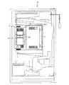
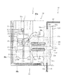
以下、一実施の形態について、添付図面を参照して説明する。図1は、遊技機用基板ボックス封印ユニットの一実施例である封印ユニット1を有する基板被包部材としての基板ボックス(遊技機用基板ボックス)40の配設されたパチンコ機50の背面図である。前記パチンコ機50の正面側には、発射装置により遊技領域へ発射されたパチンコ球を不特定箇所に誘導する複数本のクギや、クギによって誘導されてきたパチンコ球が入賞する複数個の入賞口又は作動口や、特定の遊技状態において比較的多数のパチンコ球を同時に入賞させることができる大入賞口や、各種遊技状態を遊技者に示唆する様々な表示を可能とする表示部等の各種遊技機器が配設されている。図2は、封印ユニット1の配設された基板ボックス40が開封された状態を示す斜視図であり、図3は、封印ユニット1を構成する各部材の分解斜視図であり、図4は、主封印部材21,31により形成された保持部Hに封印金具11が保持されている状態を示した封印ユニット1の部分断面図であり、図5は、基板ボックス40を封印した状態における封印ユニット1の部分断面図であり、図6は、基板ボックス40の分解斜視図であり、図7は、基板ボックス40に貼付する基板管理番号シール61の平面図である。
【0090】
図1および図2を参照して、封印部材としての封印ユニット1が配設される基板ボックス40について説明する。まず、図1に示すように、基板ボックス40は、例えば遊技機の一種であるパチンコ機50の裏側に設けられた入賞球集合カバー51に取り付けられている。基板ボックス40は、パチンコ機50の正面側に露出しないように配設されていればよく、入賞球集合カバー51以外の箇所、例えば、遊技盤裏面、機構盤、前面枠等の枠体、又は専用の支持部材等に取付けられてもよい。基板ボックス40は、パチンコ機50の遊技制御の中枢を担う制御手段としてのCPU、そのCPUの制御下において所定の遊技内容を実現するための制御情報を記憶した制御用ROM、時々刻々変化する遊技状況に関する情報が逐次記憶されるRAM等の電子部品を含む制御回路基板(図示せず)を被包するためのものである。
【0091】
基板ボックス40は、複数のボックス体の組合せによって箱状に構成し得るが、本実施の形態では一対のボックス体からなる例として、第1被包部材としてのボックス本体(ボックスベース)41と、そのボックス本体41に覆設される第2被包部材としてのボックス蓋体(ボックスカバー)42とを備えている場合について説明する(図2参照)。
【0092】
図2に示すように、ボックス本体41は、金属材料からなる箱状体に形成されており、その上方はボックス本体41内に制御回路基板を配設するために開放されている。また、ボックス本体41の側壁41aには、後述する封印ユニット1を構成するユニット部材20が取り付けられている。さらに、ボックス本体41の内側壁には薄板状のガイド板43が設けられており、ボックス本体41にボックス蓋体42を被せる場合、ボックス蓋体42の位置ズレを防止して、容易に被せることができるようになっている。
【0093】
一方、ボックス蓋体42は、ボックス本体41と同様に、金属製の中空箱状体に形成されており、その側壁42aには封印ユニット1を構成するユニット部材30が取り付けられている。ボックス蓋体42の上部壁面には、透明な合成樹脂から構成された覗き窓42dが設けられており、基板ボックス40内の制御回路基板上に設けられた制御用ROM、CPU等の型番号を容易に確認することができるようになっている。このため、制御用ROMを交換してパチンコ機50の遊技内容を変更する不正行為が行われた場合、これを容易に発見することができるようになっている。
【0094】
また、ボックス蓋体42の上面には、基板ボックス40内に配設された制御回路基板を管理するための基板管理番号シール61が貼付される。図7に示すように、未使用の基板管理番号シール61は、当初台紙62に複数枚貼付されており、該基板管理番号シール61が台紙62から1枚ずつ剥がされボックス蓋体42に貼付けられる。この基板番号管理シール61は、特殊シールで構成されており、その表面には、基板管理番号61aと、製造業者コード61bと、枠部61cと、検査履歴61dとが表示されている。基板管理番号61aは、基板ボックス40に被包される制御回路基板のシリアル番号である。また、制御回路基板の製造業者は、枠部61cの色彩と製造業者コード61bとにより特定される。さらに、この基板管理番号シール61は、制御回路基板の検査履歴書でもあり、検査履歴61dには、検査毎に「1」から「3」の欄に検査年月日(開封年月日)、検査者名(開封者名)および検査印等が記録される。
【0095】
尚、基板管理番号シール61を構成する特殊シールは、剥がされると破損してしまったり、痕跡が残る性質を有しているものであって、もしも基板管理番号シール61が不正に剥がされた場合には、かかる不正行為を容易に発見することができるようになっている。
【0096】
さて、図1に示すように、封印ユニット1は基板ボックス40の2箇所にそれぞれ配設されている。ここでは、封印ユニット1は基板ボックス40の相対向する側面に設けられており、特に基板ボックス40が直方体形状である場合には短辺側の側面に設けられる。
【0097】
次に、図3および図4を参照して、前記封印ユニット1を構成する各部材について説明する。図3に示すように、封印ユニット1は、基板ボックス40を封印するための連結保持部材としての封印金具11と、その封印金具11が係止される第1封印部材としてのユニット部材20と、そのユニット部材20に対向してボックス蓋体42に配設され封印金具11が係合される第2封印部材としてのユニット部材30とを備えている。
【0098】
封印金具11は、ユニット部材20,30における各主封印部材21,31を連結するためのものであり、ステンレス鋼材等の金属材料で構成されており、正面視略T字形の略板状体に形成されている。この封印金具11は、主封印部材21に挿設される板部11aと、その板部11aに一体形成されるとともに後述する主封印部材31に係合される頭部11bとを備えている。より詳しくは、板部11aは長方形状の板体となっており、頭部11bは板部11aの短辺一端側に一体にかつ当該短辺よりも幅広に形成されている。そして、頭部11bは板部11aの短辺に沿って延びる筒体となるように巻回されている。
【0099】
板部11aの中間位置は、反頭部11b側を残すようにしてチャンネル状(コ字状)に切欠かれている。この切欠きは横並びに一対施されている。これらの切欠きによって、頭部11b側を自由端、反頭部11b側を固定端とした板片が板部11aに一体形成されている。これら板片の自由端側を互いに相反する方向へ折り曲げることによって、板部11aの表裏側にそれぞれ係止爪11cが形成されている。両係止爪11cの具体的な折り曲げ形状は、特に図4から明らかなように、固定端を基準として板部11aから徐々に遠ざかりながら頭部11b側へ傾斜し、傾斜部分Tの先端から自由端側までは板部11aと略平行となる形状である。
【0100】
両係止爪11cは、封印金具11の板部11aが主封印部材31の挿入孔31bへ挿入され押し込まれた場合、傾斜部分Tを介して板部11a側へと徐々に弾性変形するとともに、封印金具11の先端部が主封印部材21の挿入孔21b内へ挿入される。封印金具11を更に挿し込み続けると、両係止爪11cは、弾性的に復元して主封印部材31の嵌合穴31c内に係止され、主封印部材21の嵌合部21aと主封印部材31の嵌合穴31cとにより形成された保持部Hに収納される(図4参照)。一方、封印金具11の頭部11bは、主封印部材31の係合穴31aの側壁面に当接するとともに、係合穴31a内に保持されている。その結果、封印金具11を主封印部材31内に取り外し不可能な状態で保持することができる。
【0101】
更に、保持部Hに両係止爪11cが保持された封印金具11を押し込むと、両係止爪11cは、板部11a側へ徐々に弾性変形し、主封印部材21の挿入孔21b内へ挿入され、その後、弾性的に復元して主封印部材21の係止孔21c内に係止される。よって、主封印部材21,31は封印金具11により取り外し不可能な状態で連結される(図5参照)。また、封印金具11は、それを取り外そうとした際に両係止爪11cの自由端部が同等に係止孔21c内上側面に当接するように形成されている。
【0102】
板部11aの先端には、略半球状の凸部11dが設けられている。その結果、封印金具11の先端部分の曲げ剛性が強化されるとともに、封印金具11の先端部が凸部11dにより案内され、封印金具11の板部11aの先端部分を後述する主封印部材21,31の挿入孔21b,31bに容易に挿入することができる。また、封印金具11の頭部11bは、主封印部材31の係合穴31aの側壁面に当接するとともに、係合穴31a内に保持されている。その結果、封印金具11を主封印部材31内に取り外し不可能な状態で保持することができる。
【0103】
なお、前記頭部11bの外径は、主封印部材31の係合穴31aの幅と比較して略等しく形成されており、係合穴31aに係合可能となっている。よって、封印金具11の両係止爪11cが係止孔21c内に係止され、その頭部11bが主封印部材31の係合穴31aに係合された場合、主封印部材21,31は封印金具11により取り外し不可能な状態で連結される。その結果、基板ボックス40は開封不可能な状態にて封印される。
【0104】
ユニット部材20は、基板ボックス40のボックス本体41に配設され基板ボックス40を封印するためのものであり、ポリカーボネート樹脂等の耐衝撃性を有する合成樹脂材料で形成されている。このユニット部材20は、封印金具11が挿設される複数の主封印部材21と、ユニット部材20をボックス本体41に取り付けるための取付部材22と、各主封印部材21と取付部材22とを互いに連結するための連結部材23と、各主封印部材21のそれぞれを互いに連結する複数の連結部材24と、各主封印部材21の側面及び底面を覆い隠す被覆部材25(図2参照)とを備えている。尚、各主封印部材21はそれぞれ略同一に構成されているので、以下、同一の部分には同一の番号を付してその説明は省略する。また、図3においては、各ユニット部材20,30の構成をわかりやすく説明するため、便宜上、前記被覆部材25を省略している。
【0105】
図4に示すように、主封印部材21は略円柱状に形成されており、その一部には連結部材23が固着され取付部材22に連結されている。この主封印部材21は、略等間隔で取付部材22に計4個連結されており、各主封印部材21の上端部分には、嵌合部21aが設けられている。嵌合部21aは、略円柱状に形成されており、その上側部分の外径は下側部分の外径と比較して小さくなるようにテーパ加工が施されている。よって、嵌合部21aを後述する主封印部材31の嵌合穴31cに容易に挿入して嵌合させることができる。嵌合部21aの上面には、長穴状の挿入孔21bが凹設されており、封印金具11の板部11aが挿入可能に形成されている。この挿入孔21bの開口部分には面取り部Cが形成されており、この面取り部Cにより封印金具11の板部11aおよび両係止爪11cが容易に挿入される。
【0106】
嵌合部21aの壁面の一部から対向する壁面に向かって貫通するように、略矩形状の係止孔21cが設けられており(図3参照)、この係止孔21cは挿入孔21bと連通している(図4参照)。よって、挿入孔21bから封印金具11を挿入すると、封印金具11の両係止爪11cが主封印部材21の係止孔21cにより係止され、封印金具11の抜き取り行為が防止される。また、嵌合部21aの外周には、嵌合溝21dが凹設されており、主封印部材31のスカート部31dが嵌合可能となっている。この嵌合溝21dの開口部分の断面積は底部分の断面積と比較して大きくなるようにテーパ加工が施されており、スカート部31dを容易に嵌合させることができる。また、嵌合溝21dにスカート部31dを嵌合させることにより、主封印部材21,31の位置ズレが防止され、主封印部材21と主封印部材31とを確実に合致させることができる。
【0107】
取付部材22は、封印ユニット1のユニット部材20をボックス本体41に取り付けるためのものであり、対向して配設された一対の板状体22a,22bと、その一対の板状体22a,22bを互いに連結する複数の連結部材22cと、板状体22bに配設された補強部材22dとを備えている。各板状体22a,22bは複数の連結部材22cにより連結されており、この複数の連結部材22cは計4箇所に配設されている。この各連結部材22cは、板状体22aの長手方向に略等間隔で配設された複数の連結部材23に対応して配設されている。
【0108】
よって、取付部材22のうち、連結部材23が固着されている部分の厚みは大きく形成され、その強度は強化されている。従って、基板ボックス40の内部を確認するために連結部材23を切断して主封印部材21を除去する場合、取付部材22の板状体22a,22bに損傷を与えることなく連結部材23を切断することができるようになっている。また、取付部材22における一対の板状体22a,22bの間には所定幅の間隙W1が形成されており、この一対の板状体22a,22bの間に形成された間隙W1は、ボックス本体41の側壁41aの板厚より大きく形成されている。
【0109】
図6に示すように、ボックス本体41の側壁41aには、取付部材22の各連結部材22cに対応した略矩形状の係合溝41bが略等間隔で計4箇所に形成されている。この各係合溝41bには、各連結部材22cをそれぞれ係合させることができる。かかる係合により、ボックス本体41の側壁41aはユニット部材20の取付部材22における板状体22a,22bの間に挟み込まれ、図2に示すように、ユニット部材20がボックス本体41に取り付けられる。その結果、板状体22a,22bの間に挟み込まれた側壁41a部分の剛性を向上させることができるとともに、ボックス本体41の側壁41aに取り付けられたユニット部材20を外れ難くすることができる。
【0110】
また、取付部材22の長手方向の両端部分には一対の取付孔22eが板状体22a,22bのそれぞれを貫通して穿設されている(図3および図4参照)。ボックス本体41の側壁41aには、これら一対の取付孔22eに対応して、一対の係合穴41cが穿設されている(図6参照)。よって、ユニット部材20の板状体22a,22bの間にボックス本体41の側壁41aを挟み込みつつ、ユニット部材20の取付部材22をボックス本体41の側壁41aに「かしめ」またはネジ止めにより固定することができる(図2および図3参照)。
【0111】
図4に示すように、取付部材22の板状体22bには、略矩形状の係止穴22fが穿設されている。この係止穴22fには、ボックス本体41の側壁41a内側面に突設された係止爪41eが係止されており、ユニット部材20をボックス本体41の側壁41aに「仮止め」することができる。よって、かかる「仮止め」によって前記「かしめ」またはネジ止めによるユニット部材20の固定作業を容易に行うことができる。
【0112】
補強部材22dは、封印ユニット1が配設された基板ボックス40の強度を補強するためのものであり、取付部材22の板状体22bにおける上部側面に一体に形成されている(図4の右部参照)。この補強部材22dは、後述するユニット部材30に形成された嵌合穴32dに嵌合可能となっており(図3参照)、かかる嵌合穴32dに嵌合することにより、ユニット部材20,30を互いに位置決めしつつ、封印ユニット1の配設された基板ボックス40の強度を補強することができるようになっている。
【0113】
図3に示すように、連結部材23は、各主封印部材21と取付部材22とをそれぞれ連結するためのものである。この連結部材23は、取付部材22の板状体22aの一側面に略等間隔で計4個配設されており、各連結部材23には主封印部材21がそれぞれ固着されている。よって、計4個の各主封印部材21が略等間隔で隣接して取付部材22と連結され、ユニット部材20が一体に形成されている。また、各主封印部材21は、連結部材24により互いに連結されて、一体に形成されている。また、主封印部材21と取付部材22との間には、連結部材23を切断するために、ニッパ等の工具の刃先が入り込むための間隔が形成される。すなわち、基板ボックス40の内部を確認する際には、ニッパ等の工具が用いられることにより連結部材23が容易に切断され、これにより主封印部材21が除去されるようになっている。
【0114】
連結部材24は、隣り合う各主封印部材21を連結して、ユニット部材20の強度を補強するためのものであり、略薄板状に形成されている。この各連結部材24の一方には、切り欠き24aが設けられており、かかる部分の剛性を低下させてある。よって、ニッパ等の工具を用いて1つの連結部材24を切断する場合、切り欠き24a部分を切断することにより、容易に連結部材24を切断することができる。また、切り欠き24aは、連結部材24のうち、先に使用される主封印部材21側(図3では右側)の端部分に設けられているので、連結部材24を切断する場合、未使用の主封印部材21の損傷を防止することができるようになっている。
【0115】
被覆部材25は、主封印部材21,31の外部より孔が開けられ、封印金具11が抜き取られたりするのを防ぎ、もって不正に基盤ボックス40が開封されるのを防止するために設けられたものである。被覆部材25は、4つ並んだ主封印部材21,31の両端部側面を被覆するように形成された側面被覆部25aと、各主封印部材21の底面部を被覆するように形成された底面被覆部25bと、各主封印部材21,31の取付部材22,32とは反対側にあたる各主封印部材21,31前面部を被覆するように形成された前面被覆部25cとで構成されている。側面被覆部25a、底面被覆部25bおよび前面被覆部25cはそれぞれ略板状体であるとともに、各板状体とも略平行に配設された複数枚、例えば3枚の板状体で構成されている。また、平行状態にある各板状体の間には所定の隙間が形成されている。なお、前記各被覆部25a〜25cはそれぞれポリカーボネート樹脂等の耐衝撃性を有する合成樹脂材料で形成されている。側面被覆部25aは、その板状面が前記両端部側面を向くように、取付部材22の板状体22aに固着されている。底面被覆部25bは、その板状面が各主封印部材21の底面部を向くように、取付部材22の板状体22aに固着されている。さらに、側面被覆部25aと底面被覆部25bとは互いに交わる部分で固着されている。また、前面被覆部25cは、その板状面が各主封印部材21,31前面部を向くように、側面被覆部25aおよび底面被覆部25bにそれぞれ固着されている。側面被覆部25aおよび前面被覆部25cの上端部は前記主封印部材31の上端部と同等の高さに形成されている。なお、各主封印部材21,31上面部は被覆部材25によって被覆されていない。つまり、被覆部材25は、各主封印部材21,31の上面部が被覆されないように図の上方に開口した状態で形成されている。
【0116】
さらに、ユニット部材30は、封印金具11とユニット部材20とを介して、基板ボックス40を封印するためのものである。ユニット部材30は、ポリカーボネート樹脂等の耐衝撃性を有する合成樹脂材料で形成されており、基板ボックス40のボックス蓋体42の側壁42aに取り付けられている。このユニット部材30は、封印金具11が係合される主封印部材31と、ユニット部材30をボックス蓋体42に取り付けるための取付部材32と、各主封印部材31と取付部材32とを互いに連結するための連結部材33と、各主封印部材31のそれぞれを互いに連結する複数の連結部材34とを備えている。尚、各主封印部材31はそれぞれ略同一に構成されているので、以下、同一の部分には同一の番号を付してその説明は省略する。
【0117】
図3に示すように、主封印部材31は、略円柱状に形成されており、その一部には連結部材33が固着され取付部材32に連結されている。この主封印部材31は、略等間隔を隔てて計4個連結されており、各主封印部材31は前述したユニット部材20の各主封印部材21と対向する位置に設けられている(図2参照)。また、各主封印部材31は、封印金具11の頭部11bの係合される係合穴31aと、その係合穴31aに連通して穿設された挿入孔31bと、さらにその挿入孔31bに連通して穿設された嵌合穴31cと、その嵌合穴31cの下方に設けられたスカート部31dとを備えている。
【0118】
前記主封印部材31の上面に形成された係合穴31aは、封印金具11の頭部11bが嵌合可能になっている。また、その下方に設けられた挿入孔31bは、その幅が封印金具11の頭部11bの外径と比較して小さく形成されており、該頭部11bは挿入孔31bを通り抜けることができず、係合穴31a内に確実に係合される。さらに、挿入孔31bの下方に連通して設けられた嵌合穴31cには、前記主封印部材21の嵌合部21aが嵌合可能になっており、この嵌合穴31cにはテーパ加工が施されている。これにより、主封印部材21の嵌合部21aが容易に挿入されて嵌合させることができるようになっている。
【0119】
また、嵌合穴31cの上壁面と主封印部材21の嵌合部21aの上端面との間には、所定高さを有する保持部Hが形成されており、封印金具11の両係止爪11cが嵌合部21aの上端面により支持され保持されている。また、封印金具11の両係止爪11cが保持部Hにて保持されると、封印金具11の頭部11bは、係合穴31a内に埋め込まれ、主封印部材31の上面から突出することがない。よって、頭部11bを掴んで封印金具11を抜き取る不正行為や頭部11bが何かに引っ掛かり封印金具11が抜け落ちてしまうことを防止することができる。その結果、予備用(未使用)の封印金具11は、主封印部材21と主封印部材31とを連結することなく、かつ、主封印部材31内において抜き取り不可能な状態で保持することができるようになっている。
【0120】
主封印部材31の下端面であって、嵌合穴31cの縁部分に周設されたスカート部31dは、主封印部材21の嵌合溝21dに嵌合可能に形成されており、その外周壁にはテーパが施されている。よって、スカート部31dを嵌合溝21dへ容易に嵌合させることができる。
【0121】
取付部材32は、封印ユニット1のユニット部材30をボックス蓋体42に取り付けるためのものであり、対向して配設された一対の板状体32a,32bと、その一対の板状体32a,32bを互いに連結する複数の連結部材32cと、板状体32bに配設された嵌合穴32dとを備えている。各板状体32a,32bは複数の連結部材32cにより連結されており、この複数の連結部材32cは計4箇所に配設されている。各連結部材32cは、板状体32aの長手方向に略等間隔を隔てて配設された連結部材33に対応して配設されている。
【0122】
よって、取付部材32のうち、連結部材33が固着されている部分の厚みは大きく形成され、その強度が強化されている。従って、連結部材33を切断して主封印部材31を除去する場合、取付部材32の板状体32aに損傷を与えることがない。また、取付部材32における一対の板状体32a,32bの間には所定幅の間隙W2が形成されており、この一対の板状体32a,32bの間に形成された間隙W2は、ボックス蓋体42の側壁42aの板厚より大きく形成されている。
【0123】
図6に示すように、ボックス蓋体42の側壁42aには、取付部材32の各連結部材32cに対応した略矩形状の係合溝42bが略等間隔で計4箇所に形成されており、この各係合溝42bは、ボックス本体41に形成された各係合溝41bに対向して側壁42aに形成されている。この係合溝42bには、取付部材32の各連結部材32cをそれぞれ係合させることができる。各係合溝42bに各連結部材32cを係合すると、ボックス蓋体42の側壁42aは、ユニット部材30の取付部材32における板状体32a,32bの間に挟み込まれ、図2に示すように、ユニット部材30がボックス蓋体42に取り付けられる。その結果、板状体32a,32bの間に挟み込まれた側壁42a部分の剛性を向上させることができるとともに、ボックス蓋体42の側壁42aに取り付けられたユニット部材30を外れ難くすることができる。
【0124】
また、取付部材32の長手方向の両端部分には、一対の取付孔32eが板状体32a,32bのそれぞれを貫通して穿設されている(図3および図4参照)。ボックス蓋体42の側壁42aには、前記取付孔32eに対応して、一対の係合穴42cが穿設されている(図6参照)。よって、ユニット部材30の板状体32a,32bの間にボックス蓋体42の側壁42aを挟み込みつつ、取付部材32をボックス蓋体42の側壁42aに「かしめ」またはネジ止めにより固定することができる(図2および図3参照)。
【0125】
図4に示すように、取付部材32の板状体32bには、略矩形状の係止穴32fが穿設されている。この係止穴32fには、ボックス蓋体42の側壁42a内側面に突設された係止爪42eが係止されており、ユニット部材30をボックス蓋体42の側壁42aに「仮止め」することができる。かかる「仮止め」によって、前述した「かしめ」またはネジ止めによるユニット部材30の固定作業を容易に行うことができる。
【0126】
尚、ボックス本体41とユニット20およびボックス蓋体42とユニット30は、それぞれ合成樹脂材料を使用して一体成形しても良い。
【0127】
嵌合穴32dは、ユニット部材20の補強部材22dを嵌合しつつ、封印ユニット1が配設された基板ボックス40の強度を補強するためのものである。この嵌合穴32dは、ユニット部材20の補強部材22dが嵌合可能に穿設された上面視略矩形状の貫通穴である(図3参照)。この嵌合穴32dに補強部材22dを嵌合することにより、封印ユニット1、及び、その封印ユニット1が配設された基板ボックス40の剛性を大きくすることができる。
【0128】
図3に示すように、各主封印部材31と取付部材32とを連結する連結部材33は、取付部材32の板状体32aの一側面に略等間隔を隔てて計4個配設されている。よって、計4個の各主封印部材31が連結部材33を介して略等間隔で取付部材32に連結されることにより、ユニット部材30が一体に形成されている。また、主封印部材31と取付部材32との間には、ニッパ等の工具の刃先が入り込むための間隔が形成される。すなわち、基板ボックス40の内部を確認する際には、ニッパ等の工具が用いられることにより連結部材33が容易に切断され、これにより主封印部材31が除去されるようになっている。
【0129】
また、連結部材34は、隣り合う各主封印部材31を連結して、ユニット部材30の強度を補強するためのものであり、略薄板状に形成されている。各連結部材34は、各主封印部材31の外周面のうち連結部材33の固着側の反対部分に固着されており、各主封印部材31のそれぞれを互いに連結してユニット部材30の強度を補強している。この各連結部材34の一側部分には、切り欠き34aが設けられており、かかる部分の剛性を低下させてある。よって、ニッパ等の工具を用いて連結部材34を切断する場合、切り欠き34aが設けられた部分を切断することにより、容易に連結部材34を切断することができる。また、切り欠き34aは、連結部材34のうち、先に使用される主封印部材31側(図の右側)の端部に設けられているので、連結部材34を切断する場合、未使用の主封印部材31の損傷を防止することができる。
【0130】
各連結部材34の上面には、「1」から「4」までの番号表示Kがそれぞれ表示されている。この各番号表示Kは、ユニット部材30の成形と同時に成形されており、各一対の主封印部材21,31が封印される順番を表している。よって、各主封印部材21とそれに対向する各主封印部材31とを「1」から「4」の各番号表示Kの順に封印金具11を用いて封印するとともに、「1」から「4」の番号表示Kの順に封印された主封印部材21又は31に対応する連結部材23,24または連結部材33,34をニッパ等の工具を用いて切断することによって主封印部材21又は31を除去することができるようになっている。
【0131】
尚、この各番号表示Kを付す方法としては、「1」から「4」の数字を印刷した合成樹脂等のシート等を各主封印部材21に貼付等したりしても良い。
【0132】
次に、上述した基板ボックス40に取り付けられた封印ユニット1の使用方法について説明する。まず、ユニット部材20の各連結部材22cをボックス本体41の各係合溝41bに対応させて係合し、取付部材22の一対の板状体22a,22bの間にボックス本体41の側壁41aを挟み込むようにして、取付部材22を側壁41aに填め込む。その後、取付部材22の板状体22bに設けられた係止穴22fがボックス本体41の係止爪41eにより係止されるまで填め込み、ユニット部材20をボックス本体41に「仮止め」して、取付孔22eおよび係合穴41cを「かしめ」またはネジ止めにより固定する。
【0133】
また、同様に、ボックス蓋体42の各係合溝42bにユニット部材30の各連結部材32cを対応させて係合し、取付部材32の一対の板状体32a,32bの間にボックス蓋体42の側壁42aを挟み込むようにして、取付部材32を側壁42aに填め込む。その後、取付部材32の板状体32bに設けられた係止穴32fがボックス蓋体42の係止爪42eにより係止されるまで填め込み、ユニット部材30をボックス蓋体42に「仮止め」して、取付孔32eおよび係合穴42cを「かしめ」またはネジ止めにより固定する。
【0134】
このようにして、ユニット部材20,30をそれぞれ2個ずつボックス本体41およびボックス蓋体42に固定する(図1参照)。
【0135】
その後、ボックス本体41内に制御回路基板を配設して固定した後、ユニット部材20,30の各主封印部材21,31を対向させて、ボックス本体41にボックス蓋体42を被せ、各主封印部材21の嵌合部21aを各主封印部材31の嵌合穴31cに嵌合するとともに、各主封印部材31のスカート部31dを各主封印部材21の嵌合溝21dに嵌合する。そして、計4個の各主封印部材31の係合穴31aおよび挿入孔31b内に封印金具11をそれぞれ挿入して、その頭部11bを押下し封印金具11を主封印部材31内に押し込む。
【0136】
封印金具11が押し込まれると、封印金具11の両係止爪11cは、傾斜部分Tを介して板部11a側へ徐々に弾性変形する。更に、封印金具11を挿入し続けると、両係止爪11cが弾性的に復元し、その両係止爪11cは、嵌合穴31c内に係止されるとともに保持部Hに保持される。よって、各封印金具11を主封印部材31内に抜き取り不可能な状態で保持することができるとともに、封印金具11の紛失を防止することができる(図4参照)。
【0137】
各主封印部材31内に各封印金具11を保持した後、各封印ユニット1の主封印部材31のうち、「1」の番号表示Kの付された連結部材24の左端部が固着されているもの(図2中右側)に挿入された封印金具11の頭部11bを押下して、その封印金具11を更に押し込む。封印金具11が押し込まれると、封印金具11の両係止爪11cは、傾斜部分Tおよび挿入孔21bの面取り部Cを介して板部11a側へ徐々に弾性変形する。封印金具11を挿入し続けると、両係止爪11cが弾性的に復元して、両係止爪11cが主封印部材21の係止孔21c内に係止され、封印金具11が主封印部材21内にて抜き取り不可能な状態で保持される。
【0138】
その結果、封印金具11は、主封印部材21内から抜き取り不可能となり、更に、封印金具11の頭部11bは、主封印部材31の係合穴31aに係合されているので、基板ボックス40のボックス本体41とボックス蓋体42とが開封不可能に連結され、基板ボックス40を確実に封印することができる(図5参照)。
【0139】
また、主封印部材21,31の側面又は底面から孔を開けて封印金具11の両係止爪11cを弾性変形させ、封印金具11を抜き取る等の不正行為を行おうとした場合、被覆部材25が主封印部材21,31の周囲に設けられているため、被覆部材25の表面上から孔を開けなければならなくなり、孔を開けた痕跡がより発見し易くなる。又、封印金具11までの間に複数の壁が存在することやその壁によって被覆部材25の表面上から封印金具11まで距離が長くなることで、棒状のものを封印金具11の位置まで差し込んで、両係止爪11cを弾性変形させるには、その力を加えるための支点が定まりにくく、上記不正行為を行い難くなる。
【0140】
さらに、本実施の形態における封印金具11には、その両側面に1個ずつ両係止爪11cが形成されている。このため、封印金具11を抜き取るには、両側面の両係止爪11cを同時に押さえつけなければない。しかし、上記被覆部材25の表面上から両係止爪11cを同時に押さえつけるのは、非常に困難となる。その結果、上記不正行為をさらに行い難くなる。
【0141】
よって、基板ボックス40に被包された制御回路基板上の制御用ROM等を不適法に取り外して、パチンコ機50の遊技内容を変更する不正行為を防止することができる。また、主封印部材21,31自体を破壊、切断等すれば基板ボックス40を開封することができるが、その場合には、基板ボックス40が開封された痕跡を確実に残すことができる。即ち、不正行為が行われたか否かを即座に発見することができる。
【0142】
さて、上述したように、係止爪11cを有する封印金具11により、ボックス本体41とボックス蓋体42とが開封不可能に構成されていること、及び、主封印部材21,31の周囲に被覆部材25が設けられていること等により、不正行為を行うことが困難となるよう構成されているが、連結部材23,33をレーザカッタ等により巧妙に切断して、基板ボックス40を開封するといった不正が行われることも考えられる。この場合、従来では不正な基板に取り替えたり、制御用ROM等を不適法に取り替えたりした後で、切断面を再度巧妙に接合することで、不正が行われた事実を確認しにくくすることも考えられる。
【0143】
これに対し、本実施の形態では、前記各連結部材23,33内にはカプセル部材71,72が埋設されている。カプセル部材71,72は、薄肉のガラス製の壁部と、該壁部内に封入され、状態変化手段、収容物、物質を構成する着色塗料とによって構成されている。着色塗料としては、ニトロセルロースラッカー等のセルロース系塗料、アルキド樹脂エナメル、アミノアルキド樹脂エナメル、熱硬化性アクリル樹脂エナメル、アクリルラッカー、エポキシ樹脂塗料、フェノール樹脂塗料、塩化ビニル樹脂塗料、塩化ゴム塗料、不飽和ポリエステル樹脂ワニス、ポリウレタン樹脂塗料等の合成樹脂塗料、酢酸ビニルラテックスペイント等の水性塗料等が挙げられる。中でも、速乾性の有機溶媒を有する合成樹脂塗料が好適に用いられる。なお、カプセル部材71,72は、それぞれユニット部材20,30を成型する際にインサート成形によって埋設されている。さらに、カプセル部材71,72は、連結部材23,33のみならず、主封印部材21,31及び取付部材22,32にまで及んでいる。このため、連結部材23,33と、主封印部材21,31又は取付部材22,32との境界部位が巧妙に破断等された場合であってもカプセル部材71,72の壁部が破られ、塗料が漏出するようになっている。
【0144】
さて、基板ボックス40を不正に開封する場合には、少なくとも、連結部材33および「2」の番号表示Kが付された連結部材34をニッパ、レーザカッタ等により切断するか、又は、連結部材23および連結部材24をニッパ、レーザーカッタ等により切断する必要がある。即ち、少なくとも連結部材23,24または連結部材33,34をそれぞれ切断しなければ、基板ボックス40を開封することができない。よって、不正行為を行った者が、基板ボックス40を開封して制御回路基板に不正改造等の不正行為を行った後、その不正行為を隠蔽する場合には、連結部材23,24または連結部材33,34の各切断部分のそれぞれに接着剤等を塗布し、かかる複数の切断部分をそれぞれ巧妙に再接合する必要がある。また、複数の切断部分を再接合して、切断の痕跡を隠蔽することは容易ではない。
【0145】
さらに、本実施の形態では、連結部材23,33等が切断された場合には、内部に埋設されているカプセル部材71,72の壁部が破られ、着色塗料が漏出するとともに、それが痕跡となって残存する。このため、不正行為を行ったことが一目瞭然となり、不正行為の隠蔽を確実に行うことができない。従って、不正行為を早期にかつ容易に発見することができるとともに、ひいては間接的にかかる不正行為を抑制することができる。
【0146】
ここで、封印状態にある基板ボックス40を正規の手法で開封して制御回路基板上の制御用ROMを取り外して検査する方法について説明する。上記のように、封印金具11の頭部11bは主封印部材31の係合穴31aに係合され、封印金具11の両係止爪11cは主封印部材21の係止孔21c内に抜き取り不可能な状態で保持されているので、基板ボックス40内の制御回路基板を適法に検査する場合、単純に封印金具11を外して、基板ボックス40を開封することはできない。すなわち、封印金具11により封印されている主封印部材21,31と取付部材22,32とを連結している連結部材23,33を、ニッパ等の工具を用いて切断するとともに、封印されている主封印部材21,31と他の主封印部材21,31とを連結する連結部材24,34の切り欠き24a,34aの部分を切断する。
【0147】
このようにして、連結部材23,24,33,34を切断することにより、基板ボックス40の封印が解除され、ボックス本体41からボックス蓋体42を外すことができる。そして、制御用ROM等の検査終了後、基板管理番号シール61の検査履歴61dに所定の事項を記載して、ボックス本体41にボックス蓋体42を被せて、未使用の一対の主封印部材21,31に保持されている封印金具11を押し込むことにより、かかる主封印部材21,31を連結して、基板ボックス40を再度封印する。もちろん、上記連結部材23,33の切断に際しては、カプセル部材71,72の壁部が破られ、着色塗料が漏出するが、この場合には正規の手法に基づく開封であるため、そのことを図7の基板管理番号シール61等に記録したり、別の台帳等に記録したり、或いは記憶手段等に記憶させておけば不正行為によるものではないことを明確にしておくことができる。
【0148】
尚、本実施の形態では、各封印ユニット1に、主封印部材21,31が各4個ずつ計4組設けられているので、最大3回まで基板ボックス40の封印を解除して開封することができる。また、止むを得ず全ての主封印部材21,31を切断して排除した場合には、ユニット部材20,30をボックス本体41およびボックス蓋体42に固定する「かしめ」またはねじ止めを取り外し、新たなに封印ユニット1のユニット部材20,30をボックス本体41およびボックス蓋体42に取り付ければよい。
【0149】
また、各4個ずつの主封印部材21,31に対応する各連結部材23,33に上記カプセル部材71,72が埋設されるが、この場合、各連結部23,33毎に着色塗料の色彩が相違するよう構成してもよい。このように構成することで、連結部材23,33の切断が行われて塗料が漏出する度に異なる外観(色調)を呈するため、何回目の封印解除が行われたのかを容易に把握することが可能となる。また、いずれの主封印部材21,31に関して解除操作が行われたのかを把握できる。このため、一旦正規の手法に基づいて基板ボックス40が開封された場合であっても、別の主封印部材が操作されたことを容易かつ確実に把握することが可能となる。
【0150】
尚、上述した実施の形態の記載内容に限定されることなく、例えば次のように実施してもよい。
【0151】
(a)上記実施の形態では、カプセル部材71,72は、連結部材23,33のみならず、主封印部材21,31及び取付部材22,32にまで及ぶ構成としたが、連結部材23,33のみに設ける構成としてもよいし、破断等により塗料の漏出が可能な構成であれば、主封印部材21,31、或いは取付部材22,32のみに設けることとしてもよい。
【0152】
(b)図8に示すように、ユニット部材20,30の相互の当接面(主として連結部23,33の当接面)に、上端側、下端側がそれぞれ開口する収容部73,74を形成しておいて、両ユニット部材20,30を当接させる際に該収容部73,74内にカプセル部材75を収容させることとしてもよい。このように構成することで、カプセル部材75を封入状態に維持することができる。このため、上記実施の形態のように別途ユニット部材20,30の成形時にインサート成形等を行ったりする必要がなくなり、設置作業を著しく容易に行うことができる。
【0153】
(c)上記実施の形態では、着色塗料が壁部にて封入されたカプセル部材71,72を設けることとしたが、必ずしもカプセル状としなくてもよい。例えば、塗料等の液状物を連結部材23,33等に直接封入する構成としてもよい。このような構成としても、連結部材23,33等が切断された場合に、塗料等の漏出が起こり、不正行為の発見を行うことが可能となる。
【0154】
(d)着色塗料以外にも透明、半透明の塗料を用いてもよい。このように透明性を付与することで、不正行為者が気付きにくい場合があり、証拠として塗料等を残存させやすくなる。その結果、より確実に不正行為を発見することが可能となる。この場合の塗料としては、蛍光塗料や、所定の光線(例えば紫外線や赤外線)を当てることにより発色する透明塗料等を例示することができる。
【0155】
(e)塗料以外にも、例えば、着色料を含んだ水溶液、染料、接着剤といった他の液状物を用いてもよい。もちろん、所定の粘性を有していたり、固形物を分散状態で含む液状物であってもよい。
【0156】
(f)状態変化手段、収容物としては、液状物に限られず、固体物であってもよい。固体物としては、紛状物や粒状物、或いは、完封状態が解除されたときに体積変化を起こすようなもの等、外観上、当初の封止状態とは相違する状態となることが明らかとなるようなものが好ましい。なお、粉体物の例として、粉体塗料を挙げることができ、その具体例としてエポキシ系、アクリル系、ポリエステル系の粉体塗料が挙げられる。
【0157】
(g)カプセル部材71,72の壁部を構成する素材は、ガラス以外のプラスチック、ゴム、金属等であってもよい。
【0158】
(h)上記実施の形態では特に言及していないが、カプセル部材71,72や塗料等が外部から視認出来る構成であってもよいし、視認できない構成であってもよい。外部から視認できない構成とした場合には、不正行為者はカプセル部材71,72が設けられていることに当初は気づきにくく、塗料等が漏出した場合に初めて気付く場合が生じ、場合によっては、不正を未遂で終わらせることも可能となる。
【0159】
(i)上記実施の形態における被覆部材25を省略する構成としてもよい。また、上記被覆手段25をもって着色塗料が漏出した場合の流出防止手段としてもよい。すなわち、正規に或いは不正に連結部材23,33を切断した場合には、着色塗料が漏出するのだが、被覆部材25の存在により塗料が外部に滴下したりするのを防止することができる。この場合に、被覆部材25に別途返し部を主封印部材21,31の(図2の)上面部分に設けることによって、塗料受け部を構成することとしてもよい。また、スポンジ、紙、受け皿等の流出防止手段を別途設けることにより、塗料が流下したり滴下したりするのを防止するようにしてもよい。同様に、基板側に塗料が流下したり滴下したりするのを防止するスポンジ、紙、受け皿等の流出防止手段を設けてもよい。この場合、図1の上部に配設される封印ユニット1に対応して流出防止手段が設けられる。
【0160】
(j)上記実施の形態では、主として遊技機の主基板を封印する遊技機用基板ボックス封印ユニットを説明しているが、前記遊技機用基板ボックス封印ユニットを遊技機に存在する各種基板を収納する基板ボックスにそれぞれ設けることとしてもよい。例えば、遊技機の各種回路の電源を制御する電源基板、パチンコ球の払い出しを制御する払出制御基板、パチンコ球の発射を制御する発射制御基板、図柄等を表示する可変表示装置を制御する表示制御基板、音声を制御する音声制御基板、ランプの点灯等を制御するランプ制御基板等を封印する基板ボックスに封印ユニットを設けてもよい。特に前記払出制御基板のように、不正行為を行われやすい基板を収納した遊技機用基板ボックスに封印ユニットを設ければ、収納された制御基板からROMを取り外して交換したり基板を交換したりすることにより、払い出されるパチンコ球数を変更するといった不正行為を防止することができる。
【0161】
(k)また、本実施の形態における遊技機用基板ボックス封印ユニットとしての封印ユニット1を構成する封印部材21,31は、基板ボックス40を構成するボックス本体41及びボックス蓋体42とはそれぞれ別体で構成されていたが、これを一体として遊技機用基板ボックス封印ユニットとしてもよい。
【0162】
(l)上記実施の形態における封印金具11の両係止爪11cは、板部11a左右側面上に上下方向の中心軸を挟んで略対称となるように形成されているが、これに限らず、複数の係止爪11cを板部11aの側面上の上下方向にずらして配設する構成としてもよい。このような構成にすれば、主封印部材21,31の連結を解除するにあたり、複数の係止爪11cを何度も押さえつけなければならないため、不正行為を行い係止爪11cの係止解除を行うのは困難になる。
【0163】
また、係止爪11cを板部11aの片側側面上に1つだけ設けて、これを基板ボックス40に対向するよう挿入することとしてもよい。このようにすれば、係止爪11cが1つだけでも、係止爪11cに向かって孔を開け、係止爪11cを押さえ付けることは困難となる。結果として、主封印部材21,31の連結状態を解除することは容易にはできなくなり、不正行為を防止することができる。
【0164】
さらに、本実施の形態において、封印金具11は略板状体の形状のものを使用したが、これに限らず、略棒形状等の封印金具を使用することとしてもよい。又は、封印金具は金具でなくとも、例えば樹脂等の主封印部材21,31を連結できるものであれば、何でもよい。
【0165】
(m)上記実施の形態では、主封印部材21,31を連結し基板ボックス40を封印するための連結保持部材として封印金具11を使用した。しかし、かかる部材は、これに限られるものではなく、例えば上記従来の技術で説明したような封印ねじ等を使用してもよい。
【0166】
(n)上記実施の形態とは異なるタイプのパチンコ機等として実施してもよい。例えば、一度大当たりすると、それを含めて複数回(例えば2回、3回)大当たり状態が発生するまで、大当たり期待値が高められるようなパチンコ機(通称、2回権利物、3回権利物と称される)として実施してもよい。また、大当り図柄が表示された後に所定の領域に遊技球を入賞させることを必要条件として特別遊技状態となるパチンコ機として実施してもよい。また、パチンコ機以外にも、アレパチ、雀球、スロットマシン、いわゆるパチンコ機とスロットマシンとが融合した遊技機等の各種遊技機として実施することも可能である。なお、スロットマシンは、例えばコインを投入して図柄有効ラインを決定させた状態で操作レバーを操作することにより図柄が変動され、ストップボタンを操作することにより図柄が停止されて確定される周知のものである。
【0167】
また、パチンコ機とスロットマシンとが融合した遊技機の具体例としては、複数の図柄からなる図柄列を変動表示した後に図柄を確定表示する可変表示手段を備えており、遊技球打出用のハンドルを備えていないものが挙げられる。この場合、所定の操作(ボタン操作)に基づく、所定量の遊技球の投入の後、例えば操作レバーの操作に起因して図柄の変動が開始され、例えばストップボタンの操作に起因して或いは所定時間経過することにより図柄の変動が停止され、その停止時の確定図柄がいわゆる大当たり図柄であることを必要条件として遊技者に有利な大当たり状態が発生させられ、遊技者には、下部の受皿に多量の遊技球が払い出されるものである。
【0168】
(o)封印ユニット1に加えて、又は、代えてボックス本体若しくはボックス蓋体、又は、ボックス本体及びボックス蓋体双方に着色塗料等の物質を設けることとしてもよい。
【0169】
例えば、図9に示すように、ボックス本体81に対しボックス蓋体82が被せられる構成となっている場合において、ボックス本体81の側壁部83には収容部84が形成されているとともに、ボックス蓋体82の側壁部85にも収容部86が形成されている。そして、例えば収容部84に、着色塗料の封入されたカプセル部材87を収容する。このとき、収容部84及びカプセル部材87間には接着剤を介在させるのが望ましい。次に、収容部86に前記カプセル部材87の突出部分が収容されるようボックス本体81に対しボックス蓋体82を被せる(このとき収容部86及びカプセル部材87間にも接着剤を介在させるのが望ましい)。その後、ボックス本体81及びボックス蓋体82を接合固定する。このように構成することで、不正にボックス蓋体82を取り外そうとした場合に、カプセル部材87が破断して着色塗料が漏出し、痕跡を残させることが可能となる。また、同図に示すように側壁部83に延長壁部(流出防止手段)88を設けておけば、塗料がボックス本体81内部に流入してくるのを抑制することができる。なお、この場合においても、上記実施の形態のような封印ユニットを設けない構成としても何ら差し支えない。
【0170】
また、図9では、収容部84,86を共に側壁部83,85に設けることとしたが、ボックス本体又はボックス蓋体のいわゆる本体部分に設けることとしてもよい。例えば図10に示すように、ボックス本体91に対しボックス蓋体94が被せられる構成となっている場合において、ボックス本体91の側壁部92には収容部93が形成されているとともに、ボックス蓋体94の本体部分たる天板部に収容部95が形成されている。そして、例えば収容部93に、着色塗料の封入されたカプセル部材87を収容する。このとき、収容部93及びカプセル部材87間には接着剤を介在させるのが望ましい。次に、収容部95に前記カプセル部材87の突出部分が収容されるようボックス本体91に対しボックス蓋体94を被せる(このとき収容部95及びカプセル部材87間にも接着剤を介在させるのが望ましい)。その後、ボックス本体91及びボックス蓋体94を接合固定する。このように構成しても、上記と同様の作用効果が奏される。
【0171】
【発明の効果】
本発明の遊技機によれば、不正行為を抑制することができる。
【図面の簡単な説明】
【図1】一実施の形態における封印ユニットを有する基板ボックスの配設されたパチンコ機の背面図である。
【図2】封印ユニットが配設された基板ボックスが開封された状態を示す斜視図である。
【図3】封印ユニットを構成する各部材の分解斜視図である。
【図4】保持部に封印金具が保持されている状態における封印ユニットの部分断面図である。
【図5】基板ボックスを封印した状態における封印ユニットの部分断面図である。
【図6】基板ボックスの分解斜視図である。
【図7】基板管理番号シールの平面図である。
【図8】別の実施の形態において基板ボックスを封印した状態における封印ユニットの部分断面図である。
【図9】別の実施の形態における基板ボックス等を示す部分断面図である。
【図10】別の実施の形態における基板ボックス等を示す部分断面図である。
【符号の説明】
1…封印ユニット、11…封印金具(連結保持部材)、11b…頭部、11c…係止爪(係止部)、20…第1封印部材を構成するユニット部材、30…第2封印部材を構成するユニット部材、21,31…主封印部材、22,32…取付部材、23,33…連結部材、24,34…連結部材、25…被覆部材、40…基板ボックス(基板被包部材)、41,81,91…第1被包部材としてのボックス本体、42,82,94…第2被包部材としてのボックス蓋体、71、72,75,87…カプセル部材、73,74、84,86,93,95…収容部。[0001]
BACKGROUND OF THE INVENTION
The present inventionBaseThe present invention relates to a gaming machine having a board box.
[0002]
[Prior art]
In recent years, gaming machines such as pachinko machines and slot machines are controlled by a logic control circuit board having a large number of electronic components such as ICs and LSIs, or a control circuit board having a microcomputer. theseTimesThe road substrate is accommodated in a substrate box. thisBaseBoard boxTimesA box base and a box cover for enclosing and storing the road substrate are provided.
[0003]
By the wayBaseStored in a board boxTimesIn recent years, an illegal act of changing a game content of a gaming machine by removing and replacing a ROM storing control information related to game content from a road board or exchanging the whole board has been a problem. As a countermeasure against such an illegal act, for example, there is a method of sealing the substrate box by joining the box base and the box cover using a special screw such as a sealing screw.
[0004]
Such a sealing screw is formed by forming a cross groove on the screw head, for example, in which a screwdriver such as a screwdriver is engaged only in the tightening direction (screwing direction), and rotates the screwdriver in the direction of loosening the screw. And a special screw that cannot be removed when the screwdriver is idle..
[0005]
[Problems to be solved by the invention]
However, such a sealing screw can be removed by performing a predetermined operation such as a fraudster, pressing the screwdriver tool strongly into the cross groove and rotating the sealing screw in the loosening direction (anti-screwing direction). It may be possible.
[0006]
It is also conceivable to adopt a caulking method in which a pin with a barb is inserted into the sealed portion instead of the method using a sealing screw. However, in this case, the pin may be illegally extracted while skillfully holding the pin return portion.
[0007]
Further, a so-called sealing portion provided with a sealing screw or a pin with a barb may be cut with a laser cutter or the like, so that an injustice such as opening the substrate box may be performed. In this case, it is also possible to make it difficult to confirm the fact that the fraud has been performed by exchanging the cut surfaces again after the ROM is replaced or an illegal substrate is replaced.
[0008]
The present invention isExampleProblemsetcIt was made to solveBadCan restrain the right actRuThe purpose is to provide a gaming machine.
[0009]
[Means for Solving the Problems]
Achieve the above objectivesTherefore, in the present invention,
A substrate box having a first encapsulating member and a second encapsulating member to encapsulate the circuit board;
Sealing means for holding the substrate box in a sealed state,
The sealing means can connect and hold the first sealing portion provided in the first encapsulating member, the second sealing portion provided in the second encapsulating member, and the first and second sealing portions. In a gaming machine comprising a connection holding member that
The first sealing portion and the second sealing portion each include a main sealing portion that is connected and held by the connection holding member, and a connecting portion that connects between the main sealing portion and the substrate box,
When the connecting portion of the first sealing portion and the second sealing portion is broken, the substrate box can be opened,
In the sealed state, the connecting portion is provided with a container made of a predetermined liquid material in a stored state,
When the substrate box is opened, the storage state of the storage object is released and the liquid material leaks to constitute a predetermined trace,
Furthermore, when the liquid material leaks, there is provided an outflow prevention means for preventing the liquid material from flowing out to the circuit board side.
In addition, the first sealing portion and the second sealing portion have contact surfaces that are in contact with each other, and the storage object is provided in a storage portion that is formed in an opening on at least one of the contact surfaces. Also good.
[0010]
DETAILED DESCRIPTION OF THE INVENTION
1. In a gaming machine comprising a substrate encapsulating member for encapsulating a circuit board, wherein the substrate encapsulating member is in a sealed state, the substrate encapsulating member in the sealed state is at least a regular method A game machine comprising state change means for changing the state from the first state to the second state when opened by a different predetermined method.
[0011]
According to the means 1, the circuit board is encapsulated by the substrate encapsulating member, and the substrate encapsulating member is in a sealed state. In such a gaming machine, the state changing means changes from the first state to the second state when the substrate encapsulating member in the sealed state is opened at least by a predetermined method different from the normal method. Change. For this reason, when it is opened by a predetermined method, fraud is easily found based on the state changing means that has changed to the second state. Therefore, it is possible to indirectly prevent an illegal act such as changing the game content by operating the circuit board encapsulated in the board encapsulating member.
[0012]
2. The means 1 is characterized in that the substrate encapsulating member comprises a first encapsulating member and a second encapsulating member, and the circuit substrate can be encapsulated by connecting the encapsulating members. Game machines.
[0013]
According to the means 2, the circuit board can be encapsulated only by connecting the encapsulating members. For this reason, it is possible to improve the encapsulation work efficiency.
[0014]
3. In a gaming machine comprising a substrate encapsulating member for encapsulating a circuit board and a sealing member for holding the substrate encapsulating member in a sealed state, the sealing is performed by a predetermined method different from at least a regular method. A gaming machine, comprising: a state changing means for changing a state from a first state to a second state when the substrate enclosing member which has been in a sealed state by operating a member is opened.
[0015]
According to the means 3, the circuit board is encapsulated by the substrate encapsulating member, and the substrate encapsulating member is held in a sealed state by the sealing member. Now, in such a gaming machine, when the sealing member is operated by at least a predetermined method different from the normal method and the substrate encapsulating member in the sealed state is opened, the state changing means that is in the first state Changes to the second state. For this reason, fraud is easily found based on the state change means that has changed to the second state. Therefore, it is possible to indirectly prevent an illegal act such as changing the game content by operating the circuit board encapsulated in the board encapsulating member.
[0016]
4). The substrate encapsulating member is composed of a first encapsulating member and a second encapsulating member, the circuit board can be encapsulated by connecting the encapsulating members, and the sealing member is A first sealing member provided on the first encapsulating member; and a second sealing member provided on the second encapsulating member so as to face the first sealing member when sealing the substrate encapsulating member; The game machine according to claim 3, further comprising a connection holding member that enables the respective sealing members to be connected and held.
[0017]
According to the means 4, the circuit board can be sealed only by connecting the sealing members with the connection holding member. For this reason, the sealing work efficiency can be improved. Moreover, it becomes possible to maintain the connection state of each sealing member by a connection holding member.
[0018]
5. The connection holding member has a locking portion that is locked to at least a part of the first sealing member and the second sealing member, and the sealing portion is locked to the sealing member, whereby the sealing is performed. The gaming machine according to claim 4, wherein the members are connected and held.
[0019]
According to the means 5, the sealing member is in a connected state in a state where the locking portion of the connection holding member is locked. Therefore, in order to bring this into a non-connected state, the locking portion must be released by operating the locking portion by a predetermined operation. For this reason, by setting the locking portion to an inoperable or difficult to operate state, it is possible to suppress unauthorized connection.
[0020]
6). The coupling holding member is allowed to be screwed by being rotated in a predetermined direction to fasten between the first sealing member and the second sealing member, and when the rotation is operated in the opposite direction, the fastening is released. The gaming machine according to claim 4, including a special screw mechanism configured not to be operated.
[0021]
According to the means 6, the special screw mechanism of the connection holding member is allowed to be screwed by being rotated in a predetermined direction, and the first sealing member and the second sealing member are fastened. Even if the rotation is performed in the opposite direction, the fastening is not released. For this reason, suppression of being in a non-connected state is achieved.
[0022]
7. The gaming machine according to any one of means 3 to 6, further comprising a covering member that covers at least a part of the sealing member and makes it difficult to perform an external operation of the connection holding member.
[0023]
According to the means 7, since at least a part of the sealing member is covered with the covering member, which makes it difficult to perform the external operation of the connection holding member, further suppression of unauthorized disconnection is further suppressed. Figured.
[0024]
8). The gaming machine according to any one of means 3 to 7, wherein the state changing means is provided on the sealing member.
[0025]
According to the
[0026]
9. The gaming machine according to any one of means 4 to 7, wherein the state changing means is provided on at least one of the first sealing member and the second sealing member.
[0027]
According to the means 9, since the state changing means is provided in at least one of the first sealing member and the second sealing member, the first sealing member or the second sealing member is at least a predetermined method different from the regular method. When operated, it is possible to reliably expect a change in state. When the state changing means is provided only on the first sealing member, it is possible to reliably expect a state change when the first sealing member is operated by a predetermined method, and the state changing means is provided only on the second sealing member. When provided, the state change can be reliably expected when the second sealing member is operated by a predetermined method. Furthermore, when the state change means is provided on the first and second sealing members, the first sealing member is provided. Alternatively, the state change can be reliably expected when the second sealing member is operated by a predetermined method.
[0028]
10. The first sealing member and the second sealing member have contact surfaces that are in contact with each other, and the state changing means is provided in an accommodating portion that is formed in an opening on at least one of the contact surfaces. A gaming machine according to the means 9 characterized by the above.
[0029]
According to the means 10, the state changing means can be maintained in the substantially sealed state by the first sealing member and the second sealing member that are in contact with each other by providing the state changing means in the accommodating portion. For this reason, it is not necessary to perform insert molding or the like for the state change means when forming the first sealing member or the second sealing member stop separately.
[0030]
11. The sealing member is configured so that its role is terminated when the sealing state is released once, and the sealing member can be set to the sealing state again with respect to another sealing member. A gaming machine according to any one of 3 to 10.
[0031]
According to the
[0032]
12 The gaming machine according to
[0033]
According to the means 12, since the state changing means exhibits a different appearance every time the sealed state is released and becomes the second state, it is possible to easily grasp how many times the seal has been released. It becomes possible. In addition, it can be grasped about which sealing member the release operation has been performed. For this reason, even if the substrate encapsulating member is once opened based on a regular method, it is possible to easily and reliably grasp that another sealing member has been operated.
[0034]
13. The gaming machine according to claim 12, wherein the different appearance includes a difference in color tone.
[0035]
According to the means 13, it is possible to grasp which sealing member the release operation has been performed for, due to the difference in color tone of the state changing means in the second state. For this reason, the effect | action of the means 12 is show | played more reliably.
[0036]
14 The game machine according to any one of means 1 to 13, wherein the state changing means is provided on the substrate enclosing member.
[0037]
According to the means 14, since the state changing means is provided on the substrate encapsulating member, when the substrate enclosing member is actually opened illegally, it can be easily detected.
[0038]
15. The gaming machine according to any one of means 1 to 14, wherein when the state change means is in the first state, the state change means is maintained in a completely sealed state completely covered with a surrounding wall portion. .
[0039]
According to the means 15, when the state changing means is in the first state, it is maintained in a completely sealed state completely covered with the surrounding wall portion. That is, there is no possibility that the first state is impaired due to the state changing means leaking from the opening separately. Therefore, the first state is not impaired except that the substrate encapsulating member is opened, and unauthorized discovery can be performed more reliably.
[0040]
16. The state changing means is composed of a predetermined liquid material, and the state is changed from the first state to the second state when the completely sealed state is released and the liquid material leaks. The gaming machine according to claim 15, characterized in that.
[0041]
According to the means 16, the state changes from the first state to the second state by releasing the completely sealed state and leaking the liquid material. For this reason, the second leak is easily obtained based on the fact that the trace of the leaked liquid remains, and that the liquid is reduced or disappeared in the portion where the liquid was in the first state. It becomes possible to grasp that the state has been reached.
[0042]
17. The gaming machine according to means 16, wherein the liquid material is composed of a solvent and a substance dissolved or dispersed in the solvent, and the solvent is composed of a quick-drying material. . In particular, a paint can be given as a representative example of the liquid material. The paints include cellulosic paints such as nitrocellulose lacquer, alkyd resin enamel, amino alkyd resin enamel, thermosetting acrylic resin enamel, acrylic lacquer, epoxy resin paint, phenol resin paint, vinyl chloride resin paint, chlorinated rubber paint, Examples thereof include synthetic resin paints such as saturated polyester resin varnishes and polyurethane resin paints, and water-based paints such as vinyl acetate latex paints.
[0043]
According to the means 17, when the liquid is leaked, the solvent is quickly evaporated by touching the air, and the substance dissolved or dispersed until then remains. For this reason, it can grasp | ascertain that it was easily in the 2nd state based on the said substance. In particular, when the substance is composed of a polymer material, etc., when the leaking solvent is dried, it causes physical adsorption or chemical adsorption to the counterpart member, so that the remaining substance Since it becomes difficult to remove, it becomes easy to leave it as evidence.
[0044]
18. The gaming machine according to means 16 or 17, further comprising outflow prevention means for preventing outflow of the liquid material to the circuit board side when the liquid material leaks.
[0045]
According to the means 18, the liquid material is prevented from flowing out to the circuit board side by the outflow prevention means, and it is possible to prevent problems such as disconnection, short circuit, malfunction and malfunction.
[0046]
19. 19. The gaming machine according to any one of means 16 to 18, further comprising outflow prevention means for preventing the liquid material from flowing out of the substrate encapsulating member to the outside when the liquid material leaks.
[0047]
According to the means 19, it is possible to prevent the liquid material from flowing out from the substrate encapsulating member by the outflow preventing means, and it is possible to prevent the appearance defect and the liquid material from adversely affecting other members. .
[0048]
20. The gaming machine according to claim 15, wherein the state changing means is made of a predetermined solid substance. As the solid substance, a powdery substance, a granular substance, or a substance that causes a change in volume when the completely sealed state is released, such as a substance that clearly shows the second state in appearance is preferable. An example of the powder material is a powder paint, and specific examples thereof include epoxy, acrylic, and polyester powder paints.
[0049]
According to the
[0050]
21. The gaming machine according to any one of means 15 to 20, wherein the state changing means is transparent or translucent.
[0051]
According to the
[0052]
22. The game machine according to any one of means 15 to 21, wherein the state changing means has a color similar to that of the sealing member or the substrate encapsulating member.
[0053]
According to the
[0054]
23. The gaming machine according to any one of means 1 to 22, wherein the state changing means is enclosed in a capsule wall.
[0055]
According to the
[0056]
24. A substrate encapsulating member for encapsulating the circuit board; and a sealing member for holding the substrate encapsulating member in a sealed state. At least one of the substrate encapsulating member and the sealing member is in the sealed state. In a gaming machine provided with a container that is completely covered by the covering means, when the substrate enclosing member is opened, the covering of the covering means is released and the covering means is released. A gaming machine configured to leave a predetermined trace when the stored state of the stored item is released. Among them, it is desirable that “the container contains a liquid material such as a paint”. The covering means may be a capsule wall or a surrounding wall portion having a predetermined thickness.
[0057]
According to the
[0058]
25. The substrate encapsulating member is composed of a first encapsulating member and a second encapsulating member, the circuit board can be encapsulated by connecting the encapsulating members, and the sealing member is A first sealing member provided on the first encapsulating member; and a second sealing member provided on the second encapsulating member so as to face the first sealing member when sealing the substrate encapsulating member; 25. A gaming machine according to
[0059]
According to the
[0060]
26. The gaming machine according to means 25, wherein the container is provided in at least one of the first encapsulating member and the second encapsulating member.
[0061]
According to the means 26, it is not necessary to separately provide a mechanism for accommodating the contents using another member or the like.
[0062]
27. 27. A gaming machine according to claim 25 or 26, wherein the contents are provided in at least one of the first sealing member and the second sealing member.
[0063]
According to the means 27, since the stored item is provided in at least one of the first sealing member and the second sealing member, the stored state of the stored item is determined by breaking the first sealing member or the second sealing member. When released, it can be expected that a predetermined trace remains more reliably. In addition, when the contents are provided only on the first sealing member, it can be expected that traces remain when the first sealing member is broken, and when the contents are provided only on the second sealing member. When the second sealing member is broken, it can be expected that traces remain, and when the state changing means is provided on the first and second sealing members, the first or second sealing member is broken or the like. In some cases traces can be expected.
[0064]
28. 28. The gaming machine according to any one of
[0065]
According to the means 28, since the trace based on the hardening or adhesion of the contents is left, it is difficult to remove the trace even if the fraudster notices the trace. This makes it easier to find fraud.
[0066]
29. A substrate encapsulating member comprising a first encapsulating member and a second encapsulating member to encapsulate the circuit board, a first sealing member provided on the first encapsulating member, and a second encapsulating member. And a sealing member made of a second sealing member, wherein the first sealing member and the second sealing member are in contact with each other and can be maintained so that the sealing member is in a sealed state, The first sealing member and the second sealing member each include a main sealing member to be subjected to main sealing, and a connecting member for connecting the main sealing member and the substrate encapsulating member, and at least within the connecting member The game machine is characterized in that a substance that is always completely enclosed and that leaks when the connecting member is cut is disposed.
[0067]
According to the means 29, the circuit board is encapsulated by the substrate encapsulating member comprising the first encapsulating member and the second encapsulating member. The first encapsulating member and the second encapsulating member are in contact with each other, and the first sealing member provided on the first encapsulating member and the second sealing member provided on the second encapsulating member. The sealing member is maintained in a sealed state. The first sealing member and the second sealing member each include a main sealing member to which main sealing is applied, and a connecting member that connects between the main sealing member and the substrate encapsulating member, and at least the The substance provided in the connecting member is always completely enclosed, but leaks when the connecting member is cut. For this reason, when a fraudulent person cuts the connecting member, the trace remains, and fraud can be easily detected.
[0068]
The substance is preferably a liquid material such as paint. Moreover, predetermined coloring may be given and it may have transparency. When a plurality of main sealing members are provided, the colors may be individually different.
[0069]
30. The gaming machine according to means 29, wherein the connecting member is provided in a state of being more tightly bound than the main sealing member.
[0070]
According to the
[0071]
31. The gaming machine according to claim 29 or 30, wherein the substance is arranged to leak even if any of the connecting members is cut.
[0072]
According to the
[0073]
32. The material 29 is arranged so as to leak even when a boundary portion between the connecting member and the main sealing member or a boundary portion between the connecting member and the substrate encapsulating member side is cut. A gaming machine according to any one of thru 31.
[0074]
According to the
[0075]
33. A gaming machine comprising a substrate encapsulating member made up of a first encapsulating member and a second encapsulating member for encapsulating a circuit board, and capable of being maintained in a state where the first encapsulating member and the second encapsulating member are in contact with each other The gaming machine is characterized in that the first sealing member and the second encapsulating member are provided with a substance that leaks when the contact is released.
[0076]
According to the
[0077]
The substance is preferably a liquid material such as paint. Moreover, predetermined coloring may be given and it may have transparency.
[0078]
34. The substance is enclosed in a capsule wall, and the capsule wall in which the substance is enclosed is provided so as to connect the first encapsulating member and the second encapsulating member. The gaming machine according to 33.
[0079]
According to the
[0080]
35. Each of the first encapsulating member and the second encapsulating member is provided with an accommodating portion capable of accommodating the capsule wall in which the substance is sealed, and an adhesive means is interposed between the accommodating portion and the capsule wall. The gaming machine according to means 34, characterized in that
[0081]
According to the means 35, when the contact of the first encapsulating member and the second encapsulating member is released by the adhesive action of the adhesive means, the capsule wall tends to remain on the side of each accommodating portion and is easily subjected to stress. For this reason, it becomes possible to expect a fracture | rupture more reliably.
[0082]
36. The first encapsulating member and the second encapsulating member are provided with outflow prevention means for preventing the substance from being guided to the circuit board side when the substance leaks out. A gaming machine according to any one of thru 35.
[0083]
37. In any one of means 1 to 36, the gaming machine is a pachinko machine. Above all, the basic configuration of a pachinko machine is provided with an operation handle, and a game ball is fired into a predetermined game area in accordance with the operation of the handle, and the game ball is placed at a predetermined position in the game area. As a necessary condition for winning a prize, the identification information that is variably displayed on the variable display device is confirmed and stopped after a predetermined time. In addition, when a special gaming state occurs, a variable winning device arranged at a predetermined position in the gaming area is opened in a predetermined manner so that a gaming ball can be won, and a valuable value (not only a prize ball) according to the winning number , Including writing to a magnetic card).
[0084]
38. In the means 37, the board enveloping member is provided at least on the back side of the pachinko machine.
[0085]
39. In any one of means 1 to 36, the gaming machine is a slot machine. Above all, the basic configuration of the slot machine is “variable display means for confirming and displaying the identification information after variably displaying the identification information string composed of a plurality of identification information, and resulting from the operation of the starting operation means (for example, the operation lever). Then, the change of the identification information is started, and the change of the identification information is stopped due to the operation of the operation means for stop (for example, the stop button) or when a predetermined time elapses. A gaming machine provided with special game state generating means for generating a special game state advantageous to the player on the condition that it is information. In this case, examples of the game media include coins and medals.
[0086]
40. In the means 39, the board enveloping member is provided at least inside the slot machine.
[0087]
41. In any one of means 1 to 36, the gaming machine is a gaming machine in which a pachinko machine and a slot machine are fused. Among these, the basic configuration of the fused gaming machine includes “a variable display means for confirming and displaying the identification information after variably displaying an identification information string composed of a plurality of identification information, and a starting operation means (for example, an operation lever). The variation of the identification information is started due to the operation of, and the variation of the identification information is stopped due to the operation of the operation means for stop (for example, the stop button) or after a predetermined time has passed, and the fixed identification at the time of the stop Special game state generating means for generating a special game state advantageous to the player on the condition that the information is specific identification information, using a game ball as a game medium, and at the time of starting the variation of the identification information A gaming machine that requires a predetermined number of game balls and is configured such that many game balls are paid out when a special game state occurs.
[0088]
42. In the
[0089]
Hereinafter, an embodiment will be described with reference to the accompanying drawings. FIG. 1 is a rear view of a
[0090]
With reference to FIG. 1 and FIG. 2, the board |
[0091]
The
[0092]
As shown in FIG. 2, the box
[0093]
On the other hand, the
[0094]
A board
[0095]
It should be noted that the special seal constituting the board
[0096]
Now, as shown in FIG. 1, the sealing unit 1 is arrange | positioned at two places of the board |
[0097]
Next, with reference to FIG. 3 and FIG. 4, each member which comprises the said sealing unit 1 is demonstrated. As shown in FIG. 3, the sealing unit 1 includes a sealing metal fitting 11 as a connection holding member for sealing the
[0098]
The sealing metal fitting 11 is for connecting the
[0099]
The intermediate position of the
[0100]
Both the locking
[0101]
Further, when the sealing metal fitting 11 holding both the locking
[0102]
A substantially hemispherical
[0103]
The outer diameter of the
[0104]
The
[0105]
As shown in FIG. 4, the main sealing
[0106]
A substantially
[0107]
The
[0108]
Therefore, the thickness of the portion of the
[0109]
As shown in FIG. 6, substantially
[0110]
Further, a pair of
[0111]
As shown in FIG. 4, a substantially rectangular locking hole 22 f is formed in the plate-
[0112]
The reinforcing
[0113]
As shown in FIG. 3, the connecting
[0114]
The connecting
[0115]
The covering
[0116]
Furthermore, the
[0117]
As shown in FIG. 3, the main sealing
[0118]
The
[0119]
A holding portion H having a predetermined height is formed between the upper wall surface of the
[0120]
A
[0121]
The
[0122]
Therefore, the thickness of the portion of the
[0123]
As shown in FIG. 6, substantially
[0124]
Further, a pair of
[0125]
As shown in FIG. 4, a substantially
[0126]
The
[0127]
The
[0128]
As shown in FIG. 3, a total of four connecting
[0129]
The connecting
[0130]
On the upper surface of each connecting
[0131]
In addition, as a method of attaching each number display K, a sheet of synthetic resin or the like on which numbers “1” to “4” are printed may be attached to each main sealing
[0132]
Next, the usage method of the sealing unit 1 attached to the board |
[0133]
Similarly, each
[0134]
In this way, two
[0135]
Thereafter, after the control circuit board is disposed and fixed in the
[0136]
When the sealing metal fitting 11 is pushed in, both locking
[0137]
After holding each sealing metal fitting 11 in each main sealing
[0138]
As a result, the sealing fitting 11 cannot be removed from the main sealing
[0139]
Further, when an attempt is made to perform an illegal act such as opening a hole from the side surface or the bottom surface of the
[0140]
Furthermore, the locking metal fitting 11 in the present embodiment is formed with both locking
[0141]
Therefore, an illegal act of illegally removing the control ROM on the control circuit board encapsulated in the
[0142]
As described above, the
[0143]
On the other hand, in the present embodiment,
[0144]
When the
[0145]
Further, in the present embodiment, when the connecting
[0146]
Here, a method will be described in which the
[0147]
Thus, by cutting the connecting
[0148]
In the present embodiment, each of the sealing units 1 is provided with four sets of four
[0149]
In addition, the
[0150]
In addition, you may implement as follows, for example, without being limited to the content of description of embodiment mentioned above.
[0151]
(A) In the above-described embodiment, the
[0152]
(B) As shown in FIG. 8, on the mutual contact surfaces of the
[0153]
(C) In the above-described embodiment, the
[0154]
(D) In addition to the colored paint, a transparent or translucent paint may be used. By imparting transparency in this way, it may be difficult for an unauthorized person to notice, and it becomes easier to leave paint or the like as evidence. As a result, it becomes possible to detect fraudulent acts more reliably. Examples of the paint in this case include a fluorescent paint and a transparent paint that develops color by applying predetermined light (for example, ultraviolet rays or infrared rays).
[0155]
(E) In addition to the paint, other liquid materials such as an aqueous solution containing a colorant, a dye, and an adhesive may be used. Of course, it may be a liquid having a predetermined viscosity or containing a solid in a dispersed state.
[0156]
(F) The state changing means and the contained material are not limited to liquid materials, but may be solid materials. As a solid material, it is clear that it will be in a state different from the original sealed state in appearance, such as a powdered material, granular material, or a thing that causes volume change when the completely sealed state is released. Such a thing is preferable. An example of the powder material is a powder paint, and specific examples thereof include epoxy, acrylic, and polyester powder paints.
[0157]
(G) The material constituting the wall portions of the
[0158]
(H) Although not particularly mentioned in the above embodiment, the
[0159]
(I) It is good also as a structure which abbreviate | omits the covering
[0160]
(J) In the above embodiment, a gaming machine board box sealing unit that mainly seals the main board of the gaming machine has been described, but the gaming machine board box sealing unit accommodates various boards present in the gaming machine. It is good also as providing each in the board | substrate box to perform. For example, a power supply board that controls the power supply of various circuits of the gaming machine, a payout control board that controls the payout of pachinko balls, a launch control board that controls the launch of pachinko balls, a display control that controls a variable display device that displays symbols, etc. A sealing unit may be provided on a substrate box for sealing a substrate, a sound control substrate for controlling sound, a lamp control substrate for controlling lamp lighting, and the like. In particular, if a sealing unit is provided in a board box for gaming machines that contains boards that are susceptible to fraud, such as the payout control board, the ROM can be removed from the stored control board and replaced. By doing so, illegal acts such as changing the number of pachinko balls to be paid out can be prevented.
[0161]
(K) Further, the sealing
[0162]
(L) Both the locking
[0163]
Alternatively, only one locking
[0164]
Furthermore, in the present embodiment, the sealing metal fitting 11 has a substantially plate-like shape. However, the sealing metal fitting is not limited to this, and a sealing metal fitting having a substantially rod shape may be used. Alternatively, the sealing metal fittings may be anything as long as they can connect the
[0165]
(M) In the above embodiment, the sealing metal fitting 11 is used as a connection holding member for connecting the
[0166]
(N) You may implement as a pachinko machine etc. of a different type from the said embodiment. For example, once a big hit, a pachinko machine that raises the expected value of the big hit until a big hit state occurs (for example, two times or three times) including that (for example, a two-time right item, a three-time right item) May also be implemented. Further, it may be implemented as a pachinko machine that enters a special gaming state on the condition that a game ball is awarded in a predetermined area after the big hit symbol is displayed. In addition to pachinko machines, the present invention can also be implemented as various game machines such as alepatches, sparrow balls, slot machines, game machines in which so-called pachinko machines and slot machines are integrated. In the slot machine, for example, a symbol is changed by operating a control lever in a state where a symbol effective line is determined by inserting coins, and a symbol is stopped and confirmed by operating a stop button. Is.
[0167]
In addition, as a specific example of a gaming machine in which a pachinko machine and a slot machine are integrated, a variable ball display unit is provided which includes a variable display means for confirming and displaying a symbol after a symbol string composed of a plurality of symbols is variably displayed. The thing which is not equipped with is mentioned. In this case, after throwing a predetermined amount of game balls based on a predetermined operation (button operation), for example, the variation of the symbol is started due to an operation of an operation lever, for example, due to an operation of a stop button or a predetermined amount As time passes, the fluctuation of the symbol is stopped, and the jackpot state that is advantageous to the player is generated on the condition that the confirmed symbol at the time of stoppage is a so-called jackpot symbol. A large amount of game balls are paid out.
[0168]
(O) In addition to or instead of the sealing unit 1, a substance such as a colored paint may be provided on the box body or the box lid body, or both the box body and the box lid body.
[0169]
For example, as shown in FIG. 9, in the case where the
[0170]
In FIG. 9, the
[0171]
【The invention's effect】
BookAccording to the gaming machine of the invention,BadCan restrain the right act.
[Brief description of the drawings]
FIG. 1 is a rear view of a pachinko machine having a substrate box having a sealing unit according to an embodiment.
FIG. 2 is a perspective view showing a state in which a substrate box provided with a sealing unit is opened.
FIG. 3 is an exploded perspective view of each member constituting the sealing unit.
FIG. 4 is a partial cross-sectional view of the sealing unit in a state where the sealing metal fitting is held by the holding unit.
FIG. 5 is a partial cross-sectional view of the sealing unit in a state where the substrate box is sealed.
FIG. 6 is an exploded perspective view of a substrate box.
FIG. 7 is a plan view of a substrate management number seal.
FIG. 8 is a partial cross-sectional view of a sealing unit in a state where a substrate box is sealed in another embodiment.
FIG. 9 is a partial cross-sectional view showing a substrate box and the like according to another embodiment.
FIG. 10 is a partial cross-sectional view showing a substrate box and the like according to another embodiment.
[Explanation of symbols]
DESCRIPTION OF SYMBOLS 1 ... Sealing unit, 11 ... Sealing metal fitting (connection holding member), 11b ... Head, 11c ... Locking claw (locking part), 20 ... Unit member which comprises 1st sealing member, 30 ... 2nd sealing member Constructing unit members, 21, 31 ... main sealing member, 22, 32 ... mounting member, 23, 33 ... connecting member, 24, 34 ... connecting member, 25 ... covering member, 40 ... substrate box (substrate enclosing member), 41, 81, 91: Box body as first encapsulating member, 42, 82, 94: Box lid as second encapsulating member, 71, 72, 75, 87 ... Capsule member, 73, 74, 84, 86, 93, 95 ... accommodating part.
Claims (2)
前記基板ボックスを封印状態に保持する封印手段とを備え、
当該封印手段は、前記第1被包部材に設けられた第1封印部と、前記第2被包部材に設けられた第2封印部と、前記第1及び第2封印部を連結保持可能とする連結保持部材とを具備する遊技機において、
前記第1封印部及び第2封印部は、それぞれ、前記連結保持部材で連結保持される主封印部と、当該主封印部及び前記基板ボックス間を連結する連結部とを備えているとともに、
前記第1封印部及び第2封印部の前記連結部を破断した場合には、前記基板ボックスの開放が可能となっており、
前記封印状態において、前記連結部には、所定の液状物により構成された収容物が収容状態で設けられており、
前記基板ボックスが開封される際に、前記収容物の収容状態が解除されて液状物が漏出することで所定の痕跡を残すよう構成し、
さらに、前記液状物が漏出した場合に、該液状物の前記回路基板側への流出を防止する流出防止手段を設けたことを特徴とする遊技機。A substrate box having a first encapsulating member and a second encapsulating member to encapsulate the circuit board;
Sealing means for holding the substrate box in a sealed state,
The sealing means can connect and hold the first sealing portion provided on the first encapsulating member, the second sealing portion provided on the second encapsulating member, and the first and second sealing portions. In a gaming machine comprising a connection holding member that
The first sealing portion and the second sealing portion each include a main sealing portion that is connected and held by the connection holding member, and a connecting portion that connects between the main sealing portion and the substrate box,
When the connecting portion of the first sealing portion and the second sealing portion is broken, the substrate box can be opened,
In the sealed state, the connecting portion is provided with a container made of a predetermined liquid material in a stored state,
When the substrate box is opened, the storage state of the storage object is released and the liquid material leaks to constitute a predetermined trace,
The game machine further comprises outflow prevention means for preventing the liquid material from flowing out to the circuit board side when the liquid material leaks out .
Priority Applications (1)
| Application Number | Priority Date | Filing Date | Title |
|---|---|---|---|
| JP2000121703A JP4622035B2 (en) | 2000-04-21 | 2000-04-21 | Game machine |
Applications Claiming Priority (1)
| Application Number | Priority Date | Filing Date | Title |
|---|---|---|---|
| JP2000121703A JP4622035B2 (en) | 2000-04-21 | 2000-04-21 | Game machine |
Related Child Applications (1)
| Application Number | Title | Priority Date | Filing Date |
|---|---|---|---|
| JP2010091867A Division JP4798295B2 (en) | 2010-04-13 | 2010-04-13 | Game machine |
Publications (3)
| Publication Number | Publication Date |
|---|---|
| JP2001300091A JP2001300091A (en) | 2001-10-30 |
| JP2001300091A5 JP2001300091A5 (en) | 2007-06-14 |
| JP4622035B2 true JP4622035B2 (en) | 2011-02-02 |
Family
ID=18632308
Family Applications (1)
| Application Number | Title | Priority Date | Filing Date |
|---|---|---|---|
| JP2000121703A Expired - Fee Related JP4622035B2 (en) | 2000-04-21 | 2000-04-21 | Game machine |
Country Status (1)
| Country | Link |
|---|---|
| JP (1) | JP4622035B2 (en) |
Families Citing this family (17)
| Publication number | Priority date | Publication date | Assignee | Title |
|---|---|---|---|---|
| JP3860479B2 (en) * | 2002-01-23 | 2006-12-20 | 株式会社北電子 | Sealing structure using lock pin |
| JP4534465B2 (en) * | 2003-11-12 | 2010-09-01 | 株式会社三洋物産 | Game machine |
| JP2004073896A (en) * | 2003-12-01 | 2004-03-11 | Sanyo Product Co Ltd | Game machine |
| JP5076399B2 (en) * | 2006-08-14 | 2012-11-21 | 株式会社三洋物産 | Game machine |
| JP5076398B2 (en) * | 2006-08-14 | 2012-11-21 | 株式会社三洋物産 | Game machine |
| JP4894495B2 (en) * | 2006-12-19 | 2012-03-14 | 株式会社三洋物産 | Game machine |
| JP4894496B2 (en) * | 2006-12-19 | 2012-03-14 | 株式会社三洋物産 | Game machine |
| JP5034497B2 (en) * | 2006-12-27 | 2012-09-26 | 株式会社三洋物産 | Game machine |
| JP4946434B2 (en) * | 2006-12-28 | 2012-06-06 | 株式会社三洋物産 | Game machine |
| JP5499439B2 (en) * | 2008-03-05 | 2014-05-21 | 株式会社三洋物産 | Game machine |
| JP2010110474A (en) * | 2008-11-06 | 2010-05-20 | Kyoraku Sangyo Kk | Game machine |
| JP5018862B2 (en) * | 2009-11-05 | 2012-09-05 | 株式会社三洋物産 | Game machine |
| JP2012011094A (en) * | 2010-07-02 | 2012-01-19 | Sammy Corp | Fraudulent opening prevention mechanism of board case |
| JP2015073732A (en) * | 2013-10-09 | 2015-04-20 | 株式会社大一商会 | Game machine |
| JP2014138744A (en) * | 2013-12-16 | 2014-07-31 | Sanyo Product Co Ltd | Game machine |
| JP6306960B2 (en) * | 2014-07-10 | 2018-04-04 | 株式会社三共 | Game machine |
| JP6015840B2 (en) * | 2015-11-05 | 2016-10-26 | 株式会社三洋物産 | Game machine |
Family Cites Families (5)
| Publication number | Priority date | Publication date | Assignee | Title |
|---|---|---|---|---|
| JP3140394B2 (en) * | 1996-12-26 | 2001-03-05 | 東洋化成株式会社 | Locking method for pachinko machine cover |
| JP3718019B2 (en) * | 1997-01-10 | 2005-11-16 | 有限会社愛和ライト | Board case |
| JP3930606B2 (en) * | 1997-06-13 | 2007-06-13 | 株式会社ソフィア | Control circuit device for gaming machine |
| JP4075098B2 (en) * | 1997-06-20 | 2008-04-16 | 株式会社大一商会 | Control board storage box for gaming machines |
| JP4144764B2 (en) * | 1997-09-04 | 2008-09-03 | 株式会社大一商会 | Board box for pachinko machines |
-
2000
- 2000-04-21 JP JP2000121703A patent/JP4622035B2/en not_active Expired - Fee Related
Also Published As
| Publication number | Publication date |
|---|---|
| JP2001300091A (en) | 2001-10-30 |
Similar Documents
| Publication | Publication Date | Title |
|---|---|---|
| JP4622035B2 (en) | Game machine | |
| JP4696387B2 (en) | Game machine | |
| JP2018086500A (en) | Game machine | |
| JP5374990B2 (en) | Game machine | |
| JP2008080178A (en) | Board box sealing device for game machine | |
| JP4798295B2 (en) | Game machine | |
| JP5850596B2 (en) | Game machine | |
| JP2018143874A (en) | Game machine | |
| JP5212493B2 (en) | Game machine | |
| JP6052356B2 (en) | Game machine | |
| JP4923325B2 (en) | Game machine | |
| JP4622032B2 (en) | Game machine | |
| JP5332522B2 (en) | Game machine | |
| JP5708694B2 (en) | Game machine | |
| JP5800068B2 (en) | Game machine | |
| JP5417781B2 (en) | Game machine | |
| JP5029660B2 (en) | Game machine | |
| JP6146385B2 (en) | Game machine | |
| JP2006075632A (en) | Board box sealing device for game machine | |
| JP4385765B2 (en) | Game machine | |
| JP2015110102A (en) | Game machine | |
| JP2018183637A (en) | Game machine | |
| JP2017038977A (en) | Game machine | |
| JP2017080632A (en) | Game machine | |
| JP2006075627A (en) | Game machine substrate box sealing unit |
Legal Events
| Date | Code | Title | Description |
|---|---|---|---|
| A521 | Written amendment |
Free format text: JAPANESE INTERMEDIATE CODE: A523 Effective date: 20070419 |
|
| A621 | Written request for application examination |
Free format text: JAPANESE INTERMEDIATE CODE: A621 Effective date: 20070419 |
|
| A977 | Report on retrieval |
Free format text: JAPANESE INTERMEDIATE CODE: A971007 Effective date: 20100115 |
|
| A131 | Notification of reasons for refusal |
Free format text: JAPANESE INTERMEDIATE CODE: A131 Effective date: 20100216 |
|
| A521 | Written amendment |
Free format text: JAPANESE INTERMEDIATE CODE: A523 Effective date: 20100413 |
|
| TRDD | Decision of grant or rejection written | ||
| A01 | Written decision to grant a patent or to grant a registration (utility model) |
Free format text: JAPANESE INTERMEDIATE CODE: A01 Effective date: 20101005 |
|
| A01 | Written decision to grant a patent or to grant a registration (utility model) |
Free format text: JAPANESE INTERMEDIATE CODE: A01 |
|
| A61 | First payment of annual fees (during grant procedure) |
Free format text: JAPANESE INTERMEDIATE CODE: A61 Effective date: 20101018 |
|
| R150 | Certificate of patent or registration of utility model |
Ref document number: 4622035 Country of ref document: JP Free format text: JAPANESE INTERMEDIATE CODE: R150 Free format text: JAPANESE INTERMEDIATE CODE: R150 |
|
| FPAY | Renewal fee payment (event date is renewal date of database) |
Free format text: PAYMENT UNTIL: 20131112 Year of fee payment: 3 |
|
| R250 | Receipt of annual fees |
Free format text: JAPANESE INTERMEDIATE CODE: R250 |
|
| R250 | Receipt of annual fees |
Free format text: JAPANESE INTERMEDIATE CODE: R250 |
|
| R250 | Receipt of annual fees |
Free format text: JAPANESE INTERMEDIATE CODE: R250 |
|
| R250 | Receipt of annual fees |
Free format text: JAPANESE INTERMEDIATE CODE: R250 |
|
| LAPS | Cancellation because of no payment of annual fees |