JP2015073732A - Game machine - Google Patents
Game machine Download PDFInfo
- Publication number
- JP2015073732A JP2015073732A JP2013211846A JP2013211846A JP2015073732A JP 2015073732 A JP2015073732 A JP 2015073732A JP 2013211846 A JP2013211846 A JP 2013211846A JP 2013211846 A JP2013211846 A JP 2013211846A JP 2015073732 A JP2015073732 A JP 2015073732A
- Authority
- JP
- Japan
- Prior art keywords
- band
- resin
- base body
- cover body
- sealing means
- Prior art date
- Legal status (The legal status is an assumption and is not a legal conclusion. Google has not performed a legal analysis and makes no representation as to the accuracy of the status listed.)
- Pending
Links
- 229920005989 resin Polymers 0.000 claims abstract description 75
- 239000011347 resin Substances 0.000 claims abstract description 75
- 238000007789 sealing Methods 0.000 claims abstract description 50
- 239000000758 substrate Substances 0.000 claims abstract description 12
- 238000000465 moulding Methods 0.000 claims abstract description 9
- 230000006378 damage Effects 0.000 abstract description 2
- 230000002093 peripheral effect Effects 0.000 description 6
- 239000003086 colorant Substances 0.000 description 5
- 238000007689 inspection Methods 0.000 description 3
- 230000004308 accommodation Effects 0.000 description 2
- 239000004417 polycarbonate Substances 0.000 description 2
- 229920000515 polycarbonate Polymers 0.000 description 2
- 229920003002 synthetic resin Polymers 0.000 description 2
- 239000000057 synthetic resin Substances 0.000 description 2
- 239000004677 Nylon Substances 0.000 description 1
- 210000000078 claw Anatomy 0.000 description 1
- 238000007599 discharging Methods 0.000 description 1
- 230000037431 insertion Effects 0.000 description 1
- 238000003780 insertion Methods 0.000 description 1
- 238000009434 installation Methods 0.000 description 1
- 239000000463 material Substances 0.000 description 1
- 229920001778 nylon Polymers 0.000 description 1
- 239000007787 solid Substances 0.000 description 1
Images
Landscapes
- Pinball Game Machines (AREA)
Abstract
【課題】封印手段の部品コストが抑制可能でありしかも封印作業が簡単迅速に行える制御装置を提供し、惹いては低コストで安全性に優れた遊技機を提供する。【解決手段】遊技機は、基板ボックス8内に制御基板9を封入してなる制御装置7を備えている。基板ボックス8は、ベース体10とカバー体11と、両者を接合状態で封印し且つ解除に際して自己の破壊を要する封印手段12とを有する。そしてこの封印手段12は、外表面に噛合部19を有する樹脂製バンド20と、そのバンド20の一方向の挿通を可能とし逆引きを不能とするように噛合部19に噛合う被噛合部21を有する受孔部22との組合わせで構成されるものであって、カバー体11を樹脂成形品としてその樹脂成形時に樹脂製バンド20の基部20aをインサート成形により一体成形すると共にベース体10に受孔部22を形成してなり、樹脂製バンド20を切断して封印解除するものであることを特徴とする。【選択図】 図3The present invention provides a control device capable of suppressing the cost of parts of sealing means and performing a sealing operation easily and quickly, and at the same time, provides a low-cost and highly safe gaming machine. A gaming machine includes a control device 7 in which a control board 9 is enclosed in a board box 8. The substrate box 8 has a base body 10 and a cover body 11 and sealing means 12 that seals both in a joined state and requires its own destruction when released. The sealing means 12 includes a resin band 20 having a meshing portion 19 on the outer surface, and a meshed portion 21 that meshes with the meshing portion 19 so that the band 20 can be inserted in one direction and cannot be reversely pulled. The base body 20a of the resin band 20 is integrally formed by insert molding at the time of the resin molding using the cover body 11 as a resin molded product. A receiving hole 22 is formed, and the resin band 20 is cut to release the seal. [Selection] Figure 3
Description
本発明は、基板ボックスに制御基板を封入してなる制御装置を有する遊技機に関する。 The present invention relates to a gaming machine having a control device in which a control board is enclosed in a board box.
遊技球の入賞・非入賞で遊技を行うパチンコ機や、複数の数字や図柄の組み合わせで遊技を行うスロットマシン等の遊技機には、ベース体にカバー体を被せてなる透明な基板ボックスに制御基板を収納した制御装置が装備されている。そして、その制御装置によって遊技の大部分が制御されるようになっており、そのため近年では、その制御装置の基板ボックスを解体し、中の制御基板を不正者に有利な内容に変更したものに交換する、という手口の不正行為が問題になっていた。
しかして、かかる手口の不正行為を防止するため、前記ベース体と前記カバー体とを接合状態で封印し且つ封印解除に際してベース体又はカバー体の一部の破壊を要するリベット等の封印手段を設けるようにしたものがある(例えば、特許文献1参照)。
For game machines such as pachinko machines that play games with winning or non-winning game balls, and slot machines that play games with a combination of multiple numbers and symbols, the base board is covered with a transparent board box. It is equipped with a control device that houses the board. And most of the games are controlled by the control device, and for that reason, in recent years, the board box of the control device has been disassembled, and the control board inside has been changed to contents that are advantageous to unauthorized persons. The illegal act of exchanging was a problem.
Therefore, in order to prevent such an illegal act of the trick, sealing means such as a rivet that seals the base body and the cover body in a joined state and requires destruction of a part of the base body or the cover body when releasing the seal is provided. There is something like that (see, for example, Patent Document 1).
従来の制御装置の封印手段は、リベットや封印専用の封印ネジを使用するため部品コストが高く付き、また、リベットや封印ネジを装着する作業にもそれ相応の時間が掛かる。 Since the sealing means of the conventional control device uses a rivet or a sealing screw exclusively for sealing, the cost of parts is high, and the work for mounting the rivet and the sealing screw takes a corresponding time.
本発明は、上記に鑑みなされたもので、その目的は、封印手段の部品コストが抑制可能であり、しかも封印作業が簡単迅速に行える制御装置を提供し、惹いては低コストでありながら安全性に優れた遊技機を提供することにある。 The present invention has been made in view of the above, and an object of the present invention is to provide a control device capable of suppressing the cost of parts of the sealing means and performing the sealing operation easily and quickly, and at a low cost, yet safe. The object is to provide an excellent gaming machine.
上記の目的を達成するため本発明は、請求項1に記載したように、
基板ボックスの内部に制御基板を封入してなる制御装置を備えており、
前記基板ボックスは、
設置時の状態で遊技者に近い側を「前」、反対側を「後」としたとき、前側に位置するベース体と、
該ベース体の後側をカバーするカバー体と、
前記ベース体と前記カバー体とを接合した状態で封印し且つ封印解除に際して自己の破壊を要する封印手段と、を有するものである遊技機において、
前記封印手段は、
少なくとも一つの外表面に噛合部が形成された可撓性を有する樹脂製バンドと、該樹脂製バンドの一方向の挿通を可能とし逆方向への引き抜きを不能とするように前記噛合部に噛み合う被噛合部が形成された受孔部と、の組み合わせで構成されるものであって、
前記ベース体又は前記カバー体の何れか一方の部材を硬質の樹脂成形品としてその樹脂成形時に前記樹脂製バンドの基部をインサート成形により一体成形すると共に他方の部材に前記受孔部を形成してなり、
前記樹脂製バンドを切断して封印解除するものである遊技機を提供する。
In order to achieve the above object, the present invention as described in claim 1,
It has a control device that encloses the control board inside the board box,
The board box is
The base body located on the front side when the side close to the player in the installed state is `` front '' and the opposite side is `` rear '',
A cover body covering the rear side of the base body;
In a gaming machine having sealing means that seals the base body and the cover body in a joined state and requires self-breakage when releasing the seal,
The sealing means is
A flexible resin band having a meshing portion formed on at least one outer surface, and meshing with the meshing portion so that the resin band can be inserted in one direction and cannot be pulled out in the reverse direction. It is composed of a combination with a receiving hole portion in which a meshed portion is formed,
Either one of the base body or the cover body is formed as a hard resin molded product, and the base portion of the resin band is integrally formed by insert molding at the time of resin molding, and the receiving hole portion is formed in the other member. Become
A gaming machine that cuts the resin band to release the seal.
また、請求項2に記載したように、
封印・解除が複数回可能なように前記封印手段を複数セット設けると共に、未使用の前記樹脂製バンドを前記基板ボックスの制御基板側に引き出し可能な状態に収納してなる請求項1記載の遊技機を提供する。
Further, as described in
The game according to claim 1, wherein a plurality of sets of the sealing means are provided so that sealing and releasing can be performed a plurality of times, and the unused resin band is housed in a state where it can be pulled out to the control board side of the board box. Provide a machine.
本発明によれば、樹脂製バンドを受孔部に所定の方向に挿通させて強く引っ張るだけで基板ボックスのベース体とカバー体が封印できるため、基板ボックスの封印作業が効率的に行える。また、樹脂製バンドを切断して封印を解除するものであるため、封印解除の痕跡が明確に残って判りやすい。また、封印手段のコストの大部分は、安価に量産可能な樹脂製バンドであるから、封印手段の部品コストが抑制できる。 According to the present invention, since the base body and the cover body of the substrate box can be sealed simply by inserting the resin band through the receiving hole portion in a predetermined direction and pulling it strongly, the substrate box can be efficiently sealed. Further, since the resin band is cut to release the seal, the trace of the seal release remains clearly and is easy to understand. In addition, since most of the cost of the sealing means is a resin band that can be mass-produced at low cost, the cost of parts of the sealing means can be suppressed.
また、本発明は、いわゆる3Dプリンターの普及に伴い、ベース体やカバー体の精巧な複製が可能になることから予想される新たな不正に対しても有効な対策になり得る。
すなわち、3Dプリンターを使用してベース体やカバー体の精巧な複製品が簡単に作れるようになれば、真正なベース体やカバー体を破壊して中の制御基板を取り出し、それを不正者に有利な内容に変更して複製した基板ボックスの中に戻して真正品とすり替える、という不正行為が可能になる。
Further, the present invention can be an effective measure against a new fraud that is expected since the base body and the cover body can be delicately copied with the spread of so-called 3D printers.
In other words, if it becomes possible to easily make elaborate copies of the base body and cover body using a 3D printer, the genuine base body and cover body can be destroyed and the control board inside can be taken out and used as an unauthorized person. An illegal act of changing to advantageous contents and returning it to the copied board box and replacing it with a genuine product becomes possible.
これに対し本発明の遊技機に備えられている基板ボックスは、ベース体又はカバー体の何れか一方の部材を硬質の樹脂成形品にして樹脂製バンドの基部をインサート成形により一体成形するようにしたため、3Dプリンターでの複製が不可能か又は可能であっても困難性が高い。
なぜなら、一般的なシングルプリントヘッドの3Dプリンターは、一つのプリントヘッドを少なくともx軸とy軸方向に動かして薄い面状の樹脂膜を形成し、それをz軸方向に積層して立体を造形するようになっており、そのためインサート対象の樹脂製バンドを所定の場所にセットしておく必要があるが、そうすると樹脂製バンドにプリントヘッドが当たって樹脂で包まれるべき基部の周りに樹脂膜が形成できないからである。
On the other hand, in the board box provided in the gaming machine of the present invention, either the base body or the cover body is made of a hard resin molded product, and the base of the resin band is integrally formed by insert molding. Therefore, even if it is impossible or possible to replicate with a 3D printer, the difficulty is high.
This is because a typical single printhead 3D printer moves a single printhead at least in the x-axis and y-axis directions to form a thin planar resin film, which is then stacked in the z-axis direction to form a solid. Therefore, it is necessary to set the resin band to be inserted in a predetermined place, but when this happens, the resin film is placed around the base portion to be wrapped with the resin when the print head hits the resin band. This is because it cannot be formed.
なお、マルチプリントヘッドの3Dプリンターを使用すれば、異なる材質であるベース体又はカバー体と樹脂製バンドとを同時に成形できるため、理論上はインサート成形品の模造も可能性があるが、これに対しては樹脂製バンドを複数本にしてそれらを異色にすればよい。そうすると、色数分だけプリントヘッドが必要になって対応可能な3Dプリンターが高価な一部の機種に限られるから、簡単には複製できなくなる。もちろん樹脂製バンドの色数によっては3Dプリンターの性能の限界を超える場合もあり得る。 In addition, if a 3D printer with a multi-print head is used, a base body or cover body, which is a different material, and a resin band can be molded at the same time. In contrast, a plurality of resin bands may be used to make them different colors. If this is the case, the number of colors required for the print head is limited, and 3D printers that can be handled are limited to some expensive models. Of course, depending on the number of colors of the resin band, the performance limit of the 3D printer may be exceeded.
また、請求項2に記載の遊技機は、封印手段による封印が検査のために監督官庁によって解除されても、基板ボックス内に収納されている樹脂製バンドを外部に引き出すことで再度の封印も可能である。しかも封印に使用する前の樹脂製バンドは、基板ボックス内に収納されているため、邪魔になるおそれもない。
Further, the gaming machine according to
以下に本発明の実施の形態を遊技機の一種であるパチンコ機を例に説明する。
なお、説明の便宜上、遊技機は、遊技者に近い側を「前」、反対側を「後」とする。また、その遊技機に装着された後述する制御装置は、図6の設置状態を基準として遊技者側(遊技者に近い側)を「前」、反対側を「後」とし、図面上に「前」、「後」、「上」、「下」を参考表記した。
Embodiments of the present invention will be described below by taking a pachinko machine that is a kind of gaming machine as an example.
For convenience of explanation, in the gaming machine, the side closer to the player is referred to as “front”, and the opposite side is referred to as “rear”. In addition, a control device, which will be described later, mounted on the gaming machine has the player side (side closer to the player) as “front” and the opposite side as “rear” based on the installation state of FIG. The reference notation is “front”, “rear”, “upper”, “lower”.
[遊技機全体]
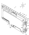
遊技機は、図6に示したように、四角い枠状の外枠1と、その外枠1の前面に横開きの扉状に取り付けた前枠2と、その前枠2の後面に取り付けた機構盤3と、を有する。前記機構盤3は、前枠2に着脱交換可能な状態に装着された遊技板(図示せず)の後面を覆うように取り付けられており、遊技球を貯留する球タンク4と、その球タンク4の遊技球を下方に流す導出樋5と、その導出樋5の遊技球を入賞の景品として遊技者に放出する景品球放出装置6と、を備え、さらに遊技に関わる制御を行う制御装置7を備えている。
[All gaming machines]
As shown in FIG. 6, the gaming machine is attached to a square frame-shaped outer frame 1, a
[制御装置]
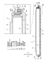
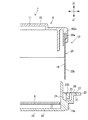
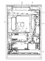
前記制御装置7は、図3、図4に示したように、内部中空の箱構造である基板ボックス8に、CPUやメモリー等の電子部品(図示省略)を搭載した制御基板9を収納したものである。
[Control device]
As shown in FIGS. 3 and 4, the
[基板ボックス]
前記基板ボックス8は、蓋付き箱の「身」に相当するベース体10と、蓋付き箱の「蓋」に相当するカバー体11と、ベース体10にカバー体11を被せた状態で封印する封印手段12と、から概略構成される。
[Board box]
The
[基板ボックス−ベース体]
前記ベース体10は、例えばポリカーボネート等の透明な硬質の合成樹脂製であって、前記機構盤3に当接する横長長方形状の前面部材13と、該前面部材13の四辺から後ろ向きに突設した側枠部材14a〜14dと、を有しており、全体として後面が開口したトレー状になっている。
[Substrate box-base body]
The
[基板ボックス−カバー体]
前記カバー体11は、例えばポリカーボネート等の透明な硬質の合成樹脂製であって、前記ベース体10の前面部材13に対向位置する後面部材15と、該後面部材15の周囲を囲うように前向きに突設した周枠部材16a〜16dと、からなり、全体として前面開口状に形成されていている。
かかるカバー体11は、周枠部材16a〜16dの開口サイズがベース体10の前記側枠部材14a〜14dの開口サイズより一回り小さくなっており、したがってベース体10の側枠部材14a〜14dの内側にカバー体11の周枠部材16a〜16dが嵌まる。
[Substrate box-cover body]
The
In the
ベース体10とカバー体11の図3、図4において左横の側枠部材14cと周枠部材16cは、接合・分離可能な蝶番構造になっている。具体的には、ベース体10の側枠部材14cに逆さU溝状の袋部17を設け、一方、カバー体11の周枠部材16cにL形鉤部18を設け、このカバー体11のL形鉤部18をベース体10の袋部17に回り込ませつつ係合させることにより、カバー体11をベース体10に対して回動可能且つ分離可能に接合している。
3 and 4 of the
[封印手段]
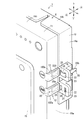
封印手段12は、ベース体10とカバー体11とを接合して封印し且つ封印解除に際して自己の破壊(切断)を要するものであって、少なくとも一つの外表面に鋸歯(図示省略)状の噛合部19が形成された可撓性を有する樹脂製バンド20と、該樹脂製バンド20の挿通を可能とし且つ引き抜きを不能とするように前記噛合部19に噛み合う爪(図示省略)状の被噛合部21が形成された受孔部22と、のあたかもラチェット機構のごとき要素の組み合わせで構成され、実施形態では樹脂製バンド20がカバー体11に、また、受孔部22がベース体10に設けられている。
[Sealing means]
The sealing means 12 joins and seals the
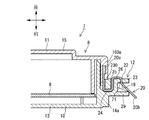
[封印手段−樹脂製バンド]
実施形態の樹脂製バンド20は、例えば赤や黄色などの目立ちやすい色に着色されたナイロン製で、厚い板状の基部20aと、薄くて柔軟な帯状のバンド本体20bで形成されており、前記カバー体11の一つの周枠部材16aから一体に膨出させたバンド支持部160aの内部に前記基部20aが埋め込まれると共に該バンド支持部160aの端部からバンド本体20bが外部に突出するようになっている。この樹脂製バンド20は、具体的にはカバー体11を樹脂成形品としてその樹脂(金型)成形時に前記基部20aをインサート成形により一体成形するようになっている。
[Sealing means-resin band]
The
[封印手段−受孔部]
実施形態の受孔部22は、ベース体10の一つの側枠部材14aに突設された突片23に形成されており、その被噛合部21は、その爪の形が、前記樹脂製バンド20のバンド本体20bが受孔部22を後から前に貫く挿通を可能とし且つ逆方向への引き抜きを不能とする向きに設定されている。
[Sealing means-receiving hole]
The receiving
ところで、ベース体10の突片23と側枠部材14aには、図3に示したように、カバー体11から飛び出た樹脂製バンド20のバンド本体20bをベース体10側(具体的には突片23の受孔部22の横)に導くためのトンネル通路24が形成されており、このトンネル通路24の出口25と受孔部22の間がバンド本体20bを切断するのに適したまな板状の切断部26になっている。
このようにカバー体11側の樹脂製バンド20を、トンネル通路24を潜らせて外部に露出させることなくベース体10側の切断部26に導出させるようにすれば、樹脂製バンド20の切断箇所がトンネル通路24の出口25以降に限定される。
一方、樹脂製バンド20は、受孔部22の被噛合部21を抜けた先の部分をどこで切断しても封印状態は変わらない。
よって、実施形態の封印手段12は、樹脂製バンド20を切断して封印を解除する部分が前記切断部26に限定されるため、封印解除の状態が一見して明らかであり、したがって、例えば切断部26以外の目立ちにくい場所を切断して封印解除の事実を隠蔽する、というような偽装工作のおそれが殆どない。
なお、実施形態では、図3、図4に示したように、ベース体10の突片23の基部とカバー体11のバンド支持部160aの端面とを噛合させることにより、具体的にはベース体10の突片23の基部の後面側に形成した凹部230にカバー体11のバンド支持部160aの端面を嵌め合わせることにより、トンネル通路24の途中にカミソリの刃のような薄い切断具が差し込まれないようになっている。
By the way, as shown in FIG. 3, the
Thus, if the
On the other hand, the sealing state of the
Accordingly, the sealing means 12 of the embodiment is limited to the cutting
In the embodiment, as shown in FIGS. 3 and 4, the
以上の封印手段12は、図1、図2においてカバー体11の縁に丸囲いの「1」と刻印されているものに対応するものと、同じく丸囲いの「2」に対応するものとがある。
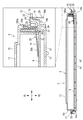
なお、丸囲いの「1」に対応する封印手段12と丸囲いの「2」に対応する封印手段12は殆ど同じであるが、丸囲いの「2」に対応する封印手段12には、図4に示したように、前記トンネル通路24の屈曲部に設けられた山形の振分け部27と、その振分け部27から基板ボックス8内に通じる収納路28が別途付加されており、したがって、未使用の樹脂製バンド20が振分け部27から収納路28を通って基板ボックス8の制御基板9側に引き出し可能な状態に収納される。
The sealing means 12 described above corresponds to those corresponding to those in which the edge of the
It should be noted that the sealing means 12 corresponding to the round enclosure “1” and the sealing means 12 corresponding to the round enclosure “2” are almost the same. As shown in FIG. 4, a mountain-shaped
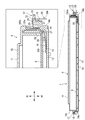
以上のように構成される封印手段12は、図5のようにベース体10とカバー体11が分離している状態で、全ての樹脂製バンド20のバンド本体20bがカバー体11のバンド支持部160aの端面から飛び出した状態になっている。
The sealing means 12 configured as described above is such that the
そして、この状態で図3、図4においてカバー体11の左横側のL形鉤部18をベース体10の袋部17に回り込ませつつ係合させ、一方、カバー体11の右横側に飛び出た全ての樹脂製バンド20の先を対応する夫々のトンネル通路24に差し込みつつ最終的にベース体10にカバー体11を被せてとじ合わせる。
In this state, in FIG. 3 and FIG. 4, the L-shaped
そうすると丸囲いの「1」に対応する樹脂製バンド20は、バンド本体20bがトンネル通路24に沿ってU字状にターンして出口25から突片23の後面側に突出するから、その突片23の出口25から出たバンド本体20bを手で掴んでその先を受孔部22に差し込み、さらに受孔部22の反対側からバンド本体20bの先を引っ張って締める。前記のように樹脂製バンド20は、受孔部22に通すと逆向きに戻らないようになっているため、樹脂製バンド20で締められたベース体10とカバー体11は、封印された状態に固定される。
なお、こうして封印された状態は、透明なベース体10とカバー体11の内部を通って切断部26に至るまでの樹脂製バンド20を目視で確認することでチェック可能であるが、その際、実施形態のように樹脂製バンド20の色を赤や黄色の目立ちやすい色にしておけば、チェックの確実性及び効率性を高めることができる。
Then, the
The sealed state can be checked by visually confirming the
一方、丸囲いの「2」に対応する樹脂製バンド20は、前記のようにトンネル通路24に差し込む段階で、バンド本体20bが制御基板9側に若干傾くように指先で加減をする。そうすることで、バンド本体20bが図4のようにトンネル通路24の振分け部27を通って収納路28側に曲がるため、そのまま基板ボックス8の制御基板9側に収納される。
なお、実施形態では、樹脂製バンド20のバンド本体20bが制御基板9の上面に導かれるようになっているが、そのバンド本体20bによって制御基板9に電気的な不都合が生ずるおそれがある場合は、図7に示したようにバンド本体20bを制御基板9とベース体10の間に導いたり、或は、図示しないが制御基板9の上に別の基板を配置してその基板の上にバンド本体20bを導くようにしてもよい。
On the other hand, the
In the embodiment, the band
以上のようにして丸囲いの「1」に対応する封印手段12で封印された基板ボックス8の該封印を、監督官庁が制御基板9の検査を行うために解除する場合は、突片23の出口25と受孔部22の間の切断部26上にあるバンド本体20bをカッター等の切断具で切断すればよい。
なお、丸囲いの「2」に対応する封印手段12のバンド本体20bは、検査のためにカバー体11をベース体10から外したとき、カバー体11に引っ張られてトンネル通路24から抜ける。
When the supervisory agency releases the seal of the
The band
そして、上記の検査が終了した後は、残った丸囲いの「2」に対応する樹脂製バンド20を前記と同様にトンネル通路24に差し込みつつベース体10にカバー体11を被せる。このとき樹脂製バンド20のバンド本体20bが若干突片23側に傾くように指先で加減をすれば、トンネル通路24の振分け部27で突片23側に案内され、そのままトンネル通路24の出口25から突片23の後面側に突出する。以後の操作は前記した丸囲いの「1」に対応する樹脂製バンド20と同じであるため説明を省略する。
Then, after the above inspection is completed, the
以上、本発明を実施の形態について説明したが、もちろん本発明は上記実施形態に限定されるものではない。例えば実施形態では、遊技機としてパチンコ機を例示したが、スロットマシン、その他の遊技機にも同様に適用できる。 As mentioned above, although embodiment of this invention was described, of course, this invention is not limited to the said embodiment. For example, in the embodiment, a pachinko machine is illustrated as a gaming machine, but the present invention can be similarly applied to a slot machine and other gaming machines.
また、実施形態では、図3に示したように、封印状態の樹脂製バンド20の先が突片23の前方に真っ直ぐ向かうようになっているが、例えば図8に示したように突片23の前方に案内片29を突設し、そうして封印状態の樹脂製バンド20の先が外向きに曲がるように案内してもよい。そうすることにより突片23越しに樹脂製バンド20の先端が目視で確認できるため、樹脂製バンド20に不正工作が行われていないことの確認がより確実になる。
また、これとは逆に突片23の前方を嵌め殺しの透明キャップ(図示せず)で覆って樹脂製バンド20の先を封じ込めるようにしてもよい。この場合には、樹脂製バンド20のバンド本体20aを切断してその切断部を隠す、という不正が万一行われたとしても、受孔部22を通ったバンド本体20aの先が前記透明キャップに妨げられて引っ張れないため、実体はもちろん見かけ上も完全な封印状態に戻すことが困難になる。
Further, in the embodiment, as shown in FIG. 3, the tip of the
Alternatively, the tip of the
また、実施形態では、ベース体10とカバー体11の封印後の固定を封印手段12で行うようにしたが、封印手段12とは別に着脱可能なネジ等の固定手段を設けるようにしてもよい。そうすることにより封印手段12の樹脂製バンド20を細く安価にすることができる。
また、実施形態の樹脂製バンド20は、複数個設けられていてその全てが同色になっているが、複数個の樹脂製バンド20を複数色に色分けしてもよい。そうすることにより色数に応じて3Dプリンターの高機能化が必要になるため、不正を目的とする複製品の作成をより困難にすることができる。
In the embodiment, the
Further, a plurality of
また、実施形態では樹脂製バンド20の一つの外表面に噛合部19を設けるようにしたが、該噛合部19を両面に設けるようにしてもよい。これにより樹脂製バンド20の強制的な引き抜きをより困難にすることができる。
さらにまた、実施形態では樹脂製バンド20をカバー体11に、また、受孔部22をベース体10に設けるようにしたが、逆に樹脂製バンド20をベース体10に、受孔部22をカバー体11に設けるようにしてもよい。
Further, in the embodiment, the
Furthermore, in the embodiment, the
7 …制御装置
8 …基板ボックス
9 …制御基板
10 …ベース体
11 …カバー体
12 …封印手段
19 …噛合部
20 …樹脂製バンド
20a …基部
21 …被噛合部
22 …受孔部
DESCRIPTION OF
Claims (2)
前記基板ボックスは、
設置時の状態で遊技者に近い側を「前」、反対側を「後」としたとき、前側に位置するベース体と、
該ベース体の後側をカバーするカバー体と、
前記ベース体と前記カバー体とを接合した状態で封印し且つ封印解除に際して自己の破壊を要する封印手段と、を有するものである遊技機において、
前記封印手段は、
少なくとも一つの外表面に噛合部が形成された可撓性を有する樹脂製バンドと、該樹脂製バンドの一方向の挿通を可能とし逆方向への引き抜きを不能とするように前記噛合部に噛み合う被噛合部が形成された受孔部と、の組み合わせで構成されるものであって、
前記ベース体又は前記カバー体の何れか一方の部材を硬質の樹脂成形品としてその樹脂成形時に前記樹脂製バンドの基部をインサート成形により一体成形すると共に他方の部材に前記受孔部を形成してなり、
前記樹脂製バンドを切断して封印解除するものであることを特徴とする遊技機。 It has a control device that encloses the control board inside the board box,
The board box is
The base body located on the front side when the side close to the player in the installed state is `` front '' and the opposite side is `` rear '',
A cover body covering the rear side of the base body;
In a gaming machine having sealing means that seals the base body and the cover body in a joined state and requires self-breakage when releasing the seal,
The sealing means is
A flexible resin band having a meshing portion formed on at least one outer surface, and meshing with the meshing portion so that the resin band can be inserted in one direction and cannot be pulled out in the reverse direction. It is composed of a combination with a receiving hole portion in which a meshed portion is formed,
Either one of the base body or the cover body is formed as a hard resin molded product, and the base portion of the resin band is integrally formed by insert molding at the time of resin molding, and the receiving hole portion is formed in the other member. Become
A gaming machine that cuts the resin band to release the seal.
Priority Applications (1)
| Application Number | Priority Date | Filing Date | Title |
|---|---|---|---|
| JP2013211846A JP2015073732A (en) | 2013-10-09 | 2013-10-09 | Game machine |
Applications Claiming Priority (1)
| Application Number | Priority Date | Filing Date | Title |
|---|---|---|---|
| JP2013211846A JP2015073732A (en) | 2013-10-09 | 2013-10-09 | Game machine |
Publications (1)
| Publication Number | Publication Date |
|---|---|
| JP2015073732A true JP2015073732A (en) | 2015-04-20 |
Family
ID=52999060
Family Applications (1)
| Application Number | Title | Priority Date | Filing Date |
|---|---|---|---|
| JP2013211846A Pending JP2015073732A (en) | 2013-10-09 | 2013-10-09 | Game machine |
Country Status (1)
| Country | Link |
|---|---|
| JP (1) | JP2015073732A (en) |
Citations (6)
| Publication number | Priority date | Publication date | Assignee | Title |
|---|---|---|---|---|
| JPH09201449A (en) * | 1996-01-27 | 1997-08-05 | Sankyo Kk | Box for storing circuit board in game machine |
| JPH10192515A (en) * | 1996-12-27 | 1998-07-28 | Toyomaru Sangyo Kk | Control box for game machine |
| JP2001300091A (en) * | 2000-04-21 | 2001-10-30 | Sanyo Product Co Ltd | Game machine |
| JP2001314624A (en) * | 2000-05-11 | 2001-11-13 | Daiichi Shokai Co Ltd | Amusement machine board case |
| JP2010075499A (en) * | 2008-09-26 | 2010-04-08 | Sammy Corp | Seal protective member, electronic board unit, game machine, and board case |
| JP2012115327A (en) * | 2010-11-29 | 2012-06-21 | Sanyo Product Co Ltd | Game machine |
-
2013
- 2013-10-09 JP JP2013211846A patent/JP2015073732A/en active Pending
Patent Citations (6)
| Publication number | Priority date | Publication date | Assignee | Title |
|---|---|---|---|---|
| JPH09201449A (en) * | 1996-01-27 | 1997-08-05 | Sankyo Kk | Box for storing circuit board in game machine |
| JPH10192515A (en) * | 1996-12-27 | 1998-07-28 | Toyomaru Sangyo Kk | Control box for game machine |
| JP2001300091A (en) * | 2000-04-21 | 2001-10-30 | Sanyo Product Co Ltd | Game machine |
| JP2001314624A (en) * | 2000-05-11 | 2001-11-13 | Daiichi Shokai Co Ltd | Amusement machine board case |
| JP2010075499A (en) * | 2008-09-26 | 2010-04-08 | Sammy Corp | Seal protective member, electronic board unit, game machine, and board case |
| JP2012115327A (en) * | 2010-11-29 | 2012-06-21 | Sanyo Product Co Ltd | Game machine |
Similar Documents
| Publication | Publication Date | Title |
|---|---|---|
| JP5821470B2 (en) | Game machine | |
| JP2015073732A (en) | Game machine | |
| JP5761246B2 (en) | Game machine | |
| JP5656033B2 (en) | Game machine | |
| JP2007061470A (en) | Control board-sealing structure used for board storing case, and control board-sealing method | |
| JP4905718B2 (en) | Board case | |
| JP2014204919A (en) | Game machine | |
| JP3119194B2 (en) | Gaming machine control box | |
| JP6057291B2 (en) | PCB case unit | |
| JP2015221244A (en) | Game machine | |
| JP6049547B2 (en) | Game machine | |
| JP6557179B2 (en) | Game machine | |
| JP2017221405A (en) | Game machine | |
| JP5835843B2 (en) | Electronic board unit and game machine | |
| JP4922133B2 (en) | Gaming machine and board case for gaming machine | |
| JP5892667B2 (en) | Board case | |
| JP5836303B2 (en) | Game machine | |
| JP5208486B2 (en) | Game board control board unit | |
| JP6743228B2 (en) | Amusement machine | |
| JP5876964B1 (en) | Cover with sealing member for gaming machine and gaming machine | |
| JP6236137B2 (en) | Game machine | |
| JP6712693B2 (en) | Amusement machine | |
| JP5224026B2 (en) | Game machine | |
| JP6290340B2 (en) | Game board control board unit | |
| JP5354061B2 (en) | Game machine board case |
Legal Events
| Date | Code | Title | Description |
|---|---|---|---|
| A621 | Written request for application examination |
Free format text: JAPANESE INTERMEDIATE CODE: A621 Effective date: 20161011 |
|
| A131 | Notification of reasons for refusal |
Free format text: JAPANESE INTERMEDIATE CODE: A131 Effective date: 20170802 |
|
| A977 | Report on retrieval |
Free format text: JAPANESE INTERMEDIATE CODE: A971007 Effective date: 20170731 |
|
| A02 | Decision of refusal |
Free format text: JAPANESE INTERMEDIATE CODE: A02 Effective date: 20180207 |