JP4620109B2 - Radiopaque coatings for biomedical devices - Google Patents
Radiopaque coatings for biomedical devices Download PDFInfo
- Publication number
- JP4620109B2 JP4620109B2 JP2007505130A JP2007505130A JP4620109B2 JP 4620109 B2 JP4620109 B2 JP 4620109B2 JP 2007505130 A JP2007505130 A JP 2007505130A JP 2007505130 A JP2007505130 A JP 2007505130A JP 4620109 B2 JP4620109 B2 JP 4620109B2
- Authority
- JP
- Japan
- Prior art keywords
- medical device
- coating
- stent
- voltage
- target
- Prior art date
- Legal status (The legal status is an assumption and is not a legal conclusion. Google has not performed a legal analysis and makes no representation as to the accuracy of the status listed.)
- Expired - Fee Related
Links
Images


Classifications
-
- C—CHEMISTRY; METALLURGY
- C23—COATING METALLIC MATERIAL; COATING MATERIAL WITH METALLIC MATERIAL; CHEMICAL SURFACE TREATMENT; DIFFUSION TREATMENT OF METALLIC MATERIAL; COATING BY VACUUM EVAPORATION, BY SPUTTERING, BY ION IMPLANTATION OR BY CHEMICAL VAPOUR DEPOSITION, IN GENERAL; INHIBITING CORROSION OF METALLIC MATERIAL OR INCRUSTATION IN GENERAL
- C23C—COATING METALLIC MATERIAL; COATING MATERIAL WITH METALLIC MATERIAL; SURFACE TREATMENT OF METALLIC MATERIAL BY DIFFUSION INTO THE SURFACE, BY CHEMICAL CONVERSION OR SUBSTITUTION; COATING BY VACUUM EVAPORATION, BY SPUTTERING, BY ION IMPLANTATION OR BY CHEMICAL VAPOUR DEPOSITION, IN GENERAL
- C23C14/00—Coating by vacuum evaporation, by sputtering or by ion implantation of the coating forming material
- C23C14/06—Coating by vacuum evaporation, by sputtering or by ion implantation of the coating forming material characterised by the coating material
- C23C14/14—Metallic material, boron or silicon
- C23C14/16—Metallic material, boron or silicon on metallic substrates or on substrates of boron or silicon
- C23C14/165—Metallic material, boron or silicon on metallic substrates or on substrates of boron or silicon by cathodic sputtering
-
- A—HUMAN NECESSITIES
- A61—MEDICAL OR VETERINARY SCIENCE; HYGIENE
- A61L—METHODS OR APPARATUS FOR STERILISING MATERIALS OR OBJECTS IN GENERAL; DISINFECTION, STERILISATION OR DEODORISATION OF AIR; CHEMICAL ASPECTS OF BANDAGES, DRESSINGS, ABSORBENT PADS OR SURGICAL ARTICLES; MATERIALS FOR BANDAGES, DRESSINGS, ABSORBENT PADS OR SURGICAL ARTICLES
- A61L31/00—Materials for other surgical articles, e.g. stents, stent-grafts, shunts, surgical drapes, guide wires, materials for adhesion prevention, occluding devices, surgical gloves, tissue fixation devices
- A61L31/08—Materials for coatings
- A61L31/082—Inorganic materials
- A61L31/088—Other specific inorganic materials not covered by A61L31/084 or A61L31/086
-
- A—HUMAN NECESSITIES
- A61—MEDICAL OR VETERINARY SCIENCE; HYGIENE
- A61L—METHODS OR APPARATUS FOR STERILISING MATERIALS OR OBJECTS IN GENERAL; DISINFECTION, STERILISATION OR DEODORISATION OF AIR; CHEMICAL ASPECTS OF BANDAGES, DRESSINGS, ABSORBENT PADS OR SURGICAL ARTICLES; MATERIALS FOR BANDAGES, DRESSINGS, ABSORBENT PADS OR SURGICAL ARTICLES
- A61L31/00—Materials for other surgical articles, e.g. stents, stent-grafts, shunts, surgical drapes, guide wires, materials for adhesion prevention, occluding devices, surgical gloves, tissue fixation devices
- A61L31/14—Materials characterised by their function or physical properties, e.g. injectable or lubricating compositions, shape-memory materials, surface modified materials
- A61L31/146—Porous materials, e.g. foams or sponges
-
- A—HUMAN NECESSITIES
- A61—MEDICAL OR VETERINARY SCIENCE; HYGIENE
- A61L—METHODS OR APPARATUS FOR STERILISING MATERIALS OR OBJECTS IN GENERAL; DISINFECTION, STERILISATION OR DEODORISATION OF AIR; CHEMICAL ASPECTS OF BANDAGES, DRESSINGS, ABSORBENT PADS OR SURGICAL ARTICLES; MATERIALS FOR BANDAGES, DRESSINGS, ABSORBENT PADS OR SURGICAL ARTICLES
- A61L31/00—Materials for other surgical articles, e.g. stents, stent-grafts, shunts, surgical drapes, guide wires, materials for adhesion prevention, occluding devices, surgical gloves, tissue fixation devices
- A61L31/14—Materials characterised by their function or physical properties, e.g. injectable or lubricating compositions, shape-memory materials, surface modified materials
- A61L31/18—Materials at least partially X-ray or laser opaque
-
- C—CHEMISTRY; METALLURGY
- C23—COATING METALLIC MATERIAL; COATING MATERIAL WITH METALLIC MATERIAL; CHEMICAL SURFACE TREATMENT; DIFFUSION TREATMENT OF METALLIC MATERIAL; COATING BY VACUUM EVAPORATION, BY SPUTTERING, BY ION IMPLANTATION OR BY CHEMICAL VAPOUR DEPOSITION, IN GENERAL; INHIBITING CORROSION OF METALLIC MATERIAL OR INCRUSTATION IN GENERAL
- C23C—COATING METALLIC MATERIAL; COATING MATERIAL WITH METALLIC MATERIAL; SURFACE TREATMENT OF METALLIC MATERIAL BY DIFFUSION INTO THE SURFACE, BY CHEMICAL CONVERSION OR SUBSTITUTION; COATING BY VACUUM EVAPORATION, BY SPUTTERING, BY ION IMPLANTATION OR BY CHEMICAL VAPOUR DEPOSITION, IN GENERAL
- C23C14/00—Coating by vacuum evaporation, by sputtering or by ion implantation of the coating forming material
- C23C14/22—Coating by vacuum evaporation, by sputtering or by ion implantation of the coating forming material characterised by the process of coating
- C23C14/34—Sputtering
- C23C14/3435—Applying energy to the substrate during sputtering
- C23C14/345—Applying energy to the substrate during sputtering using substrate bias
Landscapes
- Health & Medical Sciences (AREA)
- Chemical & Material Sciences (AREA)
- Epidemiology (AREA)
- Surgery (AREA)
- Public Health (AREA)
- Vascular Medicine (AREA)
- Heart & Thoracic Surgery (AREA)
- Life Sciences & Earth Sciences (AREA)
- Animal Behavior & Ethology (AREA)
- General Health & Medical Sciences (AREA)
- Veterinary Medicine (AREA)
- Mechanical Engineering (AREA)
- Chemical Kinetics & Catalysis (AREA)
- Materials Engineering (AREA)
- Engineering & Computer Science (AREA)
- Metallurgy (AREA)
- Inorganic Chemistry (AREA)
- Organic Chemistry (AREA)
- Physics & Mathematics (AREA)
- Dispersion Chemistry (AREA)
- Optics & Photonics (AREA)
- Materials For Medical Uses (AREA)
- Physical Vapour Deposition (AREA)
- Media Introduction/Drainage Providing Device (AREA)
Description
〔関連出願〕
本願は、2004年3月23日出願の米国仮特許出願第60/555,721号および2004年6月14日出願の同第60/579,577号の恩典を請求するものであり、2004年1月22日出願の米国仮特許出願第60/538,749号の恩典を請求する2005年1月21日出願の米国特許出願第11/040,433号の一部継続出願である。これらの特許文献は、参照することを以って、一部または全ての目的のための開示内容を本明細書の一部とする。
[Related applications]
This application claims the benefit of US Provisional Patent Application No. 60 / 555,721 filed Mar. 23, 2004 and 60 / 579,577 filed Jun. 14, 2004, 2004. This is a continuation-in-part of US patent application Ser. No. 11 / 040,433, filed Jan. 21, 2005, claiming the benefit of US Provisional Patent Application No. 60 / 538,749, filed Jan. 22. These patent documents are hereby incorporated by reference in their entirety for some or all purposes.
〔発明の分野〕
本発明は、医療装置に関する。
(Field of the Invention)
The present invention relates to a medical device.
〔発明の背景〕
ステントは、心血管疾患の治療において極めて重要な装置になった。ステントは、動脈内に配置でき、その動脈を開存させて十分な血流を維持する小さなメッシュ「足場」である。一般に、ステントは、上腕動脈または大腿動脈を介して患者の器官内に導入され、カテーテルおよびガイドワイヤを用いて所定の位置まで送られる。この最小侵襲性処置は、外科手術の代替法であり、患者の看護およびコスト面で大きな利点が得られるため、現在では、広く用いられるようになってきた。
BACKGROUND OF THE INVENTION
Stents have become a vital device in the treatment of cardiovascular disease. A stent is a small mesh “scaffold” that can be placed in an artery and patency the artery to maintain sufficient blood flow. Generally, a stent is introduced into a patient's organ via the brachial artery or femoral artery and delivered to a predetermined location using a catheter and guide wire. This minimally invasive procedure is an alternative to surgery and has gained widespread use today because it offers significant benefits in terms of patient care and cost.
ステントを配置する際は、所望の位置まで送達できるように通常の直径の数分の1まで圧縮しなければならない。したがって、多くのステントおよびガイドワイヤは、特殊な超弾性特性および形状記憶特性を有するニチノールとして知られているニッケルチタン合金から形成されている。これらの特性はともに、ニチノールが、Mfとして知られている第1の変態温度未満のマルテンサイト相およびAfとして知られている第2の変態温度よりも高いオーステナイト相で存在するという事実に起因する。MfおよびAfはともに、合金におけるチタンに対するニッケルの比率および材料の熱処理によって操作することができる。マルテンサイト相では、ニチノールは、高い延性を有し、容易に変形させることができるが、オーステナイト相では、高い弾性係数を有する。応力がかかると、Afよりも温度が高いある種のマルテンサイト物質になり、応力が除去されるとこの物質が元の形状に戻る。これにより、超弾性特性すなわち擬似弾性(pseudoelasticity)と呼ばれるニチノールの極めて高い弾性が得られる。さらに、Mf未満の低い温度に下げられてニチノールが変形された場合、温度がAfよりも上昇すると元の形状に戻る。これが、形状記憶特性である。 When placing a stent, it must be compressed to a fraction of its normal diameter so that it can be delivered to the desired location. Thus, many stents and guidewires are formed from a nickel titanium alloy known as Nitinol, which has special superelastic and shape memory properties. Both of these properties are due to the fact that nitinol is present in the martensite phase below the first transformation temperature known as M f and in the austenite phase higher than the second transformation temperature known as A f. to cause. Both M f and A f can be manipulated by the ratio of nickel to titanium in the alloy and the heat treatment of the material. In the martensite phase, nitinol has high ductility and can be easily deformed, whereas in the austenite phase, it has a high elastic modulus. When stress is applied, it becomes a kind of martensitic material having a temperature higher than A f , and when the stress is removed, this material returns to its original shape. This provides a very high elasticity of Nitinol called superelastic properties, ie pseudoelasticity. Furthermore, when Nitinol is deformed by being lowered to a temperature lower than M f , it returns to its original shape when the temperature rises above A f . This is the shape memory characteristic.
超弾性特性および形状記憶特性を有するステントは、小さな直径に圧縮して所定の位置に移動させてから、完全な大きさに戻せるように配置する。通常の体温よりも低いAfを有する合金組成を選択することにより、一旦配置されると、ステントは大きな力で拡張状態が維持される。驚くべきことに、ニチノールは、この手順の際に通常は8%もの歪み変形に耐えなければならない。 Stents with superelastic and shape memory properties are placed so that they can be compressed to a small diameter, moved into place and then returned to full size. By choosing an alloy composition with an A f that is lower than normal body temperature, once deployed, the stent remains expanded with great force. Surprisingly, nitinol must withstand strain deformations typically as much as 8% during this procedure.
ステントおよび同様の腔内装置は、ステンレス鋼または他の合金から形成することもできる。このような金属は、形状記憶特性や超弾性特性を有していないが、このような材料から形成したステントも、使用中に著しい歪み変形に耐えなければならない。 Stents and similar intraluminal devices can also be formed from stainless steel or other alloys. Such metals do not have shape memory or superelastic properties, but stents formed from such materials must also withstand significant strain deformation during use.
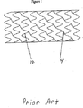
図1は、この圧縮と拡張を容易にするために用いられる多数のステントデザインの1つを例示している。このデザインは、リング型「ストラット」12を用いている。各ストラットは、小さな直径に収縮可能にする波形構造を有する。ノードとも呼ぶブリッジ14が、ストラットを連結している。このブリッジ14も、使用の際に屈曲しなければならない。螺旋デザイン、編組デザイン、織デザイン、およびコイルなどの様々な他のタイプの拡張可能な形状が、当分野で知られており、様々な目的で用いられている。
FIG. 1 illustrates one of a number of stent designs that can be used to facilitate this compression and expansion. This design uses a ring-type “strut” 12. Each strut has a corrugated structure that allows it to contract to a small diameter. A
ニチノールおよび様々な他の合金から形成されるステントの1つの問題は、よく使用される金属の原子番号が小さいため、X線の吸収が比較的弱いといことである。したがって、通常の寸法のステントは、操作する際および所定の位置にある際にX線で視認するのが困難であるかまたは不可能である。このような装置は、放射線透過性と呼ばれる。ステントをX線で視認できると、多くの利点が得られる。例えば、いわゆる放射線不透過性により、初めにステントを正確に配置することができ、ステントが所定の位置に配置されたら、医学的に重要な症状を反映しうる形状の変化を確認することができる。 One problem with stents formed from Nitinol and various other alloys is that the X-ray absorption is relatively weak due to the small atomic number of commonly used metals. Thus, a normal sized stent is difficult or impossible to view with x-rays when maneuvering and in place. Such a device is called radiolucent. Many advantages are obtained when the stent is visible with X-rays. For example, so-called radiopacity allows the stent to be accurately placed initially, and once the stent is in place, changes in shape that can reflect medically important symptoms can be identified. .
ステントまたはその一部に放射線不透過性を付与する様々な方法が従来技術に開示されている。このような従来技術には、ステントのキャビティを放射線不透過材料で充填する(米国特許第6,635,082号、同第6,641,607号)、放射線不透過性マーカーをステントに取り付ける(米国特許第6,293,966号、同第6,312,456号、同第6,334,871号、同第6,361,557号、同第6,402,777号、同第6,497,671号、同第6,503,271号、同第6,554,854号)、放射線不透過性が異なる複層材料を含むステント(米国特許第6,638,301号、同第6,620,192号)、ステントに放射線不透過性構造要素を含める(米国特許第6,464,723号、同第6,471,721号、同第6,540,774号、同第6,585,757号、同第6,652,579号)、放射線不透過粒子を含む結合剤でコーティングする(米国特許第6,355,058号)、およびステントに放射線不透過性材料をスプレーコーティングする方法(米国特許第6,616,765号)が含まれる。 Various methods for imparting radiopacity to a stent or portion thereof have been disclosed in the prior art. In such prior art, the stent cavity is filled with a radiopaque material (US Pat. Nos. 6,635,082, 6,641,607) and radiopaque markers are attached to the stent ( U.S. Patent Nos. 6,293,966, 6,312,456, 6,334,871, 6,361,557, 6,402,777, 497,671, 6,503,271, 6,554,854), stents containing multilayer materials with different radiopacity (US Pat. Nos. 6,638,301, 6) , 620, 192), including a radiopaque structural element in the stent (US Pat. Nos. 6,464,723, 6,471,721, 6,540,774, 6, No. 585,757, No. 6,65 579), coating with a binder containing radiopaque particles (US Pat. No. 6,355,058), and spray coating a radiopaque material onto a stent (US Pat. No. 6,616,765). Issue).
ステントに放射線不透過性を付与するこれらの全ての従来技術の方法では、製造コストおよび複雑さが大幅に増大し、かつ/またはステントの放射線不透過性がほんの一部にしか付与されない。最も効率的な方法は、ステントの全ての表面に、単に、十分に密度の高い放射線不透過性材料のコンフォーマルコーティングを施すことである。このようなコーティングは、良好なX線コントラスト、生体適合性、および腐食耐性が得られるように十分な厚みを有する必要がある。しかしながら、より困難なことに、このようなコーティングは、クラックや剥離が起こることなく、使用の際に生じる極端な歪みに耐えることができ、かつステントの重要な熱機械特性が維持される十分な延性を有していなければならない。加えて、このようなコーティングは、心臓の鼓動で血管が伸縮するために生じるステントの不断の伸縮に耐えなければならない。 All these prior art methods of imparting radiopacity to a stent significantly increase manufacturing costs and complexity and / or impart only a fraction of the radiopacity of the stent. The most efficient method is simply to apply a conformal coating of sufficiently dense radiopaque material to all surfaces of the stent. Such a coating must have a sufficient thickness to provide good X-ray contrast, biocompatibility, and corrosion resistance. More difficultly, however, such coatings can withstand extreme strains in use without cracking and debonding, and are sufficient to maintain the important thermomechanical properties of the stent. Must have ductility. In addition, such coatings must withstand the constant expansion and contraction of the stent caused by the expansion and contraction of blood vessels in the heartbeat.
スパッタリング、熱蒸着(thermal evaporation)、および陰極アーク蒸着(cathodic arc deposition)などの物理蒸着法により、金、プラチナ、タンタル、およびタングステンなどのような放射性不透過性材料の密度の高いコンフォーマルコーティングを施すことができる。物理蒸着は、広く使用されており、信頼できるものである。しかしながら、このような方法で形成されるコーティングは通常、本明細書で要求するように、最大8%の歪みを受ける基材に十分に付着していることができない。この問題は、米国特許第6,174,329号で指摘されており、ステントの使用中に放射線不透過性コーティングが剥離するのを防止するべく放射線不透過性コーティングの上に保護コーティングを施す必要性について言及している。 High density conformal coatings of radiopaque materials such as gold, platinum, tantalum, and tungsten by physical vapor deposition methods such as sputtering, thermal evaporation, and cathodic arc deposition Can be applied. Physical vapor deposition is widely used and reliable. However, coatings formed by such methods usually cannot adhere well to substrates that experience up to 8% strain, as required herein. This problem is pointed out in US Pat. No. 6,174,329, and it is necessary to apply a protective coating over the radiopaque coating to prevent the radiopaque coating from peeling off during use of the stent. Mentions sex.
物理蒸着によって蒸着される放射線不透過性コーティングの別の重要な制限は、ニチノールおよび他のステント材料の温度感受性である。上記したように、形状記憶バイオメディカル装置は、通常の体温よりも僅かに低いAfの値で形成されている。ニチノールが、過度に長い時間に亘って過度に高い温度に持続されると、ニチノールのAf値が上昇し、300℃〜400℃を超える温度の持続により、ステントに一般的に用いられるAf値に悪影響が及ぼされる。同様に、ステンレス鋼も過度に高い温度に上昇すると、劣化しうる。他のステント材料も、悪影響を受けるであろう。したがって、コーティング中のステントの時間と温度の履歴が極めて重要である。従来技術では、このような場合、特にステントなどの極めて低い熱質量(thermal mass)を有するような基材の温度を直接制御するのが慣習である。これは通常、温度が制御されている大きな質量すなわちヒートシンクに熱接触するように基材を配置して行われる。この方法は、温度の直接制御として知られている。ステントの形状および構造から、コーティングの際のステントの温度を直接制御するのは困難である。さらに、ヒートシンクに接触するステントの一部がコーティングされないため、得られるX線写真の解釈が困難となる。 Another important limitation of radiopaque coatings deposited by physical vapor deposition is the temperature sensitivity of nitinol and other stent materials. As described above, the shape memory biomedical device is formed with a value of Af slightly lower than the normal body temperature. If Nitinol is sustained at an excessively high temperature for an excessively long time, the Nifanol Af value increases, and the sustained temperature above 300 ° C to 400 ° C causes the Af commonly used in stents. The value is adversely affected. Similarly, stainless steel can degrade if it is raised to excessively high temperatures. Other stent materials will also be adversely affected. Thus, the history of stent time and temperature during coating is extremely important. In the prior art, it is customary in such cases to directly control the temperature of the substrate, especially with a very low thermal mass, such as a stent. This is usually done by placing the substrate in thermal contact with a large mass or heat sink whose temperature is controlled. This method is known as direct temperature control. Due to the shape and structure of the stent, it is difficult to directly control the temperature of the stent during coating. In addition, because the portion of the stent that contacts the heat sink is not coated, it is difficult to interpret the resulting radiograph.
したがって、当技術分野では、良好なX線コントラスト、生体適合性、および耐腐食性を付与する十分な厚みの放射線不透過性コーティングを有するバイオメディカル装置が要望されている。さらに、コーティングは、クラックや剥離が起こることなく使用の際に極端な歪みに耐え、装置の熱機械特性が維持されるように十分な延性を有する必要がある。 Accordingly, there is a need in the art for a biomedical device having a radiopaque coating of sufficient thickness that provides good X-ray contrast, biocompatibility, and corrosion resistance. Furthermore, the coating must be sufficiently ductile to withstand extreme strains in use without cracking or peeling and to maintain the thermomechanical properties of the device.
〔発明の概要〕
本発明は、剥離することなく装置の使用で生じる歪みに耐えることができる放射線不透過性外側コーティングを有する医療装置に関する。
[Summary of the Invention]
The present invention relates to a medical device having a radiopaque outer coating that can withstand the distortions caused by use of the device without delamination.
本発明に従った医療装置は、少なくとも部分的にニッケルチタン合金を含む本体と、その本体の少なくとも一部に設けられたTaコーティングを含むことができる。Taコーティングは、医療装置が放射線不透過性となるように十分に厚く、かつ剥離することなく装置の使用で生じる歪みに耐えることができる。Taコーティングは、主にbcc結晶相からなることができる。Taコーティングの厚みは、好ましくは約3μm〜10μmの範囲である。医療装置は、例えば、ステントやガイドワイヤとすることができる。このようなコーティングは、好ましくは多孔性である。 A medical device according to the present invention may include a body comprising at least a nickel titanium alloy and a Ta coating provided on at least a portion of the body. The Ta coating is thick enough so that the medical device is radiopaque and can withstand the strains that result from using the device without delamination. The Ta coating can consist mainly of a bcc crystalline phase. The thickness of the Ta coating is preferably in the range of about 3 μm to 10 μm. The medical device can be, for example, a stent or a guide wire. Such a coating is preferably porous.
医療装置上にTa層を堆積させるための方法であって、Taスパッタターゲットを含むスパッタコーティングシステムにおける不活性ガスの背景圧力を維持するステップと、このTaターゲットに電圧を加えてスパッタリングを起こすステップと、所与の時間スパッタリングして所望の厚みのコーティングを形成するステップと、からなり、Ta層は、少なくとも80%の可視スペクトル放射率を有するのが好ましい。この医療装置は、好ましくは直接加熱または冷却するのではなく、堆積の際の医療装置の平衡温度をこの方法によって間接的に制御する。この平衡温度は、好ましくは150℃〜450℃の範囲である。この方法の際に、ACまたはDC電圧を、医療装置に定常的に加えるか、またはパルスとして加えることができる。好ましくは1分〜20分の範囲である第1の時間に亘って、好ましくは300V〜500Vの範囲である初期高電圧を加えて医療装置を予備清浄することができる。所定の時間、好ましくは1時間〜3時間に亘って、好ましくは50V〜200Vの範囲である第2の低電圧を加えることができる。好ましくは、不活性ガスは、Ar、Kr、およびXeを含む群から選択される。好ましくは、ターゲットにおける電圧により、1μm/時間〜4μm/時間の堆積速度が得られる。このターゲットは、好ましくは円柱またはプレートである。 A method for depositing a Ta layer on a medical device, comprising maintaining a background pressure of an inert gas in a sputter coating system including a Ta sputter target, and applying a voltage to the Ta target to cause sputtering. Sputtering for a given time to form a coating of the desired thickness, wherein the Ta layer preferably has a visible spectral emissivity of at least 80%. The medical device is preferably not directly heated or cooled, but indirectly controls the equilibrium temperature of the medical device during deposition by this method. This equilibrium temperature is preferably in the range of 150 ° C to 450 ° C. During this method, an AC or DC voltage can be applied to the medical device constantly or as a pulse. The medical device can be precleaned by applying an initial high voltage, preferably in the range of 300V-500V, over a first time, preferably in the range of 1-20 minutes. A second low voltage, preferably in the range of 50V to 200V, can be applied for a predetermined time, preferably 1 hour to 3 hours. Preferably, the inert gas is selected from the group comprising Ar, Kr, and Xe. Preferably, a deposition rate of 1 μm / hour to 4 μm / hour is obtained depending on the voltage at the target. This target is preferably a cylinder or a plate.
医療装置は、外層を有する本体と、この外層の少なくとも一部の上に設けられた放射線不透過性コーティングを含む。このコーティングは、物理蒸着技術を用いて施される。 The medical device includes a body having an outer layer and a radiopaque coating disposed on at least a portion of the outer layer. This coating is applied using physical vapor deposition techniques.
本発明のこれらおよび他の特徴、態様、および利点は、以下の説明、添付の特許請求の範囲、および添付の図面からより良く理解できるであろう。 These and other features, aspects, and advantages of the present invention will become better understood from the following description, appended claims, and accompanying drawings.
〔詳細な説明〕
タンタルは、原子番号が大きく、生物医学的に不活性であり、耐腐食性であるため、本願では、放射線不透過性コーティングの魅力的な材料である。3μm〜10μmの厚みのTaコーティングで、良好なX線コントラストを十分に得られることが分かっている。しかしながら、Taはほぼ3000℃の融点を有するため、上記したステントのAf値を維持するために全てのコーティング工程を低い相同温度(homologous temperature)(コーティング材料の融解温度に対する蒸着温度(ケルビン)の比)で行なわなければならない。物理蒸着の分野では、相同コーティング温度が低いとコーティング特性が低下する場合が多いことが知られている。それにもかかわらず、適切な条件下で堆積された放射線不透過性Taコーティングが、許容できない剥離をすることなくステントの使用に固有の歪みに耐えることができることを予期せず見出した。
[Detailed explanation]
Tantalum is an attractive material for radiopaque coatings in this application because of its high atomic number, biomedical inertness, and corrosion resistance. It has been found that satisfactory X-ray contrast can be sufficiently obtained with a Ta coating having a thickness of 3 μm to 10 μm. However, since Ta has a melting point of approximately 3000 ° C., all coating steps are performed at a low homologous temperature (deposition temperature (Kelvin) relative to the melting temperature of the coating material) in order to maintain the above-described stent A f value. Ratio). In the field of physical vapor deposition, it is known that coating properties often decrease when the homologous coating temperature is low. Nevertheless, it has unexpectedly been found that radiopaque Ta coatings deposited under appropriate conditions can withstand the inherent strains of stent use without unacceptable delamination.
さらに注目すべきは、実質的にAfに影響を与えることなく、ステントの温度を直接制御せずに高速でこのような粘着コーティングを堆積させることができるという事実である。通常の体温は37℃であるため、コーティングの後のAf値は、ニチノールの熱機械特性が損なわれないように37℃よりも低くすべきである。コーティングの後のAf値が低ければ低いほど、より望ましい方法となる。 Of further note is the fact that such adhesive coatings can be deposited at high speed without directly affecting the temperature of the stent without substantially affecting Af . Since the normal body temperature is 37 ° C., the A f value after coating should be lower than 37 ° C. so that the thermomechanical properties of nitinol are not impaired. The lower the A f value after coating, the more desirable.
断熱された基材の場合、平衡温度が、コーティング材料の凝縮熱、基材に衝当する原子のエネルギー、コーティング速度、周囲チャンバの放射冷却、および基材の熱質量などの因子によって決まる。驚くべきことに、このエネルギーバランスにより、許容範囲を超えて温度が上昇することなく、ステントなどの感温性低質量物の高速コーティングが可能となる。ステントの直接的な温度管理が不要になると、コーティング工程が著しく単純になる。これは、製造工程の特に重要な要素である。 In the case of an insulated substrate, the equilibrium temperature depends on factors such as the heat of condensation of the coating material, the energy of the atoms impinging on the substrate, the coating rate, the radiative cooling of the surrounding chamber, and the thermal mass of the substrate. Surprisingly, this energy balance allows high speed coating of temperature sensitive low mass materials such as stents without increasing the temperature beyond an acceptable range. The coating process is significantly simplified when direct temperature management of the stent is no longer required. This is a particularly important element of the manufacturing process.
本発明は、腔内バイオメディカル装置を含むバイオメディカル装置に放射線不透過性を付与し、かつ許容できない層間剥離が起こることなくこのような装置の使用に固有の極端に大きな歪みに耐えるコーティングに関する。詳細には、本発明は、このような特性を有するTaコーティング、ならびにステントの熱機械特性に悪影響を与えないTaコーティングの施工方法に関する。 The present invention relates to coatings that impart radiopacity to biomedical devices, including intraluminal biomedical devices, and that resist the extremely large strains inherent in the use of such devices without unacceptable delamination. Specifically, the present invention relates to a Ta coating having such characteristics and a method for applying the Ta coating that does not adversely affect the thermomechanical characteristics of the stent.
参照することを以って本明細書の一部とする米国特許第6,497,803号に開示されている不安定円筒型マグネトロンスパッタリングシステム(unbalanced cylindrical magnetron sputtering system)を用いてコーティングを堆積させた。図2および図3は、セットアップを例示している。それぞれ直径が34cm、高さが10cmの2つのTaターゲット20を10cm離して用いた。これらは、40kHzのDC電力またはAC電力を用いて駆動した。スパッターガスとしてキセノンまたはクリプトンを用いた。両方の陰極への合計電力は、2kWまたは4kWとし、コーティングの際に、ステントに−50Vまたは−150Vのバイアスをかけた。真空ポンプ、電源、ガスフローメータ、および圧力測定器などの当分野で周知の他の装置は、見やすくするために図2および図3では省略した。 The coating is deposited using the unbalanced cylindrical magnetron sputtering system disclosed in US Pat. No. 6,497,803, which is hereby incorporated by reference. It was. 2 and 3 illustrate the setup. Two Ta targets 20 each having a diameter of 34 cm and a height of 10 cm were used 10 cm apart. These were driven using 40 kHz DC or AC power. Xenon or krypton was used as the sputtering gas. The total power to both cathodes was 2 kW or 4 kW, and the stent was biased at −50 V or −150 V during coating. Other devices known in the art, such as vacuum pumps, power supplies, gas flow meters, and pressure gauges, have been omitted in FIGS. 2 and 3 for clarity.
各コーティング実験で、ステント22は、図2および図3に示されている3つの位置の内の1つに配置した。
In each coating experiment, the
位置Aでは、ステントは、陰極中心線から約7cm離れた垂直軸を中心に回転する直径10cmの固定具24に固定した。ステントの垂直位置は、上部陰極の中心にした。最後に、各ステントは、当分野で周知の方法で、小さな「キッカー」によって、そのステント自身の垂直軸を中心に定期的に回転させた。
In position A, the stent was secured to a 10
位置Bでは、ステント22は、チャンバ中心線から約7cm離れた回転軸に支持した。ステントの垂直位置は、上部陰極の中心にした。
In position B, the
位置Cでは、ステント22は、陰極中心から約7cm離れた垂直軸を中心に回転する直径10cmの固定具すなわちプレート24に固定した。ステントの垂直位置は、チャンバの中心であって、上部陰極と下部陰極の中間である。最後に、各ステントは、そのステント自身の垂直軸を中心に「キッカー」によって定期的に回転させた。
In position C,
コーティングする前に、ステントは、超音波槽で暖かい水溶性洗浄剤で洗浄した。1ガロン(約3.8L)の水に対して0.5ポンド(約227g)のクレスト270クリーナー(Crest 270 Cleaner)(クレスト・ウルトラソニック社(Crest Ultrasonics, Inc.))を入れて希釈し、55℃で用いた。この超音波洗浄を10分間行った。次いで、ステントを、超音波振動させた水道水中で2分間リンスし、超音波振動させた脱イオン水中で2分間リンスした。次いで、ステントを窒素で乾燥させ、さらに熱風で乾燥させた。ステントを洗浄する方法が、極めて重要であることが分かった。ステントをアセトンおよびイソプロピルアルコールで超音波洗浄した場合、接着不良を引き起こしうる残留物がステントに見られた。このような残留物は、水溶液を用いて行われる場合が多い電解研磨工程の後に残った材料であろう。 Prior to coating, the stents were cleaned with a warm water soluble detergent in an ultrasonic bath. Dilute by adding 0.5 pounds of Crest 270 Cleaner (Crest Ultrasonics, Inc.) to 1 gallon (about 3.8 L) of water, Used at 55 ° C. This ultrasonic cleaning was performed for 10 minutes. The stents were then rinsed in tap water sonicated for 2 minutes and rinsed in deionized water sonicated for 2 minutes. The stent was then dried with nitrogen and further dried with hot air. It has been found that the method of cleaning the stent is extremely important. When the stent was ultrasonically cleaned with acetone and isopropyl alcohol, residues were found on the stent that could cause poor adhesion. Such residue would be material left after the electropolishing process, which is often performed using an aqueous solution.
Taスパッタリングターゲットは、あるコーティング実験で用いる電力および圧力で、10分間前処理した。このステップの際に、シャッターでステントをターゲットから隔離した。この予熱により、ステントが、さらに脱気され、実際のコーティングステップの温度に近づくことができる。シャッターを開けた後、約10μmの厚みのコーティングが得られるようにコーティング時間を調節した。4kWの電力で、2時間15分かかり、2kWの電力で、4時間30分かかった。これらは、製造工程として十分に許容されるコーティング速度である。ステントは、堆積の際にいかなる方法でも直接加熱または冷却しなかった。これらの時間と温度の履歴は、完全にコーティング工程によって決定した。 The Ta sputtering target was pretreated for 10 minutes with the power and pressure used in certain coating experiments. During this step, the stent was isolated from the target with a shutter. This preheating allows the stent to be further degassed and approach the actual coating step temperature. After opening the shutter, the coating time was adjusted so that a coating with a thickness of about 10 μm was obtained. It took 2 hours and 15 minutes at 4 kW and took 4 hours and 30 minutes at 2 kW. These are coating speeds that are well tolerated as a manufacturing process. The stent was not directly heated or cooled in any way during deposition. These time and temperature histories were determined entirely by the coating process.
図4は、約10μmの厚みのコーティングとして示されている、ストラット12上のコンフォーマルコーティングTa40の断面を例示している。この方法でコーティングしたステントを、いくつかの方法で評価した。まず、テープを剥がした時に剥落または剥離があるかを確認するために、ステントを接着テープに押し付けた。次に、ステントを最大限曲げて、剥落について検査した。いずれの場合も、ステントを少なくとも3回曲げ、場合によっては10回曲げた。最後に、ステントのAf値を、水槽でステントが元の形状に戻る温度を決定して測定した。
FIG. 4 illustrates a cross-section of conformal coating Ta40 on
表1は、この実験結果をまとめたものである。位置AおよびBにおける剥落のレベルおよびAf値は、実験で極めて類似しており、これらを平均して表の値とした。剥落の程度は、以下の基準で分類した。
レベル5:約10%またはそれ以上のコーティング領域の剥落
レベル4:約5%〜10%の範囲のコーティング領域の剥落
レベル3:約1%〜5%の範囲のコーティング領域の剥落
レベル2:約0.1%〜1%の範囲のコーティング領域の剥落
レベル1:剥落が観察されることもあるが、約0.1%未満のコーティング領域の剥落
レベル0:剥落が観察されない
Table 1 summarizes the results of this experiment. The level of exfoliation at positions A and B and the A f values were very similar in the experiment, and these were averaged to the values in the table. The degree of peeling was classified according to the following criteria.
Level 5: Stripping of coating area about 10% or more Level 4: Stripping of coating area in the range of about 5% to 10% Level 3: Stripping of the coating area in the range of about 1% to 5% Level 2: About Peeling of coating area in the range of 0.1% to 1% Level 1: Peeling may be observed, but peeling of coating area less than about 0.1% Level 0: Peeling is not observed
用途によって、許容される剥落レベルは異なるが、剥落レベル2〜0が許容範囲と考える。
位置AおよびBについての結果から、接着を決定づける主な因子がバイアス電圧であることが分かった。−150Vのバイアスでは、−50Vのバイアスよりも全体として良好な接着が得られる。これは、多くの用途において、高い基材バイアスで良好な接着が得られるという多くの文献のレポートに一致している。しかしながら、Af値によって決まるように、所与の電力で高温が生成される。 From the results for positions A and B, it was found that the main factor determining adhesion was the bias voltage. With a bias of -150V, better overall adhesion is obtained than with a bias of -50V. This is consistent with many literature reports that in many applications, good adhesion is obtained with high substrate bias. However, a high temperature is generated at a given power, as determined by the A f value.
良好な接着を得るには高いバイアスが必要であるという明白かつ重要な例外は、とりわけAf値が最も低く、優れた接着性が得られた実験5である。さらに、実験5のコーティングの外観は、視覚的に目立つブラックであった。これは、いわゆるブラックボディの特徴である極めて高い可視スペクトル放射率を示唆している。図5のグラフに示されているように、反射率は、400nmの波長で約0.5%と測定され、700nmの波長で約1.10%に上昇している。これは、約99%またはそれ以上の可視スペクトルの放射率である。 The obvious and important exception that a high bias is required to obtain good adhesion is Experiment 5, in particular with the lowest A f value and excellent adhesion. Furthermore, the appearance of the coating of Experiment 5 was visually noticeable black. This suggests a very high visible spectral emissivity characteristic of so-called black bodies. As shown in the graph of FIG. 5, the reflectivity is measured to be about 0.5% at a wavelength of 400 nm and increases to about 1.10% at a wavelength of 700 nm. This is an emissivity of the visible spectrum of about 99% or higher.
極めて低いAf値と優れた接着性の組合せは驚きである。この説明に拘泥するものではないが、観察された結果に一致する1つの可能性として高い多孔性のコーティングが考えられる。低い相同温度(コーティング材料の融点に対するコーティング中の基材温度(ケルビン)の比)は、オープンな円柱コーティング構造を生成することが知られている。観察されたブラックの外観は、極端な多孔性コーティングの結果であろう。コーティングが十分な密度ではないため、このような形態が、極めて低いコーティングストレスに関連していることも当分野で知られている。しかしながら、この説明が正しかったとしても、優れた接着性は大きな驚きである。一般に、このような多孔性コーティングは、接着性が極めて低く、剥落の兆候がなくコーティングを積極的に曲げることができる。 The combination of extremely low A f values and excellent adhesion is surprising. While not being bound by this description, one possibility that is consistent with the observed results is a highly porous coating. A low homologous temperature (ratio of substrate temperature (Kelvin) in the coating to melting point of the coating material) is known to produce an open cylindrical coating structure. The observed black appearance may be the result of an extreme porous coating. It is also known in the art that such a configuration is associated with very low coating stress since the coating is not of sufficient density. However, even if this explanation is correct, the excellent adhesion is a great surprise. In general, such porous coatings have very low adhesion and can bend the coating positively without signs of flaking.
高い放射率のコーティングが得られる別の考えられる理由は、コーティングの際のステントの放射冷却がより効率的であり、これにより、低いコーティング温度の維持が助けられるという事実である。 Another possible reason for obtaining a high emissivity coating is the fact that radiative cooling of the stent during coating is more efficient, which helps to maintain a low coating temperature.
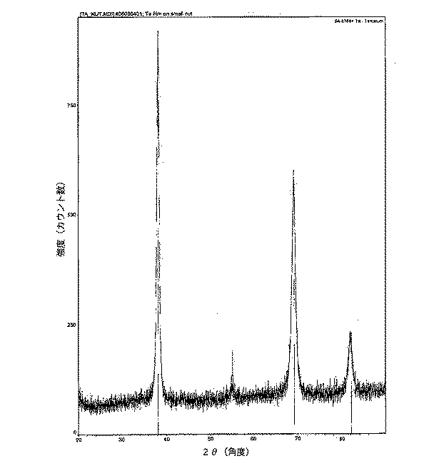
さらに、参照することを以って本明細書の一部とする米国特許出願第11/040,433号に開示されているように、スパッタされるTaは通常、正方格子(β層として知られている)または体心立方(bcc)(α層として知られている)の2種類の結晶層の一方として存在する。Taのα層は、β層よりも大幅に延性が高いため、より大きな歪みに耐えることができる。したがって、本発明には、Taのα層がより好ましい。図6は、コーティングがαタンタルであることを示す、上記した実験5の条件で形成されたコーティングのX線回折パターンである。基材バイアスを用いたKrまたはXe中でのTaスパッタリングでは、α層が堆積されることが当分野で知られている。例えば、「サーフェス・アンド・コーティングス・テクノロジー(Surface and Coatings Technology)146〜147」(2001年、p344〜350)を参照されたい。しかしながら、従来技術または我々の経験では、厚みが10μmのα Taコーティングが、剥離やコーティング欠損が起こることなくステントの使用で生じる極めて大きな歪みに耐えうることを示すものが存在しなかった。また、従来技術は、α Taをこのようなオープンな多孔性構造に堆積できることを示していない。 Further, as disclosed in US patent application Ser. No. 11 / 040,433, which is hereby incorporated by reference, the sputtered Ta is usually a square lattice (known as a β layer). Or one of two types of crystal layers, known as body-centered cubic (bcc) (known as α-layer). Since the Ta α layer is significantly more ductile than the β layer, it can withstand greater strain. Therefore, a Ta α layer is more preferred in the present invention. FIG. 6 is an X-ray diffraction pattern of a coating formed under the conditions of Experiment 5 above, indicating that the coating is alpha tantalum. In Ta sputtering in Kr or Xe using a substrate bias, it is known in the art that an α layer is deposited. For example, see "Surface and Coatings Technology 146-147" (2001, p344-350). However, none of the prior art or our experience has shown that an αTa coating with a thickness of 10 μm can withstand the extremely large strains that occur with the use of a stent without delamination or coating defects. Also, the prior art does not show that αTa can be deposited in such an open porous structure.
オープンな多孔性構造は、他の利点も有する。例えば、コーティング中の微小空洞により、時間経過で徐々に溶出する薬物または他の物質を含めることができる。当分野では、現在、ステントの薬物溶出コーティングは、ポリマー材料を用いて形成されている。多孔性無機コーティングにより、ポリマーのオーバーコートが必要ない薬物溶出ステントを形成できる。 An open porous structure has other advantages. For example, microcavities in the coating can include drugs or other substances that elute gradually over time. Currently in the art, drug eluting coatings on stents are formed using polymeric materials. The porous inorganic coating can form a drug eluting stent that does not require a polymer overcoat.
驚くべきことに、位置Cにおけるステントは全て、条件にかかわらず位置Aおよび位置Bと同じまたはそれ以上の接着性が得られた。表2は、この驚くべき結果を例示している(NAは、その位置でデータが取れなかったコーティング実験を示している)。位置Cにおけるステントは、位置AまたはBのステントの剥落が著しいコーティング条件下でも、常に殆どまたは全く剥落がなかった。表2から分かるように、これが、広範囲のコーティング条件で当てはまる。位置CのステントのAf値は、他の条件の位置CのステントのAf値と同等であり、ACコーティングの場合、位置CのステントのAf値が著しく低いこともあった。約0.45Pa(3.4ミリトル)の圧力、−150Vのバイアスで2kWのAC電力で、Kr中でスパッタコーティングされる位置Cでのステント(実験番号2および3)は、メタリックの外観であり、Af値が38℃〜42℃の範囲である。約0.45Pa(3.4ミリトル)の圧力、2kWのDC電力、−50Vバイアスで、Krを用いて位置Cでコーティングされたステント(実験8)は、ブラックの外観で、Af値がわずか24℃であった。24℃のAf値は、コーティング前のAf値と実質的に変化していない。メタリックおよびブラックのサンプルはともに、優れた接着性を有する。位置Cで実質的に常に好ましい接着性およびAf値が得られるという事実は、予想していなかった。
位置Cのステントは、位置Aまたは位置Bのステントに比べ、全体的により斜めで、より低いコーティングエネルギー束を受ける。斜めのコーティング束とは、堆積する原子の大部分が、コーティングされる表面に対して、ほぼ垂直以外の方向で到達することを意味する。上側および下側のターゲットから位置Cのステントの表面に達する原子の一部は、背景スパッターガス(background sputter gas)との衝突によって著しくエネルギーを損失したり、方向性を失ったりすることなく、コーティング表面に到達する。このような原子は、その殆どが図2および図3に示されているステントに近接したターゲットの部分から来て、斜めのコーティング束を生成する。他の原子は、基材表面に到達する前に、背景ガスと衝突してエネルギーおよび方向性を失う。このような原子は、概ね、離れた位置にあるターゲットの部分から来て、低エネルギーのコーティング束を形成する。エネルギーが背景ガスのエネルギーまで軽減される前に、Ta原子が約0.45Pa(3.4ミリトル)のAr中を移動する平均距離が、約15cm〜30cmであることを、ウエストウッド(Westwood)が計算した(W.D.ウエストウッド(W. D. Westwood)著、「ダイオードスパッタリングシステムにおける堆積速度の計算(Calculation of deposition rates in diode sputtering systems)」、ジャーナル・オブ・バキューム・サイエンス・アンド・テクノロジー(Journal of Vacuum Science and Technology)、第15巻、1978年、p.1)。(この距離は、Kr中ではやや短くなり、正確な値は、Ta原子の初期エネルギーによって異なる。)われわれの円柱ターゲットは、内径が約34cmであるため、ターゲットの平面に配置された基材(位置AおよびB)は、ターゲット間に配置された基材(位置C)よりも、エネルギーの高い多くの垂直入射原子を受け取る。 The stent at position C is generally more diagonal and receives a lower flux of coating energy than the stent at position A or position B. By oblique coating bundles is meant that the majority of the depositing atoms arrive in a direction other than substantially perpendicular to the surface to be coated. Some of the atoms that reach the surface of the stent at position C from the upper and lower targets can be coated without significant energy loss or loss of directionality due to collision with the background sputter gas. Reach the surface. Most of these atoms come from the portion of the target proximate to the stent shown in FIGS. 2 and 3, creating a diagonal coating bundle. Other atoms collide with the background gas and lose energy and direction before reaching the substrate surface. Such atoms generally come from portions of the target that are remotely located to form a low energy coating bundle. Before the energy is reduced to that of the background gas, the average distance that Ta atoms travel in Ar at about 0.45 Pa (3.4 mTorr) is about 15-30 cm. (WD Westwood, "Calculation of deposition rates in diode sputtering systems", Journal of Vacuum Science and Technology (Journal of Vacuum Science and Technology), Vol. 15, 1978, p. 1). (This distance is slightly shorter in Kr, and the exact value depends on the initial energy of Ta atoms.) Since our cylindrical target has an inner diameter of about 34 cm, the substrate ( Positions A and B) receive many more normal incident atoms with higher energy than the substrate (position C) placed between the targets.
図2および図3に示されている円筒型マグネトロンの配置のジオメトリにより、位置Cにおけるステントの表面に到達する原子は、比較的斜めの角度で、あるいは比較的低いエネルギーで到達することを、確実にする。図2および図3を参照すると、ステントがターゲットに近く、到達するTa原子がエネルギーを殆ど失わない場合、原子は斜角で到達する。そして、ステントがチャンバの中心に近く、到達する角度が小さい場合は、ステントがターゲット表面から離れているため、到達するTa原子は、気体との衝突によりエネルギーが失われる。 The geometry of the cylindrical magnetron arrangement shown in FIGS. 2 and 3 ensures that atoms reaching the surface of the stent at position C will arrive at a relatively oblique angle or at a relatively low energy. To. Referring to FIGS. 2 and 3, when the stent is close to the target and the arriving Ta atoms lose little energy, the atoms arrive at an oblique angle. When the stent is close to the center of the chamber and the angle of arrival is small, since the stent is away from the target surface, energy of the reaching Ta atoms is lost due to collision with the gas.
物理蒸着中の原子が、低エネルギーあるいは傾角で基材表面に到達する場合は、概ね垂直の入射角あるいは高エネルギーで到達する原子から形成されるコーティングに比べて、密度の低いコーティングとなることが、当分野で広く知られている。低い基材バイアス(表1の実験5、表2の実験8)で堆積されたDC低電力コーティングのブラックの外観は、コーティングの相当な有孔率の結果であると考えられる。通常は、低密度物理蒸着コーティングは、望ましくないと考えられているが、比較的低密度すなわち多孔性コーティングとなる条件は、本発明に非常に好ましい結果を与えることが分かった。 When the atoms during physical vapor deposition reach the substrate surface with low energy or tilt angle, the coating may have a lower density than coatings formed from atoms that reach almost normal incident angles or high energy. Widely known in the art. The black appearance of the DC low power coating deposited at low substrate bias (Experiment 5 in Table 1, Experiment 8 in Table 2) is believed to be a result of the considerable porosity of the coating. Normally, low density physical vapor deposition coatings are considered undesirable, but conditions that result in relatively low density or porous coatings have been found to give very favorable results to the present invention.
コーティングのジオメトリが重要であるという別の証拠が、以下の実験で確認された。図2および図3に示されている固定具を用いて、位置Cで、約0.45Pa(3.4ミリトル)の圧力、2kWのDC電力、−50Vのバイアスで、Kr中で多数のコーティングを行った。前述したように、ステントを、垂直ロッドを中心に回転させるとともに、ステント自身の垂直軸を中心に回転させた。この方法でコーティングしたステントは、底部はマットブラックであるが、上部は僅かに光沢がある。対照的に、図7に示されているように、ステントの上に第2のプレート24を配置した点を除いて同じ条件下で、ステント22にコーティングを施した場合、ステントは、底部から上部まで均一なブラックとなった。
Additional evidence that the geometry of the coating was important was confirmed in the following experiment. Using the fixture shown in FIGS. 2 and 3, at position C, a number of coatings in Kr at a pressure of about 0.45 Pa (3.4 mTorr), 2 kW DC power, −50 V bias Went. As described above, the stent was rotated about the vertical rod and about the vertical axis of the stent itself. A stent coated in this manner is matte black at the bottom but slightly glossy at the top. In contrast, when the
図2および図3に示されている固定具を用いて位置Cで得られる均一な外観は、コーティング構造が、ステントとスパッターガスとの互いに対する詳細な位置関係に依存することを示唆している。上記したように、ステントが図3に示されている位置C1にある場合、ステントは、近接したターゲットの部分から大きな斜角で物質を受け取り、ターゲットの他の部分から到達するコーティング物質は長い距離移動しなければならない。したがって、全てのコーティング束は、大きな角度で到達するか、またはかなり長い距離を移動して、スパッタリングガスとの衝突でエネルギーおよび方向性を失う。しかしながら、ステントが図3に示されている位置C2にある場合、ステントは、全ての方向からやや小さい角度でコーティングされる。図3に示されている構成では、位置Cにおいて、ステントの下部は、ステントを保持するプレートによって底部のターゲットからのより直接的なエネルギー束から遮蔽されるが、ステントの上部は、上部のターゲットからのより直接的なエネルギー束からステントの下部のようには遮蔽されていない。図7に示されているように、ステントの上方にプレートを設けることにより、ステントの全ての部分において、より直接的なコーティングエネルギー束が遮蔽され、は、比較的大きい入射角か、または背景ガスによって散乱され、エネルギーおよび方向性が失われた後のコーティング物質が到達する。ステントの上方のプレートにより、位置の対称性が得られ、ステントに形成されるコーティングが、全体的に均一なブラックになる。 The uniform appearance obtained at location C using the fixture shown in FIGS. 2 and 3 suggests that the coating structure depends on the detailed positional relationship between the stent and the sputter gas relative to each other. . As described above, when the stent is in the position C1 shown in FIG. 3, the stent receives material at a large bevel from adjacent target portions and the coating material reaching from other portions of the target is a long distance. Must move. Thus, all coating bundles arrive at large angles or travel a relatively long distance and lose energy and directionality upon impact with the sputtering gas. However, when the stent is in position C2 shown in FIG. 3, the stent is coated at a slightly smaller angle from all directions. In the configuration shown in FIG. 3, at position C, the lower portion of the stent is shielded from more direct energy flux from the bottom target by the plate holding the stent, while the upper portion of the stent is shielded from the upper target. It is not shielded from the more direct energy flux from the bottom of the stent. As shown in FIG. 7, by providing a plate above the stent, a more direct coating energy flux is shielded in all parts of the stent, with a relatively high incidence angle or background gas. The coating material arrives after it is scattered by energy and directionality lost. The plate above the stent provides positional symmetry and the coating formed on the stent is a uniform black throughout.
他の方法を用いてチャンバ内の基材の配置および移動を行っても、上記した結果と同様の結果を得ることができ、このような方法は、本発明の範囲内に含まれる。別の実験では、3つのステントを、図8および図9に示されているように配置した。3つ全てのステント22を、チャンバ内のそれぞれの位置に固定し、コーティング実験の際にそれぞれの垂直軸を中心に回転させた。最も内側のステントは、陰極中心線から3cm離間し、中間のステントは、陰極中心線から7cm離間し、最も外側のステントは、陰極中心線から11cm離間させた。堆積は、2kWのDC電力、約0.45Pa(3.4ミリトル)のKr圧力、そして−50Vでステントをバイアスして行った。これらは、表2の実験8に用いた条件と同じである。3つ全てのステントが、マットブラックの外観であり、試験で優れた接着性が確認された。したがって、陰極内の実質的にあらゆる径方向位置に配置され、それぞれの垂直軸を中心に回転されるステントは、ターゲット間に軸方向に配置されれば、満足のいくコーティングが得られる。
Other methods can be used to place and move the substrate in the chamber to achieve results similar to those described above, and such methods are within the scope of the present invention. In another experiment, three stents were placed as shown in FIGS. All three
それ程好ましくはないが、別法として、衝突により到達する原子のエネルギーを低減させるために、基材から離して大きなターゲットを用いるか、または入射コーティングを斜めにする方法があるが、この方法では、スパッタリングガスの圧力が上昇する。 Although less preferred, other methods include using a large target away from the substrate or tilting the incident coating to reduce the energy of the atoms reached by collision, but with this method, The pressure of the sputtering gas increases.
スパッタリングは、ガスが連続的に流れる条件下で行う。すなわち、スパッタリングガスが、一定の速度でチャンバ内に導入され、同じ速度でチャンバから排出されるため、圧力が一定になり、チャンバ内のガスが連続的にパージされる。この流れは、コーティングの際にシステムから発生する蒸気などの不所望の気体を除去するために必要である。このような不所望の気体は、成長するコーティングに混入して、その特性に悪影響を及ぼしうる。 Sputtering is performed under conditions where gas flows continuously. That is, since sputtering gas is introduced into the chamber at a constant rate and exhausted from the chamber at the same rate, the pressure becomes constant and the gas in the chamber is continuously purged. This flow is necessary to remove unwanted gases such as vapor generated from the system during coating. Such unwanted gases can be incorporated into the growing coating and adversely affect its properties.
拡散ポンプ、ターボ分子ポンプ、および低温ポンプなどのスパッタリングに用いる高真空ポンプは、それらの開口部での許容圧力に制限がある。したがって、高いスパッタリング圧力を得るためには、このようなポンプを「絞る」、すなわちチャンバの圧力をポンプの圧力よりも著しく高くする制限をポンプの開口部に配置する必要があることがよく知られている。このような「絞り」は、チャンバ内を通るガスの流れ、すなわちガスの流速が必然的に低下する。驚くべきことに、高いガスの流速で、コーティングの接着性が改善されることを見出した。 High vacuum pumps used for sputtering, such as diffusion pumps, turbomolecular pumps, and cryogenic pumps, have a limited allowable pressure at their openings. Therefore, it is well known that in order to obtain high sputtering pressure, it is necessary to place a restriction at the pump opening that "squeezes" such a pump, ie the pressure of the chamber is significantly higher than the pressure of the pump. ing. Such “throttle” inevitably reduces the flow of gas through the chamber, ie the gas flow rate. Surprisingly, it has been found that at high gas flow rates, the adhesion of the coating is improved.
ある実験では、内径が19cm、長さが10cmの円筒型マグネトロン陰極を用いて、約3.99Pa(30ミリトル)のスパッタリング圧力、Ar中で、Taを用いてステントをコーティングした。この圧力を得るために、真空システムのターボ分子高真空ポンプを絞る必要があった。このコーティングの際のArの流量は、21L/秒の絞られたポンピング速度に一致する約84Pa(0.63トル)‐L/秒とした。ステントは、ターゲット表面から約9cm離して、陰極の中心に配置した。陰極のスパッタリング電力は200Wとした。ウエストウッドの計算によると、熱運動速度に達する前に約3.99Pa(30ミリトル)でAr中を移動するTa原子の平均距離は、その初期エネルギーによって異なるが、1.7cm〜3.4cmの範囲である。したがって、このようなコーティング条件では、極めて密度の低いコーティングが得られるはずである。外観がブラックのコーティングされたステントはこれに当てはまる。しかしながら、コーティングの接着性は、極めて低かった。 In one experiment, a stent was coated with Ta in Ar at a sputtering pressure of about 3.99 Pa (30 mTorr) using a cylindrical magnetron cathode with an inner diameter of 19 cm and a length of 10 cm. In order to obtain this pressure, it was necessary to squeeze the turbomolecular high vacuum pump of the vacuum system. The Ar flow rate during this coating was approximately 84 Pa (0.63 Torr) -L / sec, consistent with a throttled pumping speed of 21 L / sec. The stent was placed in the center of the cathode about 9 cm away from the target surface. The cathode sputtering power was 200 W. According to Westwood's calculations, the average distance of Ta atoms moving in Ar at about 3.99 Pa (30 mtorr) before reaching the thermal motion speed depends on its initial energy, but is between 1.7 cm and 3.4 cm. It is a range. Thus, under such coating conditions, a very low density coating should be obtained. This is the case for coated stents with a black appearance. However, the adhesion of the coating was very low.
別の実験では、図2および図3に示されているように、直径34cmの2つの陰極を用いて、位置Cでステントにコーティングを施した。このスパッタリングガスは、約0.45Pa(3.4ミリトル)の圧力のKrとした。2kWのDC電力、−50Vの基材バイアス、および表2の実験8の条件を用いた。Krの流速は、28cm3/分(標準状態換算)(standard cubic centimeters per minute)、すなわち約48Pa(0.36トル)‐L/秒とした。約0.45Pa(3.4ミリトル)の圧力では、これは、コーティング中の104L/秒の絞られたポンピング速度に一致する。得られたブラックのコーティングは全て、試験すると、レベル1〜3の剥落であった。次いで、ポンプの絞りの位置を変更して、Krの流速を200cm3/分(標準状態換算)、すなわち約337Pa(2.53トル)‐L/秒に増大させた。前回と同じ電力、圧力、およびバイアスレベルで、C位置でステントにコーティングを施した。条件の違いは、このコーティングの際に絞ったポンピング速度を744L/秒とした点だけである。この場合、コーティングを検査すると、剥落や割れがなかった。このような条件下で磨きステンレス鋼表面に設けられたコーティングの表面の走査電子顕微鏡写真を図11に示す。コーティングのオープンな多孔性がはっきりと確認できる。
In another experiment, the stent was coated at location C using two cathodes with a diameter of 34 cm, as shown in FIGS. The sputtering gas was Kr with a pressure of about 0.45 Pa (3.4 mTorr). A 2 kW DC power, a −50 V substrate bias, and the conditions of Experiment 8 in Table 2 were used. The flow rate of Kr was 28 cm 3 / min (standard cubic centimeters per minute), that is, about 48 Pa (0.36 Torr) -L / sec. At a pressure of about 0.45 Pa (3.4 mTorr), this corresponds to a squeezed pumping speed of 104 L / s during coating. All of the resulting black coatings had a
上記した結果から、高いスパッタリング圧力を得る際に通常は必要となる低いガスの流速では、十分な接着性が得られないという結論に達した。スパッタリング圧力とシステムのジオメトリは、コーティング束が、大きな入射角で基材表面に達するか、またはスパッタリング原子がターゲットから十分に離れた距離移動してエネルギーが著しく軽減されてから基材表面に達するように選択しなければならない。 From the above results, it was concluded that sufficient adhesion cannot be obtained at a low gas flow rate, which is normally required when obtaining a high sputtering pressure. Sputtering pressure and system geometry ensure that the coating bundle reaches the substrate surface at a large angle of incidence, or the sputtering atoms travel a distance sufficiently away from the target to significantly reduce energy before reaching the substrate surface. Must be selected.
図示したように、円筒マグネトロンのジオメトリにより、これを十分に達成することができるが、平面状のターゲットを用いても同じ結果を達成できる。平面状のターゲットを用いても同じ結果を達成できる。平面状のターゲットの場合は、ターゲットと基材との距離が十分に離れるように基材をターゲット表面から十分に離す必要がある。別法として、コーティング材料が大きな入射角で到達するように、基材を平面状のターゲットの側方に配置することができる。この構成は、図10に例示されている。もちろん、平面状のターゲット50の場合、図示されているステント22の位置により、コーティング材料が非効率的に使用されることになる。それでも、図10は、円筒型マグネトロン以外のジオメトリを用いて、どのように本発明の方法を使用できるかを例示している。
As shown, the cylindrical magnetron geometry can achieve this well, but the same result can be achieved using a planar target. The same result can be achieved using a planar target. In the case of a planar target, it is necessary to sufficiently separate the substrate from the target surface so that the distance between the target and the substrate is sufficiently separated. Alternatively, the substrate can be placed to the side of the planar target so that the coating material arrives at a large angle of incidence. This configuration is illustrated in FIG. Of course, in the case of a
本発明は、特定の好適な形態を用いてかなり詳細に説明してきたが、他の形態も可能である。例えば、ステント以外の装置を、Taまたは別の放射線不透過性材料でコーティングすることができる。したがって、添付の特許請求の概念および範囲は、ここで開示した好適な形態の説明に限定されるべきものではない。 Although the present invention has been described in considerable detail using certain preferred forms, other forms are possible. For example, devices other than stents can be coated with Ta or another radiopaque material. Accordingly, the concept and scope of the appended claims should not be limited to the description of the preferred form disclosed herein.
添付の特許請求の範囲、要約書、および添付の図面を含む本明細書に開示した全ての特徴、ならびに開示した全ての方法および工程における全てのステップは、少なくとも一部のこのような特徴および/またはステップが相互に排他的である場合の組合せを除き、任意の組合せに組み合わせることができる。添付の特許請求の範囲、要約書、および添付の図面を含む本明細書に開示した全ての特徴は、特段の記載がない限り、同一、同等、または類似の目的を果たす代替の特徴と置換することができる。したがって、特段の記載がない限り、開示した全ての特徴は、一般的な一連の同等または類似の特徴の単なる一例である。 All features disclosed in this specification, including the appended claims, abstract, and accompanying drawings, and all steps in all disclosed methods and processes, are at least part of such features and / or Or it can be combined in any combination except when the steps are mutually exclusive. All features disclosed in this specification, including the appended claims, abstract, and accompanying drawings, are replaced with alternative features serving the same, equivalent, or similar purpose unless otherwise indicated. be able to. Thus, unless expressly stated otherwise, all features disclosed are only examples of a generic series of equivalent or similar features.
特定の機能を果たすための「手段」または特定の機能を果たすための「ステップ」を明確に規定していない特許請求の範囲における全ての要素は、米国特許法第112条に記載されている「手段」または「ステップ」と解釈されるべきものではない。 All elements in the claims that do not expressly define "means" for performing a specific function or "steps" for performing a specific function are described in 35 USC 112. It should not be construed as “means” or “step”.
〔実施の態様〕
(1)医療装置において、
(a)少なくとも部分的に放射線透過性材料を含む本体と、
(b)前記本体の少なくとも一部に設けられた多孔性Taコーティングと、
を含み、
前記Taコーティングが、前記医療装置が放射線不透過性となるように十分な厚みを有し、許容できない剥落が起こることなく、前記医療装置の使用中に生じる歪みに耐えることができる、
医療装置。
(2)実施態様(1)に記載の医療装置において、
前記Taコーティングは、主にbcc結晶相からなる、医療装置。
(3)実施態様(1)に記載の医療装置において、
前記Taコーティングの厚みは、3μm〜10μmの範囲である、医療装置。
(4)実施態様(1)に記載の医療装置において、
前記医療装置は、ステントである、医療装置。
(5)実施態様(1)に記載の医療装置において、
前記医療装置は、ガイドワイヤである、医療装置。
Embodiment
(1) In medical devices,
(A) a body at least partially comprising a radiolucent material;
(B) a porous Ta coating provided on at least a portion of the body;
Including
The Ta coating has sufficient thickness so that the medical device is radiopaque and can withstand distortions that occur during use of the medical device without unacceptable flaking.
Medical device.
(2) In the medical device according to the embodiment (1),
The Ta coating is a medical device mainly composed of a bcc crystal phase.
(3) In the medical device according to the embodiment (1),
The thickness of the said Ta coating is a medical device which is the range of 3 micrometers-10 micrometers.
(4) In the medical device according to the embodiment (1),
The medical device is a stent.
(5) In the medical device according to embodiment (1),
The medical device is a guide wire.
(6)実施態様(1)に記載の医療装置において、
前記医療装置は、腔内装置である、医療装置。
(7)実施態様(1)に記載の医療装置において、
前記Taコーティングは、物理蒸着法によって前記本体に施される、医療装置。
(8)実施態様(7)に記載の医療装置において、
前記物理蒸着法は、スパッタリング、陰極アーク蒸着(cathodic arc deposition)、または熱蒸着(thermal evaporation)からなる群から選択される1つを含む、医療装置。
(9)実施態様(1)に記載の医療装置において、
前記Taコーティング中に、時間とともに溶出する材料、
をさらに含む、医療装置。
(10)医療装置にTa層を堆積させるための方法において、
(a)少なくとも1つのTaスパッタターゲットを含むスパッタコーティングシステムにおいて、不活性ガスの背景圧力(background pressure)を維持するステップと、
(b)前記Taターゲットに電圧を加えて、スパッタリングを起こすステップと、
(c)所定時間スパッタリングして、所望の厚みのコーティングを形成するステップと、
を含み、
前記Ta層が、少なくとも80%の可視スペクトル放射率を有する、
方法。
(6) In the medical device according to the embodiment (1),
The medical device is an intracavitary device.
(7) In the medical device according to the embodiment (1),
The Ta coating is applied to the body by physical vapor deposition.
(8) In the medical device according to embodiment (7),
The physical vapor deposition method includes a medical device including one selected from the group consisting of sputtering, cathodic arc deposition, or thermal evaporation.
(9) In the medical device according to the embodiment (1),
A material that elutes over time during the Ta coating;
A medical device.
(10) In a method for depositing a Ta layer on a medical device,
(A) maintaining a background pressure of inert gas in a sputter coating system comprising at least one Ta sputter target;
(B) applying a voltage to the Ta target to cause sputtering;
(C) sputtering for a predetermined time to form a coating having a desired thickness;
Including
The Ta layer has a visible spectral emissivity of at least 80%;
Method.
(11)実施態様(10)に記載の方法において、
堆積の際の前記医療装置の平衡温度を、前記方法によって間接的に制御する、方法。
(12)実施態様(10)に記載の方法において、
前記平衡温度は、150℃〜450℃の範囲である、方法。
(13)実施態様(10)に記載の方法において、
前記方法の際に、前記医療装置に電圧を加える、方法。
(14)実施態様(13)に記載の方法において、
前記電圧は、第1の時間の間、前記医療装置を予備清浄するための初期高電圧を含む、方法。
(15)実施態様(14)に記載の方法において、
前記初期高電圧は、300V〜500Vの範囲である、方法。
(11) In the method according to embodiment (10),
A method in which the equilibrium temperature of the medical device during deposition is indirectly controlled by the method.
(12) In the method according to embodiment (10),
The method wherein the equilibrium temperature is in the range of 150 ° C to 450 ° C.
(13) In the method according to embodiment (10),
Applying a voltage to the medical device during the method.
(14) In the method according to embodiment (13),
The method wherein the voltage comprises an initial high voltage for precleaning the medical device for a first time.
(15) In the method according to embodiment (14),
The method wherein the initial high voltage ranges from 300V to 500V.
(16)実施態様(14)に記載の方法において、
前記第1の時間は、1分〜20分の範囲である、方法。
(17)実施態様(13)に記載の方法において、
前記電圧は、第2の時間の間加えられる第2の低電圧を含む、方法。
(18)実施態様(17)に記載の方法において、
前記低電圧は、10V〜100Vの範囲である、方法。
(19)実施態様(17)に記載の方法において、
前記第2の時間は、1時間〜5時間の範囲である、方法。
(20)実施態様(10)に記載の方法において、
前記不活性ガスは、Ar、Kr、およびXeを含む群から選択される、方法。
(16) In the method according to embodiment (14),
The method wherein the first time ranges from 1 minute to 20 minutes.
(17) In the method according to embodiment (13),
The method, wherein the voltage comprises a second low voltage applied for a second time.
(18) In the method according to embodiment (17),
The method wherein the low voltage ranges from 10V to 100V.
(19) In the method according to embodiment (17),
The method wherein the second time ranges from 1 hour to 5 hours.
(20) In the method according to embodiment (10),
The method, wherein the inert gas is selected from the group comprising Ar, Kr, and Xe.
(21)実施態様(10)に記載の方法において、
前記電圧は、1μm/時間〜5μm/時間の堆積速度を生み出す、方法。
(22)実施態様(10)に記載の方法において、
前記電圧は、直流である、方法。
(23)実施態様(10)に記載の方法において、
前記電圧は、交流である、方法。
(24)実施態様(10)に記載の方法において、
前記電圧は、パルスで加えられる、方法。
(25)実施態様(10)に記載の方法において、
前記ターゲットは、円筒型である、方法。
(21) In the method according to embodiment (10),
The method wherein the voltage produces a deposition rate of 1 μm / hour to 5 μm / hour.
(22) In the method according to embodiment (10),
The method wherein the voltage is direct current.
(23) In the method according to embodiment (10),
The method wherein the voltage is alternating current.
(24) In the method according to embodiment (10),
The method wherein the voltage is applied in pulses.
(25) In the method according to embodiment (10),
The method wherein the target is cylindrical.
(26)実施態様(10)に記載の方法において、
前記ターゲットは、プレートである、方法。
(27)実施態様(10)に記載の方法において、
前記Ta層は、多孔質である、方法。
(28)実施態様(27)に記載の方法において、
時間とともに溶出する材料を前記Ta層の孔に導入するステップ、
をさらに含む、方法。
(29)医療装置において、
(a)外層を有する本体と、
(b)前記外層の少なくとも一部分に設けられた放射線不透過性コーティングと、
を含み、
前記コーティングが、物理蒸着法によって施される、
医療装置。
(30)医療装置において、
(a)少なくとも部分的に放射線透過性材料を含む本体と、
(b)前記本体の少なくとも一部に設けられたTaコーティングと、
を含み、
前記Taコーティングが、許容できない剥落が起こることなく、前記医療装置の使用中に生じる歪みに耐えることができる、
医療装置。
(26) In the method according to embodiment (10),
The method wherein the target is a plate.
(27) In the method according to embodiment (10),
The method, wherein the Ta layer is porous.
(28) In the method according to embodiment (27),
Introducing a material that elutes over time into the pores of the Ta layer;
Further comprising a method.
(29) In a medical device,
(A) a body having an outer layer;
(B) a radiopaque coating provided on at least a portion of the outer layer;
Including
The coating is applied by physical vapor deposition,
Medical device.
(30) In a medical device,
(A) a body at least partially comprising a radiolucent material;
(B) Ta coating provided on at least a part of the main body;
Including
The Ta coating can withstand distortions that occur during use of the medical device without unacceptable flaking.
Medical device.
Claims (40)
(a)柔軟な本体と、
(b)前記本体の少なくとも一部に設けられた、堆積により多数の柱が形成され柱間に孔が形成され、該柱間の間隔が1nm〜1000nmの範囲にある多孔性円柱状金属コーティングと、
を含み、
前記コーティングが、許容できない剥落を起こすことなく、前記医療装置の使用中に生じる歪みに耐えることができ、
前記コーティングが、少なくとも80%の可視スペクトル放射率を有し、
前記医療装置がガイドワイヤまたはステントである医療装置。In medical devices,
(A) a flexible body;
(B) a porous columnar metal coating provided on at least a part of the main body, wherein a plurality of columns are formed by deposition and holes are formed between the columns, and the interval between the columns is in the range of 1 nm to 1000 nm; ,
Including
The coating can withstand distortions that occur during use of the medical device without causing unacceptable flaking;
Said coating, have a visible spectrum radiation of at least 80%,
A medical device wherein the medical device is a guide wire or a stent .
(a)前記柔軟な本体が、少なくとも部分的に放射線透過性材料を含み、かつ
(b)前記金属コーティングが、Taコーティングを含み、
該Taコーティングが、前記医療装置が放射線不透過性となるように十分な厚みを有し、かつ許容できない剥落を起こすことなく、前記医療装置の使用時の前記本体の屈曲で生じる歪みに耐えることができる、
前記医療装置。The medical device according to claim 1, wherein
(A) the flexible body includes at least partially a radiation transmissive material; and (b) the metal coating includes a Ta coating;
The Ta coating has sufficient thickness so that the medical device is radiopaque and resists strain caused by bending of the body during use of the medical device without causing unacceptable flaking. Can
The medical device.
前記コーティングの厚みは、およそ3μm〜10μmの範囲である、前記医療装置。The medical device according to claim 2,
The medical device, wherein the coating has a thickness in the range of approximately 3 μm to 10 μm.
前記Taコーティングは、物理蒸着法によって前記本体に施されている、前記医療装置。The medical device according to claim 2,
The medical device, wherein the Ta coating is applied to the body by physical vapor deposition.
前記物理蒸着法は、スパッタリング、陰極アーク蒸着(cathodic arc deposition)、または熱蒸着(thermal evaporation)からなる群から選択される1つを含む、前記医療装置。The medical device according to claim 4, wherein
The medical device, wherein the physical vapor deposition method includes one selected from the group consisting of sputtering, cathodic arc deposition, or thermal evaporation.
前記Taコーティング中に、時間とともに溶出する材料、
をさらに含む、前記医療装置。The medical device according to claim 2,
A material that elutes over time during the Ta coating;
The medical device further comprising:
(a)前記本体が、外層を有する弾性保形本体であり、かつ
(b)前記コーティングが、該外層の少なくとも一部分に設けられた放射線不透過性コーティングであり、
該コーティングが、物理蒸着法によって施されている、
前記医療装置。The medical device according to claim 1, wherein
(A) the body is an elastic shaped body having an outer layer, and (b) the coating is a radiopaque coating provided on at least a portion of the outer layer;
The coating is applied by physical vapor deposition,
The medical device.
(a)前記本体が変形可能であり、
(b)前記金属コーティングが、Taコーティングを含む、
前記医療装置。The medical device according to claim 1, wherein
(A) the body is deformable;
(B) the metal coating includes a Ta coating;
The medical device.
前記本体が、超弾性および形状記憶特性を有する材料を、少なくとも部分的に含む弾性保形本体である、
前記医療装置。The medical device according to claim 1, wherein
The body is an elastic shape-retaining body at least partially comprising a material having superelastic and shape memory properties;
The medical device.
前記コーティングが、金、プラチナ、タンタル、およびタングステンからなる群から選択される、前記医療装置。The medical device according to claim 1, wherein
The medical device, wherein the coating is selected from the group consisting of gold, platinum, tantalum, and tungsten.
前記医療装置が生物学的血管内での使用のためのステントである、前記医療装置。The medical device according to claim 9, wherein
The medical device, wherein the medical device is a stent for use in a biological vessel.
前記コーティングが放射線不透過性コーティングである、前記医療装置。The medical device according to claim 9, wherein
The medical device, wherein the coating is a radiopaque coating.
前記本体がニチノールを含む、前記医療装置。The medical device according to claim 9, wherein
The medical device, wherein the body comprises nitinol.
前記孔に薬物が導入される、前記医療装置。The medical device according to claim 1, wherein
The medical device, wherein a drug is introduced into the hole.
前記装置が腔内装置である、前記医療装置。The medical device according to claim 1, wherein
The medical device, wherein the device is an intracavitary device.
前記腔内装置が、ガイドワイヤまたはステントである、前記医療装置。The medical device according to claim 15,
The intraluminal device is a gas guide wire or stent, the medical device.
前記装置が、移植後、時間とともに溶出する材料を前記コーティング中にさらに含む移植可能な装置である、前記医療装置。The medical device according to claim 1, wherein
The medical device, wherein the device is an implantable device further comprising a material in the coating that elutes over time after implantation.
前記腔内装置がステントである、前記医療装置。The medical device according to claim 16,
The medical device, wherein the intraluminal device is a stent.
前記本体がニチノールを含む、前記医療装置。The medical device according to claim 2,
The medical device, wherein the body comprises nitinol.
前記装置がステントである、前記医療装置。The medical device according to claim 2,
The medical device, wherein the device is a stent.
(a)少なくとも1つのTaスパッタターゲットを含むスパッタコーティングシステムにおいて、不活性ガスの背景圧力を維持するステップと、
(b)前記Taターゲットに電圧を加えて、スパッタリングを起こすステップと、
(c)所定時間スパッタリングして、所望の厚みの、堆積により多数の柱が形成された多孔性円柱状金属コーティングを形成するステップと、からなり、
前記コーティングが、少なくとも80%の可視スペクトル放射率を有するTa層である、
前記方法。 In a method of depositing a Ta layer on a medical device that is a guidewire or stent ,
(A) maintaining a background pressure of an inert gas in a sputter coating system comprising at least one Ta sputter target;
(B) applying a voltage to the Ta target to cause sputtering;
(C) sputtering for a predetermined time to form a porous cylindrical metal coating having a desired thickness and having a number of pillars formed by deposition,
The coating is a Ta layer having a visible spectral emissivity of at least 80%;
Said method.
堆積の際の前記医療装置の平衡温度を、前記方法によって間接的に制御する、前記方法。The method of claim 21, wherein
The method wherein the equilibrium temperature of the medical device during deposition is indirectly controlled by the method.
前記平衡温度は、150℃〜450℃の範囲である、前記方法。The method of claim 21, wherein
The method, wherein the equilibrium temperature ranges from 150 ° C to 450 ° C.
前記方法の際に、前記医療装置に電圧を加える、前記方法。The method of claim 21, wherein
The method wherein a voltage is applied to the medical device during the method.
前記電圧が初期高電圧を含み、第1の時間の間、前記医療装置を予備清浄する、前記方法。25. The method of claim 24, wherein
The method, wherein the voltage includes an initial high voltage and the medical device is precleaned for a first time.
前記初期高電圧は、300V〜500Vの範囲である、前記方法。26. The method of claim 25, wherein
The method, wherein the initial high voltage ranges from 300V to 500V.
前記第1の時間は、1分〜20分の範囲である、前記方法。26. The method of claim 25, wherein
The method, wherein the first time ranges from 1 minute to 20 minutes.
前記電圧は、第2の時間の間加えられる第2の低電圧を含む、前記方法。25. The method of claim 24, wherein
The method, wherein the voltage comprises a second low voltage applied for a second time.
前記低電圧は、10V〜100Vの範囲である、前記方法。The method of claim 28, wherein
The method, wherein the low voltage ranges from 10V to 100V.
前記第2の時間が、1時間〜5時間の範囲である、前記方法。The method of claim 28, wherein
The method, wherein the second time ranges from 1 hour to 5 hours.
前記不活性ガスは、Ar、Kr、およびXeを含む群から選択される、前記方法。The method of claim 21, wherein
The method, wherein the inert gas is selected from the group comprising Ar, Kr, and Xe.
前記電圧は、1μm/時間〜5μm/時間の堆積速度を生み出す、前記方法。The method of claim 21, wherein
The method, wherein the voltage produces a deposition rate of 1 μm / hour to 5 μm / hour.
前記電圧は、直流である、前記方法。The method of claim 21, wherein
The method, wherein the voltage is direct current.
前記電圧は、交流である、前記方法。The method of claim 21, wherein
The method, wherein the voltage is alternating current.
前記電圧は、パルスで加えられる、前記方法。The method of claim 21, wherein
The method, wherein the voltage is applied in pulses.
前記ターゲットは、円筒型である、前記方法。The method of claim 21, wherein
The method, wherein the target is cylindrical.
前記ターゲットは、プレートである、前記方法。The method of claim 21, wherein
The method, wherein the target is a plate.
前記Ta層は、多孔質である、前記方法。The method of claim 21, wherein
The method, wherein the Ta layer is porous.
時間とともに溶出する材料を前記Ta層の孔に導入するステップ、
をさらに含む、前記方法。40. The method of claim 38, wherein
Introducing a material that elutes over time into the pores of the Ta layer;
The method further comprising:
(a)少なくとも1つの金属スパッタターゲットを含むスパッタコーティングシステムにおいて、不活性ガスの背景圧力を維持するステップと、
(b)前記金属ターゲットに電圧を加えて、スパッタリングを起こすステップと、
(c)前記装置上に所定時間スパッタリングして、所望の厚みの、堆積により多数の柱が形成され柱間に孔が形成され、該柱間の間隔が1nm〜1000nmの範囲にある多孔性円柱状金属コーティングを形成するステップと、からなり、
前記コーティングが、少なくとも80%の可視スペクトル放射率を有する、
前記方法。 In a method of depositing a metal layer on an implantable and flexible shape retaining medical device that is a guidewire or stent ,
(A) maintaining a background pressure of an inert gas in a sputter coating system comprising at least one metal sputter target;
(B) applying a voltage to the metal target to cause sputtering;
(C) Sputtering on the apparatus for a predetermined time, a porous circle having a desired thickness, a large number of columns formed by deposition, and pores are formed between the columns, and the interval between the columns is in the range of 1 nm to 1000 nm. Forming a columnar metal coating, and
The coating has a visible spectral emissivity of at least 80%;
Said method.
Applications Claiming Priority (4)
| Application Number | Priority Date | Filing Date | Title |
|---|---|---|---|
| US55572104P | 2004-03-23 | 2004-03-23 | |
| US57957704P | 2004-06-14 | 2004-06-14 | |
| US11/040,433 US20050165472A1 (en) | 2004-01-22 | 2005-01-21 | Radiopaque coating for biomedical devices |
| PCT/US2005/009651 WO2005094486A2 (en) | 2004-03-23 | 2005-03-23 | Radiopaque coating for biomedical devices |
Publications (3)
| Publication Number | Publication Date |
|---|---|
| JP2008502373A JP2008502373A (en) | 2008-01-31 |
| JP2008502373A5 JP2008502373A5 (en) | 2008-05-08 |
| JP4620109B2 true JP4620109B2 (en) | 2011-01-26 |
Family
ID=35064387
Family Applications (1)
| Application Number | Title | Priority Date | Filing Date |
|---|---|---|---|
| JP2007505130A Expired - Fee Related JP4620109B2 (en) | 2004-03-23 | 2005-03-23 | Radiopaque coatings for biomedical devices |
Country Status (4)
| Country | Link |
|---|---|
| EP (1) | EP1791667A4 (en) |
| JP (1) | JP4620109B2 (en) |
| CA (1) | CA2560232C (en) |
| WO (1) | WO2005094486A2 (en) |
Cited By (1)
| Publication number | Priority date | Publication date | Assignee | Title |
|---|---|---|---|---|
| US8002822B2 (en) | 2004-01-22 | 2011-08-23 | Isoflux, Inc. | Radiopaque coating for biomedical devices |
Families Citing this family (6)
| Publication number | Priority date | Publication date | Assignee | Title |
|---|---|---|---|---|
| US8231926B2 (en) | 2007-12-21 | 2012-07-31 | Innovatech, Llc | Marked precoated medical device and method of manufacturing same |
| US7714217B2 (en) | 2007-12-21 | 2010-05-11 | Innovatech, Llc | Marked precoated strings and method of manufacturing same |
| US8900652B1 (en) | 2011-03-14 | 2014-12-02 | Innovatech, Llc | Marked fluoropolymer surfaces and method of manufacturing same |
| EP2996580B1 (en) * | 2013-04-11 | 2020-02-12 | Balt Usa Llc | Radiopaque devices for cerebral aneurysm repair |
| JP6152026B2 (en) * | 2013-09-24 | 2017-06-21 | テルモ株式会社 | Coating apparatus and stent manufacturing method |
| CN113235061B (en) * | 2021-05-18 | 2022-08-05 | 南昌大学第一附属医院 | Preparation process of tantalum metal coating of medical screw |
Family Cites Families (16)
| Publication number | Priority date | Publication date | Assignee | Title |
|---|---|---|---|---|
| US5607463A (en) * | 1993-03-30 | 1997-03-04 | Medtronic, Inc. | Intravascular medical device |
| DE19506188C2 (en) * | 1995-02-22 | 2003-03-06 | Miladin Lazarov | Implant and its use |
| JPH08224310A (en) * | 1995-02-22 | 1996-09-03 | Olympus Optical Co Ltd | Baloon catheter |
| US5607442A (en) * | 1995-11-13 | 1997-03-04 | Isostent, Inc. | Stent with improved radiopacity and appearance characteristics |
| US5922020A (en) * | 1996-08-02 | 1999-07-13 | Localmed, Inc. | Tubular prosthesis having improved expansion and imaging characteristics |
| US6174329B1 (en) * | 1996-08-22 | 2001-01-16 | Advanced Cardiovascular Systems, Inc. | Protective coating for a stent with intermediate radiopaque coating |
| US5843172A (en) * | 1997-04-15 | 1998-12-01 | Advanced Cardiovascular Systems, Inc. | Porous medicated stent |
| CN1310647A (en) * | 1998-01-19 | 2001-08-29 | 迈德奎斯特产品公司 | Method and apparatus for providing a conductive, amorphous non-stick coating |
| US6849085B2 (en) * | 1999-11-19 | 2005-02-01 | Advanced Bio Prosthetic Surfaces, Ltd. | Self-supporting laminated films, structural materials and medical devices manufactured therefrom and method of making same |
| US6799076B2 (en) * | 1999-12-07 | 2004-09-28 | Greatbatch-Hittman, Inc. | Coated electrode and method of making a coated electrode |
| JP2001190688A (en) * | 2000-01-07 | 2001-07-17 | Yuichi Mori | Stent |
| JP2003135588A (en) * | 2001-11-08 | 2003-05-13 | Univ Nihon | Percutaneous transluminal drug delivery device |
| US6638301B1 (en) * | 2002-10-02 | 2003-10-28 | Scimed Life Systems, Inc. | Medical device with radiopacity |
| JP2004276131A (en) * | 2003-03-12 | 2004-10-07 | Ckd Corp | Vacuum chuck |
| US7488343B2 (en) * | 2003-09-16 | 2009-02-10 | Boston Scientific Scimed, Inc. | Medical devices |
| JP2007518528A (en) * | 2004-01-22 | 2007-07-12 | イソフラックス・インコーポレイテッド | Radiopaque coatings for biomedical devices |
-
2005
- 2005-03-23 EP EP05726079A patent/EP1791667A4/en not_active Withdrawn
- 2005-03-23 WO PCT/US2005/009651 patent/WO2005094486A2/en not_active Application Discontinuation
- 2005-03-23 JP JP2007505130A patent/JP4620109B2/en not_active Expired - Fee Related
- 2005-03-23 CA CA2560232A patent/CA2560232C/en not_active Expired - Fee Related
Cited By (1)
| Publication number | Priority date | Publication date | Assignee | Title |
|---|---|---|---|---|
| US8002822B2 (en) | 2004-01-22 | 2011-08-23 | Isoflux, Inc. | Radiopaque coating for biomedical devices |
Also Published As
| Publication number | Publication date |
|---|---|
| CA2560232C (en) | 2013-07-16 |
| WO2005094486A2 (en) | 2005-10-13 |
| EP1791667A2 (en) | 2007-06-06 |
| CA2560232A1 (en) | 2005-10-13 |
| WO2005094486A3 (en) | 2007-11-29 |
| EP1791667A4 (en) | 2011-08-17 |
| JP2008502373A (en) | 2008-01-31 |
Similar Documents
| Publication | Publication Date | Title |
|---|---|---|
| JP5060946B2 (en) | Radiopaque coatings for biomedical devices | |
| US20050288773A1 (en) | Radiopaque coating for biomedical devices | |
| US20050165472A1 (en) | Radiopaque coating for biomedical devices | |
| JP4620109B2 (en) | Radiopaque coatings for biomedical devices | |
| US20200107946A1 (en) | Guidewires and thin film catheter-sheaths and method of making same | |
| JP4995420B2 (en) | High strength vacuum deposited Nitinol alloy film, medical thin film graft material, and method of making same. | |
| US7402173B2 (en) | Metal stent with surface layer of noble metal oxide and method of fabrication | |
| US20130238081A1 (en) | Molybdenum Endoprostheses | |
| KR101791337B1 (en) | A method for preparing nitinol-based radiopaque stent by deposition of heavy metal via selective plasma etching | |
| JP2009513206A (en) | Method for manufacturing a coated endovascular device | |
| US20070106374A1 (en) | Radiopaque coating for biomedical devices | |
| JP2011184803A (en) | Radiopaque coating for biomedical device | |
| WO2024050118A1 (en) | Improved radiopacity in implantable medical devices | |
| MX2008005406A (en) | A method for production of a coated endovascular device |
Legal Events
| Date | Code | Title | Description |
|---|---|---|---|
| RD04 | Notification of resignation of power of attorney |
Free format text: JAPANESE INTERMEDIATE CODE: A7424 Effective date: 20071205 |
|
| RD04 | Notification of resignation of power of attorney |
Free format text: JAPANESE INTERMEDIATE CODE: A7424 Effective date: 20080131 |
|
| RD03 | Notification of appointment of power of attorney |
Free format text: JAPANESE INTERMEDIATE CODE: A7423 Effective date: 20080222 |
|
| A521 | Written amendment |
Free format text: JAPANESE INTERMEDIATE CODE: A523 Effective date: 20080226 |
|
| A621 | Written request for application examination |
Free format text: JAPANESE INTERMEDIATE CODE: A621 Effective date: 20080226 |
|
| A871 | Explanation of circumstances concerning accelerated examination |
Free format text: JAPANESE INTERMEDIATE CODE: A871 Effective date: 20080226 |
|
| A521 | Written amendment |
Free format text: JAPANESE INTERMEDIATE CODE: A821 Effective date: 20080222 |
|
| RD04 | Notification of resignation of power of attorney |
Free format text: JAPANESE INTERMEDIATE CODE: A7424 Effective date: 20080222 |
|
| A975 | Report on accelerated examination |
Free format text: JAPANESE INTERMEDIATE CODE: A971005 Effective date: 20080418 |
|
| A131 | Notification of reasons for refusal |
Free format text: JAPANESE INTERMEDIATE CODE: A131 Effective date: 20080527 |
|
| A601 | Written request for extension of time |
Free format text: JAPANESE INTERMEDIATE CODE: A601 Effective date: 20080820 |
|
| A602 | Written permission of extension of time |
Free format text: JAPANESE INTERMEDIATE CODE: A602 Effective date: 20080827 |
|
| RD04 | Notification of resignation of power of attorney |
Free format text: JAPANESE INTERMEDIATE CODE: A7424 Effective date: 20081017 |
|
| A521 | Written amendment |
Free format text: JAPANESE INTERMEDIATE CODE: A523 Effective date: 20081126 |
|
| A131 | Notification of reasons for refusal |
Free format text: JAPANESE INTERMEDIATE CODE: A131 Effective date: 20090210 |
|
| A601 | Written request for extension of time |
Free format text: JAPANESE INTERMEDIATE CODE: A601 Effective date: 20090501 |
|
| A602 | Written permission of extension of time |
Free format text: JAPANESE INTERMEDIATE CODE: A602 Effective date: 20090513 |
|
| A02 | Decision of refusal |
Free format text: JAPANESE INTERMEDIATE CODE: A02 Effective date: 20090930 |
|
| A521 | Written amendment |
Free format text: JAPANESE INTERMEDIATE CODE: A523 Effective date: 20100129 |
|
| A911 | Transfer of reconsideration by examiner before appeal (zenchi) |
Free format text: JAPANESE INTERMEDIATE CODE: A911 Effective date: 20100210 |
|
| A131 | Notification of reasons for refusal |
Free format text: JAPANESE INTERMEDIATE CODE: A131 Effective date: 20100601 |
|
| A521 | Written amendment |
Free format text: JAPANESE INTERMEDIATE CODE: A523 Effective date: 20100830 |
|
| TRDD | Decision of grant or rejection written | ||
| A01 | Written decision to grant a patent or to grant a registration (utility model) |
Free format text: JAPANESE INTERMEDIATE CODE: A01 Effective date: 20101012 |
|
| A01 | Written decision to grant a patent or to grant a registration (utility model) |
Free format text: JAPANESE INTERMEDIATE CODE: A01 |
|
| A61 | First payment of annual fees (during grant procedure) |
Free format text: JAPANESE INTERMEDIATE CODE: A61 Effective date: 20101027 |
|
| FPAY | Renewal fee payment (event date is renewal date of database) |
Free format text: PAYMENT UNTIL: 20131105 Year of fee payment: 3 |
|
| R150 | Certificate of patent or registration of utility model |
Ref document number: 4620109 Country of ref document: JP Free format text: JAPANESE INTERMEDIATE CODE: R150 Free format text: JAPANESE INTERMEDIATE CODE: R150 |
|
| R250 | Receipt of annual fees |
Free format text: JAPANESE INTERMEDIATE CODE: R250 |
|
| R250 | Receipt of annual fees |
Free format text: JAPANESE INTERMEDIATE CODE: R250 |
|
| R250 | Receipt of annual fees |
Free format text: JAPANESE INTERMEDIATE CODE: R250 |
|
| R250 | Receipt of annual fees |
Free format text: JAPANESE INTERMEDIATE CODE: R250 |
|
| R250 | Receipt of annual fees |
Free format text: JAPANESE INTERMEDIATE CODE: R250 |
|
| R250 | Receipt of annual fees |
Free format text: JAPANESE INTERMEDIATE CODE: R250 |
|
| R250 | Receipt of annual fees |
Free format text: JAPANESE INTERMEDIATE CODE: R250 |
|
| LAPS | Cancellation because of no payment of annual fees |