JP4618552B2 - Ultraviolet optical device and light source device - Google Patents
Ultraviolet optical device and light source device Download PDFInfo
- Publication number
- JP4618552B2 JP4618552B2 JP2005121096A JP2005121096A JP4618552B2 JP 4618552 B2 JP4618552 B2 JP 4618552B2 JP 2005121096 A JP2005121096 A JP 2005121096A JP 2005121096 A JP2005121096 A JP 2005121096A JP 4618552 B2 JP4618552 B2 JP 4618552B2
- Authority
- JP
- Japan
- Prior art keywords
- window member
- ultraviolet
- light
- silicon dioxide
- optical
- Prior art date
- Legal status (The legal status is an assumption and is not a legal conclusion. Google has not performed a legal analysis and makes no representation as to the accuracy of the status listed.)
- Expired - Lifetime
Links
Images


Landscapes
- Exposure Of Semiconductors, Excluding Electron Or Ion Beam Exposure (AREA)
- Exposure And Positioning Against Photoresist Photosensitive Materials (AREA)
Description
本発明は、紫外光(特に、深紫外光)を用いた光学装置に関するもので、例えば、半導体検査装置の照明光学系、半導体露光装置の照明光学系等に適用できる紫外光学装置に関する。 The present invention relates to an optical apparatus using ultraviolet light (particularly deep ultraviolet light), and relates to an ultraviolet optical apparatus applicable to, for example, an illumination optical system of a semiconductor inspection apparatus and an illumination optical system of a semiconductor exposure apparatus.
半導体素子を製造するフォトリソグラフィ工程では、フォトマスクのパターンを投影光学系を介して基板上に露光する縮小投影露光装置や、形成された回路を撮像光学系により撮像して検査する光学検査装置が使用されている。このような露光装置や検査装置に用いられる光源は、半導体集積回路の微細化に伴って短波長化が進んでおり、近年ではエキシマレーザ等の深紫外(DUV)光源が広く使用されている。 In a photolithography process for manufacturing a semiconductor element, there is a reduction projection exposure apparatus that exposes a photomask pattern onto a substrate via a projection optical system, and an optical inspection apparatus that images and inspects a formed circuit with an imaging optical system. in use. Light sources used in such exposure apparatuses and inspection apparatuses have been shortened in wavelength with the miniaturization of semiconductor integrated circuits, and in recent years, deep ultraviolet (DUV) light sources such as excimer lasers have been widely used.
深紫外光が空気中を浮遊している化学物質に照射されるとこの化学物質が活性化され、上記の露光装置や検査装置における光学系を構成するガラス部品の表面に析出付着することが知られている。特に、装置内の雰囲気中に含まれる有機珪素系ガスは深紫外光の照射を受けて酸素と反応し、ガラス部品の表面に二酸化珪素(SiO2)として析出してガラス部品の表面に曇りを生じさせ、光学系の照度低下、照度むらを発生させることが従来から知られている。 It is known that when deep UV light irradiates a chemical substance floating in the air, this chemical substance is activated and deposited on the surface of the glass component that constitutes the optical system in the above exposure apparatus and inspection apparatus. It has been. In particular, the organosilicon gas contained in the atmosphere in the apparatus reacts with oxygen upon irradiation with deep ultraviolet light, and deposits as silicon dioxide (SiO 2 ) on the surface of the glass component, causing cloudiness on the surface of the glass component. It has been conventionally known to cause this to cause a decrease in illuminance and uneven illuminance of the optical system.
このようなことから、従来では、光学系全体、もしくは光学系の主要部品を気密状態に構成されたチャンバー(容器)内に配設するとともに、このチャンバーの内部を窒素等の不活性ガスで充満する等してケミカルクリーンな状態とし、このようなガラス部品の表面の曇りの発生を防止することが知られている。例えば、特許文献1には光学系全体をチャンバー内に配設する例が開示されており、特許文献2には光学系の主要部品をチャンバー内に配設する例が開示されている。なお、光学系の主要部品をチャンバー内に配設する場合には、紫外光源はチャンバー外に設けられ、紫外光源から出射された紫外光束はチャンバーに設けられた窓部材を通して内部に配設された主要光学系部品に入射し、且つ主要光学系部品からの出射光(透過光、反射光等)は窓部材を介して外部に出射される。このため、窓部材はチャンバー内への空気の流入を防止できるようにチャンバー壁に一体に設けられ、且つ紫外光束を通過させる材料から作られる。
ところで、光学系全体をチャンバー内に配設する場合には、光学系の大きさに応じたチャンバー容積が必要であり、上述の半導体露光装置や光学検査装置のような大型の光学系をチャンバー内に入れるにはチャンバーが大きくなりすぎて実用上その製作が難しいという問題がある。 By the way, when the entire optical system is disposed in the chamber, a chamber volume corresponding to the size of the optical system is required, and a large optical system such as the above-described semiconductor exposure apparatus or optical inspection apparatus is disposed in the chamber. There is a problem that the chamber becomes too large to be put into the chamber, making it difficult to manufacture practically.
一方、主要光学系部品のみをチャンバー内に配設する構成の場合、窓部材の外面は外気に触れるため、外面に二酸化珪素(SiO2)が析出するのを避けることができない。特に、通常は窓部材の表面には反射防止膜が形成されているが、この反射防止膜の表面に二酸化珪素膜が析出すると反射防止膜の光学特性が変化し、窓部材の光透過率(紫外光透過率)が変化(低下)するという問題がある。特に、光透過率特性の変化が波長毎に相違する、すなわち、分光透過率の変化特性が波長毎に相違するという問題がある。このように光透過率特性が変化すると、光学装置としての性能が変化するため、二酸化珪素膜の析出に応じて光透過率特性が大きく変化する前に窓部材を交換する必要があり、窓部材を比較的短時間で交換しなければならないという問題があった。 On the other hand, in the configuration in which only the main optical system components are arranged in the chamber, the outer surface of the window member is exposed to the outside air, so that it is inevitable that silicon dioxide (SiO 2 ) is deposited on the outer surface. In particular, an antireflection film is usually formed on the surface of the window member. However, when a silicon dioxide film is deposited on the surface of the antireflection film, the optical characteristics of the antireflection film change, and the light transmittance ( There is a problem that the ultraviolet light transmittance) changes (decreases). In particular, there is a problem that the change in the light transmittance characteristic is different for each wavelength, that is, the change characteristic of the spectral transmittance is different for each wavelength. When the light transmittance characteristic changes in this way, the performance as an optical device changes. Therefore, it is necessary to replace the window member before the light transmittance characteristic changes greatly according to the deposition of the silicon dioxide film. There was a problem that it had to be replaced in a relatively short time.
本発明はこのような問題に鑑みたもので、窓部材の外面に二酸化珪素膜が析出した場合でも光透過率(紫外光透過率)の変化(低下)が小さく、且つ分光透過率の特性変化の波長毎の相違も小さくなる窓部材を有し、窓部材を交換することなく長期間の使用が可能となるような紫外光学装置を提供することを目的とする。 The present invention has been made in view of such problems. Even when a silicon dioxide film is deposited on the outer surface of the window member, the change (decrease) in light transmittance (ultraviolet light transmittance) is small, and the spectral transmittance characteristics change. It is an object of the present invention to provide an ultraviolet optical device that has a window member in which the difference for each wavelength becomes small and can be used for a long time without replacing the window member.
このようなことから本発明の紫外光学装置は、紫外線を透過させる窓部材を有した容器と、前記容器内に配設された光学系とを備え、前記窓部材を介して外部空間から前記光学系に紫外光を入射させ、前記光学系から前記窓部材を介して前記外部空間へ前記紫外線を出射させるように構成され、前記窓部材は二酸化珪素を主成分とする材料から作られるとともに、前記外部空間に露出している前記窓部材の外面は、コーティングを施すことなく前記二酸化珪素を露出して形成される。 Ultraviolet optical device of the present invention from such things, a container having a window member for transmitting ultraviolet light, and an optical system disposed in the container, outer space or al ago through said window member serial to incident ultraviolet light into the optical system, the is configured to emit the ultraviolet to the external space through the optical system or al before Kimado member, said window member is mainly composed of silicon dioxide material together made from the outer surface of the window member that is exposed to the external space is formed by exposing the Ku before Symbol silicon dioxide such be coated.
そして、例えば容器の内部が不活性ガスで満たされるなどして、容器の内部がケミカルクリーンな状態に保持されているのが好ましい。また、窓部材の内面に反射防止膜が形成されているのが好ましい。なお、本発明の紫外光学装置は、紫外光として深紫外光を用いる場合に適している。
And it is preferable that the inside of the container is kept in a chemically clean state, for example, by filling the inside of the container with an inert gas. Further, it is preferable that an antireflection film is formed on the inner surface of the window member. The ultraviolet optical device of the present invention is suitable when deep ultraviolet light is used as ultraviolet light.
一方、本発明に係る光源装置は、紫外線を照射する光源と、前記紫外線を透過させる窓部材を有した容器と、前記光源の最も近くに位置し、前記容器内に配設された光学系とを備え、前記窓部材を介して外部空間から前記光学系に紫外光を入射させ、前記光学系から前記窓部材を介して前記外部空間へ前記紫外線を出射させるように構成され、前記窓部材は二酸化珪素を主成分とする材料から作られるとともに、前記外部空間に露出している前記窓部材の外面は、コーティングを施すことなく前記二酸化珪素を露出して形成される。
On the other hand, a light source device according to the present invention includes a light source that irradiates ultraviolet light, a container having a window member that transmits the ultraviolet light, and an optical system that is positioned closest to the light source and disposed in the container. wherein the window member is incident ultraviolet light from the outside space into the optical system through, it is constructed from the optical system so as to emit the ultraviolet to the external space through the window member, the window member The outer surface of the window member which is made of a material mainly composed of silicon dioxide and exposed to the external space is formed by exposing the silicon dioxide without coating .
このような本発明の紫外光学装置によれば、窓部材の外面はコーティングを施すことなく無垢の二酸化珪素(SiO2)が露出して形成されているので、この外面に二酸化珪素(SiO2)が析出したとしても同一材料の層が形成されるだけであり、窓部材の光学的性能、特に光透過率の変化(低下)が小さく、且つ分光透過率特性の分光毎の変化の相違も小さく押さえられる。この結果、長時間の使用においても窓部材を交換する必要がなくなり、紫外光学装置を、部品交換やメンテナンスを行なわなくても光学性能を低下させることなく長時間使用することが可能となる。 According to the ultraviolet optical device of the present invention, since the outer surface of the window member is solid silicon dioxide (SiO 2) are formed by exposed without a coating, the silicon dioxide to the outer surface (SiO 2) Is deposited, the layer of the same material is only formed, and the optical performance of the window member, in particular, the change (decrease) in light transmittance is small, and the difference in change in spectral transmittance characteristics for each spectrum is also small. Pressed. As a result, it is not necessary to replace the window member even when used for a long time, and the ultraviolet optical device can be used for a long time without deteriorating the optical performance without replacement of parts or maintenance.
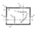
以下、図面を参照して本発明の最適な実施形態について説明する。まず、図1に本発明の紫外光学装置の第1の実施形態を示している。この装置は、気密性を有するチャンバー(容器)10の内部に、レンズ30,ビームスプリッタ40、フィルタ50といった主要光学部材を配設して構成されている。なお、これら主要光学部材を通って延びる光軸上に位置して第1〜第3窓部材20,21,22が、チャンバー10の壁15に形成された開口に気密状態を保つように接合配設されている。このため、チャンバー10の内部空間Bは、壁15の開口部に第1〜第3窓部材20,21,22を一体に有して構成されたチャンバー10により気密状態に保たれて外部空間Aから隔離されている。
DESCRIPTION OF EXEMPLARY EMBODIMENTS Hereinafter, exemplary embodiments of the invention will be described with reference to the drawings. First, FIG. 1 shows a first embodiment of the ultraviolet optical apparatus of the present invention. This apparatus is configured by disposing main optical members such as a lens 30, a
この光学装置においては、図示しない紫外光源から矢印を有した一点鎖線で示す方向(矢印の方向)に紫外光(波長が約400nm以下の光)、特に深紫外光(波長が約300nm以下の光)が照射される。このため、外部空間Aに設けられた図示しない紫外光源から出射された深紫外光は、まず第1窓部材20を透過してレンズ30に入射してこれを透過し、ビームスプリッタ40により図中上方に反射される光と右方に透過される光とに分けられて、それぞれ第2窓部材21および第3窓部材22を透過して外部空間Aに出射される。
In this optical apparatus, ultraviolet light (light having a wavelength of about 400 nm or less), particularly deep ultraviolet light (light having a wavelength of about 300 nm or less) in a direction (in the direction of the arrow) indicated by an alternate long and short dash line with an arrow from an unillustrated ultraviolet light source. ) Is irradiated. For this reason, deep ultraviolet light emitted from an ultraviolet light source (not shown) provided in the external space A first passes through the
チャンバー10の内部空間Bは、有機珪素系ガスの発生源となる媒質を用いない、いわゆるケミカルクリーンな状態に保たれている。このため、第1窓部材20を透過した深紫外光がチャンバー10の内部空間B内を通過するときに二酸化珪素(SiO2)が析出することがなく、チャンバー10内に配設された主要光学部品(すなわち、レンズ30,ビームスプリッタ40、フィルタ50)の表面に二酸化珪素(SiO2)の層が析出形成することがない。
The internal space B of the chamber 10 is maintained in a so-called chemical clean state in which a medium that is an organic silicon-based gas generation source is not used. For this reason, when the deep ultraviolet light transmitted through the
第1〜第3窓部材20,21,22を代表して、第1窓部材20およびその周囲を拡大して図2に示している。この図から分かるように、第1窓部材20は壁15の開口16に気密接合されて配設されている。第1窓部材20は合成石英(SiO2)から作られた平行平板ガラスからなり、外部空間Aに露出する外面20aと、内部空間Bに露出する内面20bとを有し、外面20aはコーティングを施すことなく無垢の二酸化珪素(SiO2)が露出して形成されている。上述のように内部空間Bの内部はケミカルクリーンな状態に保たれているので、第1窓部材20の内面20bに二酸化珪素(SiO2)の層が析出形成されることがない。これは、第2および第3窓部材21,22についても同様である。
As representative of the first to
しかしながら、第1窓部材20の外面20aは外部空間Aに露出しており、深紫外光束が外部空間Aを通過するときに外部空間A中に含まれる有機珪素系ガスが深紫外光の照射を受けて酸素と反応し、外面20aに二酸化珪素(SiO2)の層が析出形成される。ところが、第1窓部材20の外面20aはコーティングを施すことなく無垢の二酸化珪素(SiO2)が露出しているため、外面20aに二酸化珪素(SiO2)の層が析出形成されても、第1窓部材20が外面20aにおいて僅かに厚みを増すだけのことであり、第1窓部材20の光学特性、特に紫外光透過特性はほとんど変化することがない。当然ながら、分光透過率の特性変化が分光毎に相違することもない。このことは、第2および第3窓部材21,22についても同様である。
However, the outer surface 20a of the
このため、第1〜第3窓部材20,21,22を長時間使用しても光学性能の変化が小さく、この紫外光学装置を、部品交換やメンテナンスを行なわなくても光学性能を低下させることなく長時間使用することが可能である。
For this reason, even if the 1st-
ここで、この実施形態の第1窓部材20を用いた場合と、従来のように第1窓部材20の外面20aに反射防止膜を形成した場合とで、外面20aに二酸化珪素(SiO2)の層が析出形成されたときにおける紫外光透過特性の変化をシミュレーションした結果を図3および図4を参照して説明する。
Here, when the
まず、図3には従来の構成、すなわち外面に反射防止膜を施した窓部材を用いた場合での波長毎の光透過率を示している。この窓部材では、外面の二酸化珪素(SiO2)の層が析出形成されていないときには、反射防止膜により反射が押さえられて波長約250〜400nmの紫外光の全ての波長領域において高い透過率を有している。この図3には、外面に1000nmの二酸化珪素(SiO2)の層が析出形成された場合と、5000nmの二酸化珪素(SiO2)の層が析出形成された場合とを示しており、図示のように二酸化珪素(SiO2)の層が析出形成されると光透過率が大きく変化する。特に、波長毎の光透過率特性、すなわち分光透過率特性の変化が分光波長毎に大きく相違している。 First, FIG. 3 shows the light transmittance for each wavelength in the conventional configuration, that is, when a window member having an antireflection film on the outer surface is used. In this window member, when the outer layer of silicon dioxide (SiO 2 ) is not deposited, reflection is suppressed by the antireflection film, and high transmittance is obtained in all wavelength regions of ultraviolet light having a wavelength of about 250 to 400 nm. Have. FIG. 3 shows a case where a 1000 nm silicon dioxide (SiO 2 ) layer is deposited on the outer surface and a case where a 5000 nm silicon dioxide (SiO 2 ) layer is deposited. As described above, when the silicon dioxide (SiO 2 ) layer is deposited, the light transmittance changes greatly. In particular, the light transmittance characteristic for each wavelength, that is, the change in the spectral transmittance characteristic is greatly different for each spectral wavelength.
このように外面に反射防止膜を有した窓部材を用いると、外面に二酸化珪素(SiO2)の層が析出形成されるに従って光透過率特性が大きく変化(低下)し、且つ分光透過率特性の変化が分光波長毎に大きく相違することになり、紫外光学装置の光学特性が変化するため、窓部材を短時間で交換する必要がある。 When the window member having the antireflection film on the outer surface is used as described above, the light transmittance characteristic is greatly changed (decreased) as the silicon dioxide (SiO 2 ) layer is deposited on the outer surface, and the spectral transmittance characteristic is obtained. Changes greatly for each spectral wavelength, and the optical characteristics of the ultraviolet optical device change. Therefore, it is necessary to replace the window member in a short time.
一方、図4には本発明の構成、すなわち外面に反射防止膜等のコーティングを施すことなく無垢の二酸化珪素(SiO2)を露出させて構成した窓部材を用いた場合での波長毎の光透過率を示している。この窓部材では、外面の二酸化珪素(SiO2)の層が析出形成されていないときには、反射防止膜が無いため光学透過率は上記従来の窓部材より若干(数%)低いが、波長約250〜400nmの深紫外光の全ての波長領域においてほぼ一定の高い透過率を有している。この図4にも、外面に1000nmの二酸化珪素(SiO2)の層が析出形成された場合と、5000nmの二酸化珪素(SiO2)の層が析出形成された場合とを示しており、図示のように二酸化珪素(SiO2)の層が析出形成されても光透過率の変化は小さく、分光透過率特性の変化も小さい。このため、本発明の窓部材を用いれば、これを長時間使用しても光学性能の変化(低下)が小さく、紫外光学装置を、部品交換やメンテナンスを行なわなくても光学性能を低下させることなく長時間使用することが可能である。 On the other hand, FIG. 4 shows the light of each wavelength in the case of using the window member constituted by exposing the solid silicon dioxide (SiO 2 ) without coating the outer surface with an antireflection film or the like. The transmittance is shown. In this window member, when an outer surface silicon dioxide (SiO 2 ) layer is not deposited, the optical transmittance is slightly (several percent) lower than the conventional window member because there is no antireflection film, but the wavelength is about 250. It has a substantially constant high transmittance in all wavelength regions of deep ultraviolet light of ˜400 nm. FIG. 4 also shows a case where a 1000 nm silicon dioxide (SiO 2 ) layer is deposited on the outer surface and a case where a 5000 nm silicon dioxide (SiO 2 ) layer is deposited. Thus, even if the silicon dioxide (SiO 2 ) layer is deposited, the change in light transmittance is small and the change in spectral transmittance characteristics is also small. For this reason, if the window member of the present invention is used, even if it is used for a long time, the change (decrease) in optical performance is small, and the optical performance of the ultraviolet optical device is lowered without replacement of parts or maintenance. And can be used for a long time.
なお、図1および図2に示す紫外光学装置において、第1〜第3窓部材20,21,22の内面(内部空間Bに露出する面)には、二酸化珪素(SiO2)の層が析出形成されることがないため、反射防止膜を形成することが望ましい。内面に反射防止膜を施したときの反射率は1%程度であるのに対して、反射防止膜を施さない無垢の状態での反射率は4%程度であり、約3%程度の光量アップを図ることができる。
In the ultraviolet optical device shown in FIG. 1 and FIG. 2, a silicon dioxide (SiO 2 ) layer is deposited on the inner surfaces (surfaces exposed to the internal space B) of the first to
また、本実施形態においては、チャンバー10の内部空間Bは有機珪素系ガスの発生源となる媒質を用いないケミカルクリーンな状態に保たれているが、チャンバー10内に窒素ガス、ヘリウムガス等の不活性ガスを充満させてケミカルクリーンな状態を作り出しても良い。この場合、チャンバー内部に不活性ガスをリーク無しに完全に閉じこめておくことは難しいため、チャンバー内部のガス置換率をセンサによりモニタリングし、随時不活性ガスを補充供給する装置を設ける必要がある。 Further, in this embodiment, the internal space B of the chamber 10 is kept in a chemically clean state without using a medium serving as a generation source of the organosilicon gas. However, nitrogen gas, helium gas, or the like is contained in the chamber 10. A chemical clean state may be created by filling with an inert gas. In this case, since it is difficult to completely keep the inert gas inside the chamber without leakage, it is necessary to provide a device for monitoring the gas replacement rate inside the chamber with a sensor and supplementing the inert gas as needed.
次に、本発明の第2の実施形態について、図5〜図7を参照して説明する。この実施形態は、本発明に係る紫外光学装置をウエハ外観検査装置に適用した場合の形態である。まず、図5にウエハ外観検査装置の全体構成を示す模式図を示している。この検査装置は、検査対象であるウエハWを載置するウエハ載置台220と、検査用の光を作り出す光源装置100と、この光源装置からの光を導いて先端部205から出射させる光ファイバ200と、先端部205から放射された光を受けるとともにこれを平行光束として反射させて載置台220上に載置されたウエハWの上に照射させる第1ミラー210と、ウエハWに照射されて出てくる反射光もしくは回折光を受けるとともにこれを集光させて反射させる第2ミラー211と、第2ミラー211から反射されてくる光を集光する集光レンズ230と、集光レンズ230により集光された光を受けてウエハWの表面の像を撮像するCCDカメラ240と、CCDカメラ240からの画像信号を受けてウエハWの表面の撮像画像からウエハWの良否を判定する画像処理装置250とを有して構成される。
Next, a second embodiment of the present invention will be described with reference to FIGS. In this embodiment, the ultraviolet optical apparatus according to the present invention is applied to a wafer appearance inspection apparatus. First, FIG. 5 is a schematic diagram showing the overall configuration of the wafer appearance inspection apparatus. The inspection apparatus includes a wafer mounting table 220 on which a wafer W to be inspected is mounted, a
この検査装置を構成する光源装置100の内部の光学系の構成を図6に示している。光源装置100は光源としての水銀ランプ160を有し、水銀ランプ160から発光する広帯域波長の光束は、チャンバー110内にレンズ130を配設して構成される光学装置に入射する。この光学装置を図7に拡大して示しており、断面上において直交する2辺の壁に設けられた第1および第2窓部材120,121と、斜辺となる壁に設けられたダイクロイックミラー140とを一体に有したチャンバー110内にレンズ130が配設されて構成されている。
FIG. 6 shows the configuration of the optical system inside the
水銀ランプ160からの光束は第1窓部材120を通ってレンズ130に照射され、レンズ130により平行光束とされて第1ダイクロイックミラー140に照射される。第1ダイクロイックミラー140は紫外光を反射し、可視光を透過させるように構成されており、可視光はダイクロイックミラー140を透過してそのまま外部に出射され、紫外光は第1ダイクロイックミラー140において反射されて第2窓部材121を通って外部に出射される。
The light beam from the
第1ダイクロイックミラー140を透過して外部に出射された可視光はその光軸上に配設された第1全反射ミラー180により反射された後、所望の輝線スペクトルのみを通過させる第1波長選択フィルタ151を通過して波長選択がなされるとともに第2ダイクロイックミラー141に入射される。第1ダイクロイックミラー140も紫外光を反射し、可視光を透過させるように構成されており、第2ダイクロイックミラー141に入射した可視光はNDフィルタ190を通過して光量調整された後、レンズ131により光ファイバ200の入射端面に集光される。
Visible light transmitted through the first
一方、ダイクロイックミラー140において反射されて第2窓部材121を通って外部に出射された紫外光は、その光軸上に配設された所望の輝線スペクトルのみを通過させる第2波長選択フィルタ150を通過して波長選択が行われた後、第2全反射ミラー181により反射されるとともに第2ダイクロイックミラー141により反射され、さらにNDフィルタ190を通過して光量調整された後、レンズ131により光ファイバ200の入射端面に集光される。
On the other hand, the ultraviolet light reflected by the
なお、第1反射ミラー180と第1波長選択フィルタ151との間に可視光の光路を開閉する第1シャッター171が設けられ、第2窓部材121と第2波長選択フィルタ150との間に紫外光の光路を開閉する第2シャッター170が設けられており、これらシャッター171,170は連動し、いずれか一方のみの光路を開放するようになっている。このため、シャッター171,170により可視光および紫外光を選択的に光ファイバ200の入射端面に集光させることができる。
A
以上のように構成した第2の実施形態に係るウエハ外観検査装置においては、装置内部において水銀ランプ160に最も近く位置して特に強い紫外光の照射を受けるレンズ130をチャンバー110内に配置し、且つ紫外光を反射させる第1ダイクロイックミラー140をチャンバー110の壁に一体に配設してその反射面をチャンバー110の内部空間に露出させている。チャンバー110の内部空間は有機珪素系ガスの発生源となる媒質を用いない構成としたり、窒素ガスを充満させたりしてケミカルクリーンな状態に保たれており、チャンバー110内での二酸化珪素(SiO2)の析出形成が起きないようになっている。
In the wafer visual inspection apparatus according to the second embodiment configured as described above, a
この結果、レンズ130の表面への二酸化珪素(SiO2)の析出が防止でき、第1および第2窓部材120,121の内面への二酸化珪素(SiO2)の析出が防止でき、これらの光透過効率の変化を抑制できる。第1および第2窓部材120,121は合成石英(SiO2)から作られた平行平板ガラスからなり、その外面はコーティングを施すことなく無垢の二酸化珪素(SiO2)が露出して形成されている。この場合、第1実施形態で説明したように、外部空間に含まれる有機珪素系ガスが深紫外光の照射を受けて酸素と反応し、外面に二酸化珪素(SiO2)の層が析出形成されるが、外面はコーティングを施すことなく無垢の二酸化珪素(SiO2)が露出しているため、外面に二酸化珪素(SiO2)の層が析出形成されても、第1および第2窓部材120,121が外面において僅かに厚みを増すだけのことであり、その光学特性、特に紫外光透過特性はほとんど変化することがなく、分光透過率の特性変化が分光毎に相違することもない。なお、第1および第2窓部材120,121の内面には反射防止膜を形成するのが好ましい。
As a result, deposition of silicon dioxide on the surface of the lens 130 (SiO 2) can be prevented, it is possible to prevent deposition of silicon dioxide on the inner surfaces of the first and
また、第1ダイクロイックミラー140は窓部材を兼用する構成であるが、紫外光を反射する内面はケミカルクリーンな状態であり、内面に二酸化珪素(SiO2)の層が析出形成されることはない。一方、外部雰囲気に露出する外面からは可視光が透過して出射する構成であり、この外面に二酸化珪素(SiO2)の層が析出形成されることは少ない。また、第1ダイクロイックミラー140は主成分を二酸化珪素(SiO2)とする基板を用いており、内面に紫外光を反射し可視光を透過させる多層膜コーティングを施しているが外面には無垢の二酸化珪素(SiO2)が露出している。このため、外面に二酸化珪素(SiO2)の層が析出形成されても、その光学的特性、特に光透過率が変化することは少ない。
Further, the first
10 チャンバー(容器)
20,21,22 第1〜第3窓部材
30 レンズ(主要光学部材)
40 ビームスプリッタ(主要光学部材)
50 フィルタ(主要光学部材)
10 Chamber (container)
20, 21, 22 First to third window members 30 Lens (main optical member)
40 Beam splitter (main optical member)
50 filters (main optical members)
Claims (5)
前記窓部材を介して外部空間から前記光学系に紫外光を入射させ、前記光学系から前記窓部材を介して前記外部空間へ前記紫外線を出射させるように構成された紫外光学装置であって、
前記窓部材は二酸化珪素を主成分とする材料から作られるとともに、前記外部空間に露出している前記窓部材の外面は、コーティングを施すことなく前記二酸化珪素を露出させて構成したことを特徴とする紫外光学装置。 A container having a window member that transmits ultraviolet light, and an optical system disposed in the container,
It said window member is incident ultraviolet light from the outside space into the optical system through the optical system or al before configured ultraviolet optical device so as to emit the ultraviolet to the external space through the Kimado member Because
The window member is made of a material mainly composed of silicon dioxide, and the outer surface of the window member exposed to the external space is configured to expose the silicon dioxide without coating. UV optical device.
前記紫外線を透過させる窓部材を有した容器と、
前記光源の最も近くに位置し、前記容器内に配設された光学系とを備え、
前記窓部材を介して外部空間から前記光学系に紫外光を入射させ、前記光学系から前記窓部材を介して前記外部空間へ前記紫外線を出射させるように構成された光源装置であって、
前記窓部材は二酸化珪素を主成分とする材料から作られるとともに、前記外部空間に露出している前記窓部材の外面は、コーティングを施すことなく前記二酸化珪素を露出させて構成したことを特徴とする光源装置。 A light source that emits ultraviolet rays;
A container having a window member that transmits ultraviolet rays;
An optical system located closest to the light source and disposed in the container;
In the light source device is incident ultraviolet light, configured to emit the ultraviolet to the external space through the optical system or al before Kimado member to the optical system from the external space through said window member There,
The window member is made of a material mainly composed of silicon dioxide, and the outer surface of the window member exposed to the external space is configured to expose the silicon dioxide without coating. Light source device.
Priority Applications (1)
| Application Number | Priority Date | Filing Date | Title |
|---|---|---|---|
| JP2005121096A JP4618552B2 (en) | 2005-04-19 | 2005-04-19 | Ultraviolet optical device and light source device |
Applications Claiming Priority (1)
| Application Number | Priority Date | Filing Date | Title |
|---|---|---|---|
| JP2005121096A JP4618552B2 (en) | 2005-04-19 | 2005-04-19 | Ultraviolet optical device and light source device |
Publications (3)
| Publication Number | Publication Date |
|---|---|
| JP2006303094A JP2006303094A (en) | 2006-11-02 |
| JP2006303094A5 JP2006303094A5 (en) | 2008-04-03 |
| JP4618552B2 true JP4618552B2 (en) | 2011-01-26 |
Family
ID=37471047
Family Applications (1)
| Application Number | Title | Priority Date | Filing Date |
|---|---|---|---|
| JP2005121096A Expired - Lifetime JP4618552B2 (en) | 2005-04-19 | 2005-04-19 | Ultraviolet optical device and light source device |
Country Status (1)
| Country | Link |
|---|---|
| JP (1) | JP4618552B2 (en) |
Families Citing this family (2)
| Publication number | Priority date | Publication date | Assignee | Title |
|---|---|---|---|---|
| JP5765504B1 (en) * | 2013-09-13 | 2015-08-19 | ウシオ電機株式会社 | Light irradiation device |
| CN112768341B (en) * | 2021-01-27 | 2025-07-01 | 北京华泰诺安探测技术有限公司 | A multi-window ultraviolet lamp and preparation method thereof |
Family Cites Families (5)
| Publication number | Priority date | Publication date | Assignee | Title |
|---|---|---|---|---|
| JPH083447B2 (en) * | 1987-05-27 | 1996-01-17 | 工業技術院長 | Optical measuring device |
| JPH0729804A (en) * | 1993-07-14 | 1995-01-31 | Canon Inc | Light source device and ultraviolet irradiation device including the light source device |
| JPH1154852A (en) * | 1997-08-06 | 1999-02-26 | Nikon Corp | Optical device for ultraviolet laser |
| JP2001281050A (en) * | 2000-03-30 | 2001-10-10 | Canon Inc | Photodetector, exposure apparatus, device manufacturing method, semiconductor manufacturing factory, and exposure apparatus maintenance method |
| JP4004895B2 (en) * | 2002-08-29 | 2007-11-07 | 株式会社フジクラ | Optical device |
-
2005
- 2005-04-19 JP JP2005121096A patent/JP4618552B2/en not_active Expired - Lifetime
Also Published As
| Publication number | Publication date |
|---|---|
| JP2006303094A (en) | 2006-11-02 |
Similar Documents
| Publication | Publication Date | Title |
|---|---|---|
| TWI833005B (en) | System for use in semiconductor manufacturing and method of fabricating an optical component | |
| JP4026943B2 (en) | Exposure apparatus and device manufacturing method | |
| KR20140019378A (en) | Euv actinic reticle inspection system using imaging sensor with thin film spectral purity filter coating | |
| JP2004289118A (en) | Optical device used for lithography suitable for manufacturing semiconductor devices, and optical lithography | |
| KR101714264B1 (en) | Mask pellicle indicator for haze prevention | |
| WO1999005710A1 (en) | Projection aligner, projection exposure method, optical cleaning method and method of fabricating semiconductor device | |
| JPH07122477A (en) | Lighting optics | |
| TW201925929A (en) | Extreme ultraviolet light source purification equipment | |
| JP4618552B2 (en) | Ultraviolet optical device and light source device | |
| JP4451793B2 (en) | Optical element, lithographic apparatus and device manufacturing method comprising such an optical element | |
| CN110800175A (en) | wavelength conversion device | |
| JP2010272677A (en) | Optical element, exposure apparatus and device manufacturing method | |
| JP7792451B2 (en) | Method and measuring device for inspecting a photomask and an EUV camera - Patent Application 20070122997 | |
| JPH07273016A (en) | Illumination device and projection exposure apparatus using the same | |
| JP2005308896A (en) | Photomask and management method thereof | |
| CN1459124A (en) | Exposure system, exposure method, and production method for device | |
| TW201925906A (en) | Method of fabricating photomask | |
| TWI606310B (en) | A filter, method of formation thereof, and an image sensor | |
| JP2003163159A (en) | Purge gas supply method, exposure apparatus, and device manufacturing method | |
| WO2003036695A1 (en) | Method for feeding purge gas to exposure apparatus, exposure apparatus, and method for manufacturing device | |
| JP2021124690A (en) | Optical equipment, article manufacturing method and optical member manufacturing method | |
| JP4321163B2 (en) | Exposure master, exposure master inspection method and exposure method | |
| JP2007121452A (en) | Method for manufacturing glass substrate for mask blank, method for manufacturing mask blank, method for manufacturing exposure mask, and method for manufacturing glass member for lithography | |
| JPH11354409A (en) | Illumination device, projection exposure apparatus having the same, and method of manufacturing semiconductor device | |
| JP2010251142A (en) | Light irradiation apparatus and inspection device |
Legal Events
| Date | Code | Title | Description |
|---|---|---|---|
| A621 | Written request for application examination |
Free format text: JAPANESE INTERMEDIATE CODE: A621 Effective date: 20080212 |
|
| A521 | Request for written amendment filed |
Free format text: JAPANESE INTERMEDIATE CODE: A523 Effective date: 20080220 |
|
| A977 | Report on retrieval |
Free format text: JAPANESE INTERMEDIATE CODE: A971007 Effective date: 20100611 |
|
| A131 | Notification of reasons for refusal |
Free format text: JAPANESE INTERMEDIATE CODE: A131 Effective date: 20100618 |
|
| A521 | Request for written amendment filed |
Free format text: JAPANESE INTERMEDIATE CODE: A523 Effective date: 20100811 |
|
| TRDD | Decision of grant or rejection written | ||
| A01 | Written decision to grant a patent or to grant a registration (utility model) |
Free format text: JAPANESE INTERMEDIATE CODE: A01 Effective date: 20101001 |
|
| A01 | Written decision to grant a patent or to grant a registration (utility model) |
Free format text: JAPANESE INTERMEDIATE CODE: A01 |
|
| A61 | First payment of annual fees (during grant procedure) |
Free format text: JAPANESE INTERMEDIATE CODE: A61 Effective date: 20101014 |
|
| FPAY | Renewal fee payment (event date is renewal date of database) |
Free format text: PAYMENT UNTIL: 20131105 Year of fee payment: 3 |
|
| R150 | Certificate of patent or registration of utility model |
Ref document number: 4618552 Country of ref document: JP Free format text: JAPANESE INTERMEDIATE CODE: R150 Free format text: JAPANESE INTERMEDIATE CODE: R150 |
|
| FPAY | Renewal fee payment (event date is renewal date of database) |
Free format text: PAYMENT UNTIL: 20131105 Year of fee payment: 3 |
|
| R250 | Receipt of annual fees |
Free format text: JAPANESE INTERMEDIATE CODE: R250 |
|
| R250 | Receipt of annual fees |
Free format text: JAPANESE INTERMEDIATE CODE: R250 |
|
| R250 | Receipt of annual fees |
Free format text: JAPANESE INTERMEDIATE CODE: R250 |
|
| R250 | Receipt of annual fees |
Free format text: JAPANESE INTERMEDIATE CODE: R250 |
|
| R250 | Receipt of annual fees |
Free format text: JAPANESE INTERMEDIATE CODE: R250 |
|
| R250 | Receipt of annual fees |
Free format text: JAPANESE INTERMEDIATE CODE: R250 |
|
| R250 | Receipt of annual fees |
Free format text: JAPANESE INTERMEDIATE CODE: R250 |
|
| R250 | Receipt of annual fees |
Free format text: JAPANESE INTERMEDIATE CODE: R250 |
|
| R250 | Receipt of annual fees |
Free format text: JAPANESE INTERMEDIATE CODE: R250 |
|
| R250 | Receipt of annual fees |
Free format text: JAPANESE INTERMEDIATE CODE: R250 |
|
| R250 | Receipt of annual fees |
Free format text: JAPANESE INTERMEDIATE CODE: R250 |
|
| R250 | Receipt of annual fees |
Free format text: JAPANESE INTERMEDIATE CODE: R250 |
|
| EXPY | Cancellation because of completion of term |