JP4617552B2 - Infusion container and lyophilized drug storage method - Google Patents
Infusion container and lyophilized drug storage method Download PDFInfo
- Publication number
- JP4617552B2 JP4617552B2 JP2000290446A JP2000290446A JP4617552B2 JP 4617552 B2 JP4617552 B2 JP 4617552B2 JP 2000290446 A JP2000290446 A JP 2000290446A JP 2000290446 A JP2000290446 A JP 2000290446A JP 4617552 B2 JP4617552 B2 JP 4617552B2
- Authority
- JP
- Japan
- Prior art keywords
- container
- storage chamber
- drug
- small container
- freeze
- Prior art date
- Legal status (The legal status is an assumption and is not a legal conclusion. Google has not performed a legal analysis and makes no representation as to the accuracy of the status listed.)
- Expired - Fee Related
Links
Images


Landscapes
- Medical Preparation Storing Or Oral Administration Devices (AREA)
Description
【0001】
【発明の属する技術分野】
この発明は、輸液用容器及びその凍結乾燥薬剤収納方法に関し、さらに詳しくは、凍結乾燥薬剤と、その溶解液とを分離した状態で保存しておき、使用直前に容器内で凍結乾燥薬剤と溶解液とを無菌的に混合し、輸液として供給するための輸液用容器及びその輸液溶容器への凍結乾燥薬剤の収納方法に関する。
【0002】
【従来の技術及び発明が解決しようとする課題】
この種の輸液用容器に凍結乾燥薬剤を収納する場合には、予め多量の薬剤を適宜凍結乾燥し、その凍結乾燥後の薬剤から所定量(一容器単位相当量)を小分けして輸液用容器の薬剤収納室に投入するか、例えば、特許第2551881号、第2767016号のごとく、予め特定の小容器を用いて所定量の薬剤を凍結乾燥し、凍結乾燥後、その小容器から凍結乾燥された薬剤を取り出し輸液用容器の薬剤収納室に投入していた。
しかし、凍結乾燥後、粉砕したり、粉砕した凍結乾燥薬剤を所定量計量して輸液用容器に充填するという一連の工程に非常に手間がかかり、一方、小容器を用いる場合には、特に凍結乾燥薬剤を小容器特に凍結乾燥薬剤を小容器から取り出すのに手間がかかるのに加えて小容器に高価な凍結乾燥薬剤が残留してロスが生じる恐れがあるという問題があった。
【0003】
そこで、この発明の主要な目的の1つは、凍結乾燥薬剤を輸液用容器の薬剤収納室に簡便に収納できる輸液用容器を提供することである。
この発明の主要な目的のもう1つは、凍結乾燥用小容器で凍結乾燥した薬剤を残留によるロスなく輸液用容器の薬剤収納室に収納できる輸液用容器を提供することである。
【0004】
【課題を解決するための手段】
この発明は、薬剤を収納する薬剤収納室と、溶解液を収納し前記薬剤収納室に連設された溶解液収納室とを備え、前記薬剤収納室が、口部分を開放し凍結乾燥された薬剤を収容した小容器を収納し、かつ前記溶解液収納室とは保存時には区画され、使用時には連通可能に構成されたことを特徴とする輸液用容器を提供する。
【0005】
すなわち、この発明は、薬剤収納室に、口部分を開放し凍結乾燥された薬剤を収容する小容器を収納することによって、小容器内で予め凍結乾燥された薬剤をそのまま小容器ごと薬剤収納室に収納でき、それによってわざわざ薬剤凍結乾燥用小容器から薬剤を取り出す必要がなく、薬剤の収納工程が極めて容易になり、更にそれによって残留による薬剤のロスをなくすことができる。
【0006】
ここで、薬剤凍結乾燥用小容器は、薬剤を溶解した液の状態(凍結乾燥前の状態)で0.5〜4.0ミリリットル程度収納できると共に、口部分を開放して薬剤の凍結乾燥及び溶解液の通過を可能にし、かつ輸液用容器の薬剤収納室内に収納できる小さな容器状であることが必要で(例えば、口部分の面積:2〜3cm2*高さ:1.0〜1.5cm)、更にこの小容器は、輸液用容器の薬剤収納室内に位置決めできることが好ましい。この小容器を薬剤収納室に位置決めする手段としては、薬剤収納室内に小容器の一部に係止する係止部を設けることであり、この係止部の具体例としては、小容器の側壁に縦溝及び/又は底壁に凹溝をそれぞれ形成し、これらの縦溝及び/又は凹溝に係止するように薬剤収納室の容器本体に突状部、具体例として突部及び/又は突条をそれぞれ形成することを挙げることができる。
なお、この小容器は、上述のとおり、口部分を開放しているが、この口部分に、溶解液を通過させるための開口部を有する蓋を具備してもよい。
また、この小容器は、ポリエチレン、ポリプロピレン、ポリ塩化ビニル、環状ポリオレフィンなどの合成樹脂又はアルミニウム、ステンレス鋼などの金属で構成され、好ましくはポリエチレン、ポリプロピレン又は環状ポリオレフィンで構成される。
【0007】
この発明の輸液用容器の薬剤収納室に、小容器ごと収納される凍結乾燥薬剤としては、具体的には、次の活性成分を例示できる。
抗生剤としては、セファゾリンナトリウム、セフチゾキシムナトリウム、塩酸セフォチアム、塩酸セフメノキシム、セファセトリルナトリウム、セファマンドールナトリウム、セファロリジン、セファタキシムナトリウム、セフォテタンナトリウム、セフォペラゾンナトリウム、セフスロジンナトリウム、セフテゾールナトリウム、セフピラミドナトリウム、セフメタゾールナトリウム、セフロキシナトリウム、硫酸セフォクレスなどのセフェム系抗生物質、またアンピシリンナトリウム、カルベニシリンナトリウム、スルベニシリンナトリウム、チカルシリンナトリウムなどのペニシリン系抗生物質、さらには塩酸バンコマイシンなどがある。抗腫瘍剤としては、マイトマイシンC、フルオロウラシル、テガフール、シタラビンなどがある。抗潰瘍剤としては、ファモチジン、塩酸ラニチジン、シメチジンなどがある。
【0008】
この発明の輸液用容器の溶解液収納室に収納される溶解液としては、生理的食塩水、ブドウ糖液または、システイン、トリプトファンなどを添加したアミノ酸液などが挙げられるが、特にこれらに限定されるものではない。
この発明において、キャップ部材は、具体的には例えば、刺通可能な栓体と、任意にこの栓体に被着される蓋部とからなる。
【0009】
この発明の好ましい態様によれば、薬剤収納室の口部を密封するキャップ部材の上部に(具体例としては上述の蓋部の上に)薬剤変質防止剤収納室を形成し、内部に薬剤変質防止剤として乾燥剤及び/又は脱酸素剤を収納できるよう構成してもよい。乾燥剤は、湿気により変性する薬剤の安定化を目的とするもので、シリカゲル、ゼオライトなどを成分とするものが挙げられる。また、脱酸素剤は、易酸化性を有する薬剤の変性を防止するもので、活性酸化鉄、アモルファス銅などを用いたものが挙げられる。乾燥剤及び脱酸素剤は、薬剤収納室に収納される薬剤の種類などに応じて適宜使用され、それぞれ単独であるいは両者を同時に用いてもよい。
【0010】
この発明における溶解液収納室は、ポリエチレン、ポリプロピレン、ポリ塩化ビニルなどの比較的柔らかい合成樹脂のシートを融着して袋状に成形されるか、これらの合成樹脂をブロー成形した可撓性の容器であることが好ましい。上述の薬剤収納室も、一例としてこのような可撓性の容器とし、両容器を一体に形成してもよい(ダブルバッグ方式)。
【0011】
この発明は、別の観点によれば、小さな容器状で、その側壁及び/又は底壁に、輸液用容器の薬剤収納室内に係止して容器自体を薬剤収納室に位置決めするための縦溝及び/又は凹溝を有する薬剤凍結乾燥用小容器を提供する。
この発明は、更に別の観点によれば、薬剤を収納する薬剤収納室と、溶解液を収納し、内部を前記薬剤収納室の内部と使用時に連通可能に区画され、前記薬剤収納室に連設された溶解液収納室とからなる輸液用容器の前記薬剤収納室に薬剤を収納するに際して、口部分が開放された小容器に薬剤を溶解した液を充填し、常法により凍結乾燥した後、凍結乾燥された薬剤を前記小容器から取り出さずに前記小容器ごと前記薬剤収納室に収納することを特徴とする輸液用容器の凍結乾燥薬剤収納方法を提供する。
【0012】
【発明の実施の形態】
以下、図面に示す実施の形態に基づいてこの発明を詳述する。なお、これによってこの発明が限定されるものではない。
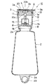
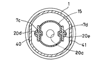
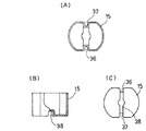
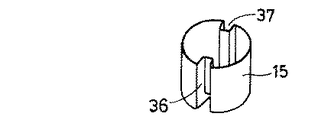
図1はこの発明に係る輸液用容器の実施の形態を示す縦断面図、図2は図1とは90°異なる方向の縦断面図、図3は図2のA−A断面図、図4は主として連通孔の開放状態を説明する一部分解斜視図、図5は図1の薬剤凍結乾燥用小容器を示し、(A)は平面図、(B)は一部縦断面図、(C)は底面図である。図6は、図5の薬剤凍結乾燥用小容器の斜視図である。
さて、図1及び2に示す輸液用容器10は、凍結乾燥薬剤(図示省略)を収納した薬剤収納室1と、溶解液(図示省略)を収納した溶解液収納室2とから主として構成されている。
【0013】
薬剤収納室1は、広口の容器状で、その底部を溶解液収納室2に連設された容器本体8と、この容器本体内に収納された薬剤凍結乾燥用小容器15及びこの小容器内で予め凍結乾燥され、そのまま収納されている凍結乾燥薬剤と、キャップ部材3とからなる。そして容器本体8は、その上端部には、キャップ部材3を装着可能な口部1aを有し、底部6には後述する連通孔5を有し、全体がポリプロピレンで一体に成型され、溶解液収納室2に比較して剛性を大きくされている。
【0014】
溶解液収納室2は、透明なポリプロピレンにより液密で偏平な袋状(厚み:0.2〜0.5mm)にブロー成形され、十分な可撓性と弾力性を有している。溶解液収納室2の上部には、薬剤収納室1の下端部に形成されたポート1bに連接するフランジ状の口部2bが形成されている。溶解液収納室2の下端の縁部2aには、吊り下げ支持部としての吊り下げ孔部23が形成されている。薬剤収納室1のポート1bと溶解液収納室2のフランジ状の口部2bとを、熱溶着することにより、薬剤収納室1が溶解液収納室2に連設(連接)される。なお、薬剤収納室1と溶解液収納室2とは一体に成型されたものでもよい。
【0015】
溶解液収納室2と液密に連接する薬剤収納室1の底部6には、薬剤収納室1と溶解液収納室2とを連通させるための連通孔5(5a・5b)が形成され、更に薬剤収納室1内に突出し、連通孔5に被さって密封する突状部7としての一対の突部7c・7dが形成されている。
【0016】
これらの突部7c・7dは、横に並んだ一対の塔状で、ねじりに対する強度を付与するために特にひれ状のリブ7f・7gを備え、かつそれらの共通の底部分7eに扇状の切り欠き(又は開口)7a・7bを形成してなる。ここで、薬剤収納室1の底部6に形成された扇状の連通孔5a・5bは、底部6の中心で対向して形成され、中心角度がいずれも約90°である。一方、扇状の切り欠き7a・7bは上記の連通孔5a・5bに対応して形成されている。従って、突部7c・7dの回動により、底部分7eの切り欠き7a・7bと薬剤収納室1の底部6に形成された一対の扇状の連通孔5a・5bとを合わせると、薬剤収納室1と溶解液収納室2とを連通させることができる。なお、7hは底部分7e上に形成された突状部7の1つとしての突条である。
【0017】
さて、突部7c・7dは、その先端がキャップ部材3の後述するゴム栓20に形成された係合孔20d・20eにそれぞれ挿入されて(係合して)いる。そして、キャップ部材3とゴム栓20とは、前者の天井部分に形成れたY字状ツメ31・32を、後者の上面部に形成されたY字状凹部21・22に係止させることによって、キャップ部材3の回動をゴム栓20へ確実に伝達できるように構成されている。
従って、図1のごとく、使用前は連通孔5a・5bは底部分7eによって液密に閉塞されているが、キャップ部材3の回動操作に伴って、図4のごとく係合孔20d・20eおよび突部7c・7dを介してその底部分7eが回動し、図4のごとく連通孔5a・5bは切り欠き7a・7bと合わせられ、薬剤収納室1と溶解液収納室2とを連通させることができるわけである。
【0018】
なお、ゴム栓20(特に後述する栓本体20a)の下部表面には、凍結乾燥薬剤を溶解液に溶解させるときの回動を容易にするために(口部1aに対する摩擦抵抗を軽減するために)超高分子ポリエチレンフィルムをラミネート加工している。また、ゴム栓20と、薬剤収納室1の口部1aと、キャップ部材3との間には、液密性を向上させるためにO型リングパッキング33を介在させている。
【0019】
一方、突状部7はポリプロピレン10〜30%とポリエチレン90〜70%を混合したもので、薬剤収納室1はポリプロピレン100%でそれぞれ形成され、両者は、凍結乾燥薬剤と溶解液とを混合するまでは、樹脂接着され(仮止めされ)、連通孔5a・5bの密封性が確保されている。
なお、薬剤収納室1の容器本体8の開口部の外周には、等角度間隔で2つの凸部11・12を形成し、一方、キャップ部材3の内面には90°の範囲で凸部11・12との相対移動を規制する凹溝34・35を形成している。
また、容器本体8の外周には、後述するキャップ部材3を回転する際に、保持しやすくするために一対の段落部40・41を180°間隔にて形成している(図2参照)。
【0020】
薬剤収納室1の口部1aには、薬剤収納室1を気密にするためにキャップ部材3のゴム栓(栓体)20が回動可能に挿入されている。このゴム栓20は、大部分を占める、薬剤(固形)との安定性を向上させるために選択された塩素化ブチルゴム製の栓本体20aと、この栓本体上面の略中心に位置し、キャップ部材3の蓋部3aの薬液取出部4としての切り欠き孔3bに対応して穿刺針の貫通後の液漏れを防止する小ゴム栓部20bとの二重構造からなる。この小ゴム栓部20bは復元性のよいイソプレンゴム製であり、切り欠き孔3bで一部露出しているが、ゴム栓20表面が汚染されないように切り欠き孔3bが上蓋部9で保護されている。そしてこの上蓋部9は、キャップ部材3に溶着によって装着され、この上蓋部9をその引張片9aを引っ張り、溶着を破って開くことにより、切り欠き孔3bを介して小ゴム栓部20bが現れるように構成されている。なお、上蓋部9はその上面を平坦とし、凍結乾燥薬剤、溶解液が充填された輸液用容器10を自立できるようにしている。
そしてゴム栓20の下面には、穿刺針の刺通を容易にするための下凹部20cと、突部7c・7dの先端部に係合する係合孔20d・20eとが形成されている。これらの係合孔の直径は2〜6mmである。
【0021】
図1〜6、特に5〜6において、薬剤凍結乾燥用小容器15は、小さな略円筒容器状で、その口部分を開放し、かつその側壁及び底壁にそれぞれ縦溝36・37及び凹溝(横溝)38を連なって有し,ポリプロピレンで平均肉厚:0.5〜1.0mmにて成型されている。
この小容器15には、凍結乾燥された薬剤がその小容器内で凍結乾燥されたままの状態で入れられていて、特に図1〜4のごとく、薬剤収納室1内に位置決めされている。
すなわち、薬剤収納室1の口部1aにキャップ部材3のゴム栓20を嵌める前に、小容器15が口部1aを通じて入れられ、その縦溝36・37及び凹溝38を、突状部としての突部7c・7d及び突条7hにそれぞれ係合することによって位置決めされる。なお、薬剤の凍結乾燥は、まず薬剤を溶解した液を小容器に充填し、次いで別途用意された凍結乾燥器内で常法にて行われた。
【0022】
輸液用容器10は、このような構成からなるので、使用の際、キャップ部材3を回転操作すると、それに伴ってゴム栓20が回動し、更にゴム栓20の係合孔20d・20eを介して突部7c・7dも回動して薬剤収納室1の底部6との樹脂接着(仮止め)を破り、薬剤収納室1と溶解液収納室2の間に、大きい連通孔5(5a・5b)を容易に形成することができる(特に図4参照)。
【0023】
さらに輸液用容器10を上下逆にするか、または溶解液収納室2を押圧することにより、溶解液を連通孔5を介して薬剤収納室1に流し込む。かくして溶解液は、薬剤収納室1内に収納されている薬剤凍結乾燥用小容器15の口部分から入り込み、小容器15内の凍結乾燥薬剤をすばやく溶解する(通常、凍結乾燥薬剤は溶解液に溶解しやすく、瞬間的に溶解する)。
【0024】
次いで、上蓋部9をその引張片9aによって取りはずして、薬液取出部4としての切り欠き孔3bを開放し、点滴具(図示省略、以下同様)に一体に接続された穿刺針を、露出したゴム栓20の小ゴム栓部20bに刺通し、さらに栓本体20aを刺通してから、溶解液収納室3の吊り下げ孔部23をスタンドに掛けると、凍結乾燥薬剤と溶解液とを混合してなる薬液を輸液として点滴具の他端側に取り出すことができる。このように、上記実施の形態では、薬剤収納室1と溶解液収納室2の連通操作がキャップ部材3の回転によって極めて容易に達成される。
なお、輸液用容器10は、溶解液収納室2自体の偏平な形状とその弾力性により、点滴時に外気を侵入させなくても(空気針を使用しなくても)最終的に平板状となって溶解液を排出でき、点滴終了時まで薬液が外気に一切触れることなく、容器内の無菌性が保証されている。また、ゴム栓以外の容器素材は、日局輸液用プラスチック容器試験に記載されているポリエチレン及びポリプロピレンのみで構成されたオールプラスチック容器であるため、通常、輸液用容器(注射用キット)で行われている点滴終了時のガラス、金属の分別廃棄操作も不要である。
【0025】
以上のごとく、この輸液用容器によれば、突状部が薬剤収納室の底部に設けられた連通孔を密封してなり、キャップ部材の回転操作により、ゴム栓を介してゴム栓に係合する突条部を底部から離して連通孔を開放できるようになっているので、薬剤収納室と溶解液収納室とを連通させ、容易にかつ無菌的に輸液を調製して提供できる。
【0026】
【発明の効果】
この発明によれば、薬剤凍結乾燥用小容器内で予め凍結乾燥された薬剤をそのまま薬剤凍結乾燥用小容器ごと薬剤収納室に収納してなり、それによってわざわざ薬剤凍結乾燥用小容器から薬剤を取り出す必要がなく、薬剤の収納工程が極めて容易になり、更にそれによって薬剤凍結乾燥用小容器内に残留することによる薬剤ロスをなくすことができる。
【図面の簡単な説明】
【図1】この発明に係る輸液用容器の実施の形態を示す縦断面図である。
【図2】図1とは90°異なる方向の縦断面図である。
【図3】図2のA−A断面図である。
【図4】主として連通孔の開放状態を説明する一部分解斜視図である。
【図5】図1の薬剤凍結乾燥用小容器を示し、(A)は平面図、(B)は一部縦断面図、(C)は底面図である。
【図6】図5の薬剤凍結乾燥用小容器の斜視図である。
【符号の説明】
1 薬剤収納室
1a 口部
2 溶解液収納室
3 キャップ部材
4 薬液取出部
5 連通孔
6 底部
7 突状部
8 容器本体
10 輸液用容器
15 薬剤凍結乾燥用小容器[0001]
BACKGROUND OF THE INVENTION
The present invention relates to an infusion container and a lyophilized drug storage method thereof. More specifically, the lyophilized drug and its lysate are stored separately, and the lyophilized drug and lysate are dissolved in the container immediately before use. The present invention relates to an infusion container for aseptically mixing a solution and supplying it as an infusion, and a method for storing a freeze-dried drug in the infusion solution container.
[0002]
[Prior art and problems to be solved by the invention]
When a freeze-dried drug is stored in this type of infusion container, a large amount of the drug is appropriately freeze-dried in advance, and a predetermined amount (corresponding to one container unit) is subdivided from the drug after freeze-drying. Or a predetermined amount of medicine is freeze-dried in advance using a specific small container, and after freeze-drying, it is freeze-dried from the small container, for example, as disclosed in Japanese Patent Nos. 2551881 and 2767016. The drug was taken out and placed in the drug storage chamber of the infusion container.
However, after freeze-drying, it takes a lot of time and effort to pulverize or to fill the infusion container with a predetermined amount of pulverized freeze-dried drug. There is a problem that it takes time to take out the dry medicine from the small container, particularly the freeze-dried medicine from the small container, and there is a possibility that an expensive freeze-dried medicine may remain in the small container and cause loss.
[0003]
Accordingly, one of the main objects of the present invention is to provide an infusion container that can easily store a freeze-dried medicine in a medicine storage chamber of the infusion container.
Another main object of the present invention is to provide an infusion container that can store a drug freeze-dried in a small freeze-drying container in a drug storage chamber of the infusion container without loss due to residue.
[0004]
[Means for Solving the Problems]
The present invention comprises a drug storage chamber for storing a drug, and a solution storage chamber for storing a dissolution liquid and connected to the drug storage chamber, wherein the drug storage chamber is lyophilized with the mouth portion opened. Provided is an infusion container characterized in that it contains a small container containing a medicine and is partitioned from the solution storage chamber when stored and is communicable when used.
[0005]
That is, according to the present invention, by storing a small container in which a mouth portion is opened and a freeze-dried drug is stored in the drug storage chamber, the drug freeze-dried in advance in the small container is directly stored in the drug storage chamber. Therefore, it is not necessary to take out the medicine from the small container for freeze-drying the medicine, the medicine storing process becomes very easy, and further, loss of the medicine due to the residue can be eliminated.
[0006]
Here, the drug freeze-drying small container can store about 0.5 to 4.0 milliliters in the state of the solution in which the drug is dissolved (the state before freeze-drying), and the mouth part is opened to freeze-dry the drug and It is necessary to be a small container that allows the solution to pass through and can be stored in the drug storage chamber of the infusion container (for example, mouth area: 2-3 cm 2 * height: 1.0-1. Furthermore, it is preferable that this small container can be positioned in the medicine storage chamber of the infusion container. As a means for positioning the small container in the medicine storage chamber, a locking portion that locks to a part of the small container is provided in the medicine storage chamber. A specific example of the locking portion is a side wall of the small container. Are formed on the container main body of the drug storage chamber so as to be engaged with the vertical grooves and / or the concave grooves. It can be mentioned that the ridges are formed respectively.
As described above, the small container has the mouth portion opened, but the mouth portion may be provided with a lid having an opening for allowing the solution to pass therethrough.
The small container is made of a synthetic resin such as polyethylene, polypropylene, polyvinyl chloride, or cyclic polyolefin, or a metal such as aluminum or stainless steel, and is preferably made of polyethylene, polypropylene, or cyclic polyolefin.
[0007]
Specific examples of the lyophilized drug stored in the drug storage chamber of the infusion container according to the present invention together with the small container include the following active ingredients.
Antibiotics include cefazolin sodium, ceftizoxime sodium, cefotiam hydrochloride, cefmenoxime hydrochloride, cefacetril sodium, cefamandole sodium, cephaloridine, cefataxime sodium, cefotetan sodium, cefoperazone sodium, cefrosodine sodium, Cephem antibiotics such as ceftezol sodium, cefpyramide sodium, cefmetazole sodium, cefuroxy sodium, cefocres sulfate, penicillin antibiotics such as ampicillin sodium, carbenicillin sodium, sulbenicillin sodium, ticarcillin sodium, and more Includes vancomycin hydrochloride. Antitumor agents include mitomycin C, fluorouracil, tegafur, cytarabine and the like. Anti-ulcer agents include famotidine, ranitidine hydrochloride, cimetidine and the like.
[0008]
Examples of the solution stored in the solution storage chamber of the infusion container of the present invention include physiological saline, glucose solution, or amino acid solution added with cysteine, tryptophan, etc., but are not particularly limited thereto. It is not a thing.
In the present invention, the cap member specifically includes, for example, a pierceable plug body and a lid portion optionally attached to the plug body.
[0009]
According to a preferred aspect of the present invention, a medicine alteration preventing agent storage chamber is formed in the upper part of the cap member that seals the mouth portion of the medicine storage chamber (specifically, on the above-described lid portion), and the medicine alteration is inside. You may comprise so that a desiccant and / or an oxygen scavenger can be accommodated as an inhibitor. The desiccant is intended to stabilize a drug that is denatured by moisture, and examples thereof include those containing silica gel, zeolite, and the like as components. The oxygen scavenger is one that prevents denaturation of an easily oxidizable drug, and examples thereof include those using active iron oxide and amorphous copper. The desiccant and the oxygen scavenger are appropriately used according to the type of drug stored in the drug storage chamber, and may be used alone or in combination.
[0010]
The solution storage chamber according to the present invention is formed of a flexible soft resin sheet such as polyethylene, polypropylene, or polyvinyl chloride, which is fused to form a bag or is blow molded from such a synthetic resin. A container is preferred. The above-mentioned medicine storage chamber may be such a flexible container as an example, and both containers may be integrally formed (double bag system).
[0011]
According to another aspect of the present invention, a vertical groove for positioning the container itself in the medicine storage chamber by locking it in the medicine storage chamber of the infusion container on the side wall and / or bottom wall thereof in a small container shape. And / or a small container for drug lyophilization having a ditch.
According to still another aspect of the present invention, a medicine storage chamber for storing a medicine, a solution is stored, and the inside is partitioned so as to be able to communicate with the inside of the medicine storage chamber when used, and communicates with the medicine storage chamber. When the drug is stored in the drug storage chamber of the infusion container comprising the dissolved solution storage chamber, the drug-dissolved solution is filled in a small container having an open mouth, and lyophilized by a conventional method. And providing a freeze-dried drug storage method for an infusion container, wherein the lyophilized drug is stored in the drug storage chamber together with the small container without being taken out of the small container.
[0012]
DETAILED DESCRIPTION OF THE INVENTION
The present invention will be described in detail below based on the embodiments shown in the drawings. However, this does not limit the present invention.
1 is a longitudinal sectional view showing an embodiment of an infusion container according to the present invention, FIG. 2 is a longitudinal sectional view in a direction different from that of FIG. 1 by 90 °, FIG. 3 is a sectional view taken along line AA in FIG. FIG. 5 is a partially exploded perspective view mainly explaining the open state of the communication hole, FIG. 5 is a small container for freeze-drying of the medicine of FIG. 1, (A) is a plan view, (B) is a partial longitudinal sectional view, (C) Is a bottom view. FIG. 6 is a perspective view of the small container for freeze-drying of medicine in FIG.
The
[0013]
The
[0014]
The
[0015]
A communication hole 5 (5a and 5b) for communicating the
[0016]
These
[0017]
The
Therefore, the
[0018]
A rubber stopper 20 (especially, a
[0019]
On the other hand, the protruding portion 7 is a mixture of 10% to 30% polypropylene and 90% to 70% polyethylene, and the
Two
In addition, a pair of
[0020]
A rubber stopper (plug body) 20 of the
The lower surface of the
[0021]
1 to 6, particularly 5 to 6, the drug freeze-drying
In this
That is, before fitting the
[0022]
Since the
[0023]
Further, the
[0024]
Next, the
Note that the
[0025]
As described above, according to this infusion container, the projecting portion seals the communication hole provided at the bottom of the medicine storage chamber, and engages with the rubber plug via the rubber plug by the rotation operation of the cap member. Since the communicating hole can be opened by separating the protruding ridge portion from the bottom portion, the infusion solution can be easily and aseptically prepared by providing communication between the medicine storage chamber and the solution storage chamber.
[0026]
【The invention's effect】
According to the present invention, the medicine freeze-dried in advance in the medicine freeze-drying small container is directly stored in the medicine storage chamber together with the medicine freeze-drying small container, thereby bothering the medicine from the medicine freeze-drying small container. There is no need to take out the medicine, and the medicine storing process becomes very easy. Further, the medicine loss due to remaining in the small container for freeze-drying medicine can be eliminated.
[Brief description of the drawings]
FIG. 1 is a longitudinal sectional view showing an embodiment of an infusion container according to the present invention.
FIG. 2 is a longitudinal sectional view in a direction different from that of FIG. 1 by 90 °.
3 is a cross-sectional view taken along the line AA in FIG.
FIG. 4 is a partially exploded perspective view mainly illustrating an open state of a communication hole.
5 shows the small container for freeze-drying of medicine in FIG. 1, (A) is a plan view, (B) is a partial longitudinal sectional view, and (C) is a bottom view. FIG.
6 is a perspective view of the small container for freeze-drying of medicine of FIG. 5. FIG.
[Explanation of symbols]
DESCRIPTION OF
Claims (3)
前記薬剤収納室が、口部分を開放し凍結乾燥された薬剤を収容した小容器を収納し、かつ前記溶解液収納室とは保存時には区画され、使用時には連通可能に構成され、
前記薬剤収納室が、底部が溶解液収納室に連設された容器本体と、この容器本体の口部を密封するキャップ部材とからなり、前記小容器が前記容器本体内に収納され、
前記容器本体の底部には薬剤収納室と溶解液収納室とを連通させるための連通孔が形成されるとともに、前記容器本体内に突出し、前記連通孔に被さって密封する凸状部が形成され、
前記凸状部が前記容器本体の底部上で移動可能であり、かつその底部分により前記連通孔を開放可能に密封し、
前記キャップ部材が前記凸状部の先端部に係合された係合部を有し、キャップ部材の回転操作により前記係合部および凸状部を介して前記連通孔を開放可能とし、前記容器本体が、その内部に、小容器の一部に係止し、それによって前記小容器を位置決めする係止部を備えており、前記小容器が、その側壁に縦溝及び底壁に凹溝を有し、容器本体の係止部が、前記縦溝及び凹溝にそれぞれ係止し、それによって前記小容器を位置決めする、容器本体の底部に立設された突状部であり、前記小容器の縦溝が、前記小容器の側周壁に周方向等間隔に2以上形成されていることを特徴とする輸液用容器。A drug storage chamber for storing the drug, and a solution storage chamber for storing the solution and connected to the drug storage chamber,
The drug storage chamber stores a small container that stores a freeze-dried drug with an open mouth portion, and is configured to be separated from the solution storage chamber during storage and to be communicated during use.
The drug storage chamber is composed of a container body whose bottom is connected to the solution storage chamber, and a cap member that seals the mouth of the container body, and the small container is stored in the container body.
A communication hole for communicating the drug storage chamber and the solution storage chamber is formed at the bottom of the container main body, and a convex portion that protrudes into the container main body and covers the communication hole to be sealed is formed. ,
The convex portion is movable on the bottom of the container body, and the communication hole is sealed openably by the bottom portion;
The cap member has an engagement portion engaged with a tip end portion of the convex portion, and the communication hole can be opened through the engagement portion and the convex portion by a rotation operation of the cap member , The container body includes a locking portion for locking the small container inside thereof, thereby positioning the small container, and the small container has a vertical groove on the side wall and a concave groove on the bottom wall. And the locking part of the container body is a projecting part erected on the bottom of the container body for locking the vertical container and the concave groove, thereby positioning the small container. Two or more longitudinal grooves of the container are formed at equal intervals in the circumferential direction on the side peripheral wall of the small container.
Priority Applications (1)
| Application Number | Priority Date | Filing Date | Title |
|---|---|---|---|
| JP2000290446A JP4617552B2 (en) | 1999-09-30 | 2000-09-25 | Infusion container and lyophilized drug storage method |
Applications Claiming Priority (3)
| Application Number | Priority Date | Filing Date | Title |
|---|---|---|---|
| JP27938899 | 1999-09-30 | ||
| JP11-279388 | 1999-09-30 | ||
| JP2000290446A JP4617552B2 (en) | 1999-09-30 | 2000-09-25 | Infusion container and lyophilized drug storage method |
Publications (2)
| Publication Number | Publication Date |
|---|---|
| JP2001161791A JP2001161791A (en) | 2001-06-19 |
| JP4617552B2 true JP4617552B2 (en) | 2011-01-26 |
Family
ID=26553312
Family Applications (1)
| Application Number | Title | Priority Date | Filing Date |
|---|---|---|---|
| JP2000290446A Expired - Fee Related JP4617552B2 (en) | 1999-09-30 | 2000-09-25 | Infusion container and lyophilized drug storage method |
Country Status (1)
| Country | Link |
|---|---|
| JP (1) | JP4617552B2 (en) |
Families Citing this family (3)
| Publication number | Priority date | Publication date | Assignee | Title |
|---|---|---|---|---|
| WO2003006339A1 (en) * | 2001-07-09 | 2003-01-23 | Fujisawa Pharmaceutical Co., Ltd. | Small container for substance degeneration inhibitors, and infusion solution container with the same built therein |
| WO2005018526A1 (en) * | 2003-08-25 | 2005-03-03 | Santen Pharmaceutical Co., Ltd. | Cap with release member and medicine storage container |
| JP4678294B2 (en) * | 2005-12-16 | 2011-04-27 | ニプロ株式会社 | Chemical container |
Family Cites Families (5)
| Publication number | Priority date | Publication date | Assignee | Title |
|---|---|---|---|---|
| JP3065735B2 (en) * | 1991-08-29 | 2000-07-17 | 株式会社ニッショー | Drug container and drug solution injector using the same |
| EP0809994B1 (en) * | 1995-02-13 | 2003-05-21 | Fujisawa Pharmaceutical Co., Ltd. | Transfusion container |
| JPH1080465A (en) * | 1996-07-19 | 1998-03-31 | Material Eng Tech Lab Inc | Medical container |
| JPH10165480A (en) * | 1996-12-13 | 1998-06-23 | Material Eng Tech Lab Inc | Freeze-dried matter vessel and manufacture thereof |
| FR2767514B1 (en) * | 1997-08-22 | 1999-11-05 | Dominique Mounier | MIXER BOTTLE COMBINING TWO INSULATED COMPONENTS BEFORE THEY ARE COLLECTED AND INJECTED WITH A SYRINGE |
-
2000
- 2000-09-25 JP JP2000290446A patent/JP4617552B2/en not_active Expired - Fee Related
Also Published As
| Publication number | Publication date |
|---|---|
| JP2001161791A (en) | 2001-06-19 |
Similar Documents
| Publication | Publication Date | Title |
|---|---|---|
| US4731053A (en) | Container device for separately storing and mixing two ingredients | |
| ES2230677T3 (en) | CONTAINER CONTAINER WITH BREAKABLE BOARD AND FLUID TRANSFER DEVICE CONNECTOR. | |
| KR100591213B1 (en) | Container-to-vessel linking device and ready-to-use set including same | |
| EP0843992A1 (en) | Container for infusion | |
| JPH09510167A (en) | Pharmaceutical containers | |
| GB2384769A (en) | An infusion vessel for the separate storage of two components and for mixing them | |
| KR100198363B1 (en) | Pharmaceutical container | |
| US5261902A (en) | Fluid container assembly | |
| JP4617552B2 (en) | Infusion container and lyophilized drug storage method | |
| JP3514505B2 (en) | Manufacturing method of solution container | |
| JP4175255B2 (en) | Small container for substance alteration inhibitor and infusion container containing the same | |
| WO2001022913A1 (en) | Infusion container and method of storing freeze-dried medicine | |
| JP4095851B2 (en) | Infusion container and drug container | |
| JP2004041379A (en) | Infusion container and medicine container | |
| JP2000037441A (en) | Infusion container | |
| JP2005006945A (en) | Container for transfusion | |
| JP2004041377A (en) | Infusion container and medicine container | |
| JP3355426B2 (en) | Infusion container | |
| JP4772051B2 (en) | Injection medicine bottle | |
| JPH06125969A (en) | Drug container set | |
| JPH07184979A (en) | Vessel for infusion | |
| JP2003062039A (en) | Medicine container | |
| JP2000288068A (en) | Liquid container | |
| JP2004041380A (en) | Infusion container | |
| JPH10309304A (en) | Multicell container |
Legal Events
| Date | Code | Title | Description |
|---|---|---|---|
| A711 | Notification of change in applicant |
Free format text: JAPANESE INTERMEDIATE CODE: A712 Effective date: 20050520 |
|
| A621 | Written request for application examination |
Free format text: JAPANESE INTERMEDIATE CODE: A621 Effective date: 20070920 |
|
| A131 | Notification of reasons for refusal |
Free format text: JAPANESE INTERMEDIATE CODE: A131 Effective date: 20091222 |
|
| A977 | Report on retrieval |
Free format text: JAPANESE INTERMEDIATE CODE: A971007 Effective date: 20091224 |
|
| A521 | Request for written amendment filed |
Free format text: JAPANESE INTERMEDIATE CODE: A523 Effective date: 20100216 |
|
| A02 | Decision of refusal |
Free format text: JAPANESE INTERMEDIATE CODE: A02 Effective date: 20100309 |
|
| A521 | Request for written amendment filed |
Free format text: JAPANESE INTERMEDIATE CODE: A523 Effective date: 20100608 |
|
| A911 | Transfer to examiner for re-examination before appeal (zenchi) |
Free format text: JAPANESE INTERMEDIATE CODE: A911 Effective date: 20100728 |
|
| TRDD | Decision of grant or rejection written | ||
| A01 | Written decision to grant a patent or to grant a registration (utility model) |
Free format text: JAPANESE INTERMEDIATE CODE: A01 Effective date: 20100928 |
|
| A01 | Written decision to grant a patent or to grant a registration (utility model) |
Free format text: JAPANESE INTERMEDIATE CODE: A01 |
|
| A61 | First payment of annual fees (during grant procedure) |
Free format text: JAPANESE INTERMEDIATE CODE: A61 Effective date: 20101011 |
|
| FPAY | Renewal fee payment (event date is renewal date of database) |
Free format text: PAYMENT UNTIL: 20131105 Year of fee payment: 3 |
|
| R150 | Certificate of patent or registration of utility model |
Free format text: JAPANESE INTERMEDIATE CODE: R150 |
|
| FPAY | Renewal fee payment (event date is renewal date of database) |
Free format text: PAYMENT UNTIL: 20131105 Year of fee payment: 3 |
|
| FPAY | Renewal fee payment (event date is renewal date of database) |
Free format text: PAYMENT UNTIL: 20131105 Year of fee payment: 3 |
|
| S531 | Written request for registration of change of domicile |
Free format text: JAPANESE INTERMEDIATE CODE: R313531 |
|
| FPAY | Renewal fee payment (event date is renewal date of database) |
Free format text: PAYMENT UNTIL: 20131105 Year of fee payment: 3 |
|
| R350 | Written notification of registration of transfer |
Free format text: JAPANESE INTERMEDIATE CODE: R350 |
|
| R250 | Receipt of annual fees |
Free format text: JAPANESE INTERMEDIATE CODE: R250 |
|
| R250 | Receipt of annual fees |
Free format text: JAPANESE INTERMEDIATE CODE: R250 |
|
| R250 | Receipt of annual fees |
Free format text: JAPANESE INTERMEDIATE CODE: R250 |
|
| R250 | Receipt of annual fees |
Free format text: JAPANESE INTERMEDIATE CODE: R250 |
|
| LAPS | Cancellation because of no payment of annual fees |