JP4616673B2 - Display device and imaging device - Google Patents
Display device and imaging device Download PDFInfo
- Publication number
- JP4616673B2 JP4616673B2 JP2005071615A JP2005071615A JP4616673B2 JP 4616673 B2 JP4616673 B2 JP 4616673B2 JP 2005071615 A JP2005071615 A JP 2005071615A JP 2005071615 A JP2005071615 A JP 2005071615A JP 4616673 B2 JP4616673 B2 JP 4616673B2
- Authority
- JP
- Japan
- Prior art keywords
- image
- mirror
- screen
- imaging
- mirrors
- Prior art date
- Legal status (The legal status is an assumption and is not a legal conclusion. Google has not performed a legal analysis and makes no representation as to the accuracy of the status listed.)
- Expired - Fee Related
Links
- 238000003384 imaging method Methods 0.000 title claims description 256
- 230000003287 optical effect Effects 0.000 claims description 24
- 238000009434 installation Methods 0.000 claims description 8
- 241000219739 Lens Species 0.000 description 23
- 238000003860 storage Methods 0.000 description 23
- 238000004891 communication Methods 0.000 description 21
- 238000000034 method Methods 0.000 description 21
- 238000010586 diagram Methods 0.000 description 18
- 238000012545 processing Methods 0.000 description 10
- 230000007246 mechanism Effects 0.000 description 7
- 230000008569 process Effects 0.000 description 7
- 206010047571 Visual impairment Diseases 0.000 description 6
- 239000000463 material Substances 0.000 description 5
- 238000013459 approach Methods 0.000 description 4
- 230000008859 change Effects 0.000 description 4
- 238000009826 distribution Methods 0.000 description 4
- 230000000694 effects Effects 0.000 description 3
- 230000003993 interaction Effects 0.000 description 3
- 230000004048 modification Effects 0.000 description 3
- 238000012986 modification Methods 0.000 description 3
- 230000000007 visual effect Effects 0.000 description 3
- 230000006870 function Effects 0.000 description 2
- 239000004973 liquid crystal related substance Substances 0.000 description 2
- 238000004519 manufacturing process Methods 0.000 description 2
- 238000002360 preparation method Methods 0.000 description 2
- 230000004044 response Effects 0.000 description 2
- 240000004322 Lens culinaris Species 0.000 description 1
- 230000004913 activation Effects 0.000 description 1
- 238000004364 calculation method Methods 0.000 description 1
- 230000007423 decrease Effects 0.000 description 1
- 238000005516 engineering process Methods 0.000 description 1
- 230000002349 favourable effect Effects 0.000 description 1
- 238000007667 floating Methods 0.000 description 1
- 238000005192 partition Methods 0.000 description 1
- 230000002093 peripheral effect Effects 0.000 description 1
- 239000000758 substrate Substances 0.000 description 1
Images


Landscapes
- Projection Apparatus (AREA)
- Testing, Inspecting, Measuring Of Stereoscopic Televisions And Televisions (AREA)
Description
本発明は、表示された映像を、その周囲を周りながら、見ていくと、表示対象の異なる側面を見ることができて立体視を可能とした表示装置及び撮像装置に関する。 The present invention relates to a display device and an imaging device that enable stereoscopic viewing by viewing different sides of a display object as the displayed video is viewed around the periphery.
回転するスクリーンを用いて、立体画像を表示するようにした表示装置が提案されている。その一例として、三次元の物体を表わす三次元画像データから、この物体をその周囲の各方向から見たときのこの物体の二次元画像のデータを作成し(なお、かかる三次元画像データから二次元画像データを作成する際、見えない部分のデータを消去する隠面消去処理が行なわれる)、これを回転するスクリーン上に順番に投影するものであるが、回転によるスクリーンの向きの変化とともに、これに投影する二次元画像を順次変えていくものである。これによると、ある一点からこのスクリーンを見た場合、このスクリーンの回転を速くすることにより、そこに表示される画像は徐々に変化する。このように画像表示が行なわれることにより、視覚の残像効果でもって、スクリーンの投影画像が三次元画像に見えるようにしたものである(例えば、特許文献1参照)。 A display device that displays a stereoscopic image using a rotating screen has been proposed. As an example, two-dimensional image data of this object is created from three-dimensional image data representing the three-dimensional object when the object is viewed from each direction around the object. When creating the dimensional image data, a hidden surface erasing process that erases the data of the invisible part is performed), which is projected in turn on the rotating screen, but with the change in the orientation of the screen due to the rotation, The two-dimensional image projected on this is sequentially changed. According to this, when the screen is viewed from a certain point, the image displayed on the screen gradually changes by increasing the rotation of the screen. By performing the image display in this way, the projected image on the screen can be seen as a three-dimensional image with a visual afterimage effect (see, for example, Patent Document 1).
また、この特許文献1に記載の技術のように、スクリーンを回転させて二次元画像を投影し、三次元画像が得られるようにする場合、投影する二次元画像の照度分布が均一とすると、スクリーンに投影された画像では、スクリーンの回転軸側に比べてこの回転軸からはなれるほど照度が低下し、照度分布が不均一となるが、これを防止するために、投影する二次元画像の照度分布を不均一にし、スクリーンに投影された画像の照度分布を均一にするようにした技術も提案されている(例えば、特許文献2参照)。
In addition, as in the technique described in
さらに、表示対象を異なる視点から撮影して夫々スライド画像を作成し、回転するスクリーンがこれらの視点を順次向く毎に、この該当する視点から撮影して得られたスライド画像を投影する構成とし、スクリーンの回転速度を300〜600回転/分程度に高めることにより、肉眼の残像が誘起してスクリーン上に擬似的な三次元画像を形成させるようにしたり、表示対象をその周囲を一周移動するカメラで連続的に撮像することにより、その撮像画像の円筒フィルムを作成し、かかる円筒フィルムの画像を順次読み取り、その画像を円筒フィルムの読み取りに同期して回転するミラーを介して空間の位置に結像させ、このミラーの回転速度を充分高めることにより、肉眼の残像によって三次元の空間浮遊画像を生じさせたりする技術も提案されている(例えば、特許文献3参照)。
ところで、上記特許文献1,2に記載の技術は、残像を利用して立体視ができるようにしたものであるから、ほぼ同時にわずかに異なる画像が表示されるようにすることが必要である。このためには、充分多くの二次元画像が必要となり、その作成に非常な手間と時間がかかるし、かかる二次元画像のデータを保持するメモリも大容量のものが必要となる。また、スクリーンを高速に回転させることが必要であることから、このスクリーンの向きに対応した二次元画像を精度良くスクリーンに投影させることが必要であり、スクリーンの回転とこのスクリーンへの二次元画像の投影タイミングとの同期を高い精度で維持することが必要となる。
By the way, since the techniques described in
また、上記特許文献3に記載の技術も、高速に回転するスクリーンに二次元のスライド画像を投影することにより、あるいは高速に回転するミラーで周辺の空間位置に円筒フィルムから読み取った二次元画像を結像させることにより、肉眼の残像が作用するようにして、三次元画像に見えるようにするものである。このスライド画像をスクリーンに投影する場合には、上記の特許文献1,2に記載の技術と同様、スクリーンが上記の視点に向いたとき、これに該当するスライド画像をこのスクリーンに投影することが必要であるが、スクリーンが高速に回転するものであるから、スライド画像のスクリーンへの投影のタイミングに非常に高い精度が要求されることになる。
Further, the technique described in
上記特許文献3に記載の技術において、上記の円筒フィルムから読み取った二次元画像を用いて三次元の画像表示をする場合には、かかる円筒フィルムが画像を順次読み取るための複雑な手段が必要となるし、また、この円筒フィルムから読み取った画像は空間中に結像させるものであるから、この結像位置でしか鮮明な三次元画像を見ることができず、見る位置が非常に限られたものとなる。
In the technique described in
本発明はかかる点に鑑みてなされたものであって、その目的は、二次元映像の投影タイミングを考慮することなく、高解像度の鮮明な立体映像をいずれの方向からも見ることができるようにした表示装置及び撮像装置を提供することにある。 The present invention has been made in view of the above points, and its purpose is to allow a high-resolution clear stereoscopic image to be viewed from any direction without considering the projection timing of the two-dimensional image. Another object is to provide a display device and an imaging device.
上記目的を達成するために、本発明による表示装置は、視野角制御手段を備え、回転可能なスクリーンと、スクリーンの回転軸を中心軸とする円錐面に沿ってリング状に配列された複数のミラーからなるミラー群と、ミラー群を構成するミラーのミラー面に対向し、かつ物体の異なる側面を表わす異なるコマ映像を別々のミラー面に投射する位置に配置された複数の電子式プロジェクタとを有し、複数の電子式プロジェクタは夫々、ミラー群のうちの1または複数の所定のミラーにコマ映像を投影するように配置され、ミラーは夫々、電子式プロジェクタから投影されたコマ映像がミラーのミラー面で反射されてスクリーンに投影される光学系の光路上に配置されるものである。 In order to achieve the above object, a display device according to the present invention includes a viewing angle control means, and a rotatable screen and a plurality of rings arranged in a ring shape along a conical surface having the rotation axis of the screen as a central axis. And a plurality of electronic projectors arranged at positions to project different frame images representing different side surfaces of the object onto different mirror surfaces, opposite to the mirror surfaces of the mirrors constituting the mirror group. Each of the plurality of electronic projectors is arranged so as to project a frame image onto one or more predetermined mirrors of the mirror group, and each of the mirrors is a frame image projected from the electronic projector. It is arranged on the optical path of the optical system reflected on the mirror surface and projected onto the screen.
また、複数の電子式プロジェクタが夫々、ミラー群のうちの複数の所定のミラーにコマ映像を投影するように配置される場合には、1つの電子式プロジェクタからコマ映像の投影を受ける複数のミラーを組として、各組毎に各々のミラーの傾き,位置を設定するものである。 In addition, when the plurality of electronic projectors are arranged so as to project a frame image onto a plurality of predetermined mirrors in the mirror group, a plurality of mirrors that receive the projection of the frame image from one electronic projector Are set, and the tilt and position of each mirror are set for each set.
また、ミラー面では夫々、その中心位置にコマ映像の中心が照射され、ミラー面の中心点で反射された光線がスクリーンの中心点に照射されるように、円錐面に対するミラー面の傾き,位置が設定されているものである。 In addition, the mirror surface tilts and positions relative to the conical surface so that the center of the frame image is irradiated to the center position of each mirror surface, and the light beam reflected by the center point of the mirror surface is irradiated to the center point of the screen. Is set.
また、電子式プロジェクタを撮像デバイスと交換可能とし、スクリーンを撮像対象と交換可能に構成され、撮像デバイスで、ミラー群を介し、撮像対象の側面を撮像することにより、電子式プロジェクタから投射するコマ映像を作成可能としたものである。 Further, the electronic projector can be exchanged with an imaging device, and the screen can be exchanged with an imaging target. The imaging device captures a side surface of the imaging target through a mirror group, thereby projecting the image from the electronic projector. The video can be created.
また、電子式プロジェクタと同数の撮像デバイスを備えるとともに、スクリーンを撮像デバイスの撮像対象と交換可能とし、撮像デバイスで、ミラー群を介し、撮像対象の側面を撮像することにより、電子式プロジェクタから投射するコマ映像を作成可能としたものである。 In addition to having the same number of imaging devices as the electronic projector, the screen can be exchanged with the imaging target of the imaging device, and the imaging device projects from the electronic projector by imaging the side surface of the imaging target via the mirror group. This makes it possible to create a frame image.
また、撮像対象と、撮像対象の中心軸を中心軸とする円錐面に沿ってリング状に配列された複数のミラーからなるミラー群と、ミラー群を構成するミラーのミラー面に対向し、かつミラー面を介して撮像対象の異なる側面を撮像する撮像デバイスとからなる撮像装置を備え、撮像デバイスで撮像した撮像対象の側面の映像を取得し、電子式プロジェクタが投射するコマ映像を作成するものである。 Further, the imaging target, a mirror group composed of a plurality of mirrors arranged in a ring shape along a conical surface having the central axis of the imaging target as a central axis, and the mirror surface of the mirror constituting the mirror group, An imaging device comprising an imaging device that captures different side surfaces of an imaging target via a mirror surface, obtains an image of the side surface of the imaging target captured by the imaging device, and creates a frame image projected by the electronic projector It is.
また、撮像デバイスと電子式プロジェクタとは使用個数が異なっており、撮像デバイスの撮像映像から撮像対象の異なる側面の映像を抽出し、電子式プロジェクタ夫々の投射するコマ映像を作成するものである。 Also, the number of imaging devices and electronic projectors used is different, and images of different sides of the imaging target are extracted from the captured images of the imaging device, and frame images projected by the respective electronic projectors are created.
また、撮像デバイスの使用個数は電子式プロジェクタの使用個数よりも多く、使用する撮像デバイスは、電子式プロジェクタの個数と等しいとしたときの撮像デバイスよりも、解像度が低い撮像デバイスとするものである。 In addition, the number of imaging devices used is larger than the number of electronic projectors used, and the imaging device to be used is an imaging device having a lower resolution than the imaging device when the number is the same as the number of electronic projectors. .
また、撮像デバイスの使用個数は電子式プロジェクタの使用個数よりも少なく、使用する撮像デバイスは、電子式プロジェクタの個数と等しいとしたときの撮像デバイスよりも、解像度が高い撮像デバイスとするものである。 In addition, the number of imaging devices used is smaller than the number of electronic projectors used, and the imaging device used is an imaging device with a higher resolution than the imaging device when the number is the same as the number of electronic projectors. .
また、電子式プロジェクタが投射するコマ映像は、コンピュータグラフィックによって作成されたものである。 The frame image projected by the electronic projector is created by computer graphics.
上記目的を達成するために、本発明による撮像装置は、撮像対象を設置するための撮像対象設置領域と、撮像対象設置領域の中心を中心軸とする円錐面に沿ってリング状に配列された複数のミラーからなるミラー群と、ミラー群を構成するミラーのミラー面に対向し、かつ各ミラーから見た撮像対象の異なる側面を撮像する複数の撮像デバイスとを有し、複数の撮像デバイスは夫々、ミラー群のうちの1または複数の所定ミラーから見た撮像対象の側面を撮像するように配置され、ミラーは夫々、撮像対象の側面像がミラーのミラー面で反射されて該撮像デバイスによって撮像される光学系の光路上に配置されるものである。 In order to achieve the above object, an imaging apparatus according to the present invention is arranged in a ring shape along an imaging target installation area for installing an imaging target and a conical surface having the center of the imaging target installation area as a central axis. A plurality of imaging devices, each having a mirror group composed of a plurality of mirrors, and a plurality of imaging devices that are opposed to the mirror surfaces of the mirrors constituting the mirror group and that image different side surfaces of the imaging target viewed from each mirror. Each of the mirrors is arranged so as to capture an image of the side surface of the imaging target viewed from one or more predetermined mirrors in the mirror group, and each of the mirrors reflects the side image of the imaging target on the mirror surface of the mirror, and It is arranged on the optical path of the optical system to be imaged.
また、複数の撮像デバイスは夫々、ミラー群のうちの複数の所定のミラーから見た撮像対象の側面像を撮像するように配置される場合には、1つの撮像デバイスで撮像する複数のミラーを組として、各組毎に各々のミラーの傾き、位置を設定するものである。 In addition, when each of the plurality of imaging devices is arranged to capture a side image of the imaging target viewed from a plurality of predetermined mirrors in the mirror group, the plurality of mirrors to be captured by one imaging device are provided. As a set, the inclination and position of each mirror are set for each set.
また、複数の撮像デバイスにより撮像された映像から、ミラーから見た撮像対象の側面像をコマ映像とする投影映像を作成する手段を有するものである。 In addition, the image processing apparatus includes means for creating a projection image using a side image of the imaging target viewed from the mirror as a frame image from images captured by a plurality of imaging devices.
本発明によると、各コマ映像のスクリーンへの投影タイミングを考慮することが不要であって、しかも、解像度が向上した鮮明な立体映像が得られることになる。 According to the present invention, it is not necessary to consider the projection timing of each frame image on the screen, and a clear stereoscopic image with improved resolution can be obtained.
以下、本発明の実施形態を図面により説明する。
図1は本発明による表示装置の第1の実施形態の外観斜視図であって、1は電子式プロジェクタ、2は回転機構部(回転駆動源)、3は視野角制限フィルタ付きスクリーン、4はミラー、5は多角形ミラー(ミラー群)、6は制御部である。
Embodiments of the present invention will be described below with reference to the drawings.
FIG. 1 is an external perspective view of a display device according to a first embodiment of the present invention, in which 1 is an electronic projector, 2 is a rotation mechanism (rotation drive source), 3 is a screen with a viewing angle limiting filter, and 4 is
同図において、視野角制限フィルタ付きスクリーン3は、回転機構部2によって連続的またはステップ的に回転駆動される。多角形ミラー5は円錐面でのこの円錐の中心軸を中心とする同じ半径の円軌跡上にリング状に配置された複数のミラーから構成された円錐面状のミラー群であり、ミラー4は表示装置の天板の裏面(下面)に貼り付けられている。これら多角形ミラー5とミラー4とで投影光学系が形成されている。電子式プロジェクタ1は液晶などを用いたものであって、物体の映像を投影する。電子式プロジェクタ1からの映像は、ミラー4及び多角形ミラー5の各ミラーで反射された後、視野角制限フィルタ付きスクリーン3に投影される。制御部6は、回転機構部2を制御し、また、電子式プロジェクタ1に映像データを供給する。
In the figure, the
図2はこの電子式プロジェクタ1が投影される映像の一具体例を示すものであって、リング状に配列された複数のコマ映像Ga〜Gpを表わしている。これらコマ映像Ga〜Gpは夫々、同じ物体をその周囲の異なる位置から見たときの映像である。例えば、コマ映像Gaがこの物体の正面から見たコマ映像とすると、コマ映像Giが同じこの物体を真後ろから見た映像であり、これらコマ映像Ga〜Gpの投写映像面での位置はこの物体を見る位置に対応している。これらコマ映像Ga〜Gpは夫々多角形ミラー5の別々のミラーで反射され、視野角制限フィルタ付きスクリーン3に投影される。
FIG. 2 shows a specific example of an image projected by the
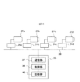
図3は図1に示す表示装置の第1の実施形態の全体概略構成を示す図であって、7は駆動回路、8は記憶部であり、図1に対応する部分には同一符号を付けている。 FIG. 3 is a diagram showing an overall schematic configuration of the first embodiment of the display device shown in FIG. 1, wherein 7 is a drive circuit, 8 is a storage unit, and parts corresponding to those in FIG. ing.
同図において、記憶部8には、図2に示すコマ映像Ga〜Gpを表わす映像データが記憶されている。制御部6は、駆動回路7を制御することにより、回転機構部2を駆動して視野角制限フィルタ付きスクリーン3を回転させ、また、記憶部8から映像データを読み出して電子式プロジェクタ1に供給し、図2に示すような映像を投影させる。かかるコマ映像Ga〜Gpからなる投影映像としては、コンピュータグラフィックなどで任意に作成してもよいし、後述するように、CCDカメラで撮像して作成するようにしてもよい。また、CCDカメラで撮像して作成する場合には、この作成を遠隔地で行ない、作成された映像データを受信して記憶部8に記憶するようにしてもよい。
In the figure, the
以上の構成により、制御部6は記憶部8から映像データを読み出し、電子式プロジェクタ1に供給する。電子式プロジェクタ1は、受信した映像データにより、図2に示すような映像を出射する。出射されたこの映像は、ミラー4で反射された後、その各コマ映像Ga〜Gp毎に多角形ミラー5の異なるミラーで反射されて、視野角制限フィルタ付きスクリーン3に投影される。これにより、図4に示すように、視野角制限フィルタ付きスクリーン3の周囲からこの視野角制限フィルタ付きスクリーン3を見る方向をa〜pとすると、これらa〜p方向から夫々コマ映像Ga〜Gpが視野角制限フィルタ付きスクリーン3に投影される。この結果、図5に示すように、視野角制限フィルタ付きスクリーン3をその周囲から見る方向に応じて、この視野角制限フィルタ付きスクリーン3に異なるコマ映像Ga〜Gpが表示されることになる。図5において、コマ映像Ga〜Gpは夫々図4に示すa〜p方向から見た場合の視野角制限フィルタ付きスクリーン3に投影される映像であり、例えば、a方向から視野角制限フィルタ付きスクリーン3を見た場合、この視野角制限フィルタ付きスクリーン3の面がこのa方向に向いたとき、コマ映像Gaがこの視野角制限フィルタ付きスクリーン3に表示されて見ることができる。
With the above configuration, the
かかる構成によると、視野角制限フィルタ付きスクリーン3を一方向(例えば、図4でのa方向)から見続けると、視野角制限フィルタ付きスクリーン3の面がこのa方向を向いたとき、コマ映像Gaがこの視野角制限フィルタ付きスクリーン3に投影された表示されることになり、このために、a方向からはこのコマ映像を見ることができる。即ち、このコマ映像Gaが表示されるのは、視野角制限フィルタ付きスクリーン3が1回転する毎に1回表示されるものである。そこで、立体映像の1側面であるこのコマ映像Gaがちらつかず、連続した映像として見えるようにするためには、コマ映像Gaを見始めてから眼の残像によって視覚に残っている状態にあるときに、視野角制限フィルタ付きスクリーン3が1回転して次のコマ映像の表示を行なうように、視野角制限フィルタ付きスクリーン3の回転速度が設定されなければならない。このようにして、この視野角制限フィルタ付きスクリーン3の最低の回転速度が決まることになる。
According to this configuration, when the
図6(a)は図1における視野角制限フィルタ付きスクリーン3の一具体例の一部を示す断面図、同図(b)はその斜視図であって、9aはスクリーン板状部材、9bは視野角制限フィルタ、10はフィンである。
6A is a sectional view showing a part of one specific example of the
同図(a),(b)において、視野角制限フィルタ付きスクリーン3は、スクリーン板状部材9aの両面に、複数の遮光性のフィン10からなる視野角制限フィルタ9bが設けられている。これらフィン10は、例えば、厚さが100〜200μm程度であって、視野角制限フィルタ付きスクリーン3での画素の寸法程度、例えば、0.5〜2mm程度のピッチで設けられており、図2に示す映像が投写されたとき、いずれの方向からこの視野角制限フィルタ付きスクリーン3を見ても、多角形ミラー5の隣りのミラーで投影されるコマ映像(隣りのコマ映像)が遮光されて、その方向毎に該当するミラーで投影されたコマ映像だけが見えるようにするものである。
In FIGS. 2A and 2B, the
視野角制限フィルタ9bは、フィン10により、視野角を制限して隣りのコマ映像が見えないようにするものであるが、視野制限角度(可視範囲)に応じて、フィン10の高さが設定される。ここで、視野制限角度は、±360゜/(一周のコマ映像数×4)程度が与えられる。例えば、投写映像のコマ映像数が、図2に示すように、16コマである場合には、視野制限角度(可視範囲)は±5.6゜(=±360゜/(16×4))程度であり、このためのフィン10の高さは5〜20mm程度である。また、10コマの場合には、視野制限角度は±9.0゜(=±360゜/(10×4))程度であり、このためのフィン10の高さは3.2〜13mmで程度ある。
The viewing
あるいはまた、視野制限角度が±5.6゜(16コマの場合)程度の場合、3〜20程度の厚さの、また、視野制限角度が±9.0゜(10コマの場合)程度の場合、1.9〜13mm程度の厚さの夫々透明フィルムまたは透明基板(図示せず)の中に、フィン10と同じ作用をする50〜200μm程度の厚さの遮光仕切り(図示せず)を0.3〜2mm程度のピッチで挿入した構成とすることもできる。また、これ以外にも、視野角制限方向に集光させるシリンドリカルレンズを配置した構成としてもよい。
Alternatively, when the viewing angle is about ± 5.6 ° (for 16 frames), the thickness is about 3 to 20, and the viewing angle is about ± 9.0 ° (for 10 frames). In this case, a light shielding partition (not shown) having a thickness of about 50 to 200 μm that performs the same function as the
図1における視野角制限フィルタ付きスクリーン3の他の具体例としては、特開平11ー258697号公報に記載されるような指向性反射スクリーン材を用いるようにしてもよい。図7はかかる指向性反射スクリーン材を用いた視野角制限フィルタ付きスクリーン3を示す断面図であって、11は指向性反射材スクリーン、12は視野角制限フィルタである。また、図8は図7における指向性反射材スクリーン11の構成を示す斜視図であって、11aはコーナミラーシート、11bはレンチキュラーシートである。
As another specific example of the
図7において、この具体例は、指向性反射材スクリーン11に視野角制限フィルタ12が設けられた構成をなしている。指向性反射材スクリーン11は、図8に示すように、コーナーミラーシート11aとレンチキュラーシート11bとで構成されており、入射した光に対して水平方向には再帰性反射、垂直方向には、拡散反射をする特性を持っていて、入射角が±45゜以内で入射した光を入射してきた方向へ反射する。即ち、この指向性反射材スクリーン11がこれを見ている人に正対した状態から左右±45゜の範囲内で回転する間、この人は同じ映像を見ることができる。従って、かかる指向性反射材スクリーン11を用いた視野角制限フィルタ付きスクリーン3は、図6に示す構成の視野角制限フィルタ付きスクリーン3に比べて、所定の方向に反射可能な入力角の範囲が広いため、反射光量が多く、その結果、図6に示す構成の視野角制限フィルタ付きスクリーン3を用いた場合に比べて、明るい映像が得られることになる。
In FIG. 7, this specific example has a configuration in which a viewing
しかし、指向性反射材スクリーン11だけを用いたのでは、光の入射する角度によっては、入射してきた方向とは異なる方向に反射してしまう場合もあり、その結果、見る方向によっては、複数の方向からのコマ映像が重なり合って見えてしまうこともある。そこで、このような他の方向からの反射光を防ぎ、見る人が方向に応じたコマ映像だけを見ることができるようにするために、図7に示すように、視野角制限フィルタ12も設けているものである。この視野角制限フィルタ12は、図6に示す視野角制限フィルタ9bと同様、細かいピッチでフィンを配列した構造をなすものである。指向性反射材スクリーン11の表面に、例えば、その法線に対して±約24度の視野角制限(可視範囲)を有する視野角制限フィルタ(視野角制限光学系)12を貼り付けることにより、近隣からのコマ映像の反射光が遮光されてa〜p方向(図4)からは、図9に示すように、正しい方向からのコマ映像のみが表示されてこれのみを見ることができるようになる。その結果、視野角制限フィルタ付きスクリーン3の周囲を巡って見る方向をa,b,c,……,pと変えていくと、その見る方向毎にその見る方向に応じた物体のコマ映像Ga〜Gp(図5)のみを見ることが可能となり、複数人が任意の方向から同時に映像を楽しめるという効果が得られる。また、指向性反射材スクリーン11を2枚背中合わせに接着し、夫々の指向性反射材スクリーン11の表面に視野角制限フィルタ12を貼り合わせることにより、両面タイプの視野角制限フィルタ付きスクリーン3を作ることができる。両面タイプの視野角制限フィルタ付きスクリーン3を用いる場合、片面タイプの視野角制限フィルタ付きスクリーン3と違って、スクリーンが1回転する間に2回ある方向の鏡から投影された映像を見ることになり、より明るい映像を見ることができる。
However, when only the
図10は図1に示す表示装置の第1の実施形態の変形例であって、図1に対応する部分には同一符号を付けて重複する説明を省略する。 FIG. 10 is a modification of the first embodiment of the display device shown in FIG. 1, and portions corresponding to those in FIG.
同図において、この変形例では、電子式プロジェクタ1が天井に固定され、その垂直方向下方に回転機構部2や視野角制限フィルタ付きスクリーン3が設置されており、電子式プロジェクタ1から出射されたコマ映像は円錐面状の多角形ミラー5で反射されて、図4に示すa〜p方向から回転する視野角制限フィルタ付きスクリーン3に投影される。これにより、この視野角制限フィルタ付きスクリーン3では、その向き(即ち、見る方向)に応じて、図5に示すようなコマ映像Ga〜Gpが表示される。
In this figure, in this modification, an
以上のように、この第1の実施形態では、複数人が任意の方向から同時に立体映像を楽しむことができ、多角形ミラー5の各ミラーの調整も必要ないし、かかるミラーの位置や向きなどに微妙な狂いによる誤差も軽減できる。しかも、多角形ミラー5を視野角制限フィルタ付きスクリーン3に近づけて配置できるため、装置全体を小型化できるし、視野角制限フィルタ付きスクリーン3の近くで立体映像を見ることができる。
As described above, in the first embodiment, a plurality of people can enjoy a stereoscopic image from any direction at the same time, it is not necessary to adjust each mirror of the
また、電子式プロジェクタ1からは図2に示すような全てのコマ映像を含む投影映像を常時出射することができるため、コマ映像毎の出射タイミングを考慮する必要はないし、この電子式プロジェクタ1から出射されたコマ映像は視野角制限フィルタ付きスクリーン3に投影され、この投影されたコマ映像を人が見るものであるから、鮮明な立体映像をどの方向,位置からも見ることができる。
Further, since the projection image including all the frame images as shown in FIG. 2 can be always emitted from the
なお、以上の説明では、電子式プロジェクタ1を視野角制限フィルタ付きスクリーン3の回転軸下方に設置して上向きに投影を行なうものとしたが、これらの上下位置の定義は、理解を容易にするために、回転軸や映像が形成される位置との関係で用いているものであり、例えば、表示装置の設置場所の床や天井との位置関係に限定されるものではなく、また、上下が逆でもよい。
In the above description, the
図11は図2に示す投影映像を作成する本発明による撮像装置の原理を示す図であって、13はCCDカメラ、14は多角形ミラー、15は物体(撮影対象)である。 FIG. 11 is a diagram showing the principle of the imaging apparatus according to the present invention that creates the projection image shown in FIG. 2, wherein 13 is a CCD camera, 14 is a polygon mirror, and 15 is an object (photographing target).
同図において、多角形ミラー14は、図1に示す多角形ミラー5と同様、円錐面上に配列された複数のミラーからなり、この円錐面の中心軸(図示せず)を中心として撮影対象となる物体15が配置される。また、この円錐面の中心軸に沿う上方に、下向きにして、CCDカメラ13が設けられている。このCCDカメラ13の撮像視野内に多角形ミラー14全体が含まれる。多角形ミラー14の各ミラーは図4でのa〜p方向に対応するものであり、多角形ミラー14の各ミラーで反射された物体15の映像は夫々、コマ映像として、CCDカメラ13により撮像される。これにより、例えば、図2に示すような映像が得られる。なお、CCDカメラ13によって撮像される映像は、静止画でも、また、動画でもよい。
In the same figure, a
図12は図11に示す原理を用いた本発明による撮影装置の第1の実施形態を示す構成図であって、16はミラーであり、図11に対応する部分には同一符号を付けている。 FIG. 12 is a block diagram showing the first embodiment of the photographing apparatus according to the present invention using the principle shown in FIG. 11, wherein 16 is a mirror, and parts corresponding to those in FIG. .
同図において、ここでは、撮影対象15を人物とするものであり、この人物15の全身の映像を得るものである。ミラー16は、CCDカメラ13よりも上方の天井の裏面に取り付けられており、また、CCDカメラ13はこのミラー16側を向いている。多角形ミラー14の各ミラーは、図11での多角形ミラー5の各ミラーと同様、円錐面に配置されている。
In this figure, here, the photographing
人物15のa〜p方向(図4)から見た映像は夫々、多角形ミラー14対応するミラーで反射され、さらに、天井のミラー16で反射されてCCDカメラ13で撮像される。これにより、図2に示すような映像が得られる。この場合、多角形ミラー14でミラー16の方向に光が反射されるものであれば、撮像対象に制限がなく、また、複数の撮像対象が含まれてもよい。
Images of the
図13は本発明による表示装置の第2の実施形態を示す構成図であって、17は図11に示す原理に基づく投影映像の撮影装置、18は通信路であり、図3及び図11に対応する部分には同一符号を付けて重複する説明を省略する。 FIG. 13 is a block diagram showing a second embodiment of the display device according to the present invention, in which 17 is a projection image photographing device based on the principle shown in FIG. 11, 18 is a communication channel, and FIGS. Corresponding portions are denoted by the same reference numerals and redundant description is omitted.
同図において、この第2の実施形態では、表示装置が通信路18を介して撮像装置17と接続されている。撮像装置17では、CCDカメラ13で、図11で説明したようにして、投影映像が得られると、この投影映像を処理してNTSC/PALなどの映像信号を生成し、これを表示装置に通信路18を介して送信する。表示装置では、この映像信号を受信すると、もとの撮像映像に変換し、電子式プロジェクタ1に供給する。これにより、先の第1の実施形態と同様に、視野角制限フィルタ付きスクリーン3にその回転に応じた物体15のコマ映像が表示され、しかも、投影映像の作成とともに、リアルタイムで立体映像の表示が可能となる。
In the figure, in the second embodiment, the display device is connected to the
ここで、通信路18としては、有線であっても、無線であってもよい。また、撮像装置17は、取得した投影映像をネットワークを介して遠隔地の表示装置に送信するようにするようにしてもよく、この場合には、MPEGなどのデジタル映像フォーマットのデータとして送ってもよい。これにより、遠隔地で、この表示装置により、物体15の立体映像を見ることができる。
Here, the
さらに、図11に示す撮影装置の原理を利用すれば、撮影対象に応じた大きさの撮影システムを作ることも可能である。即ち、被写体(撮像対象)の大きさに合わせて円錐面状の多角形ミラーの各ミラーの大きさと、これらミラーを配置する円の大きさを設定することで、撮像対象に応じた撮影装置を作ることができる。また、CCDカメラの設置位置も、その撮影視野内に円錐面状の内面多角形ミラー全体が納まり、多角形ミラーの全ミラーからのコマ映像を撮影できるように、高さが調整される。 Furthermore, if the principle of the photographing apparatus shown in FIG. 11 is used, a photographing system having a size corresponding to the subject to be photographed can be made. In other words, by setting the size of each mirror of the conical polygon mirror and the size of the circle in which these mirrors are arranged in accordance with the size of the subject (imaging target), an imaging device corresponding to the imaging target can be obtained. Can be made. The height of the CCD camera is also adjusted so that the entire conical inner polygonal mirror can be accommodated in the field of view of the CCD camera, and frame images can be taken from all the mirrors of the polygonal mirror.
図14は本発明による表示装置の第3の実施形態を示す外観斜視図であって、19はセンサであり、図1に対応する部分には同一符号を付けて重複する説明を省略する。 FIG. 14 is an external perspective view showing a third embodiment of a display device according to the present invention. 19 is a sensor, and the same reference numerals are given to portions corresponding to those in FIG.
この第3の実施形態は、インタラクションを可能としたものであって、図14に示すように、表示装置の周囲の複数箇所にセンサ19を設けたり、図示しないが、床面にマットスイッチを敷くなどの方法を用いることにより、人が近づいてきたことを検知することができるようにしている。また、見る人の方向a〜p(図4)を検知する手段としては、赤外線や近接センサ,マイクなどを検知したい方向の数だけ(例えば、a〜p方向の16個)使用すればよい。このとき、隣り合うセンサから得られる信号の変化から、見る人の凡その動きなどを検知することができる。
This third embodiment enables interaction, and as shown in FIG. 14,
いま、図示するように、センサ19が設けられているとすると、センサ19で得られた信号は制御部6で処理される。制御部6は、見る人の動きに応じた映像を電子式プロジェクタ1に送信する。例えば、センサ19の信号の変化から人が近づいてきた方向を検知し、視野角制限フィルタ付きスクリーン3に投影されているキャラクタをこの近づいて来た人と正対するように、この視野角制限フィルタ付きスクリーン3を回転させるなどのインタラクションが可能である。このとき、キャラクタが回転させるようにする映像の作成方法は、制御部6に図5に示すコマ映像Ga〜Gpを記憶しておき、例えば、図2に示すような映像を電子式プロジェクタ1で投影する際に、コマ映像Ga〜Gpを周方向に1コマ、または数コマずつずらした映像を投影することにより、キャラクタが回転しているような動きを作ることができる。コマ映像のいずれが正面にあるかなどを示す方向の情報を予め記憶しておき、人が居ると検知された方向に正面映像が形成されるように制御してもよい。
As shown in the figure, if a
また、隣り合うセンサ19の信号変化から、例えば、人の手が動いた向きや移動に合わせてキャラクタの向きを返るといったインタラクションの可能である。さらに、複数のセンサ19を取り付けることで、複数の人の接近や動作を検出して、これに対応して映像を作ることもできる。
Further, it is possible to perform an interaction such as returning the direction of the character in accordance with the direction in which the human hand moves or the movement from the signal change of the
図15は本発明による表示装置の第4の実施形態を示す外観斜視図であって、3aは視野角制限フィルタ付きスクリーンであり、図1に対応する部分には同一符号を付けている。
FIG. 15 is an external perspective view showing a fourth embodiment of a display device according to the present invention.
同図において、この第4の実施形態は、半円筒状をなすものであって、図15に示すように、多角形ミラー5が半円錐面状に配列された複数のミラーから構成されている。視野角制限フィルタ付きスクリーン3aは、回転機構部(回転駆動源)2により、連続的またはステップ的に回転駆動される。ミラー4は天井の裏面に貼り付けられている。これら多角形ミラー5とミラー4とで投影光学系が形成される。電子式プロジェクタ1は、例えば、図16に示すように、半円状にコマ映像Gb〜Giが配列された投影映像を出射する。制御部6はかかる投影映像を記憶しており、電子式プロジェクタ1に供給する。
In the same figure, this 4th Embodiment makes a semi-cylindrical shape, As shown in FIG. 15, it is comprised from the some mirror by which the
図17は図15に示す第4の実施形態の縦断面図である。 FIG. 17 is a longitudinal sectional view of the fourth embodiment shown in FIG.
同図において、電子式プロジェクタ1は、制御部6から供給される図16で示すような投影映像を出射する。この映像は天井裏のミラー4で反射され、さらに、この映像の各コマ映像Gb〜Giが多角形ミラー5の夫々のミラーで反射されて視野角制限フィルタ付きスクリーン3aに投影される。
In the figure, the
電子式プロジェクタ1から出射される投影映像は、図16に示すように、リング領域に物体を周囲から見たときの分割されたコマ映像Gb〜Gi(図5と同様)を円周方向、半円状に並べた映像である。かかる映像の作成方法としては、コンピュータグラフィックなどで任意に作成してもよいし、図11で説明した方法により、CCDカメラの撮影によって作成するようにしてもよい。
As shown in FIG. 16, the projected image emitted from the
この表示装置の第4の実施形態では、以上の構成により、制御部6が、例えば、図16に示す映像データを読み出して電子式プロジェクタ1に供給する。電子式プロジェクタ1は、供給された映像データの投影映像を出射する。出射された投影映像のリング領域の分割された各コマ映像Gb〜Giの光は、天井裏面のミラー4で反射した後、さらに、半円錐面状に配列された多角形ミラー5の各ミラー面で反射され、例えば、図4に示すb〜i方向からコマ映像Gb〜Giが視野角制限フィルタ付きスクリーン3aに投影される。視野角制限フィルタ付きスクリーン3aは、後ろ側から投影された映像を透過する性質を持つスクリーンであるが、見る方向によって異なる映像が見れるように水平方向には視野角を制限し、さらに、垂直方向には、広い視野角範囲を持つスクリーンであることが望ましい。そこで、背面投射型ディスプレイで使用されるような半透過拡散スクリーンなどを利用する。
In the fourth embodiment of the display device, the
視野角制限フィルタ付きスクリーン3aの実現方法の1つとして、フレネルレンズを用いる方法が考えられる。
As one method for realizing the
図18はフレネルレンズ20の特性を示す図である。
FIG. 18 is a diagram illustrating the characteristics of the
同図において、フレネルレンズ20は、レンズ曲面が連続ではなく、階段状にしたリンズである。このフレネルレンズ20を用いると、光が入射した方向の延長線上へ透過し、ある位置で集光するため、見る人は、半円錐面状に配置された多角形ミラー5の各ミラーとかかるフレネルレンズ20を用いたスクリーン(フレネルレンズスクリーン)1aとを結ぶ一直線上のある位置から、ちょうどそのミラーに映った映像を見ることができる。即ち、フレネルレンズ20を用いることで、第1の実施形態で説明した再帰性反射と同様に、見る方向に応じた映像を見ることができるという効果が得られる。
In the same figure, the
また、フレネルレンズスクリーン3aの角度が、見る人に正対している角度から一定範囲内(視野角の範囲内)にある間は、このスクリーン3aに投影された映像を見ることができる。
Further, while the angle of the
図19はフレネルレンズの2種類のタイプを示すものであり、図19(a)に示すフレネルレンズ20aは同心円状に曲面状のカットが施されたものであって、最も一般的なものである。このフレネルレンズ20aは、水平方向にも、垂直方向にも集光するため、図15,図17における視野角制限フィルタ付きスクリーン3aに用いると、多角形ミラー5の各ミラーで反射されたコマ映像を水平方向,垂直方向ともにフレネルレンズが持つ視野角の範囲からしか、見ることができない。
FIG. 19 shows two types of Fresnel lenses, and the
そこで、図19(b)に示す水平方向にだけ階段状のカットが施されたフレネルレンズ20bを視野角制限フィルタ付きスクリーン3aに用いると、水平方向にだけ集光するため、視野角制限フィルタ付きスクリーン3aの材料して適当である。
Therefore, when the
また、垂直方向の集光を抑え、映像をより広範囲に見えるようにするためには、垂直方向に拡散反射するように加工すればよい。図20はその一具体例を示すものであって、フレネルレンズに垂直方向の拡散反射の作用を持たせたものでる。これは、図8に示すレンチキュラーシート11bと同様のレンチキュラーシート21をフレネルレンズ20のレンズ面に貼り合わせたものであり、垂直方向の拡散反射を実現したものである。これにより、視野角制限フィルタ付きスクリーン3aの全面が、垂直方向に、より均一な明るさに見えるようになり、見易くなる。
Further, in order to suppress the light collection in the vertical direction and to make the image appear in a wider range, it may be processed so as to be diffusely reflected in the vertical direction. FIG. 20 shows a specific example thereof, in which a Fresnel lens is given a function of diffuse reflection in the vertical direction. In this example, a
図21はフレネルレンズを用いた場合の図15における視野角制限フィルタ付きスクリーン3aを示す(上から見た)構成図であって、前出図面に対応する部分には同一符号を付けている。
FIG. 21 is a configuration diagram (viewed from above) of the
同図において、フレネルレンズ20に図20に示す拡散反射のためのレンチキュラーシート21を貼り合わせる。さらに、視野角を制限するために、図6に示した視野角制限フィルタ9bと同様に、フィンを取り付けて視野角制限フィルタ22を形成し、目的の視野角を制限するか、または、PCや携帯電話の液晶画面でも使用されているような視野角制限フィルタを用いる。
In the figure, a
以上説明した第4の実施形態では、第1の実施形態とは異なり、視野角制限フィルタ付きスクリーン3aの背面から投影した映像を見ることになるので、視野角制限フィルタのフィンのエッジに直接光が当たることがなくなり、ちらつきも少なくなる。これにより、コントラストがはっきりとした映像を見ることができる。また、この第4の実施形態では、全周を巡ることができない代わりに、多角形ミラー5が設置されていない方向から近づいてみることができる。そのため、全周タイプの表示装置に比べて、視野角制限フィルタ付きスクリーン3aに近づくことができる。さらに、第1の実施形態のような円筒状の表示装置では、視野角制限フィルタ付きスクリーン3やこれに表示される映像を大きくするためには、装置全体を大きくする必要があり、見る人とこのスクリーン3との距離も開いてしまうという問題もある。しかし、この第4の実施形態では、装置自体を大きくしても、スクリーン3aと見る人との間の距離に影響は及ばない。
In the fourth embodiment described above, unlike the first embodiment, an image projected from the back surface of the
また、表示装置の第1の実施形態では、図2に示すようなリング状にコマ映像Ga〜Gp(16コマの場合)が配置された投影映像を電子式プロジェクタ1から投射するものであった。しかし、この第4の実施形態では、図16に示すような半円状にコマ映像Gb〜Gi(8コマの場合)が配置された投影映像を電子式プロジェクタ1が投射する。電子式プロジェクタ1から投射される投影映像の解像度が同じとした場合、必要なコマ映像が表示装置の第4の実施形態の方が、第1の実施形態の場合の半分となる。このため、この第4の実施形態での電子式プロジェクタ1が投射される各コマ映像の解像度は、この第1の実施形態での電子式プロジェクタ1から投射されるコマ映像の解像度の4倍となり、投影されたコマ映像の表現力が向上する。
Further, in the first embodiment of the display device, the projection image in which the frame images Ga to Gp (in the case of 16 frames) are arranged in a ring shape as shown in FIG. 2 is projected from the
なお、以上の表示装置の第4の実施形態では、多角形ミラーを半円状のものとしたが、ミラーが配列されている円筒を半分以上、半分以下とすることも可能であり、この場合には、映像を観賞可能な角度方向は、円筒内にミラーが配置された角度方向の範囲によって決まる。また、光の透過性を持ち、かつ反射を抑えることができる視野角制限フィルタ付きスクリーンを用いて、表示装置の第1の実施形態のように、全周囲の円筒状の表示装置とすることも可能である。 In the fourth embodiment of the display device described above, the polygonal mirror is a semicircular shape, but the cylinder in which the mirror is arranged may be half or more and half or less. In this case, The angle direction in which the image can be viewed is determined by the range of the angle direction in which the mirror is arranged in the cylinder. In addition, a screen with a viewing angle limiting filter that can transmit light and suppress reflection can be used to form a cylindrical display device around the entire periphery as in the first embodiment of the display device. Is possible.
図22は本発明による表示装置の第5の実施形態を示す要部構成図であって、1a〜1dは電子式プロジェクタ、25a〜25dは投射光学系、26a〜26dは投影領域であり、前出図面に対応する部分には同一符号を付けている。 FIG. 22 is a main part configuration diagram showing a display device according to a fifth embodiment of the present invention, wherein 1a to 1d are electronic projectors, 25a to 25d are projection optical systems, and 26a to 26d are projection areas. Portions corresponding to the outgoing drawings are given the same reference numerals.
同図において、この第5の実施形態は、電子式プロジェクタを複数用いるものであり、ここでは、4個の電子式プロジェクタ1a〜1dが用いられているものとする。これら電子式プロジェクタ1a〜1dは多角形ミラー(ミラー群)5の上方に配置されており、しかも、これら電子式プロジェクタ1a〜1dの投射光学系25a〜25dの中心が視野角制限フィルタ付きスクリーン3の回転軸23の延長軸24を中心とする同一半径の円周上にあって、かつ等間隔(延長軸24からみて90度の間隔)となるように、これら電子式プロジェクタ1a〜1dが配置されている。
In the figure, the fifth embodiment uses a plurality of electronic projectors, and here, it is assumed that four
このように配置された電子式プロジェクタ1a〜1dは夫々、多角形ミラー5をその一部ずつ投影する。投影領域26aは電子式プロジェクタ1aから出射される映像が投影される領域であり、この投影領域26aでは、多角形ミラー5のうちの少なくとも、
(多角形ミラー5を構成するミラーの個数)÷(電子式プロジェクタの個数)
のミラーが完全に、かつこの投影領域26a一杯に含まれる。ここで、多角形ミラー5を構成するミラー数を24個とすると、電子式プロジェクタの個数は4個であるから、投影領域26aに完全に含まれるミラーの個数は少なくとも6個である。
Each of the
(Number of mirrors constituting the polygon mirror 5) ÷ (Number of electronic projectors)
Are completely included in the
投影領域26bは電子式プロジェクタ1bから出射される映像が投影される領域であり、この投影領域26bには、投影領域26aに完全に含まれる6個のミラーに続く6個のミラーが完全に、かつこの投影領域26b一杯に含まれる。同様にして、投影領域26cは電子式プロジェクタ1cから出射される映像が投影される領域であり、この投影領域26cには、投影領域26bに完全に含まれる6個のミラーに続く6個のミラーが完全に、かつこの投影領域26c一杯に含まれる。投影領域26dは電子式プロジェクタ1dから出射される映像が投影される領域であり、この投影領域26dには、投影領域26c,26aに完全に含まれる6個ずつのミラー間の6個のミラーが完全に、かつこの投影領域26d一杯に含まれる。なお、このことは、後述する具体例についても同様である。
The
これを図23で説明する。いま、多角形ミラー5がミラー5(1)からミラー5(24)までの24個のミラーからなるものとすると、投影領域26aには、ミラー5(1)からミラー5(6)までが完全に含まれ、投影領域26bには、ミラー5(7)からミラー5(12)までが完全に含まれ、投影領域26cには、ミラー5(13)からミラー5(18)までが完全に含まれ、投影領域26dには、ミラー5(19)からミラー5(24)までが完全に含まれる。
This will be described with reference to FIG. Assuming that the
この表示装置の第5の実施形態では、多角形ミラー5が24個のミラー5(1)〜(24)から構成されるものであるから、図2に示すように、リング状に配列された24個のコマ映像を含む投射映像が用いられるものであるが、夫々の電子式プロジェクタ1a〜1dが6個ずつのコマ映像を分担して該当する投射領域に完全に含まれるミラーに投射する。図24は、例えば、電子式プロジェクタ1dから出射される投影映像を示すものであり、この投影映像には、6個のコマ映像が投影領域26dでのミラー5(19)〜5(24)の配列に対応した配列で含まれている。そして、これら6個のコマ映像がこれらミラー5(19)〜5(24)に投射されるのであるが、これらのコマ映像の中心が該当するミラーの面の中心と一致して投射されるように、電子式プロジェクタ1dの開口25d(図22)の位置や向きが設定される。このことは、他の電子式プロジェクタ1a〜1cについても同様である。
In the fifth embodiment of the display device, the
各電子式プロジェクタ1a〜1dから出射された投影映像でのコマ映像は夫々、多角形ミラー5の該当するミラーで反射され、回転する視野角制限フィルタ付きスクリーン3に投影される。ここで、先の表示装置の第1〜第4の実施形態のように、電子式プロジェクタ1の投射口が視野角制限フィルタ付きスクリーン3の回転軸23の延長軸24上にある場合には、多角形ミラー5の各ミラーの面を同じ円錐面上に配置することにより、視野角制限フィルタ付きスクリーン3上に良好にコマ映像が投影されるが、この第5の実施形態のように、電子式プロジェクタ1a〜1dの投射口25a〜25dがこの延長軸24からずれている場合には、多角形ミラー5の各ミラーの面を同じ円錐面上に配置したのでは、多角形ミラー5の各ミラーで反射されたコマ映像は、視野角制限フィルタ付きスクリーン3上でずれた位置に投影されることなる。そして、このように投影位置にずれが生ずると、見る人が視野角制限フィルタ付きスクリーン3の周りを移動しながらこの視野角制限フィルタ付きスクリーン3の投影映像を見ていくと、その投影映像が見る位置に応じて位置が変動し、不自然な表示となる。例えば、この表示される投影映像が静止した物体の映像とすると、視野角制限フィルタ付きスクリーン3の周りを移動しながらこの投影映像を見た場合、この投影映像が上下・左右に動いて見えることになる。
The frame images of the projected images emitted from the
視野角制限フィルタ付きスクリーン3に表示された投影映像のこのような不自然な動きをなくすために、この第5の実施形態では、電子式プロジェクタ1a〜1dがコマ映像を投射する多角形ミラー5での6個のミラーを組として、各組毎に夫々のミラーの向きを調整する。
In order to eliminate such unnatural movement of the projected image displayed on the
即ち、夫々のミラーは、対応する電子プロジェクタから投射されるコマ映像をミラー面で反射して視野角制限フィルタ付きスクリーン3に投影する際に、電子式プロジェクタ−ミラー−スクリーン間に形成される光学系の光路上の適切な位置・角度となるように、調整する。
That is, each mirror reflects an optical image formed between the electronic projector, the mirror, and the screen when the frame image projected from the corresponding electronic projector is reflected on the mirror surface and projected onto the
即ち、いま、図25により、電子式プロジェクタ1aに関して説明すると、電子式プロジェクタ1aから出射される投影映像での各コマ映像の中心の光線が、多角形ミラー5での夫々に該当するミラー5(1),5(2),5(3),5(4),5(5),5(6)の中心で反射された後、視野角制限フィルタ付きスクリーン3の回転軸23に集まるように、さらに具体的には、この視野角制限フィルタ付きスクリーン3の中心位置に集まるように、これらミラー5(1),5(2),5(3),5(4),5(5),5(6)の傾きを設定する。
That is, now, the
そこで、いま、これらミラー5(1)〜5(6)の中心位置、即ち、ミラー5(3)とミラー5(4)との境界の傾きを持つ円錐面を想定し、この円錐面のこの境界位置にミラーを配置したとき、電子式プロジェクタ1aからの出射光の中心の光がこのミラーの中心で反射されて視野角制限フィルタ付きスクリーン3の中心に照射されるように、この円錐面が傾斜を持つものとすると、これらミラー5(1)〜5(6)をこの想定される円錐面に対して傾かせる。具体的な数値については、計算によって求めることができるので、省略するが、ミラー5(3)とミラー5(4)との境界を中心として、ミラー5(3)とミラー5(4)とを互い向き合う方向に等角度想定される円錐面から傾かせ、ミラー5(2)とミラー5(5)とを互い向き合う方向に等角度想定される円錐面から傾かせ、ミラー5(1)とミラー5(6)とを互い向き合う方向に等角度想定される円錐面から傾かせる。この場合、ミラー5(3),5(4)の傾き角よりもミラー5(2),5(5)の傾き角を大きくし、さらに、ミラー5(2),5(5)の傾き角よりもミラー5(1),5(6)の傾き角を大きくする。
Therefore, a conical surface having an inclination of the center position of these mirrors 5 (1) to 5 (6), that is, the boundary between the mirror 5 (3) and the mirror 5 (4) is assumed. When the mirror is arranged at the boundary position, this conical surface is so reflected that the light at the center of the emitted light from the
このように、ミラー5(1)〜5(6)を想定される円錐面に対して傾いた状態に設定することにより、電子式プロジェクタ1aから出射された各コマ映像の中心光は夫々、ミラー5(1)〜5(6)の中心位置で反射された後、視野角制限フィルタ付きスクリーン3の中心位置に集まることになる。そして、その結果、回転する視野角制限フィルタ付きスクリーン3では、多角形ミラー5の各ミラーで反射されて投影されるコマ映像が正しい位置に表示され、図26に示すように、装置の周りを周りながら視野角制限フィルタ付きスクリーン3に表示される立体映像を見ても、この立体映像の不自然な動きや揺れが現われず、良好な立体映像を見ることができる。
In this way, by setting the mirrors 5 (1) to 5 (6) to be inclined with respect to the assumed conical surface, the center light of each frame image emitted from the
そして、この表示装置の第5の実施形態では、立体映像を表わす複数のコマ映像を複数(この場合、4個)の電子式プロジェクタ1a〜1dで分担して表示するものであるから、電子式プロジェクタ1a〜1d夫々についてみると、表示するコマ映像の個数が先の第1〜第4の実施形態に比べて少なく、その分電子式プロジェクタ1a〜1dから出射するときの夫々のコマ映像を大きくすることができるから、夫々のコマ映像を解像度の高い映像として投影することができる。そして、その結果、視野角制限フィルタ付きスクリーン3に投影される立体映像は解像度の高い高精細の画像となる。
In the fifth embodiment of the display device, a plurality of (4 in this case)
図27は図22における各電子式プロジェクタ1a〜1d毎の投影映像を作成するための本発明による撮影装置の他の実施形態を示す構成図であって、27a〜27dはCCDカメラなどの撮像デバイス、28a〜28dは撮像デバイス27a〜27dの光学系、29a〜29dは撮像領域、30は撮像対象であり、図22に対応する部分には同一符号を付けている。
FIG. 27 is a block diagram showing another embodiment of the photographing apparatus according to the present invention for creating projected images for each of the
図22における電子式プロジェクタ1a〜1d毎の投影映像を作成する場合には、図22,図26に示す表示装置において、視野角制限フィルタ付きスクリーン3を回転軸23(図25)から取り外し、これに、図27に示すように、これら投影映像の対象物体となる撮像対象30を取り付ける。
When creating projection images for each of the
つまり、図22,図26において、視野角制限フィルタ付きスクリーン3が設置されていた位置が撮像対象の設置領域となる。
That is, in FIGS. 22 and 26, the position where the
また、これとともに、電子式プロジェクタ1a〜1b(図22)を取り外し、代わりに撮像デバイス27a〜27dを取り付ける。これら電子式プロジェクタ27a,27b,27c,27dは夫々、多角形ミラー5に対し、撮像領域29a,29b,29c,29dを撮像するが、ここで、撮像領域29aが図22,図23での電子式プロジェクタ1aの投影領域26aと一致するように(この場合、完全に一致する必要はないが、後述する解像度の点から、撮像領域29aでコマ映像として撮影するための複数のミラーが撮像領域29a一杯になるようにした方が好ましい。このことは、他の撮像領域29b〜29dについても、また、後述の表示装置の第6の実施形態の場合も同様である)、撮像デバイス27aの位置やその光学系28aの光軸の傾き(従って、撮像デバイス27aの向き)が設定され、同様に、撮像領域29bが図22,図23での電子式プロジェクタ1bの投影領域26bと一致するように、撮像デバイス27bの位置やその光学系28bの光軸の傾き(従って、撮像デバイス27bの向き)が設定され、撮像領域29cが図22,図23での電子式プロジェクタ1cの投影領域26cと一致するように、撮像デバイス27cの位置やその光学系28cの光軸の傾き(従って、撮像デバイス27cの向き)が設定され、撮像領域29dが図22,図23での電子式プロジェクタ1dの投影領域26dと一致するように、撮像デバイス27dの位置やその光学系28dの光軸の傾き(従って、撮像デバイス27dの向き)が設定される。
At the same time, the
これによると、図28に示すように、例えば、撮像デバイス27aは、その撮像領域29aでの多角形ミラー5の1つのミラー5(i)についてみると、このミラー5(i)に関して撮像対象30とは対称な位置にある仮想的な撮像対象30’を撮像することになる。撮像対象30についてのx(縦),y(横),z(高さ)の三次元座標系に対し、仮想的な撮像対象30’に対するu(縦),v(横),w(高さ)の三次元座標系は、ミラー5(i)の面のx,y,z座標系での傾きに応じて回転している。これにより、撮像デバイス27aは、ミラー5(i)を介して見る撮像対象30の側面と同じ仮想的な撮像対称30’の側面を同じ大きさで見ることができ、従って、ミラー5(i)を介して見ることができる撮像対象30の側面を撮像することができる。
According to this, as shown in FIG. 28, for example, when the
撮像領域29a内の多角形ミラー5の他のミラーについても同様であり、この撮像領域29aに含まれるミラー夫々から見た撮像対象30の側面が撮像デバイス27aによって同時に撮像される。このことは、他の撮像デバイス27b〜27dについても同様である。
The same applies to the other mirrors of the
このようにして、各撮像デバイス27a〜27dでは、撮像対象30の撮影が行なわれるが(この場合、これら撮像デバイス27a〜27dが同時に撮影してもよいし、別々のタイミングで撮影してもよい)、これにより、図29(a)に示されるような映像が得られる。即ち、撮像デバイス27aについてみると、この撮像デバイス27aの撮像領域29a(図27)に含まれる多角形ミラー5でのミラー全てで反射された撮像対象30の側面映像が含まれる撮影映像が得られることになる。
In this way, each of the
かかる撮影映像は処理されて、図29(b)に示すように、必要な側面映像のみがコマ映像として抽出された投影映像が作成される。この場合には、図23に示すように、投影領域26a(撮像領域29aに等しい)でのミラー5(1)〜5(6)からの側面映像が抽出され、コマ映像とする投影映像が作成される。他の撮像デバイス27b〜27dから得られる撮像映像についても同様であり、このようにして、図22での各電子式プロジェクタ1a〜1dから投射される投影映像が作成されることになる。
The captured video is processed to create a projected video in which only the necessary side video is extracted as a frame video, as shown in FIG. In this case, as shown in FIG. 23, side images from the mirrors 5 (1) to 5 (6) in the
なお、撮像デバイス27a〜27dの撮像映像から不要なミラーからの反射映像を取り除く方法としては、撮像デバイス27a〜27dの光学系28a〜28dにかかる不要なミラーからの映像光を遮光するマスクを設けるようにしてもよいし、あるいは撮像デバイス27a〜27dの出力映像信号にゲートをかけるなどして、かかる不要ミラーからの映像による信号成分を除去するようにしてもよい。
In addition, as a method of removing the reflected image from the unnecessary mirror from the captured images of the
図30はこの表示装置の第5の実施形態のための図27に示す撮像装置で投影映像を作成するときのシステム構成を示す図であって、31a〜31dはクライアント、32a〜32dは制御処理部、33a〜33dは記憶部、34a〜34dは通信部、35はサーバ、36は制御部、37は通信部、38は通信路であり、図27に対応する部分には同一符号を付けている。 FIG. 30 is a diagram showing a system configuration when a projected image is created by the imaging device shown in FIG. 27 for the fifth embodiment of the display device. 31a to 31d are clients, and 32a to 32d are control processes. , 33a to 33d are storage units, 34a to 34d are communication units, 35 is a server, 36 is a control unit, 37 is a communication unit, 38 is a communication path, and parts corresponding to FIG. Yes.
同図において、各クライアント31a〜31dは、その通信部34a〜34dにより、通信路38を介してサーバ35の通信部37と接続されている。また、各クライアント31a〜31dには、制御処理部32a〜32dと記憶部33a〜33dとが設けられている。また、サーバ35には、図示しない操作部の操作に応じて各種の指令信号を発生する制御部36が設けられている。ここでは、各電子式プロジェクタ1a〜1d(図22)の投影映像を作成するものであるから、クライアント31a〜31dの制御処理部32a〜32dに夫々、撮像デバイス27a〜27dが接続される。そして、これら撮像デバイス27a〜27dは夫々、図27で説明したように配置される。
In the figure, each of the
いま、サーバ35において、図示しない操作手段により、この表示装置の使用者が投影映像の作成のための指令操作をすると、制御部36が指令信号を生成し、通信部37から通信路38に送信する。この指令信号は通信路38によって伝送され、クライアント31a〜31dの通信部34aで受信される。クライアント31aでは、通信部34aで受信された指令信号により、制御処理部32aが撮像デバイス27aに撮像を開始させる。この撮像によって撮像デバイス27aから出力される映像信号は、制御処理部32aで処理された後、電子式プロジェクタ1a(図22)に用いる投影映像の映像信号として、記憶部33aに記憶される。この場合、制御処理部32aにおいて、多角形ミラー5(図27)の不要なミラーからの反射映像による信号成分を除去する処理を行なうようにしてもよい。これにより、記憶部33aには、電子式プロジェクタ1a(図22)に用いる投影映像が記憶されることになる。
Now, when the user of this display device performs a command operation for creating a projected image by operating means (not shown) in the
クライアント31b〜31dにおいても、同様であって、その記憶部33b,33c,33dに電子式プロジェクタ1b〜1d(図22)に用いる投影映像が記憶される。
The same applies to the
なお、静止画の立体映像を表示させる場合には、記憶部33a〜33dに記憶する投影映像のデータとしては、1フィールドもしくは1フレーム期間の映像データであればよいが、撮像対象30(図27)が動くものであって、かかる撮像対象30の立体映像を表示させる場合には、必要に応じた所定の期間の投射映像を記憶部33a〜33dに記憶させるようにする。以上のことから、この表示装置の使用者の操作によるサーバ35からの起動指令によって撮像デバイス27a〜27dを撮像開始させ、この使用者が静止画撮像の指令操作をすると、撮像デバイス27a〜27dの出力映像信号を1フィールドもしくは1フレーム期間抽出し、これを電子式プロジェクタ1a〜1dの投影映像のデータとして記憶部33a〜33dに記憶させるようにし、また、動画撮像の指令操作をすると(記憶部33a〜33d経の記録開始指令と記録終了指令とを出す)、この指令に応じた期間の撮像映像信号を投影映像のデータとして記憶部33a〜33dに記録するようにしてもよい。
Note that, when displaying a stereoscopic image of a still image, projection image data stored in the
このように、夫々のクライアント31a〜31dの記憶部33a〜33dに投影映像のデータを記録した後、これら投影映像を用いて立体映像の表示を行なう場合には、図31に示すように、クライアント31aでは、撮像デバイス27aを取り外して電子式プロジェクタ1aを取り付け、同様に、クライアント31b〜31dでは夫々、撮像デバイス27b〜27dを取り外して電子式プロジェクタ1b〜1dを取り付ける。このとき、これら電子式プロジェクタ1a〜1dは、図22で説明したように配置される。
As described above, when recording projection video data in the
このように構成された後、サーバ35の図示しない操作手段でこの表示装置の使用者が表示指令操作をすると、制御部36が表示指令信号を生成して通信部37から通信路38に送信する。各クライアント31a〜31dでは、この表示指令信号が通信部34a〜34dで受信され、制御処理部32a〜32dに供給される。これら制御処理部32a〜32dは、この表示指令信号を受けると、電子式プロジェクタ1a〜1dを起動させるとともに、記憶部33aから投影画像のデータを取り込み、電子式プロジェクタ1a〜1dに供給する。これにより、電子式プロジェクタ1a〜1dは夫々の投影映像を投射し、この結果、回転する視野角制限フィルタ付きスクリーン3(図22)によって立体映像が表示されることになる。
After the above configuration, when a user of the display device performs a display command operation using an operation unit (not shown) of the
なお、上記では、同一クライアント31a〜31dで撮像デバスス27a〜27dと電子式プロジェクタ1a〜1dとを取り替えて投影映像の作成とこの投影映像の投射とを行なうようにしたが、図22に示す電子式プロジェクタ1a〜1dの配置に対し、その配置関係を延長軸24の周りに所定角度回転した配置関係で、図27に示すように、撮像デバイス27a〜27dとを配置することにより、即ち、図22において、電子式プロジェクタ1a,1bの間に撮像デバイス27aを配置し、電子式プロジェクタ1b,1cの間に撮像デバイス27bを配置し、電子式プロジェクタ1c,1dの間に撮像デバイス27cを配置し、電子式プロジェクタ1d,1aの間に撮像デバイス27dを配置することにより、撮像デバスス27a〜27dと電子式プロジェクタ1a〜1dとの取替え作業を省くようにすることができる。この場合、図32に示すように、図22に示す電子式プロジェクタ1a〜1dの投影領域26a〜26d(実線で示す)を、回転軸23を中心に、多角形ミラー5のミラーの整数枚分回転させたものが、図27に示す撮像デバイス27a〜27dの撮像領域29a〜29dの位置(破線で示す)となるようにする。
In the above description, the
このような構成の場合、図33に示すように、同じクライアント31aに撮像デバイス27aとこれによって作成される投影映像を投射する電子式プロジェクタ1aとを接続することができ、同様にして、クライアント31bに撮像デバイス27bとこれによって作成される投影映像を投射する電子式プロジェクタ1bとを、クライアント31cに撮像デバイス27cとこれによって作成される投影映像を投射する電子式プロジェクタ1cとを、クライアント31dに撮像デバイス27dとこれによって作成される投影映像を投射する電子式プロジェクタ1dとを夫々接続することができる。そして、クライアント31a〜31dでは夫々、撮像デバイス27a〜27dの撮像によって得られて記憶部33a〜33dに記憶された投影映像のデータが、表示制御部39a〜39dの制御のもとに、読みだされて電子式プロジェクタ1a〜1dに供給され、夫々の投影映像が投射されることになる。
In the case of such a configuration, as shown in FIG. 33, an
この場合の回転する視野角制限フィルタ付きスクリーン3によって表示される立体映像は、撮像デバイス27a〜27dによって撮像されるもとの撮像対象の対し、上記の所定回転角度だけ回転軸23を中心に回転した映像となるが、見る人にとってはこのことは関係ない。なお、サーバ35は、撮像デバイス27a〜27dで撮像対象を撮像する指令と、電子式プロジェクタ1a〜1dで投影映像を投射させる指令を発することはいうまでもない。
In this case, the stereoscopic image displayed by the
また、以上のシステムでは、クライアント31a〜31d毎に記憶部33a〜33dを備えたものとしたが(図30,図31,図33)、図34に示すように、サーバ35に共通の記憶部40を設け、クライアント31a〜31dで生成された投影映像のデータをともにこの記憶部40で記憶するようにしてもよい。立体映像を表示する場合には、図示しない夫々の電子式プロジェクタにこの記憶部40から読み出した該当する投影映像のデータを供給するようにすればよい。なお、図34において、各クライアント31a〜31dで撮像デバイス27a〜27dと電子式プロジェクタとを交換するものとしているが、図33に示すように、撮像デバイスと電子式プロジェクタとを接続する構成としてもよい。
In the above system, the
さらに、以上の説明では、使用する電子式プロジェクタを4個としたが、これに限るものではなく、各電子式プロジェクタが等しい整数個ずつコマ映像を投射し、かつこれら電子式プロジェクタによって多角形ミラーを構成するミラーに過不足なくコマ映像を投射するものであるならば(即ち、多角形ミラーを構成するミラーの個数をm、使用する電子式プロジェクタの個数をnとしたとき、m÷nが整数となる電子式プロジェクタの個数m)、電子式プロジェクタの使用個数としては、4個に限るものではない。 Furthermore, in the above description, four electronic projectors are used. However, the present invention is not limited to this, and each electronic projector projects an equal integer number of frame images, and these electronic projectors provide polygon mirrors. If the number of mirrors constituting the polygonal mirror is m and the number of electronic projectors to be used is n, then m ÷ n is The number of electronic projectors m), which is an integer, and the number of electronic projectors used are not limited to four.
図35(a)は電子式プロジェクタを2個使用した場合を示すものであって、この場合には、夫々毎に投影領域26a,26bが設定され、多角形ミラー5を形成するミラーを半分ずつ(ここでは、多角形ミラー5が24個のミラーからなるものとしており、従って、12個ずつ)夫々の電子式プロジェクタがコマ映像の投射を受け持つことになる。また、図35(b)は電子式プロジェクタを6個使用した場合を示すものであって、この場合には、夫々毎に投影領域26a,26b,26c,26d,26e,26fが設定され、多角形ミラー5を形成するミラーを1/6の個数分ずつ(ここでは、多角形ミラー5が24個のミラーからなるものとしており、従って、4個ずつ)夫々の電子式プロジェクタがコマ映像の投射を受け持つことになる。
FIG. 35 (a) shows a case where two electronic projectors are used. In this case,
なお、以上の表示装置の第5の実施形態において、多角形ミラー5を撮像デバイス27a〜27dによる投影映像の作成のためと電子式プロジェクタ1a〜1dによる投射映像の投影のためとに用いたが、図13に示す表示装置の第2の実施形態のように、電子式プロジェクタ夫々に用いる投影映像を作成する撮像装置を別体に設け、作成された投影映像を夫々の電子式プロジェクタに送信するようにしてもよい。
In the fifth embodiment of the display device described above, the
次に、本発明による表示装置の第6の実施形態について説明する。
先に説明した表示装置の第5の実施形態では、投影映像を作成するための撮像デバイスと電子式プロジェクタとの使用個数を等しくしたものであるが、この表示装置の第6の実施形態では、この使用個数を異ならせたものである。即ち、この表示装置の第6の実施形態の電子プロジェクタを用いて立体映像を表示するための構成は基本的に図22に示す構成と同様であり、また、これら電子プロジェクタに用いる投影映像を作成するための撮像装置の構成も、基本的には、図27に示す構成と同様であるが、上記のように、撮像デバイスと電子式プロジェクタとの使用個数を異ならせるものである。
Next, a sixth embodiment of the display device according to the present invention will be described.
In the fifth embodiment of the display device described above, the number of imaging devices and electronic projectors used to create a projection image is equal, but in the sixth embodiment of this display device, The number used is different. That is, the configuration for displaying a stereoscopic image using the electronic projector of the sixth embodiment of the display device is basically the same as the configuration shown in FIG. 22, and the projection image used for these electronic projectors is created. The configuration of the imaging apparatus for this purpose is basically the same as that shown in FIG. 27, but the number of used imaging devices and electronic projectors is different as described above.
図36は撮像装置としては撮像デバイスを6個用い、表示装置としては電子式プロジェクタを4個用いた場合のこの表示装置の第6の実施形態でのこれら電子式プロジェクタに用いる投影映像の作成過程を示す図である。 FIG. 36 shows a process of creating a projection image used for these electronic projectors in the sixth embodiment of the display device when six image pickup devices are used as the image pickup device and four electronic projectors are used as the display device. FIG.
図36(a)は、撮像装置として構成される場合において、多角形ミラー5に対する各撮像デバイスの撮像領域を示すものであって、ここでは、多角形ミラー5を構成するミラーの個数を24個としている。ここで、多角形ミラーとしては、図22に示すように、立体映像を表示させるときに用いる多角形ミラー5であってもよいし(この場合には、撮像デバイスと電子式プロジェクタとは交換して使用されることになる)、また、投影映像の作成に専用に用いられる撮像装置に設けられたものであってもよい。なお、撮像デバイスによる撮像領域を順に撮像領域29a,29b,29c,29d,29e,29fとしている。かかる撮像領域29a,29b,……,29fに対する撮像デバイスを撮像デバイス27a,27b,……,29fとする。また、表示装置として構成される場合で使用する4個の電子式プロジェクタを、電子式プロジェクタ1a,1b,1c,1dとする。
FIG. 36A shows an imaging region of each imaging device with respect to the
図36(a)に示すように、撮像デバイス27aの撮像領域29aは、第5の実施形態と同様、多角形ミラー5の4個のミラーを完全に含む領域に設定され、次の撮像デバイス27bの撮像領域29bは次の4個のミラーを完全に含む領域に設定される。以下同様にして、撮像領域29c,29d,29e,29fは夫々、順番に4個ずつミラーを完全に含む領域に設定される(この場合、夫々の撮像領域29a〜29fでは、4個のミラーができるだけ一杯に含まれるようにした方が好ましい)。
As shown in FIG. 36A, the
これにより、図36(b)に示すように、撮像デバイス27aからは4個の完全なコマ映像を含む撮像映像41aが得られ、撮像デバイス27bからは次の4個の完全なコマ映像を含む撮像映像41bが得られる。以下同様にして、図示しないが、撮像デバイス27c,27d,27e,27fからは夫々4個ずつの完全なコマ映像を含む撮像映像が得られる。勿論、これらのコマ映像は、図示しない撮像対象を別々の方向から見たときの映像である。
As a result, as shown in FIG. 36 (b), an imaged
このように得られた撮像映像41a,41bから、図36(c)に示すように、コマ映像を抽出する。これをコマ映像42a,42b,42c,42d,42f,42g,42h,42iとすると、これらのうちの順番に6個のコマ映像42a,42b,42c,42d,42fを選択し、図36(d)に示すように、これを円弧状に配列した映像を作成する。これが電子式プロジェクタの1つ、即ち、電子式プロジェクタ1aに用いる投影映像となる。
A frame image is extracted from the captured
また、撮像デバイス27cが撮像領域29cを撮像して得られた撮像映像から4個のコマ映像を抽出し、これと撮像デバイス27bによる撮像映像41bから抽出したコマ映像の残りのコマ映像42g,42h(図36(c))とを円弧状に配列した映像を作成する。これが次の電子式プロジェクタ1bに用いる投影映像となる。このようにして、3個の撮像デバイス27a〜27cから得られた撮像映像から2つの電子式プロジェクタ1a,1bに用いる投影映像が得られる。同様にして、撮像領域29dの撮像で得られた4個のコマ映像と撮像領域29eの撮像で得られた2個のコマ映像とから電子式プロジェクタ1cに用いる投影映像を作成し、撮像領域29eの撮像で得られたコマ映像の残りの2個のコマ映像と撮像領域29fの撮像で得られた4個のコマ映像とから電子式プロジェクタ1dに用いる投影映像を作成する。
Further, four frame images are extracted from the captured image obtained by the
このようにして、6個の撮像デバイスを用いて4個の電子式プロジェクタに用いる投影映像を作成するものであるが、電子式プロジェクタと同数の撮像デバイスを用いた場合に比べ、各撮像デバイスによる撮像映像でのコマ映像を大きく撮像することができ、この結果、コマ映像の解像度が高まることになる。従って、6個の撮像デバイスを用いた場合には、電子式プロジェクタと同数の撮像デバイスを用いた場合に比べ、解像度が向上した高精細の立体映像が得られることになるし、また、電子式プロジェクタと同数の撮像デバイスを用いた場合と同程度の解像度の立体映像を得るものとすると、夫々の撮像デバイスの解像度が電子式プロジェクタと同数の撮像デバイスを用いた場合よりも低いものとすることができ、低解像度で安価な撮像デバイスを用いることができる。このことは、撮像デバイスと電子式プロジェクタとの使用個数が上記の例に限らず、撮像デバイスの使用個数が電子式プロジェクタの使用個数よりも多い場合に該当するものである。 In this way, projection images used for four electronic projectors are created using six image pickup devices, but each image pickup device is different from the case where the same number of image pickup devices as electronic projectors are used. A large frame image can be captured in the captured image, and as a result, the resolution of the frame image is increased. Therefore, when six image pickup devices are used, a high-definition stereoscopic image with improved resolution can be obtained compared to the case where the same number of image pickup devices as the electronic projector is used. If a 3D image with the same resolution as when using the same number of imaging devices as the projector is obtained, the resolution of each imaging device shall be lower than when using the same number of imaging devices as the electronic projector. Therefore, an inexpensive imaging device with a low resolution can be used. This applies to the case where the number of used imaging devices and electronic projectors is not limited to the above example, and the number of used imaging devices is larger than the number of used electronic projectors.
図37は、撮像装置として構成される場合には、撮像デバイスを1個用い、表示装置として構成される場合には、電子式プロジェクタを4個用いた場合のこの表示装置の第6の実施形態でのこれら電子式プロジェクタに用いる投影映像の作成過程を示す図である。 FIG. 37 shows a sixth embodiment of the display device when one image pickup device is used when configured as an image pickup device, and when four electronic projectors are used when configured as a display device. It is a figure which shows the preparation process of the projection image | video used for these electronic projectors.
図37(a)は多角形ミラー5に対する撮像デバイスの撮像領域を示すものであって、ここでは、多角形ミラー5を構成するミラーの個数を24個としている。この場合も、多角形ミラー5としては、図22に示すように、立体映像を表示させるときに用いる多角形ミラー5であってもよいし(この場合には、撮像デバイスと電子式プロジェクタとは交換して使用するようにしてもよいし、また、4個の電子式プロジェクタの配列の中心部に配列されるようにしてもよい(図22での延長軸24上))、また、投影映像の作成に専用に用いられる撮像装置に設けられたものであってもよい。なお、この撮像デバイスによる撮像領域を撮像領域29としている。かかる撮像領域29に対する撮像デバイスを撮像デバイス27とし、使用する4個の電子式プロジェクタを電子式プロジェクタ1a,1b,1c,1dとする。
FIG. 37A shows the imaging region of the imaging device with respect to the
図37(a)に示すように、撮像デバイス27の撮像領域29は多角形ミラー5の全体を完全に含むものであり(できるだけ撮像領域29一杯に含まれるようにした方が好ましい)、従って、この撮像デバイス27によって得られる撮像映像は、全てのコマ映像がリング状に配列して含まれるものとなる。
As shown in FIG. 37A, the
このようにして得られた撮像映像から各コマ映像が抽出され(図37(b))、その配列順に電子式プロジェクタの使用個数分に区分し(即ち、24÷4=6コマ映像ずつ区分し)、各区分毎に、図37(c)に示すように、多角形ミラー5でのミラーの配列に応じて、6個のコマ映像を円弧状に配列した投影映像を作成する。このようにして、各電子式プロジェクタ1a〜1dに用いる投影映像が作成されることになる。
Each frame image is extracted from the captured image thus obtained (FIG. 37 (b)), and is divided into the number of electronic projectors used in the order of arrangement (ie, 24 ÷ 4 = 6 frame images). 37) For each section, as shown in FIG. 37 (c), a projection image in which six frame images are arranged in an arc shape according to the arrangement of the mirrors in the
このように、1個の撮像デバイス29を用いた場合には、図36に示した具体例のように複数の撮像デバイスを用いた場合に比べ、撮像映像でのコマ映像が小さくなるので、コマ映像の解像度は低下するが、この撮像デバイス29が高解像度のデバイスである場合には、コマ映像の解像度もかなりのものが得られることになり、立体映像としても、高精細のものが得られることになる。このことは、2個以上の撮像デバイスを用いた場合にもいえることであって、高解像度の撮像デバイスを用いる場合には、撮像デバイスの使用個数を電子式プロジェクタの使用個数よりも少なくすることができる。
In this way, when one
図38は表示装置の第6の実施形態での投影映像の作成するための本発明による撮像装置のさらに他の実施形態を概念的に示す図である。 FIG. 38 is a diagram conceptually showing still another embodiment of the imaging apparatus according to the present invention for creating a projected image in the sixth embodiment of the display apparatus.
この具体例は、同図(a)に示すように、撮像対象30の周りに複数の撮像デバイス27を配置し、夫々がこの撮像対象30の側面を互いに異なる方向から撮像するものである。ここで、これら撮像デバイス27としては、電子式プロジェクタで立体映像を表示する際のコマ映像の数、即ち、多角形ミラーを構成するミラー数に等しい個数用いられる。従って、例えば、多角形ミラーを構成するミラー数が24個とすると、撮像デバイス27も24個用いられ、撮像対象30の周りに等間隔に、かつ夫々の撮像方向がこの撮像対象30での同一点に向くように、配列される。これら撮像デバイス27は夫々かかる多角形ミラーを構成するミラー1つ1つに対応するものであり、互いに異なる方向から同じ撮像対象30の側面を直接かつ同時に撮像する。このようにして、各撮像デバイス27からは、多角形ミラーの該当するミラーに照射されるコマ映像となる撮像映像が得られる。
In this specific example, as shown in FIG. 5A, a plurality of
そして、各撮像デバイス27からの撮像映像から、図38(b)に示すように、立体表示のときに用いるコマ映像が抽出され、撮像対象30を撮像するときの撮像デバイス27の配列順に対応して、図37(a)に示すようなコマ映像の配列を想定し、この配列順で立体表示の際に使用する電子式プロジェクタ毎にコマ映像を分配する。例えば、多角形ミラーが24個のミラーから構成されて、撮像デバイス27の個数を24個とし(従って、24個のコマ映像が得られる)、また、電子式プロジェクタの使用個数を4個とすると、得られた24個のコマ映像が6個ずつに区分され、区分した6個ずつのコマ映像が夫々の電子式プロジェクタに順に割り当てられる。
Then, as shown in FIG. 38B, a frame image used for stereoscopic display is extracted from the captured images from each
このように割り当てられた6個のコマ映像は、図38(c)に示すように、多角形ミラーでのミラーの配列に応じて円弧状に配列され、かかるコマ映像の配列からなる電子式プロジェクタの投影映像が作成される。 As shown in FIG. 38 (c), the six frame images allocated in this way are arranged in an arc shape according to the arrangement of the mirrors in the polygon mirror, and an electronic projector comprising such an arrangement of the frame images. A projected image is created.
このように、この具体例は、多角形ミラーを用いることなく、撮像デバイス27で直接撮像対象30を撮像するものであるから、大きな撮像対象30にも対応でき、自由度が高いものとなるし、また、高解像度のコマ映像が得られて高解像度の立体映像を得ることが可能となる。
In this way, this specific example directly captures the
このように、表示装置の第6の実施形態では、図22〜図35で説明した表示装置の第5の実施形態に比べて、さらに高解像度の立体映像を得ることを可能とし、また、撮像デバイスの使用個数を減らすことを可能とする。 As described above, in the sixth embodiment of the display device, it is possible to obtain a higher-resolution three-dimensional image as compared with the fifth embodiment of the display device described with reference to FIGS. It is possible to reduce the number of devices used.
ところで、上記の表示装置の第5,第6の実施形態では、電子式プロジェクタから出射される投影映像は撮像装置の撮像デバイスから得られる撮像映像から作成できるものとしたが、コンピュータグラフィックなどによっても作成することができる。図39はかかる投影映像のリソース(供給源)に応じた投影映像の作成工程を示すフローチャートである。 By the way, in the fifth and sixth embodiments of the display device described above, the projected video emitted from the electronic projector can be created from the captured video obtained from the imaging device of the imaging device. Can be created. FIG. 39 is a flowchart showing a process of creating a projection image corresponding to the resource (supply source) of the projection image.
同図において、表示装置の使用者からの映像出力の要求を受け付けると(ステップ100)、この映像のリソースがカメラ(撮像デバイス)であるか否か判定する(ステップ101)。いま、カメラの撮像映像を用いるものとすると、カメラを接続(起動)し(ステップ102)、カメラから撮像映像を取得する(ステップ103)。そして、カメラ毎に多角形ミラーでのそれが担当する(即ち、コマ映像のために撮像する)ミラーの枚数を求め(ステップ104)、その枚数のミラーからのコマ映像を切り出す(ステップ5)。また、電子式プロジェクタ毎に多角形ミラーでの担当するミラーの枚数を求め(ステップ)、この担当するミラー毎にその位置や配列を考慮して対応する上記のコマ映像を配置した投影映像を作成する(ステップ109)。そして、作成した投影映像を該当する電子式プロジェクタに夫々供給し、出射させる(ステップ110)。これにより、先の視野角制限フィルタ付きスクリーンに立体映像が形成表示される。 In the figure, when a video output request is received from the user of the display device (step 100), it is determined whether or not the video resource is a camera (imaging device) (step 101). Assuming now that the captured image of the camera is used, the camera is connected (activated) (step 102), and the captured image is acquired from the camera (step 103). Then, for each camera, the number of mirrors that the polygon mirror is in charge of (i.e., picks up an image for the frame image) is obtained (step 104), and the frame image from that number of mirrors is cut out (step 5). Also, for each electronic projector, calculate the number of mirrors in charge of the polygon mirror (step), and create a projection image in which the corresponding frame image is arranged for each of the mirrors in consideration of its position and arrangement (Step 109). Then, the created projection images are respectively supplied to the corresponding electronic projectors and emitted (step 110). As a result, a stereoscopic image is formed and displayed on the previous screen with a viewing angle limiting filter.
また、リソースがコンピュータグラフィックなどのカメラ以外のものである場合には(ステップ101)、映像のリソースを選択・設定し(ステップ106)、このリソースから映像、即ち、コマ映像を取り込む(ステップ107)。そして、この取り込んだコマ映像に対してステップ108,109の処理を行なうことにより、各電子式プロジェクタ毎の投影映像を作成し、これを投影することにより、例えば、アニメなどの立体映像を表示させる(ステップ110)。
If the resource is something other than a camera such as a computer graphic (step 101), a video resource is selected and set (step 106), and a video, that is, a frame video is captured from this resource (step 107). . Then, by performing the processing of
1,1a〜1d 電子式プロジェクタ
2 回転機構
3,3a 視野角制限フィルタ付きスクリーン
4 ミラー
5 多角形ミラー
5(1)〜5(25) 多角形ミラー5を構成するミラー
6 制御部
7 駆動回路
8 記憶部
13 CCDカメラ
14 多角形ミラー
15 撮影対象
16 ミラー
17 撮影装置
18 通信路
19 センサ
26a〜26f 投影領域
27,27a〜27d 撮像デバイス(カメラ)
29a〜29d 撮像領域
30 撮像対象
31a〜31d クライアント
32a〜32d 制御処理部
33a〜33d 記憶部
34a〜34d 通信部
35 サーバ
36 制御部
37 通信部
38 通信路
39a〜39d 表示制御部
40 記憶部
41a,41b 撮像映像
42a〜42h コマ映像
1, 1a to
29a to
Claims (3)
該スクリーンの回転軸を中心軸とする円錐面に沿ってリング状に配列された複数のミラーからなるミラー群と、
該ミラー群を構成する該ミラーのミラー面に対向し、かつ物体の異なる側面を表わす異なるコマ映像を別々の該ミラー面に投射する位置に配置された複数の電子式プロジェクタと
を有し、
該ミラー群は、該スクリーンの回転軸方向の一方側に配置され、該複数の電子式プロジェクタは、該スクリーンの回転軸方向の他方側に配置され、
該複数の電子式プロジェクタは、該ミラー群の複数のミラーの一部ずつを分担して、夫々所定の複数のミラーに該コマ映像を投影するように配置され、かつ該複数の電子式プロジェクタは、その投射口が該スクリーンの回転軸の延長軸からずれて配置され、
該ミラーは夫々、該電子式プロジェクタから投影された該コマ映像が該ミラーのミラー面で反射されて該スクリーンに投影される光学系の光路上に、1つの該電子式プロジェクタから該コマ映像の投影を受ける複数の該ミラーを組として、各組毎に夫々の該ミラーの傾き,位置が設定されて配置されたことを特徴とする表示装置。 A viewable angle limiting filter that limits the viewing angle to a predetermined range, and a rotatable screen;
A mirror group consisting of a plurality of mirrors arranged in a ring shape along a conical surface with the rotational axis of the screen as the central axis;
A plurality of electronic projectors arranged opposite to the mirror surfaces of the mirrors constituting the mirror group and disposed at positions for projecting different frame images representing different side surfaces of the object onto the separate mirror surfaces;
The mirror group is disposed on one side in the rotational axis direction of the screen, and the plurality of electronic projectors are disposed on the other side in the rotational axis direction of the screen,
Electronic projector plurality of is to share the one portion of the plurality of mirrors of the mirror group are arranged so as to project the frame images respectively predetermined plurality of mirrors, and the electronic projector the plurality of , The projection port is arranged offset from the extension axis of the rotation axis of the screen,
Each of the mirrors has a frame image projected from the electronic projector reflected on the mirror surface of the mirror and projected onto the screen . A display device characterized in that a plurality of mirrors to be projected are set, and the tilt and position of each mirror are set for each set .
前記複数の電子式プロジェクタは、その投射光学系の中心が前記スクリーンの回転軸の延長軸を中心とする同一半径の円周上に配置されたことを特徴とする表示装置。 In claim 1,
The display device, wherein the plurality of electronic projectors are arranged on the circumference of the same radius with the center of the projection optical system centered on the extension axis of the rotation axis of the screen.
該撮像対象設置領域の中心を中心軸とする円錐面に沿ってリング状に配置された複数のミラーからなるミラー群と、
該ミラー群を構成する該ミラーのミラー面に対向し、かつ該各ミラーから見た撮像対象の異なる側面を撮像する複数の撮像デバイスと
を有し、
該ミラー群は、該撮像対象設置領域より下方に配置され、該複数の撮像デバイスは、該撮像対象設置領域より上方に配置され、
該複数の撮像デバイスは、該ミラー群の複数のミラーの一部ずつを分担して、夫々所定の複数のミラーから見た撮像対象の側面を撮像するように配置され、かつ該複数の撮像デバイスは、その撮像口が該スクリーンの回転軸の延長軸からずれて配置され、
該ミラーは夫々、該撮像対象の側面像が該ミラーのミラー面で反射されて該撮像デバイスによって撮像される光学系の光路上に、1つの該撮像デバイスで撮像する複数の該ミラーを組として、各組毎に夫々の該ミラーの傾き,位置が設定されて配置されたことを特徴とする撮像装置。 An imaging target installation area for installing the imaging target;
A mirror group consisting of a plurality of mirrors arranged in a ring shape along a conical surface with the center of the imaging target installation region as a central axis;
A plurality of imaging devices that oppose the mirror surfaces of the mirrors constituting the mirror group and image different side surfaces of the imaging target viewed from the mirrors;
The mirror group is disposed below the imaging target installation area, and the plurality of imaging devices are disposed above the imaging target installation area,
The plurality of imaging devices share a part of each of the plurality of mirrors of the mirror group, and are arranged so as to image the side surface of the imaging target viewed from the predetermined plurality of mirrors, and the plurality of imaging devices Is arranged such that its imaging port is displaced from the extension axis of the rotation axis of the screen,
Each of the mirrors is a set of a plurality of mirrors to be imaged by one imaging device on an optical path of an optical system in which a side image of the imaging target is reflected by the mirror surface of the mirror and captured by the imaging device. An image pickup apparatus in which the tilt and position of each mirror are set and arranged for each set.
Priority Applications (1)
| Application Number | Priority Date | Filing Date | Title |
|---|---|---|---|
| JP2005071615A JP4616673B2 (en) | 2005-03-14 | 2005-03-14 | Display device and imaging device |
Applications Claiming Priority (1)
| Application Number | Priority Date | Filing Date | Title |
|---|---|---|---|
| JP2005071615A JP4616673B2 (en) | 2005-03-14 | 2005-03-14 | Display device and imaging device |
Related Parent Applications (1)
| Application Number | Title | Priority Date | Filing Date |
|---|---|---|---|
| JP2004185173A Division JP3955582B2 (en) | 2003-03-18 | 2004-06-23 | Display device and imaging device |
Publications (3)
| Publication Number | Publication Date |
|---|---|
| JP2006011367A JP2006011367A (en) | 2006-01-12 |
| JP2006011367A5 JP2006011367A5 (en) | 2007-07-26 |
| JP4616673B2 true JP4616673B2 (en) | 2011-01-19 |
Family
ID=35778667
Family Applications (1)
| Application Number | Title | Priority Date | Filing Date |
|---|---|---|---|
| JP2005071615A Expired - Fee Related JP4616673B2 (en) | 2005-03-14 | 2005-03-14 | Display device and imaging device |
Country Status (1)
| Country | Link |
|---|---|
| JP (1) | JP4616673B2 (en) |
Families Citing this family (9)
| Publication number | Priority date | Publication date | Assignee | Title |
|---|---|---|---|---|
| JP4761539B2 (en) | 2006-04-03 | 2011-08-31 | オリンパス株式会社 | Visual display device |
| JP4790553B2 (en) * | 2006-09-22 | 2011-10-12 | オリンパス株式会社 | Visual display device |
| JP4790556B2 (en) * | 2006-09-29 | 2011-10-12 | オリンパス株式会社 | Visual display device |
| JP2008176180A (en) * | 2007-01-22 | 2008-07-31 | Olympus Corp | Visual display device |
| KR101365218B1 (en) * | 2007-07-06 | 2014-02-20 | 엘지디스플레이 주식회사 | 3-Dimensional Image Display Device And Displaying Method Using The Same |
| JP5643450B1 (en) * | 2013-08-22 | 2014-12-17 | 敏之 仁木 | Mirror that displays stereoscopic images |
| JP6191001B2 (en) * | 2015-03-11 | 2017-09-06 | 有限会社 アドリブ | All-around display device |
| JP2019009700A (en) * | 2017-06-27 | 2019-01-17 | 株式会社メディアタージ | Multi-viewpoint video output device and multi-viewpoint video system |
| JP2019009699A (en) * | 2017-06-27 | 2019-01-17 | 株式会社メディアタージ | Multi-viewpoint video acquisition device, multi-viewpoint video output device, and multi-viewpoint video system |
Citations (2)
| Publication number | Priority date | Publication date | Assignee | Title |
|---|---|---|---|---|
| JP2002271820A (en) * | 2001-03-12 | 2002-09-20 | Yasuaki Tanaka | Simple three-dimensional display device |
| JP2004012644A (en) * | 2002-06-05 | 2004-01-15 | Sony Corp | Display device and display method |
Family Cites Families (2)
| Publication number | Priority date | Publication date | Assignee | Title |
|---|---|---|---|---|
| JPH06273693A (en) * | 1993-03-23 | 1994-09-30 | Sony Corp | Picture display device and picture rotating display device |
| JPH07104213A (en) * | 1993-09-30 | 1995-04-21 | Nippon Seiki Co Ltd | Three dimensional display device |
-
2005
- 2005-03-14 JP JP2005071615A patent/JP4616673B2/en not_active Expired - Fee Related
Patent Citations (2)
| Publication number | Priority date | Publication date | Assignee | Title |
|---|---|---|---|---|
| JP2002271820A (en) * | 2001-03-12 | 2002-09-20 | Yasuaki Tanaka | Simple three-dimensional display device |
| JP2004012644A (en) * | 2002-06-05 | 2004-01-15 | Sony Corp | Display device and display method |
Also Published As
| Publication number | Publication date |
|---|---|
| JP2006011367A (en) | 2006-01-12 |
Similar Documents
| Publication | Publication Date | Title |
|---|---|---|
| JP4643583B2 (en) | Display device and imaging device | |
| US7059729B2 (en) | Display apparatus and image pickup apparatus | |
| JP4267668B2 (en) | 3D image display device | |
| JP4616673B2 (en) | Display device and imaging device | |
| US7168809B2 (en) | Stereoscopic display apparatus | |
| JP3927578B2 (en) | Display device | |
| JP2008278087A (en) | Display device | |
| JP5187639B2 (en) | 3D display | |
| US8704822B2 (en) | Volumetric display system enabling user interaction | |
| JP3787841B2 (en) | Display device and display method | |
| JP4843901B2 (en) | Display device | |
| JP3955582B2 (en) | Display device and imaging device | |
| JP3927509B2 (en) | Display device | |
| JP2003344962A (en) | Omnidirectional video display system | |
| JP4317867B2 (en) | Display device | |
| CN100473174C (en) | Display apparatus and image pickup apparatus | |
| JP2006085135A (en) | Stereoscopic display system | |
| JP2009521826A (en) | System for interactive image recording and playback | |
| JP2012198385A (en) | Stereoscopic display device | |
| JP3994995B2 (en) | Display device and imaging device thereof | |
| JP2021131501A (en) | Imaging apparatus |
Legal Events
| Date | Code | Title | Description |
|---|---|---|---|
| A521 | Request for written amendment filed |
Free format text: JAPANESE INTERMEDIATE CODE: A523 Effective date: 20070607 |
|
| A621 | Written request for application examination |
Free format text: JAPANESE INTERMEDIATE CODE: A621 Effective date: 20070607 |
|
| A977 | Report on retrieval |
Free format text: JAPANESE INTERMEDIATE CODE: A971007 Effective date: 20100812 |
|
| TRDD | Decision of grant or rejection written | ||
| A01 | Written decision to grant a patent or to grant a registration (utility model) |
Free format text: JAPANESE INTERMEDIATE CODE: A01 Effective date: 20101005 |
|
| A01 | Written decision to grant a patent or to grant a registration (utility model) |
Free format text: JAPANESE INTERMEDIATE CODE: A01 |
|
| A61 | First payment of annual fees (during grant procedure) |
Free format text: JAPANESE INTERMEDIATE CODE: A61 Effective date: 20101022 |
|
| R150 | Certificate of patent or registration of utility model |
Ref document number: 4616673 Country of ref document: JP Free format text: JAPANESE INTERMEDIATE CODE: R150 Free format text: JAPANESE INTERMEDIATE CODE: R150 |
|
| FPAY | Renewal fee payment (event date is renewal date of database) |
Free format text: PAYMENT UNTIL: 20131029 Year of fee payment: 3 |
|
| R250 | Receipt of annual fees |
Free format text: JAPANESE INTERMEDIATE CODE: R250 |
|
| R250 | Receipt of annual fees |
Free format text: JAPANESE INTERMEDIATE CODE: R250 |
|
| S111 | Request for change of ownership or part of ownership |
Free format text: JAPANESE INTERMEDIATE CODE: R313113 Free format text: JAPANESE INTERMEDIATE CODE: R313111 |
|
| R360 | Written notification for declining of transfer of rights |
Free format text: JAPANESE INTERMEDIATE CODE: R360 |
|
| R360 | Written notification for declining of transfer of rights |
Free format text: JAPANESE INTERMEDIATE CODE: R360 |
|
| R371 | Transfer withdrawn |
Free format text: JAPANESE INTERMEDIATE CODE: R371 |
|
| S111 | Request for change of ownership or part of ownership |
Free format text: JAPANESE INTERMEDIATE CODE: R313113 Free format text: JAPANESE INTERMEDIATE CODE: R313111 |
|
| R350 | Written notification of registration of transfer |
Free format text: JAPANESE INTERMEDIATE CODE: R350 |
|
| R250 | Receipt of annual fees |
Free format text: JAPANESE INTERMEDIATE CODE: R250 |
|
| R250 | Receipt of annual fees |
Free format text: JAPANESE INTERMEDIATE CODE: R250 |
|
| R250 | Receipt of annual fees |
Free format text: JAPANESE INTERMEDIATE CODE: R250 |
|
| R250 | Receipt of annual fees |
Free format text: JAPANESE INTERMEDIATE CODE: R250 |
|
| S111 | Request for change of ownership or part of ownership |
Free format text: JAPANESE INTERMEDIATE CODE: R313111 |
|
| R350 | Written notification of registration of transfer |
Free format text: JAPANESE INTERMEDIATE CODE: R350 |
|
| R250 | Receipt of annual fees |
Free format text: JAPANESE INTERMEDIATE CODE: R250 |
|
| LAPS | Cancellation because of no payment of annual fees |