JP4615744B2 - camera - Google Patents
camera Download PDFInfo
- Publication number
- JP4615744B2 JP4615744B2 JP2001053368A JP2001053368A JP4615744B2 JP 4615744 B2 JP4615744 B2 JP 4615744B2 JP 2001053368 A JP2001053368 A JP 2001053368A JP 2001053368 A JP2001053368 A JP 2001053368A JP 4615744 B2 JP4615744 B2 JP 4615744B2
- Authority
- JP
- Japan
- Prior art keywords
- instruction
- processing
- shooting
- subject
- pressing operation
- Prior art date
- Legal status (The legal status is an assumption and is not a legal conclusion. Google has not performed a legal analysis and makes no representation as to the accuracy of the status listed.)
- Expired - Fee Related
Links
Images

Landscapes
- Indication In Cameras, And Counting Of Exposures (AREA)
- Studio Devices (AREA)
- Focusing (AREA)
- Cameras In General (AREA)
- Automatic Focus Adjustment (AREA)
- Exposure Control For Cameras (AREA)
- Diaphragms For Cameras (AREA)
Description
【0001】
【発明の属する技術分野】
本発明は、カメラに用いられる技術に関し、特に、速写撮影の性能を向上させる技術に関する。
【0002】
【従来の技術及び発明が解決しようとする課題】
カメラを用いて短時間に複数回の撮影を行なう手法のひとつに速写撮影などと呼ばれるものがある。速写撮影は、撮影者によってレリーズボタンが押下されている間自動的に連続して撮影が行なわれるいわゆる連写撮影とは異なり、レリーズボタンの押下操作が繰り返されることによってレリーズボタンの1回の押下操作の度に1回の撮影が行なわれるというものである。
【0003】
ところで、最近のカメラは自動露出設定機能(以下、「AE」と称する)や自動合焦機能(以下、「AF」と称する)を装備しているものが多い。連写撮影においてこのAEやAFを使用すると、レリーズボタンが押下されたときにAE・AFが機能し、連続撮影中、すなわちレリーズボタンの押下操作の継続中は撮影者が特に指示しない限りそのときに決定された露出、ピント、シャッタ速度等の撮影条件が維持される。これに対し、速写撮影においては毎回のレリーズボタンの押下操作の度にAE・AFが機能する。従って、撮影の継続中に被写体の明るさや被写体とカメラとの間の距離等に変化が生じ得ることを考慮すれば、連写撮影に比べて速写撮影の方がAE・AFによる制御結果をより適切に利用できるといえる。
【0004】
しかしながら、AE・AFによって撮影条件がカメラに適切に設定されるまでにはある程度の時間が必要である。この時間はレリーズタイムラグなどとも呼ばれ、このレリーズタイムラグのため、短時間に多数回の撮影を行なう速写撮影においてはAE・AFの時間応答性が問題となる。
【0005】
速写撮影におけるレリーズタイムラグの問題を軽減させる技術として、例えば下記の刊行物に開示されている技術がある。
1.特開平8−76169号公報
焦点調節用レンズを予め過焦点距離にセットしておき、測光結果により得られる絞りが所定の値より大きい場合には過焦点距離にセットされているレンズの被写界深度で被写体の撮影を行なう。
2.特開平7−134239号公報
レリーズボタンの「一気押し」がなされたときには露出値や焦点調節情報等の撮影情報の表示動作を省略して被写体の撮影を行なう。
3.特開平7−128580号公報
レリーズ優先モードが選択されたときには合焦状況に拘らずにレリーズボタンの操作に応じて直ちに被写体の撮影を行なう。
【0006】
本発明は、上述した技術とは異なる手法によって、速写撮影におけるレリーズタイムラグの問題を軽減させることを課題とする。
【0007】
【課題を解決するための手段】
本発明の態様のひとつであるカメラは、被写体の撮影を行なって該被写体の画像を表現する画像信号を得る撮像手段と、前記撮像手段が得た画像信号を基に測光処理を行なう測光手段と、前記撮影を開始させる指示を行なう指示手段と、前記指示手段により行なわれた前記撮影を開始させる指示に応じて前記被写体の被写体像を結像させるレンズの焦点を該被写体の撮影に適した位置に合焦させる制御を行なう合焦制御手段と、前記指示手段により行なわれた前記撮影を開始させる第一の指示から該第一の指示に続いて該指示手段により行なわれる前記撮影を開始させる第二の指示までの経過時間を検出する検出手段と、前記検出手段により検出された経過時間が規定時間以内であって、且つ、前記指示手段により前記第二の指示が行なわれたときにおける前記測光手段での測光処理の結果についての、該指示手段により前記第一の指示が行なわれたときにおけるものからの変化が、規定値以内である第一の場合と、該第一の場合以外の場合である第二の場合との判別を行う判別手段と、を有し、速写撮影時において、前記合焦制御手段は、前記判別手段による前記判別の結果が前記第一の場合であるときには、前記焦点を合焦させる制御を行なわず、該判別手段による前記判別の結果が前記第二の場合であるときには、前記焦点を合焦させる制御を、前記レンズの位置の可動範囲を制限して行なうように構成することによって前述した課題を解決する。
【0017】
なお、以上の本発明に係るカメラにおいて、前記経過時間に関する情報を告知する告知手段を更に有するように構成してもよい。
【0018】
【発明の実施の形態】
以下、本発明の実施の形態を図面に基づいて説明する。なお、ここでは、メモリ等の電子記録媒体に被写体像の記録を行なういわゆる電子カメラにおいて本発明を実施する例を説明する。
【0019】
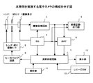
図1は本発明を実施する電子カメラの構成を示す図である。まず、同図について説明する。
図1に示す電子カメラ(以下、「本装置」と称する)は、被写体像を撮像素子2の受光面で結像させるレンズ1、レンズ1を経て本装置内に入射する光の光量を必要に応じて制限する絞り12、合焦のためのレンズ1の移動や適切な露出のための絞り12の調整のために用いられるレンズ・絞り駆動モータ8、レンズ・絞り駆動モータ8を制御するモータドライブ回路9、レンズ1によって結像された被写体像を電気信号に変換する撮像素子2、撮像素子2から出力される電気信号の増幅・サンプルホールド・アナログ/デジタル変換・輝度/色変換等の処理を行なう撮像処理回路3、映像信号処理に必要な基準信号(水平及び垂直同期信号等の各種パルス信号)を発生させるSG回路(パルス発生回路)4、不図示の映像記録・再生系へ被写体像を表現する映像信号を出力する映像記録・出力部5、撮像素子2の位置における被写体像の合焦の程度を評価するための高周波成分を映像信号における輝度信号から抽出するBPF(バンド・パス・フィルタ)回路6、CPU(中央処理装置)・ROM・RAM・タイマ(計時回路)等により構成される演算処理回路7、演算処理回路7からの指示に応じて撮影条件等の各種情報を表示する表示部13、押下操作で表現される撮影者からの映像信号の記録の指示を取得するレリーズSW(スイッチ)10、及び、操作によって表現される撮影者からの撮影条件の設定の変更の指示とその変更内容とを取得する操作部11を備えて構成されている。
【0020】
次に、図1に示す本装置の動作の概要について説明する。
まず、被写体光がレンズ1を経て本装置内に入射し、撮像素子の受光面上に被写体像として結像する。撮像素子2からの出力である被写体像を表現している電気信号である映像信号は、撮像処理回路3において増幅・サンプルホールド・アナログ/デジタル変換・輝度/色変換等の処理が施され、その後に映像記録・出力部5、BPF回路6、及び演算処理回路7へと送られる。
【0021】
映像記録・出力部5に送られた映像信号は不図示の映像記録・再生系の入力部へと出力される。
また、BPF回路6では、入力された映像信号における輝度(Y)信号の周波数成分のうちの高域の成分が抽出される。この高域成分の量の大小はその映像信号で表現される映像のコントラストの高低に対応するとみなすことが可能である。更に、BPF回路6では、この高域成分量を積分する処理が行なわれ、この積分値が演算処理回路7へと出力される。
【0022】
一般に、コントラストの高い映像ほどより正確に合焦がされているとみなすことができる。そこで、演算処理回路7はモータドライブ回路9を制御してレンズ・絞り駆動モータ8を駆動させてレンズ1を撮像素子2から見て前後に移動させ、そのときにBPF回路6より得られる前述した積分値が最大となったときのレンズ1の位置を合焦位置として設定する。以上の動作が「山登り方式」などと一般に称されているAFの一方式である。
【0023】
なお、以下の説明においては前述した高域成分の量の積分値を「AF評価値」と称することとする。
演算処理回路7では、上述したAFの処理が行なわれる一方で、撮像処理回路3から取得した映像信号における輝度(Y)信号を積分する処理、すなわち測光処理が行なわれる。そして、その測光の結果に基づき、撮像素子2における電荷蓄積時間、すなわちいわゆる素子シャッタにおけるシャッタ速度の設定制御、及びモータドライブ回路9を制御してレンズ・絞り駆動モータ8を駆動させて行なわれる絞り12の設定制御、つまりAEの処理が行なわれる。ここで、測光処理の結果である映像信号における輝度信号の積分値を「AE値」と称することとする。
【0024】
更に、演算処理回路7では、その映像信号における色差(C)信号に基づいたホワイトバランス(WB)処理も行なわれる。
ここで、演算処理部7は、SG回路4から取得される映像信号についての垂直同期(VD)信号及び水平同期(HD)信号を利用してAF、AE、WBの各制御処理の基礎となる情報を映像画面のうちのどの領域から取得するかをまず設定してから各制御処理を実行する。この設定は本装置のユーザによって変更できるように構成することも可能である。
【0025】
なお、演算処理回路7では、本装置のユーザによる操作部11への操作に応じた撮影条件の設定のための各種パラメータの変更の処理や、レリーズSW10に対する押下操作の受付及び繰り返しの押下操作における操作間隔時間の検出処理なども更に行なわれる。
【0026】
以下、本装置による速写撮影時において、レリーズSW10が押下操作されてから映像記録・出力部5より映像信号が出力されて不図示の映像記録・再生系で記録されるまでの、AE、AF、撮影(シャッタ)、記録の各処理(これらの処理を総称して「速写撮影処理」と称することとする)の手順についてフローチャートを参照しながら説明する。なお、これより説明する速写撮影処理は、いずれも演算処理回路7の構成要素であるCPUがROMに予め記録されている制御プログラムを読み出して実行することによって行なわれる。
【0027】
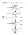
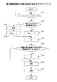
図2は速写撮影処理の手順の第一の例を示すフローチャートである。
まず、S101において、レリーズSW10への押下操作が検出されたか否かが判別され、この押下操作が検出されるまで、すなわちS101の判別結果がYesとなるまでこの判別処理が繰り返される。
【0028】
レリーズSW10への押下操作が検出されると計時のためのタイマが参照され、前ステップで検出された押下操作の直前にレリーズSW10に対して押下操作がなされたときからの経過時間が調べられる。そして、この経過時間が予め設定されている規定時間以内であったか否かがS102において判別され、この判別結果がYesならばS103に、NoならばS104に、それぞれ処理が進む。
【0029】
S103では、表示部13が制御され、上述したS102の判別結果がNoであったこと、すなわち、S101の処理において検出されたレリーズSW10への押下操作(以下、この押下操作を「今回の押下操作」と称することとする)がその直前のレリーズSW10への押下操作(以下、この押下操作を「前回の押下操作」と称することとする)から規定時間を過ぎた後に行なわれたことを示す表示がなされ、ユーザにその旨が告知される。なお、本装置に発音素子を設け、ユーザへのこの告知を表示部13への表示によって行なう代わりに音によって行なうようにしてもよい。
【0030】
上述したS103の処理を終えた後にはS106に処理が進む。
S104では前述したAEの処理が行なわれる。
S105では前述したAFの処理が行なわれる。
S106及びS107では撮影処理及び記録処理が実行され、このときに撮像素子2から出力される映像信号に対して撮像処理回路3で処理が施されて映像記録・出力部5より出力され、不図示の映像記録・再生系で記録される。
【0031】
以上までの手順が速写撮影処理の手順の第一の例である。この手順は、レリーズSW10に対する前回の押下操作から今回の押下操作までの経過時間が前述した規定時間以内であるような速写撮影が行なわれたときには、その経過時間の間で被写体の明るさや被写体と本装置との物理的な位置関係に大きな変化は生じないとみなし、AE及びAFについての新たな制御処理を行なわないようにしたものである。従って、このような場合にはこれらの制御処理が行なわれないので、それまでに設定されていたレンズ1の位置、絞り12の値、及び撮像素子2についてのシャッタ速度の設定が維持される。ここで、絞り12の値は、ユーザによって露出補正値が設定されている場合にはその補正値を反映させた値が維持され、また、本装置が調光のためのストロボを装備しているのであれば、そのストロボ発光の使用/使用についてもそれまでの設定が維持されるようにする。
【0032】
なお、上述した第一の例に関し、レリーズSW10に対する前回の押下操作によって行なわれる撮影に係る動作、すなわち被写体の撮影から画像信号の記録を完了するまでの一連の動作が完了する前に今回の押下操作がなされたときでも、この今回の押下操作の検出が行なえるようにするため、演算処理回路7のCPUは例えば割り込み処理によってレリーズSW10に対する押下操作の検出を行なうようにするとよい。
【0033】
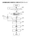
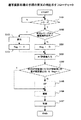
図3は速写撮影処理の手順の第二の例を示すフローチャートである。この図3を既に説明した図2のフローチャートと比較すると分かるように、図3に示す第二の例においてはS103の処理を終えた後には処理がS105に進む点で図2に示す第一の例と異なっている。つまり、この第二の例では、レリーズSW10に対する前回の押下操作から今回の押下操作までの経過時間が前述した規定時間以内であるような速写撮影が行なわれたときには、S104の処理であるAEについての新たな制御処理は行なわないものの、S105の処理であるAFについての処理については上述した経過時間の長短に拘らずに常に実行するようにしたものである。この例は、その経過時間の間で被写体の明るさには大きな変化は生じないが被写体と本装置との位置関係には大きな変化が生じ得ると予想される場合に有効である。
【0034】
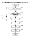
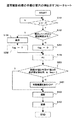
図4は速写撮影処理の手順の第三の例を示すフローチャートである。この図4を既に説明した図3のフローチャートと比較すると分かるように、図4に示す第四の例においてはS104の処理であるAEの処理とS105の処理であるAFの処理との処理順が入れ替わっている点で図3に示す第二の例と異なっている。つまり、この第三の例では、レリーズSW10に対する前回の押下操作から今回の押下操作までの経過時間が前述した規定時間以内であるような速写撮影が行なわれたときには、S105の処理であるAFについての新たな制御処理は行なわないものの、S104の処理であるAEについての処理については上述した経過時間の長短に拘らずに常に実行するようにしたものである。この例は、その経過時間の間で被写体と本装置との位置関係には大きな変化は生じないが被写体の明るさには大きな変化が生じ得ると予想される場合に有効である。
【0035】
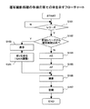
図5は速写撮影処理の手順の第四の例を示すフローチャートである。
図5において、S101からS103にかけての処理は図2に示した第一の例におけるものと同様である。但し、S102の判別処理の結果がNoのときには処理がS201に進み、また、S103の処理を終えた後には処理がS202に進む。
【0036】
S201ではフラグflagを「0」にセットし、その後はS104に処理が進む。
S202ではフラグflagを「1」にセットし、その後はS104に処理が進む。
【0037】
S104では他の例と同様のAEの処理が行なわれ、その後はS203に処理が進む。
S203では、上述したS104のAEの処理において得られたAE値と、レリーズSW10に対する前回の押下操作の際に実行されたAEの処理において得られたAE値との差が予め設定されている規定値以下であり、且つ、前述したフラグflagが「1」にセットされているか否かが判別される。この判別処理は、レリーズSW10に対する前回の押下操作から今回の押下操作までの経過時間が前述した規定時間以内であるか否かを判別しているのと等値である。そして、この判別結果が両者ともYesである以外のとき、すなわちいずれか若しくは両者ともNoのときには、S105において他の例と同様のAEの処理が行なわれる。なお、レリーズSW10に対する前回の押下操作の際に実行されたAEの処理において、その際に得られたAE値は演算処理回路7の有するRAMに保存しておくようにする。
【0038】
その後、S106及びS107では他の例と同様の撮影処理及び記録処理が実行される。
以上までの手順が速写撮影処理の手順の第四の例である。この手順は、レリーズSW10に対する前回の押下操作と今回の押下操作とにおけるAE値の変化が調べられ、前回の押下操作から今回の押下操作までの経過時間が前述した規定時間以内であるような速写撮影が行なわれたときにこのAE値が前述した規定値以内でしか変化していないのであれば、その経過時間の間で被写体の状態に大きな変化は生じていないとみなし、AFについての新たな制御処理を行なわないようにしたものである。
【0039】
図6は速写撮影処理の手順の第五の例を示すフローチャートである。この図6を既に説明した図5のフローチャートと比較すると分かるように、図6に示す第五の例におけるS301及びS302の処理が図5に示す第四の例におけるS104及びS203の処理と入れ替わっている点が図6と図5との違いである。以下、この異なる部分についてのみ説明する。
【0040】
S301では、AFの処理のうちのAF評価値を取得する処理のみが行なわれる。
ここで、S302において、上述したS105の処理において得られたAF評価と、レリーズSW10に対する前回の押下操作の際に実行されたAFの処理において得られたAF評価値との差が予め設定されている規定値以下であり、且つ、S201若しくはS202の処理によってセットされるフラグflagが「1」にセットされているか否かが判別される。この判別処理は、レリーズSW10に対する前回の押下操作から今回の押下操作までの経過時間が前述した規定時間以内であるか否かを判別するのと等値である。そして、この判別結果が両者ともYesである以外のとき、すなわちいずれか若しくは両者ともNoのときには、S105において、S301の処理で取得されたAF評価値に基づくAFの処理が他の例と同様に行なわれる。
【0041】
なお、レリーズSW10に対する前回の押下操作の際に実行されたAFの処理において、その際に得られたAF評価値は演算処理回路7の有するRAMに保存しておくようにする。
以上の処理が速写撮影処理の手順の第五の例において実行される。この手順は、レリーズSW10に対する前回の押下操作と今回の押下操作とにおけるAF評価値の変化が調べられ、前回の押下操作から今回の押下操作までの経過時間が前述した規定時間以内であるような速写撮影が行なわれたときにこのAF評価値が前述した規定値以内でしか変化していないのであれば、その経過時間の間で被写体の状態に大きな変化が生じていないとみなし、AFについての新たな制御処理を行なわないようにしたものである。なお、この例においては、AEの処理は上述した経過時間の長短に拘らずに行なわないので、レリーズSW10に対する前回の押下操作時に実行されるAEの処理の処理結果がそのまま維持される。
【0042】
図7は速写撮影処理の手順の第六の例を示すフローチャートである。この図7を既に説明した図5のフローチャートと比較すると分かるように、図7に示す第六の例におけるS401の処理が図5に示す第四の例におけるS105の処理と入れ替わっている点が図7と図5との違いである。
【0043】
この異なる部分についてのみ説明すると、S401では、レンズ1の可動範囲を制限して前述したAFの処理が行なわれる。
ここで、レンズ1の可動範囲を制限して行なわれるAFの処理について、図8を用いて説明する。
【0044】
図8に示すグラフは撮像素子2を基準としたときのレンズ1の位置に基づくAF評価値の変化の一例を表現したものであり、本実施例において採用している前述した山登り方式のAFにおいては、このグラフの山型のカーブの頂上に対応するレンズ1の位置を合焦位置とする。ここで、レンズ1の可動範囲を制限して行なわれるAFの処理は、同図に▲1▼として示しているようなレンズ1の通常の可動範囲のうち、▲2▼として示しているような可動範囲に限定してAF評価値を取得し、その可動範囲内で取得されるAF評価値の最大値を探索してレンズ1の合焦位置を決定するというものである。これは、レリーズSW10に対する前回の押下操作から今回の押下操作までの経過時間が前述した規定時間以内であるような速写撮影が行なわれたときにAE値が前述した規定値以内でしか変化していないのであれば被写体と本装置との物理的な位置関係に大きな変化は生じていないとみなせるから、▲1▼のようなレンズ1の通常の可動範囲の全てを対象とせずに▲2▼のようなレンズ1の可動範囲についてのみを対象としてAFの処理を行なっても合焦位置を正しく見つけ出すことができるとの考えに基づくものである。このようにレンズ1の可動範囲を制限してAFの処理を行なうと、AFの処理のための処理時間が短縮される効果が得られる。
【0045】
図9は速写撮影処理の手順の第七の例を示すフローチャートである。この図9を既に説明した図2のフローチャートと比較すると分かるように、図9に示す第七の例においてはS103の処理を終えた後に、S501の処理を行なってから処理がS105に進む点で図2に示す第一の例と異なっている。
【0046】
この異なる部分についてのみ説明すると、S501では、モータドライブ回路9に指示が与えられてレンズ・絞り駆動モータ8が制御され、絞り12を絞る動作が行なわれる。
以上の処理が速写撮影処理の手順の第七の例において実行される。この手順は、レリーズSW10に対する前回の押下操作から今回の押下操作までの経過時間が前述した規定時間以内であるような速写撮影が行なわれたときには、被写体と本装置との物理的な位置関係に大きな変化は生じないとみなし、絞り12を絞ることで被写界深度を深くしてその位置関係の変化による合焦位置のズレを解消させるというものである。
【0047】
なお、絞り12を絞ることによる光量の減少の問題を補償するために、撮像素子2から出力される映像信号に対して映像処理回路3で施される増幅処理における増幅度を光量の減少度に応じて増加させるとよい。また、増幅度を増加させる代わりに、撮像素子2についてのシャッタ速度の設定を変更して遅いシャッタ速度とすることでも光量の減少の問題は補償できる。
【0048】
以上までに説明した速写撮影処理のいずれかが演算処理回路7の有するCPUで行なわれることによって、図1に示す本装置で本発明が実施される。
なお、本発明は上述した実施例での実施に限定されるものではなく、種々の改良・変更が可能である。例えば、AFの方式は上述した山登り方式に限定されずいわゆるTTL位相差方式や赤外線等を利用するアクティブ方式などを採用するカメラで本発明を実施することは可能であり、また、フィルム上に被写体像を記録する銀塩写真の撮影を行なういわゆる銀塩カメラで本発明を実施することもできる。
【0053】
【発明の効果】
以上のように、本発明によれば、速写撮影におけるレリーズタイムラグの問題が軽減されるという効果を奏する。
【図面の簡単な説明】
【図1】本発明を実施する電子カメラの構成を示す図である。
【図2】速写撮影処理の手順の第一の例を示すフローチャートである。
【図3】速写撮影処理の手順の第二の例を示すフローチャートである。
【図4】速写撮影処理の手順の第三の例を示すフローチャートである。
【図5】速写撮影処理の手順の第四の例を示すフローチャートである。
【図6】速写撮影処理の手順の第五の例を示すフローチャートである。
【図7】レンズの可動範囲を制限して行なわれるAFの処理を説明する図である。
【図8】速写撮影処理の手順の第六の例を示すフローチャートである。
【図9】速写撮影処理の手順の第七の例を示すフローチャートである。
【符号の説明】
1 レンズ
2 撮像素子
3 映像処理回路
4 SG回路(パルス発生回路)
5 映像記録・出力部
6 BPF回路
7 演算処理回路
8 レンズ・絞り駆動モータ
9 モータドライブ回路
10 レリーズSW
11 操作部
12 絞り
13 表示部[0001]
BACKGROUND OF THE INVENTION
The present invention relates to a technique used for a camera, and more particularly to a technique for improving the performance of rapid shooting.
[0002]
[Prior art and problems to be solved by the invention]
One technique for taking multiple shots in a short time using a camera is a method called rapid-shooting. In contrast to so-called continuous shooting, in which rapid shooting is performed continuously while the release button is pressed by the photographer, the release button is pressed once by repeatedly pressing the release button. One shooting is performed for each operation.
[0003]
By the way, many recent cameras are equipped with an automatic exposure setting function (hereinafter referred to as “AE”) and an automatic focusing function (hereinafter referred to as “AF”). If this AE or AF is used in continuous shooting, the AE / AF functions when the release button is pressed, and during continuous shooting, that is, when the release button is pressed, unless the photographer instructs otherwise. The shooting conditions such as exposure, focus, and shutter speed determined in the above are maintained. On the other hand, AE / AF functions every time the release button is pressed in the rapid shooting. Therefore, taking into consideration that the brightness of the subject, the distance between the subject and the camera, etc. may change during the shooting, the rapid shooting has a higher control result by AE / AF than the continuous shooting. It can be said that it can be used appropriately.
[0004]
However, a certain amount of time is required until the shooting conditions are appropriately set in the camera by AE / AF. This time is also referred to as a release time lag. Due to this release time lag, the time responsiveness of AE / AF becomes a problem in high-speed shooting in which shooting is performed many times in a short time.
[0005]
As a technique for reducing the problem of the release time lag in the time-lapse photography, for example, there is a technique disclosed in the following publication.
1. JP, 8-76169, A Focus adjustment lens is previously set to the hyperfocal distance, and if the aperture obtained from the photometric result is larger than a predetermined value, the object field of the lens set to the hyperfocal distance Shoot the subject at depth.
2. When the release button is "pressed at once", shooting of the subject is performed with the display operation of shooting information such as exposure value and focus adjustment information omitted.
3. When the release priority mode is selected, the subject is immediately photographed in accordance with the operation of the release button regardless of the focus state.
[0006]
It is an object of the present invention to reduce the problem of the release time lag in rapid shooting by a method different from the technique described above.
[0007]
[Means for Solving the Problems]
A camera according to one aspect of the present invention includes an imaging unit that captures an image of a subject and obtains an image signal representing the image of the subject, and a photometric unit that performs photometric processing based on the image signal obtained by the imaging unit. An instruction means for instructing to start the photographing; and a focus of the lens for forming the subject image of the subject in accordance with the instruction for starting the photographing made by the instruction means at a position suitable for the photographing of the subject A focus control means for performing control to focus on the first and a first instruction for starting the photographing performed by the instruction means, and a first instruction for starting the photographing performed by the instruction means following the first instruction. detecting means for detecting an elapsed time until the second instruction, the elapsed time detected by said detecting means is not more than the prescribed time, and the second instruction is executed by said instruction means The first case where the change of the photometric processing result in the photometric means at the time from when the first instruction is given by the indicating means is within a prescribed value; and Determining means for determining the second case, which is a case other than the case, and at the time of rapid shooting, the focusing control means is configured so that the result of the determination by the determining means is the first case. In some cases, control for focusing the focus is not performed, and when the result of the determination by the determination means is the second case, the focus is controlled so that the movable range of the lens position is limited. to solve the aforementioned problems with the structure described and performed.
[0017]
Note that the camera according to the present invention described above may be configured to further include notification means for notifying information relating to the elapsed time .
[0018]
DETAILED DESCRIPTION OF THE INVENTION
Hereinafter, embodiments of the present invention will be described with reference to the drawings. Here, an example will be described in which the present invention is implemented in a so-called electronic camera that records a subject image on an electronic recording medium such as a memory.
[0019]
FIG. 1 is a diagram showing the configuration of an electronic camera that implements the present invention. First, the figure will be described.
The electronic camera shown in FIG. 1 (hereinafter referred to as “this apparatus”) requires a
[0020]
Next, an outline of the operation of the apparatus shown in FIG. 1 will be described.
First, subject light enters the apparatus through the
[0021]
The video signal sent to the video recording /
Further, the BPF circuit 6 extracts a high frequency component from the frequency components of the luminance (Y) signal in the input video signal. It can be considered that the amount of the high frequency component corresponds to the contrast level of the video represented by the video signal. Further, in the BPF circuit 6, processing for integrating the high frequency component amount is performed, and this integration value is output to the
[0022]
In general, it can be considered that an image with higher contrast is more accurately focused. Therefore, the
[0023]
In the following description, the above-described integrated value of the amount of the high frequency component is referred to as “AF evaluation value”.
In the
[0024]
Further, the
Here, the
[0025]
Note that the
[0026]
Hereinafter, during the time-lapse shooting by this apparatus, from the time when the
[0027]
FIG. 2 is a flowchart showing a first example of the procedure for the rapid shooting processing.
First, in S101, it is determined whether or not a pressing operation on the
[0028]
When a pressing operation on the
[0029]
In S103, the
[0030]
After the process of S103 described above is completed, the process proceeds to S106.
In S104, the AE process described above is performed.
In S105, the AF process described above is performed.
In S106 and S107, photographing processing and recording processing are executed. At this time, the video signal output from the imaging device 2 is processed by the imaging processing circuit 3 and output from the video recording /
[0031]
The procedure so far is the first example of the procedure for the rapid shooting process. In this procedure, when a rapid shooting is performed such that the elapsed time from the previous pressing operation to the
[0032]
In addition, regarding the first example described above, the current pressing operation is completed before the operation related to the shooting performed by the previous pressing operation on the
[0033]
FIG. 3 is a flowchart showing a second example of the procedure of the rapid shooting processing. As can be seen by comparing this FIG. 3 with the flowchart of FIG. 2 already described, in the second example shown in FIG. 3, the first process shown in FIG. It is different from the example. In other words, in this second example, when a rapid shooting is performed such that the elapsed time from the previous pressing operation to the
[0034]
FIG. 4 is a flowchart showing a third example of the procedure for the rapid shooting processing. As can be seen by comparing FIG. 4 with the flowchart of FIG. 3 already described, in the fourth example shown in FIG. 4, the processing order of the AE process that is the process of S104 and the AF process that is the process of S105 is the same. This is different from the second example shown in FIG. In other words, in this third example, when the rapid shooting is performed such that the elapsed time from the previous pressing operation to the
[0035]
FIG. 5 is a flowchart showing a fourth example of the procedure of the rapid shooting processing.
In FIG. 5, the processing from S101 to S103 is the same as that in the first example shown in FIG. However, when the result of the determination process in S102 is No, the process proceeds to S201, and after the process in S103 is completed, the process proceeds to S202.
[0036]
In S201, the flag flag is set to “0”, and then the process proceeds to S104.
In S202, the flag flag is set to “1”, and then the process proceeds to S104.
[0037]
In S104, the same AE process as in the other examples is performed, and thereafter, the process proceeds to S203.
In S203, the difference between the AE value obtained in the AE process in S104 described above and the AE value obtained in the AE process executed at the time of the previous pressing operation on the
[0038]
Thereafter, in S106 and S107, the same photographing process and recording process as in the other examples are executed.
The procedure so far is the fourth example of the procedure for the rapid shooting process. In this procedure, a change in the AE value between the previous pressing operation and the current pressing operation with respect to the
[0039]
FIG. 6 is a flowchart showing a fifth example of the procedure of the rapid shooting processing. As can be seen by comparing FIG. 6 with the flowchart of FIG. 5 already described, the processing of S301 and S302 in the fifth example shown in FIG. 6 is replaced with the processing of S104 and S203 in the fourth example shown in FIG. This is the difference between FIG. 6 and FIG. Only this different part will be described below.
[0040]
In S301, only the process of acquiring the AF evaluation value in the AF process is performed.
Here, in S302, a difference between the AF evaluation obtained in the process of S105 described above and the AF evaluation value obtained in the AF process executed at the time of the previous pressing operation on the
[0041]
In the AF process executed at the time of the previous pressing operation on the
The above processing is executed in the fifth example of the procedure of the rapid shooting processing. In this procedure, the change in the AF evaluation value between the previous pressing operation and the current pressing operation with respect to the
[0042]
FIG. 7 is a flowchart showing a sixth example of the procedure of the rapid shooting processing. As can be seen by comparing FIG. 7 with the flowchart of FIG. 5 already described, the processing of S401 in the sixth example shown in FIG. 7 is replaced with the processing of S105 in the fourth example shown in FIG. 7 is different from FIG.
[0043]
Only this different part will be described. In S401, the above-described AF processing is performed with the movable range of the
Here, AF processing performed by limiting the movable range of the
[0044]
The graph shown in FIG. 8 represents an example of a change in the AF evaluation value based on the position of the
[0045]
FIG. 9 is a flowchart showing a seventh example of the procedure of the rapid shooting processing. As can be seen by comparing FIG. 9 with the flowchart of FIG. 2 described above, in the seventh example shown in FIG. 9, after the process of S103 is completed, the process proceeds to S105 after performing the process of S501. This is different from the first example shown in FIG.
[0046]
Only this different part will be described. In S501, an instruction is given to the motor drive circuit 9, the lens / diaphragm drive motor 8 is controlled, and an operation of narrowing the diaphragm 12 is performed.
The above process is executed in the seventh example of the procedure of the rapid shooting process. This procedure is based on the physical positional relationship between the subject and the apparatus when a rapid shooting is performed such that the elapsed time from the previous pressing operation to the
[0047]
Note that, in order to compensate for the problem of a decrease in the amount of light due to the stop 12 being reduced, the amplification degree in the amplification process performed by the video processing circuit 3 on the video signal output from the image sensor 2 is changed to the reduction amount of the light amount. It should be increased accordingly. Further, the problem of reduction in the amount of light can also be compensated by changing the shutter speed setting for the image sensor 2 to a slow shutter speed instead of increasing the amplification degree.
[0048]
The present invention is implemented in the present apparatus shown in FIG. 1 by performing any of the rapid-shooting processes described above by the CPU of the
In addition, this invention is not limited to implementation in the Example mentioned above, A various improvement and change are possible. For example, the AF method is not limited to the above-described hill-climbing method, and the present invention can be implemented with a camera that employs a so-called TTL phase difference method, an active method using infrared rays, or the like. The present invention can also be implemented with a so-called silver salt camera that takes a silver salt photograph for recording an image.
[0053]
【The invention's effect】
As described above , according to the present invention , there is an effect that the problem of the release time lag in rapid shooting is reduced.
[Brief description of the drawings]
FIG. 1 is a diagram showing the configuration of an electronic camera that implements the present invention.
FIG. 2 is a flowchart showing a first example of a procedure for rapid shooting processing;
FIG. 3 is a flowchart illustrating a second example of a procedure for rapid shooting processing;
FIG. 4 is a flowchart illustrating a third example of a procedure for rapid shooting processing;
FIG. 5 is a flowchart illustrating a fourth example of a procedure for rapid shooting processing;
FIG. 6 is a flowchart illustrating a fifth example of a procedure for rapid shooting processing;
FIG. 7 is a diagram for explaining AF processing performed by limiting a movable range of a lens.
FIG. 8 is a flowchart illustrating a sixth example of a procedure for rapid shooting processing;
FIG. 9 is a flowchart illustrating a seventh example of a procedure for rapid shooting processing;
[Explanation of symbols]
DESCRIPTION OF
5 Video Recording / Output Unit 6
11 Operation unit 12
Claims (2)
前記撮像手段が得た画像信号を基に測光処理を行なう測光手段と、
前記撮影を開始させる指示を行なう指示手段と、
前記指示手段により行なわれた前記撮影を開始させる指示に応じて前記被写体の被写体像を結像させるレンズの焦点を該被写体の撮影に適した位置に合焦させる制御を行なう合焦制御手段と、
前記指示手段により行なわれた前記撮影を開始させる第一の指示から該第一の指示に続いて該指示手段により行なわれる前記撮影を開始させる第二の指示までの経過時間を検出する検出手段と、
前記検出手段により検出された経過時間が規定時間以内であって、且つ、前記指示手段により前記第二の指示が行なわれたときにおける前記測光手段での測光処理の結果についての、該指示手段により前記第一の指示が行なわれたときにおけるものからの変化が、規定値以内である第一の場合と、該第一の場合以外の場合である第二の場合との判別を行う判別手段と、
を有し、
速写撮影時において、前記合焦制御手段は、前記判別手段による前記判別の結果が前記第一の場合であるときには、前記焦点を合焦させる制御を行なわず、該判別手段による前記判別の結果が前記第二の場合であるときには、前記焦点を合焦させる制御を、前記レンズの位置の可動範囲を制限して行なう、
ことを特徴とするカメラ。Imaging means for taking an image of an object and obtaining an image signal representing the image of the object;
Photometric means for performing photometric processing based on the image signal obtained by the imaging means;
Instruction means for giving an instruction to start the photographing;
A focus control means for controlling the focus of a lens for forming the subject image of the subject to a position suitable for the photographing of the subject in response to an instruction to start the photographing performed by the instruction means;
Detection means for detecting an elapsed time from a first instruction for starting the photographing performed by the instruction means to a second instruction for starting the photographing performed by the instruction means following the first instruction; ,
By the instruction means about the result of the photometric processing in the photometry means when the elapsed time detected by the detection means is within a prescribed time and the second instruction is given by the instruction means A discriminating means for discriminating between a first case where a change from when the first instruction is made is within a specified value and a second case which is a case other than the first case; ,
Have
At the time of rapid-shooting, the focus control means does not perform control to focus the focus when the determination result by the determination means is the first case, and the determination result by the determination means When it is the second case, the control for focusing the focal point is performed by limiting the movable range of the position of the lens .
A camera characterized by that.
Priority Applications (1)
| Application Number | Priority Date | Filing Date | Title |
|---|---|---|---|
| JP2001053368A JP4615744B2 (en) | 2001-02-28 | 2001-02-28 | camera |
Applications Claiming Priority (1)
| Application Number | Priority Date | Filing Date | Title |
|---|---|---|---|
| JP2001053368A JP4615744B2 (en) | 2001-02-28 | 2001-02-28 | camera |
Publications (2)
| Publication Number | Publication Date |
|---|---|
| JP2002258141A JP2002258141A (en) | 2002-09-11 |
| JP4615744B2 true JP4615744B2 (en) | 2011-01-19 |
Family
ID=18913838
Family Applications (1)
| Application Number | Title | Priority Date | Filing Date |
|---|---|---|---|
| JP2001053368A Expired - Fee Related JP4615744B2 (en) | 2001-02-28 | 2001-02-28 | camera |
Country Status (1)
| Country | Link |
|---|---|
| JP (1) | JP4615744B2 (en) |
Families Citing this family (1)
| Publication number | Priority date | Publication date | Assignee | Title |
|---|---|---|---|---|
| JP2011247970A (en) * | 2010-05-25 | 2011-12-08 | Sanyo Electric Co Ltd | Electronic camera |
Family Cites Families (9)
| Publication number | Priority date | Publication date | Assignee | Title |
|---|---|---|---|---|
| JPS58132735A (en) * | 1982-02-03 | 1983-08-08 | Canon Inc | Camera |
| JPS61130932A (en) * | 1984-11-30 | 1986-06-18 | Canon Inc | camera |
| JP2615818B2 (en) * | 1988-04-25 | 1997-06-04 | 株式会社ニコン | Camera operation control device |
| JPH0519160A (en) * | 1991-06-19 | 1993-01-29 | Olympus Optical Co Ltd | Range finder for camera |
| JPH07303205A (en) * | 1994-04-28 | 1995-11-14 | Canon Inc | Imaging device and imaging method thereof |
| JP3483370B2 (en) * | 1995-10-06 | 2004-01-06 | キヤノン株式会社 | Focus detection device, exposure control device, and camera |
| JPH09105855A (en) * | 1995-10-06 | 1997-04-22 | Canon Inc | Camera lens control device and interchangeable lens |
| JP3417845B2 (en) * | 1998-05-29 | 2003-06-16 | ペンタックス株式会社 | Lens movement control device |
| JP4404416B2 (en) * | 1998-10-16 | 2010-01-27 | Hoya株式会社 | Automatic focus adjustment device |
-
2001
- 2001-02-28 JP JP2001053368A patent/JP4615744B2/en not_active Expired - Fee Related
Also Published As
| Publication number | Publication date |
|---|---|
| JP2002258141A (en) | 2002-09-11 |
Similar Documents
| Publication | Publication Date | Title |
|---|---|---|
| JP5322783B2 (en) | IMAGING DEVICE AND CONTROL METHOD OF IMAGING DEVICE | |
| US9344621B2 (en) | Imaging device and control method for imaging device | |
| JP5635211B2 (en) | Imaging device | |
| JP4644883B2 (en) | Imaging device | |
| JP2007074388A (en) | Imaging apparatus and program thereof | |
| KR100871639B1 (en) | Camera and image processing method for camera | |
| US7609319B2 (en) | Method and apparatus for determining focusing position | |
| JP2010256824A (en) | Imaging device | |
| JP4727534B2 (en) | Imaging device | |
| JP2009157123A (en) | Imaging device | |
| JP5371474B2 (en) | Imaging apparatus, control method, and program | |
| JP2007233113A (en) | Ranging apparatus and method | |
| JP4615744B2 (en) | camera | |
| JP2002258344A (en) | Camera | |
| JP2003241066A (en) | Camera | |
| JP3562820B2 (en) | Automatic focusing device | |
| JP4855155B2 (en) | Imaging apparatus and imaging method using the same | |
| JP2004333924A (en) | Camera | |
| JP4847352B2 (en) | Imaging apparatus and control method thereof | |
| JP2007057974A (en) | Imaging device | |
| JP5418553B2 (en) | Imaging apparatus and imaging method using the same | |
| JP2003222787A (en) | Digital camera | |
| JP4537791B2 (en) | Apparatus and method for automatic focusing / exposure amount control of imaging system | |
| JP2005345877A (en) | Focus-detecting device and focus-detecting method | |
| JP2007212723A (en) | In-focus position determination method and apparatus |
Legal Events
| Date | Code | Title | Description |
|---|---|---|---|
| A621 | Written request for application examination |
Free format text: JAPANESE INTERMEDIATE CODE: A621 Effective date: 20071005 |
|
| A977 | Report on retrieval |
Free format text: JAPANESE INTERMEDIATE CODE: A971007 Effective date: 20100707 |
|
| A131 | Notification of reasons for refusal |
Free format text: JAPANESE INTERMEDIATE CODE: A131 Effective date: 20100803 |
|
| A521 | Request for written amendment filed |
Free format text: JAPANESE INTERMEDIATE CODE: A523 Effective date: 20100927 |
|
| TRDD | Decision of grant or rejection written | ||
| A01 | Written decision to grant a patent or to grant a registration (utility model) |
Free format text: JAPANESE INTERMEDIATE CODE: A01 Effective date: 20101019 |
|
| A01 | Written decision to grant a patent or to grant a registration (utility model) |
Free format text: JAPANESE INTERMEDIATE CODE: A01 |
|
| A61 | First payment of annual fees (during grant procedure) |
Free format text: JAPANESE INTERMEDIATE CODE: A61 Effective date: 20101021 |
|
| FPAY | Renewal fee payment (event date is renewal date of database) |
Free format text: PAYMENT UNTIL: 20131029 Year of fee payment: 3 |
|
| S531 | Written request for registration of change of domicile |
Free format text: JAPANESE INTERMEDIATE CODE: R313531 |
|
| R350 | Written notification of registration of transfer |
Free format text: JAPANESE INTERMEDIATE CODE: R350 |
|
| LAPS | Cancellation because of no payment of annual fees |