JP5371474B2 - Imaging apparatus, control method, and program - Google Patents
Imaging apparatus, control method, and program Download PDFInfo
- Publication number
- JP5371474B2 JP5371474B2 JP2009032868A JP2009032868A JP5371474B2 JP 5371474 B2 JP5371474 B2 JP 5371474B2 JP 2009032868 A JP2009032868 A JP 2009032868A JP 2009032868 A JP2009032868 A JP 2009032868A JP 5371474 B2 JP5371474 B2 JP 5371474B2
- Authority
- JP
- Japan
- Prior art keywords
- luminance
- image
- subject
- range
- aperture value
- Prior art date
- Legal status (The legal status is an assumption and is not a legal conclusion. Google has not performed a legal analysis and makes no representation as to the accuracy of the status listed.)
- Active
Links
- 238000003384 imaging method Methods 0.000 title claims description 73
- 238000000034 method Methods 0.000 title claims description 38
- 238000004364 calculation method Methods 0.000 claims description 38
- 230000003287 optical effect Effects 0.000 claims description 16
- 238000001514 detection method Methods 0.000 claims description 3
- 235000019557 luminance Nutrition 0.000 description 83
- 238000012545 processing Methods 0.000 description 57
- 230000006870 function Effects 0.000 description 29
- 238000009825 accumulation Methods 0.000 description 15
- 238000005259 measurement Methods 0.000 description 12
- 238000005375 photometry Methods 0.000 description 9
- 230000006835 compression Effects 0.000 description 5
- 238000007906 compression Methods 0.000 description 5
- 230000006837 decompression Effects 0.000 description 4
- 230000011514 reflex Effects 0.000 description 4
- 230000035945 sensitivity Effects 0.000 description 4
- 230000003247 decreasing effect Effects 0.000 description 2
- 238000011161 development Methods 0.000 description 2
- 238000010586 diagram Methods 0.000 description 2
- 230000006641 stabilisation Effects 0.000 description 2
- 238000011105 stabilization Methods 0.000 description 2
- 230000003044 adaptive effect Effects 0.000 description 1
- 238000006243 chemical reaction Methods 0.000 description 1
- 238000012937 correction Methods 0.000 description 1
- 238000011156 evaluation Methods 0.000 description 1
- 230000001771 impaired effect Effects 0.000 description 1
- 238000012544 monitoring process Methods 0.000 description 1
- 238000012552 review Methods 0.000 description 1
- 239000004065 semiconductor Substances 0.000 description 1
Images


Landscapes
- Exposure Control For Cameras (AREA)
- Viewfinders (AREA)
- Studio Devices (AREA)
Description
本発明は、電子ビューファインダ機能を有する撮像装置、その制御方法及びプログラムに関する。 The present invention relates to an imaging apparatus having an electronic viewfinder function, a control method thereof, and a program .
従来、動画モニタ機能を有する撮像装置が知られている。動画モニタ機能とは、撮像装置のモニタ(表示部)に被写体の撮影前の画像を表示する、いわゆるライブビュー機能である。この種の撮像装置では、撮像素子(CMOSイメージセンサ或いはCCDイメージセンサ等)により被写体の光学像を光電変換して得られた映像信号をデータ処理回路等で所定の処理を施した後、モニタに画像(動画)として表示する。 Conventionally, an imaging apparatus having a moving image monitoring function is known. The moving image monitor function is a so-called live view function for displaying an image of a subject before photographing on a monitor (display unit) of the imaging apparatus. In this type of imaging apparatus, a video signal obtained by photoelectrically converting an optical image of a subject by an imaging device (such as a CMOS image sensor or a CCD image sensor) is subjected to predetermined processing by a data processing circuit or the like, and is then applied to a monitor. Display as an image (movie).
撮像装置のモニタに表示される画像の露出は、映像信号が所定値となるように、3つの制御パラメータ(撮像素子に対する電荷の蓄積時間:Tv、絞り:Av、ISO感度:Sv)を切り換えることで制御されている。3つの制御パラメータの組み合わせは、撮像装置に記憶されているプログラム線図に基づき決定される。被写体の輝度Evの値が求まると、3つの制御パラメータの値から明るさBvの値が決まる。以下の式は、Evと、Bv、Tv、Av、Svとの関係式である。 The exposure of the image displayed on the monitor of the image pickup apparatus is switched between three control parameters (charge storage time for the image pickup element: Tv, aperture: Av, ISO sensitivity: Sv) so that the video signal becomes a predetermined value. It is controlled by. A combination of the three control parameters is determined based on a program diagram stored in the imaging apparatus. When the value of the luminance Ev of the subject is obtained, the value of the brightness Bv is determined from the values of the three control parameters. The following expression is a relational expression between Ev and Bv, Tv, Av, Sv.
Ev = Bv+Sv = Tv + Av
他方、撮像装置で絞りAvを制御することで露光量を制御する絞り駆動において、被写体の輝度Evの変化に対してヒステリシスを設けることで絞り値の変化を抑えるという機能に関する技術が提案されている(例えば、特許文献1参照)。
Ev = Bv + Sv = Tv + Av
On the other hand, there has been proposed a technique related to a function of suppressing a change in aperture value by providing a hysteresis with respect to a change in luminance Ev of a subject in aperture driving in which an exposure amount is controlled by controlling an aperture Av with an imaging device. (For example, refer to Patent Document 1).
ここで、ライブビュー機能を有する撮像装置において、ライブビュー時のプログラム線図を以下のように決定した場合を考える。即ち、高いISO感度でのノイズの増加、短い蓄積時間(高速Tv)でのフレーム間の連続性が損なわれることによる違和感、絞りAvの変化による画像の露光量や深度の変化、そして、駆動音などの問題を考慮して、図6に示すように決定したとする。 Here, let us consider a case where the program diagram at the time of live view is determined as follows in an imaging apparatus having a live view function. That is, an increase in noise at a high ISO sensitivity, a sense of incongruity due to loss of continuity between frames at a short accumulation time (high speed Tv), a change in image exposure amount and depth due to a change in aperture Av, and a driving sound Assume that the determination is made as shown in FIG.
図6において、上側の横軸と左側の縦軸は被写体の輝度Ev、下側の横軸は蓄積時間Tv、右側の縦軸は絞りAvを示す。右下向きの「くの字状」矢印は暗くなる変化を示し、左上向きの「くの字状」矢印は明るくなる変化を示す。図6のプログラム線図では、被写体の輝度Evが低輝度から高輝度に変化する場合は実線を選択し、高輝度から低輝度に変化する場合は2点鎖線を選択するものである。 In FIG. 6, the upper horizontal axis and the left vertical axis indicate the luminance Ev of the subject, the lower horizontal axis indicates the accumulation time Tv, and the right vertical axis indicates the aperture Av. The “arrow-shaped” arrow pointing downward to the right indicates a change that darkens, and the “arrow-shaped” arrow pointing upward to the left indicates a change that brightens. In the program diagram of FIG. 6, a solid line is selected when the luminance Ev of the subject changes from low luminance to high luminance, and a two-dot chain line is selected when the luminance Ev changes from high luminance to low luminance.
即ち、Ev4〜Ev8とEv8〜Ev12の輝度で絞りAvにヒステリシス(低輝度から高輝度に変化する場合に選択する実線と、高輝度から低輝度に変化する場合に選択する2点鎖線の経路が異なる特性)を設けている。 That is, there is a hysteresis in the aperture Av with the luminance of Ev4 to Ev8 and Ev8 to Ev12 (a solid line selected when changing from low luminance to high luminance, and a two-dot chain line selected when changing from high luminance to low luminance). Different characteristics).
例えば、図6において、被写体の輝度Evが低輝度から高輝度に変化する場合にはEv8を超えると絞り値を変更するのに対し、高輝度から低輝度に変化する場合にはEv8を下回っても絞り値を変更せず、Ev4を下回ることで絞り値を変更する。このように、被写体の輝度Evが低輝度から高輝度に変化する場合と高輝度から低輝度に変化する場合とで、絞り値を変化させる変化点となる輝度を異ならせることで、頻繁に絞り値が変化することを抑えることができる。 For example, in FIG. 6, when the luminance Ev of the subject changes from low luminance to high luminance, the aperture value is changed when it exceeds Ev8, whereas when the luminance Ev changes from high luminance to low luminance, it falls below Ev8. Also, the aperture value is not changed, and the aperture value is changed by falling below Ev4. In this way, the aperture is frequently changed by changing the luminance that becomes the changing point for changing the aperture value when the luminance Ev of the subject changes from low luminance to high luminance and when the subject changes from high luminance to low luminance. It can suppress that a value changes.
図7は、従来例に係る撮像装置の制御パラメータ演算処理(図6のプログラム線図におけるそれぞれの制御パラメータの値を決めるための概略の制御)を示すフローチャートである。 FIG. 7 is a flowchart showing control parameter calculation processing (schematic control for determining the value of each control parameter in the program diagram of FIG. 6) of the imaging apparatus according to the conventional example.
図7において、撮像装置の制御部は、制御パラメータ演算処理を開始すると(ステップS701)、次の値を取得する。即ち、前回の演算処理で算出された絞り値PreAvと、今回の演算処理を行う直前の被写体の輝度Evをそれぞれ取得する(ステップS702、ステップS703)。次に、制御部は、被写体の輝度Evが、前回の絞り値PreAvの連動範囲内にあるかどうかを確認し、絞り値を絞り値PreAvから変更する必要があるか否かを判定する(ステップS704)。ここで、連動範囲とは、図6のプログラム線図で水平方向の太線(太い実線、太い2点鎖線)で示す範囲である。 In FIG. 7, when the control unit of the imaging apparatus starts the control parameter calculation process (step S701), the next value is acquired. That is, the aperture value PreAv calculated in the previous calculation process and the luminance Ev of the subject immediately before the current calculation process are acquired (steps S702 and S703). Next, the control unit checks whether or not the luminance Ev of the subject is within the interlocking range of the previous aperture value PreAv, and determines whether or not the aperture value needs to be changed from the aperture value PreAv (step S1). S704). Here, the interlocking range is a range indicated by a horizontal thick line (thick solid line, thick two-dot chain line) in the program diagram of FIG.
被写体の輝度Evが連動範囲外の場合は、被写体の輝度Evが連動範囲内となるように制御パラメータ演算を行い、制御パラメータ(Tv、Av、Sv)の値を算出する(ステップS705)。被写体の輝度Evが連動範囲内の場合は、前回の絞り値PreAvに基づき制御パラメータ演算を行い、その他の制御パラメータ(Tv、Sv)の値を算出する(ステップS706)。 If the subject brightness Ev is outside the interlocking range, the control parameter calculation is performed so that the subject brightness Ev is within the interlocking range, and the values of the control parameters (Tv, Av, Sv) are calculated (step S705). When the luminance Ev of the subject is within the interlocking range, the control parameter calculation is performed based on the previous aperture value PreAv, and the values of the other control parameters (Tv, Sv) are calculated (step S706).
上述した従来の撮像装置において、ライブビュー開始時は主被写体に比べ主被写体以外がよりぼける現象を緩和するため、および焦点合わせの精度がはっきり分かるようにするために、絞り制御にヒステリシスのある輝度範囲では、開放側の絞りが選択される。すなわち、従来の撮像装置においてライブビューを開始する場合、絞り値Avは設定可能な最も開放される絞り値(設定可能な最も小さい絞り値)が設定される。 In the conventional imaging apparatus described above, the brightness with hysteresis in the aperture control is used to alleviate the phenomenon that other than the main subject is blurred compared to the main subject at the start of the live view and to clearly understand the focusing accuracy. In the range, the aperture on the open side is selected. That is, when the live view is started in the conventional imaging apparatus, the aperture value Av that is set to the most open aperture value (the smallest aperture value that can be set) is set.
しかし、従来は、上記のように開放側の絞りを選択するため、ライブビューを開始する時に例えば図6に示すEv7〜Ev8の輝度ではF1.8の絞りとなる。この場合、被写体の輝度が高輝度側に1段程度変化すると、すぐに絞り値が変化してしまう。その結果、絞り値の変化に伴い、深度の変化、音の変化、画像の輝度変化などが生じてしまい、操作者が違和感を持つという問題があった。 However, conventionally, since the aperture on the open side is selected as described above, when the live view is started, for example, the aperture is F1.8 at the luminance of Ev7 to Ev8 shown in FIG. In this case, when the luminance of the subject changes by about one step toward the high luminance side, the aperture value immediately changes. As a result, a change in depth, a change in sound, a change in luminance of an image, and the like occur with a change in aperture value, and there is a problem that the operator feels uncomfortable.
本発明は上記問題点を鑑みてなされたものであり、絞り値の変化を抑えることで操作者が感じる違和感を生じにくくすることを目的とする。 The present invention has been made in view of the above problems, and an object thereof is to make it difficult for an operator to feel a sense of discomfort by suppressing a change in aperture value.
上記目的を達成するために、本発明に係る撮像装置は、被写体の光学像を電気信号に変換する撮像素子と、前記撮像素子を用いて得られた画像を逐次表示することが可能な表示手段と、を備え、絞りを制御して前記撮像素子へ入射する光量を調整する撮像装置であって、前記被写体の輝度を算出する算出手段と、前記算出手段により算出された輝度が所定範囲にある場合に前記絞りの絞り値を変更する制御手段と、を有し、前記制御手段は、前記表示手段による前記画像の逐次表示の開始前と逐次表示中とで前記所定範囲を変更し、前記画像の逐次表示の開始前に前記被写体の輝度が前記所定範囲にある場合は前記画像の逐次表示の開始前に前記絞り値を変更することを特徴とする。 In order to achieve the above object, an imaging apparatus according to the present invention includes an imaging device that converts an optical image of a subject into an electrical signal, and display means that can sequentially display an image obtained using the imaging device. And an imaging device that controls the diaphragm to adjust the amount of light incident on the imaging device, the calculating unit calculating the luminance of the subject, and the luminance calculated by the calculating unit is within a predetermined range Control means for changing the aperture value of the aperture in a case where the control means changes the predetermined range before and after the sequential display of the images by the display means and during the sequential display, If the luminance of the subject is within the predetermined range before the start of sequential display, the aperture value is changed before the start of sequential display of the images.
本発明によれば、絞り値の変化に伴う深度の変化、音の変化、画面の輝度変化などの操作者が感じる違和感を生じにくくすることができる。 According to the present invention, it is possible to make it difficult for an operator to feel a sense of discomfort such as a change in depth, a change in sound, and a change in screen brightness due to a change in aperture value.
以下、本発明の実施の形態を図面に基づいて説明する。 Hereinafter, embodiments of the present invention will be described with reference to the drawings.
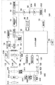
図1は、本発明の実施の形態に係る撮像装置の構成を示すブロック図である。 FIG. 1 is a block diagram showing a configuration of an imaging apparatus according to an embodiment of the present invention.
図1において、撮像装置100は、デジタルカメラとして構成されており、記録媒体200とレンズユニット300が着脱可能に装着されている。撮像装置100は、シャッタ12、撮像素子14、画像処理回路20、画像表示部29、測距制御部42、測光制御部44、システム制御部50等を備えている。記録媒体200は、記録部202等を備えている。レンズユニット300は、撮影レンズ310、絞り312、レンズシステム制御部350等を備えている。尚、図1の構成で本発明の要旨に直接関係しない構成については説明を簡略化または省略する。
In FIG. 1, an
シャッタ12は、撮像素子14への露光量を制御する。撮像素子14は、被写体の光学像を電気信号に変換する。ミラー130、132は、レンズユニット300の撮影レンズ310に入射した光線を、一眼レフ方式により光学ファインダ104に導く。尚、ミラー130は、クイックリターンミラー、ハーフミラーのどちらの構成でもよい。撮影時においては、撮影レンズ310に入射した光線は、絞り312、レンズマウント306、撮像装置100のレンズマウント106、ミラー130、シャッタ12を介して光学像として撮像素子14に結像される。ミラー130がクイックリターンミラーの場合、撮影時にはミラー130は待避位置に移動するため、撮影レンズ310に入射した光線はミラー130を介することなく撮像素子14に結像される。
The
A/D変換器16は、撮像素子14から出力されるアナログ信号をデジタル信号にA/D変換する。タイミング発生回路18は、メモリ制御回路22及びシステム制御部50により制御され、撮像素子14、 A/D変換器16、システム制御50にクロック信号や制御信号を供給する。
The A / D converter 16 A / D converts the analog signal output from the
画像処理回路20は、 A/D変換器16或いはメモリ制御回路22から出力されるデータに対して所定の画素補間処理や色変換処理を行う。また、画像処理回路20は、連続する2つの画像を使ってフレーム間の相関のズレ量とその方向を求め、必要に応じて、撮像した画像データを用いて所定の演算処理を行う。また、画像処理回路20は、撮像素子14から出力される電気信号をA/D変換器16でA/D変換したデータに基づき被写体の輝度を算出する。
The
また、画像処理回路20は、得られた演算結果に基づいて、システム制御部50がシャッタ制御部40、測距制御部42に対して制御を行うTTL(スルー・ザ・レンズ)方式のAF(オートフォーカス)処理、AE(自動露出)処理を行う。更に、画像処理回路20は、撮像した画像データを用いて所定の演算処理を行い、得られた演算結果に基づいてTTL方式のAWB(オートホワイトバランス)処理も行う。
In addition, the
尚、本実施の形態では、測距制御部42及び測光制御部44を専用に備える構成としているため、光学ファインダ104の使用時は、測距制御部42及び測光制御部44を用いてAF処理、AE処理、EF(フラッシュ調光)処理の各処理を行う。また、電子ビューファインダ(以下、EVFとする)の使用時は、システム制御部50の制御により画像処理回路20を用いたAF処理、AE処理、EF処理の各処理を行うように自動で切り換える。
In the present embodiment, since the distance
メモリ制御回路22は、A/D変換器16、タイミング発生回路18、画像処理回路20、画像表示メモリ24、D/A変換器26、メモリ30、圧縮・伸長回路32を制御する。タイミング発生回路18の制御信号は、システム制御部50にも入力されている。これにより、システム制御部50は撮像制御のタイミングを知ることができる。A/D変換器16から出力されるデータは、画像処理回路20及びメモリ制御回路22を介して或いは直接メモリ制御回路22を介して、画像表示メモリ24或いはメモリ30に書き込まれる。
The
画像表示部29は、例えばTFT LCDから構成されており、撮像装置100で撮影した被写体の画像(静止画、動画)の表示を行う。撮像装置100においては、被写体の撮影前画像を画像表示部29或いは画像出力部を介して外部のモニタ(不図示)に逐次表示することで、EVFとして機能させることができる。尚、本実施の形態では、撮像装置100は操作部70への操作によって、画像表示部29或いは外部のモニタをEVFとして使用するライブビュー機能を実行するものとする。
The
メモリ30は、撮影した静止画像や動画像を格納するものであり、所定枚数の静止画像や所定時間の動画像を格納するのに十分な記憶量を備えている。また、メモリ30は、システム制御部50の作業領域としても使用することが可能である。圧縮・伸長回路32は、適応離散コサイン変換(ADCT)等により画像データを圧縮/伸長する回路であり、メモリ30に格納された画像データを読み込んで圧縮処理或いは伸長処理を行い、処理を終えた画像データをメモリ30に書き込む。
The
シャッタ制御部40は、測光制御部44からの測光情報に基づいて、レンズユニット300の絞り312を制御する絞り制御部340と連携しながらシャッタ12を制御する。測距制御部42は、AF処理を行う。撮影レンズ310に入射した光線を一眼レフ方式により、絞り312、レンズマウント306、106、ミラー130、不図示の測距用サブミラーを介して測距制御部42に入射させることで、光学像として結像された画像の合焦状態を測定する。
The shutter control unit 40 controls the
測光制御部44は、AE処理を行う。撮影レンズ310に入射した光線を一眼レフ方式により、絞り312、レンズマウント306、106、ミラー130、132、不図示の測光用レンズを介して測光制御部44に入射させることで、光学像として結像された画像の露出状態を測定する。
The
尚、EVFの使用時においては、撮像素子14により撮像した画像データを画像処理回路20により演算した演算結果に基づき、システム制御部50が以下の制御を行う。シャッタ制御手段40、絞り制御部340、測距制御部342に対して制御を行うビデオTTL方式を用いて露出制御及びAF制御を行う。
When the EVF is used, the
この場合、測距制御部42による測定結果と、撮像素子14により撮像した画像データを画像処理回路20により演算した演算結果とを共に用いて、AF制御を行っても構わない。また、測光制御部44による測定結果と、撮像素子14により撮像した画像データを画像処理回路20により演算した演算結果とを共に用いて、露出制御を行っても構わない。
In this case, the AF control may be performed by using both the measurement result by the distance
システム制御部50は、撮像装置100の全体を制御するものであり、プログラム(画像制御の制御パラメータの値を演算するアルゴリズム)に基づき、図2のフローチャートに示す処理を実行する。システム制御部50は、EVFで表示する被写体の撮影前画像の明るさを制御するための複数のプログラム線図(画像制御の制御パラメータの値を演算するためのアルゴリズム)を格納している。本実施の形態では、複数のプログラム線図としては、図3に示す通常のプログラム線図、図4に示すライブビュー開始時に使用されるプログラム線図、図5に示す短い蓄積時間(高速Tv)まで選択可能な場合に使用されるプログラム線図などがある。詳細は後述する。
The
また、システム制御部50は、画像処理回路20により算出された被写体の輝度を画像制御の制御パラメータの値に変換する。また、システム制御部50は、ライブビュー開始時とライブビュー中とで、画像制御の制御パラメータ演算処理において、レンズユニット300の絞り312を変化させる変化点となる輝度が異なるように制御を行う。また、システム制御部50は、ライブビュー中において、画像処理回路20により被写体の動きを検知した結果に基づき、プログラム線図で設定可能な蓄積時間Tvを切り換える制御を行う。
Further, the
表示部54は、システム制御部50でのプログラムの実行に応じて、動作状態やメッセージ等を文字・画像で表示出力/音声出力する。表示部54は、例えばLCD・LED・発音素子等の組み合わせから構成され、撮像装置100の操作部近辺の視認し易い位置に単数(或いは複数)設置されている。また、表示部54は、その一部の機能が光学ファインダ104内に設置されている。
The
シャッタスイッチSW1・62は、シャッタボタン(不図示)の操作途中でONとなり、AF処理、AE処理、AWB処理、EF処理等の動作開始を指示する。 The shutter switches SW1 and 62 are turned on during the operation of a shutter button (not shown), and instruct to start operations such as AF processing, AE processing, AWB processing, and EF processing.
シャッタスイッチSW2・64は、シャッタボタンの操作完了でONとなり、一連の処理(露光処理、現像処理、記録処理)の動作開始を指示する。露光処理では、撮像素子14から読み出した信号をA/D変換器16、メモリ制御回路22を介してメモリ30に画像データとして書き込む。現像処理では、画像処理回路20やメモリ制御回路22での演算を用いて行う。記録処理では、メモリ30から画像データを読み出し、圧縮・伸長回路32で圧縮を行い、記録媒体200に書き込む。
The shutter switches SW2 and 64 are turned on when the operation of the shutter button is completed, and instruct the operation start of a series of processing (exposure processing, development processing, recording processing). In the exposure process, the signal read from the
操作部70は、メニューボタン、セットボタン、メニュー選択などに用いる十字ボタン、クイックレビューON/OFFスイッチ、圧縮モードスイッチ、再生スイッチ、AFモード設定スイッチ等を備える。また、操作部70は、ライブビュー機能の開始を指示するライブビュースイッチを備えていて、光学ファインダ使用時にライブビュースイッチを操作することでEVFが使用可能となり、ライブビュー機能が実行される。
The
尚、ライブビュー機能の開始を指示するための専用のスイッチを備えるのではなく、他の構成によりライブビュー機能の開始を指示しても構わない。例えば、複数の撮影モードから任意の撮影モードを選択する撮影モード選択スイッチを備え、ライブビューモード或いは動画撮影モードが選択されることでライブビュー機能の開始を指示する構成であってもよい。 Note that, instead of providing a dedicated switch for instructing the start of the live view function, the start of the live view function may be instructed by another configuration. For example, a configuration may be provided in which a shooting mode selection switch for selecting an arbitrary shooting mode from a plurality of shooting modes is provided, and the start of the live view function is instructed when the live view mode or the moving image shooting mode is selected.
インタフェース部90は、撮像装置100と記録媒体200との間のインタフェースを司る。コネクタ92は、記録媒体200のコネクタ206と接続され、撮像装置100を記録媒体200に電気的に接続する。
The
光学ファインダ104は、撮影レンズ310に入射した光線を、一眼レフ方式により、絞り312、レンズマウント306、106、ミラー130、132を介して導き、光学像として結像し表示する。これにより、画像表示部29をEVFとして使用せずに、光学ファインダ104のみを用いた撮影が可能である。また、光学ファインダ104内には、表示部54の一部の機能(例えば、合焦表示、手振れ警告表示、フラッシュ充電表示、シャッタスピード表示、絞り値表示、露出補正表示等)が設置されている。
The
インタフェース部120は、レンズマウント106内において撮像装置100をレンズユニット300に接続する。コネクタ122は、レンズユニット300のコネクタ322と接続され、撮像装置100をレンズユニット300に電気的に接続する。撮像装置100のレンズマウント106及び或いはコネクタ122にレンズユニット300が装着されているか否かは、接続検知部(不図示)で検知する。
The
記録媒体200は、例えばメモリカード或いはハードディスクから構成される。記録媒体200は、半導体メモリ或いは磁気ディスクから構成される記録部202、撮像装置100とのインタフェースを司るインタフェース部204、撮像装置100と接続を行うコネクタ206を備えている。
The
レンズユニット300は、交換レンズタイプであり、撮影レンズ310、絞り312、レンズマウント306、インタフェース部320、コネクタ322、絞り制御部340、測距制御部342、レンズシステム制御部350等を備えている。絞り312は、撮像装置100の撮像素子14に対する光量を調節する。レンズマウント306は、レンズユニット300を撮像装置100に対し機械的に結合するものであり、レンズユニット300を撮像装置100と電気的に接続する各種機能を含む。
The
インタフェース部320は、レンズマウント306内においてレンズユニット300を撮像装置100に接続する。コネクタ322は、レンズユニット300を撮像装置100に電気的に接続する。
The
絞り制御部340は、測光制御部44からの測光情報、または撮像素子14により撮像した画像データを画像処理回路20により演算した演算結果に基づいて、シャッタ制御部40と連携しながら絞り312を制御する。測距制御部342は、撮影レンズ310のフォーカシングを制御する。防振制御部344は、防振ユニット314を制御する。
The
レンズシステム制御部350は、レンズユニット300全体を制御する。レンズシステム制御部350は、動作用の定数、変数、プログラム等を記憶するメモリ、レンズユニット固有の番号等の識別情報、管理情報、開放絞り値や最小絞り値、焦点距離等の機能情報、現在や過去の各設定値等を保持する不揮発メモリの機能も備える。
The lens
次に、上記の構成を備える本実施の形態の撮像装置の動作について図2乃至図6を参照しながら説明する。 Next, the operation of the imaging apparatus of the present embodiment having the above configuration will be described with reference to FIGS.
本実施の形態の撮像装置では、画像表示部29をEVFとして使用するライブビュー機能を開始する時に、画像の露出制御を行うために被写体の輝度Evを算出する。更に、算出した被写体の輝度Evに基づき、画像制御の制御パラメータである、蓄積時間:Tv(撮像素子14に対する電荷の蓄積時間)、絞り値:Av、及びISO感度:Sv(撮像素子14から出力される電気信号のゲイン)を決定する必要がある。EVFを使用する時の被写体の輝度Evは、撮像素子14により撮像した画像データを画像処理回路20により演算して求めた値である。
In the imaging apparatus according to the present embodiment, when the live view function using the
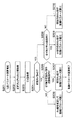
図2は、撮像装置100における制御パラメータ演算処理を示すフローチャートである。尚、本実施の形態では、制御パラメータ演算処理はライブビュー機能を開始する時、およびライブビュー中に所定期間が経過するごとに行われるものとする。
FIG. 2 is a flowchart illustrating control parameter calculation processing in the
図2において、撮像装置のシステム制御部50は、制御パラメータ演算処理を開始すると(ステップS201)、次の値を取得する。即ち、前回の演算処理で算出された絞り値PreAvと、今回の演算処理を行う直前の被写体の輝度Evをそれぞれ取得する(ステップS202、ステップS203)。尚、今回の演算処理がライブビュー開始時に行われる演算処理である場合、今回の演算処理以前に演算処理が行われていないものとして、絞り値PreAv=0とする。
In FIG. 2, the
次に、システム制御部50は、今回の演算処理がライブビュー開始時に行われる演算処理であるかどうかを判定する(ステップS204)。ライブビュー開始時に行われる演算処理でない場合、被写体の輝度Evが、絞り値PreAvの連動範囲内にあるかどうかを確認し、絞り値を絞り値PreAvから変更する必要があるか否かを判定する(ステップS205)。
Next, the
被写体の輝度Evが連動範囲外の場合は、システム制御部50は、被写体の輝度Evが連動範囲内となるように制御パラメータ演算を行い、制御パラメータ(Tv、Av、Sv)の値を算出する(ステップS206)。一方、被写体の輝度Evが連動範囲内の場合は、システム制御部50は、絞り値PreAvに基づき制御パラメータ演算を行い、その他の制御パラメータ(Tv、Sv)の値を算出する(ステップS207)。
When the subject brightness Ev is out of the interlocking range, the
また、今回の演算処理がライブビュー開始時の演算処理である場合、システム制御部50は絞り値の変化点となる輝度と被写体の輝度Evを比較し、被写体の輝度Evが絞り値の変化点となる輝度を基準とした所定範囲内である否かを判定する(ステップS208)。なお、ここでの絞り値の変化点となる輝度は、後述の図3に示す実線の折り返し点の輝度とする。
Further, when the current calculation process is a calculation process at the start of live view, the
被写体の輝度Evが所定範囲内である場合は、システム制御部50は、絞り値Avの値がプログラム線図上で設定可能な最も小絞り側の絞り値となるように制御パラメータ演算を行い、制御パラメータ(Tv、Av、Sv)の値を算出する(ステップS209)。尚、プログラム線図上で設定可能な最も小絞り側の絞り値は、プログラム線図上で設定可能な最も大きい値が対応している。
When the luminance Ev of the subject is within the predetermined range, the
被写体の輝度Evが所定範囲外である場合は、システム制御部50は、プログラム線図上で設定可能な最も開放側の絞り値となるように制御パラメータ演算を行い、制御パラメータ(Tv、Av、Sv)の値を算出する(ステップS210)。尚、プログラム線図上で設定可能な最も開放側の絞り値は、プログラム線図上で設定可能な最も小さい値が対応している。
When the luminance Ev of the subject is out of the predetermined range, the
次に、撮像装置100の上記制御の具体例について図3乃至図5のプログラム線図を参照しながら説明する。
Next, a specific example of the control of the
図3は、撮像装置100で使用される通常のプログラム線図である。図4は、撮像装置100でライブビュー開始時に使用されるプログラム線図である。図5は、撮像装置100で蓄積時間Tvを高速側まで選択可能な場合に使用されるプログラム線図である。
FIG. 3 is a normal program diagram used in the
図3において、上側の横軸および左側の縦軸は被写体の輝度Ev、下側の横軸は撮像素子14に対する電荷の蓄積時間Tv、右側の縦軸は絞り値Avを示す。図3のプログラム線図を使用する撮像装置では、ISO感度:Svは100固定で、蓄積時間Tvは1/8〜1/8000、絞り値AvはF1.8〜F29の間で切り換えることで、被写体の輝度Ev0〜18の範囲内で適正な露出制御を行うことができる。本実施の形態では、被写体の輝度Evが図3の斜線で示す範囲にある場合、絞り値を被写体の輝度Evが変化しても変化しにくい絞り値に変更する点を特徴としている。
In FIG. 3, the upper horizontal axis and the left vertical axis indicate the luminance Ev of the subject, the lower horizontal axis indicates the charge accumulation time Tv with respect to the
被写体の輝度Evと比較するための絞り値の変化点となる輝度(所定輝度)は、図3の太い実線の折り返し点(左上向きの矢印に対応する角の変化点)、太い2点鎖線の折り返し点(右下向きの矢印に対応する角の変化点)に相当する。すなわち、絞り値を大きくする変化点となる輝度が太い実線の折り返し点に相当し、絞り値を小さくする変化点となる輝度が太い2点鎖線の折り返し点に相当する。上述した図2のステップS208では、絞り値を大きくする変化点となる輝度が太い実線の折り返し点を絞り値の変化点となる輝度としている。 The brightness (predetermined brightness) as a change point of the aperture value for comparison with the brightness Ev of the subject is indicated by the bold solid line turning point (the change point of the corner corresponding to the upper left arrow) in FIG. It corresponds to the turning point (the change point of the corner corresponding to the arrow pointing downward to the right). That is, the luminance that becomes a change point for increasing the aperture value corresponds to a turning point of a thick solid line, and the luminance that serves as a changing point for decreasing the aperture value corresponds to a turning point of a two-dot chain line. In step S208 of FIG. 2 described above, the turning point of a solid line with a thick luminance that becomes a changing point for increasing the aperture value is set as the luminance that becomes the changing point of the aperture value.
図3に示すように、プログラム線図としては、絞り値をできるだけ一定に維持するように制御するAv優先で、F1.8で輝度Ev0〜8が連動範囲、F7.1で輝度Ev4〜12、F29で輝度Ev8〜18が連動範囲となっている。絞り値AvがF1.8からF7.1に変わるのは、絞り値AvがF1.8で制御されている時に、被写体の輝度がEv8を上回った時(図3の下側の実線の折り返し点)である。 As shown in FIG. 3, as a program diagram, with priority given to Av so as to maintain the aperture value as constant as possible, the luminance Ev0 to 8 is an interlocking range at F1.8, the luminance Ev4 to 12 at F7.1, In F29, the luminances Ev8 to 18 are in the interlocking range. The aperture value Av changes from F1.8 to F7.1 when the subject brightness exceeds Ev8 when the aperture value Av is controlled at F1.8 (the folding point of the lower solid line in FIG. 3). ).
また、絞り値AvがF7.1になった後、絞り値AvがF1.8になるのは、被写体の輝度がEv4を下回った時(図3の下側の2点鎖線の折り返し点)である。つまり、図3のプログラム線図では、絞りを絞る時の制御を実線で表し、絞りを開く時の制御を2点鎖線で表している。また、絞り値AvがF7.1からF29に変わる場合、絞り値AvがF29からF7.1に変わる場合も同様である。 Further, after the aperture value Av becomes F7.1, the aperture value Av becomes F1.8 when the brightness of the subject is lower than Ev4 (the folding point of the two-dot chain line on the lower side of FIG. 3). is there. That is, in the program diagram of FIG. 3, the control when the aperture is reduced is indicated by a solid line, and the control when the aperture is opened is indicated by a two-dot chain line. The same applies when the aperture value Av changes from F7.1 to F29 and when the aperture value Av changes from F29 to F7.1.
上記の図2のフローチャートと図3のプログラム線図から、撮像装置においてライブビュー中であれば、上述した通り、絞り値AvがF1.8からF7.1に変わるのは被写体の輝度Evが8を上回った場合である。 From the flowchart in FIG. 2 and the program diagram in FIG. 3, if the image capturing apparatus is in live view, the aperture value Av changes from F1.8 to F7.1 as described above. It is a case where it exceeds.
従来は、ライブビュー開始時は主被写体に比べ主被写体以外がよりぼける現象を緩和するため、および焦点合わせの精度がはっきり分かるようにするために、開放側の絞り値を選択するようにしていた。しかしながら、ライブビュー開始時の被写体の輝度が例えばEv7からEv8の範囲の場合、被写体の輝度が1Evでも明るくなると絞りが変わってしまい、表示画像の深度が変わったり、絞り駆動に伴う不快な音や表示画像の露出の乱れが発生したりする。 Conventionally, at the start of live view, the aperture value on the open side was selected to alleviate the phenomenon of blurring other than the main subject compared to the main subject, and to clearly see the focusing accuracy. . However, when the luminance of the subject at the start of live view is in the range of Ev7 to Ev8, for example, the aperture changes when the luminance of the subject becomes 1 Ev. Disturbed exposure of the displayed image may occur.
そこで、本実施の形態では、ライブビュー開始時の被写体の輝度が絞り値を大きくする変化点となる輝度を基準とした所定範囲内であれば、被写体の輝度の変化に対して絞り値がより変化しにくいように制御する。具体的には、ライブビュー開始時の被写体の輝度がEv7からEv8の範囲内、あるいはEv11からEv12の範囲内であれば小絞り側の絞り値を選択し、そうでなければ開放側の絞り値を選択するように制御する。そして、選択された絞り値および被写体の輝度に基づいてその他の制御パラメータの制御値を算出する。 Therefore, in the present embodiment, if the luminance of the subject at the start of live view is within a predetermined range based on the luminance that becomes the changing point for increasing the aperture value, the aperture value is more suitable for the change in the luminance of the subject. Control so that it does not change easily. Specifically, if the luminance of the subject at the start of live view is within the range of Ev7 to Ev8, or within the range of Ev11 to Ev12, the aperture value on the small aperture side is selected. Otherwise, the aperture value on the open side is selected. Control to select. Then, control values of other control parameters are calculated based on the selected aperture value and the luminance of the subject.
これに対し、表示画像のフレーム間の連続性が損なわれないように蓄積時間Tvが長くなるように制御するTV優先の場合は、次のように演算処理を行ってもよい。Av優先の場合とは異なり、ライブビュー開始時の被写体の輝度が絞り値を小さくする変化点となる輝度を基準とした所定範囲内であれば、開放側の絞り値を選択し、そうでなければ小絞り側の絞り値を選択するように制御すればよい。 On the other hand, in the case of TV priority in which the accumulation time Tv is controlled to be long so that the continuity between frames of the display image is not impaired, the arithmetic processing may be performed as follows. Unlike the case of Av priority, if the brightness of the subject at the start of the live view is within a predetermined range based on the brightness that becomes the changing point for reducing the aperture value, the aperture value on the open side must be selected. For example, control may be performed so that the aperture value on the small aperture side is selected.
すなわち、被写体の輝度が変化点となる輝度を上回ったら絞り値を大きくする場合、ライブビュー開始時の変化点となる輝度をライブビュー中の変化点の輝度よりも低輝度とする。一方、被写体の輝度が変化点となる輝度を下回ったら絞り値を小さくする場合、ライブビュー開始時の変化点となる輝度をライブビュー中の変化点の輝度よりも高輝度とする。 また、本実施の形態では、説明の便宜上、ライブビュー開始時に絞り値の選択を切り換える段数を1段としたが、これに限定されるものではない。変化点となる輝度を基準とした所定範囲は、本発明の主旨を逸脱しない範囲で変更してもよい。 That is, when the aperture value is increased when the luminance of the subject exceeds the luminance at the change point, the luminance at the change point at the start of the live view is set to be lower than the luminance at the change point in the live view. On the other hand, when the aperture value is decreased when the luminance of the subject falls below the change point luminance, the luminance that is the change point at the start of the live view is set to be higher than the luminance of the change point during the live view. Further, in the present embodiment, for convenience of explanation, the number of stages for switching the selection of the aperture value at the start of the live view is one, but the present invention is not limited to this. The predetermined range based on the luminance serving as the change point may be changed without departing from the gist of the present invention.
また、本実施の形態では、1つのプログラム線図を用いて、ライブビュー開始時の輝度とプログラム線図の絞り値の変化点となる輝度との差を比較した結果に基づき絞り値を切り換えるが、これに限定されるものではない。撮像装置のシステム制御部50が、図4に示すような、ライブビュー開始時用のプログラム線図を別に装備してもよい。例えば、図2のステップS204においてライブビュー開始時に行われる演算処理であると判定された場合に、プログラム線図を図4に示すプログラム線図に切り換えてそれぞれの制御パラメータの値を算出するようにすればよい。
In the present embodiment, the aperture value is switched based on the result of comparing the difference between the luminance at the start of the live view and the luminance that is the change point of the aperture value in the program diagram using one program diagram. However, the present invention is not limited to this. The
尚、ライブビュー中に表示する撮影前画像のフレーム間の連続性が損なわれるか否かは、ライブビュー中の撮像素子14への電荷の蓄積時間と撮像画面における被写体の動きとに密接に関わってくる。例えば、動きが遅い被写体もしくは動いていない被写体に対しては、蓄積時間を短くしても、フレーム間の連続性が損なわれる可能性は低い。
Note that whether or not the continuity between frames of the pre-photographing image displayed during live view is lost is closely related to the charge accumulation time in the
そこで、被写体の動きが所定量以下であれば、図5に示す蓄積時間Tvを高速側まで使用可能なプログラム線図を用いてもよい。図5のプログラム線図では、蓄積時間Tvをより高速側まで使用することができ、その分、絞り値をより一定に維持するように制御することができる。 Therefore, if the movement of the subject is not more than a predetermined amount, a program diagram that can use the accumulation time Tv shown in FIG. 5 up to the high speed side may be used. In the program diagram of FIG. 5, the accumulation time Tv can be used up to a higher speed side, and the aperture value can be controlled to be kept constant accordingly.
尚、被写体の動きが所定量以下か否かの判定は画像処理回路20で行えばよく、被写体の動き(動き量)或いは被写体が移動する速度を検出する方法としては、以下の方法のいずれを用いてもよい。即ち、連続するフレーム間の相関に基づいて被写体の動き或いは速度を検出する方法、撮像素子14により撮像した画像のコントラスト成分の変化(撮像面AFの評価値の変化量)に基づいて被写体の動き或いは速度を検出する方法のいずれを用いてもよい。
Note that the
ただし、上述したいずれの方法を用いて被写体の動きが所定量以下か否かの判定を行う場合でも、ライブビュー開始時には画像が取得されていないので判定することができない。そのため、図2におけるステップS204で今回の演算処理がライブビュー開始時に行われる演算処理ではないと判定された場合に、ステップS205を行う前に被写体の動きが所定量以下か否かを判定すればよい。 However, even when using any of the methods described above to determine whether or not the movement of the subject is equal to or less than a predetermined amount, the determination cannot be made because no image has been acquired at the start of live view. Therefore, if it is determined in step S204 in FIG. 2 that the current calculation process is not the calculation process performed at the start of the live view, it is determined whether or not the movement of the subject is equal to or less than a predetermined amount before performing step S205. Good.
以上詳細に説明したように、本実施の形態では、ライブビュー開始時における絞り値をプログラム線図に基づき決定する際に、被写体の輝度の変化があっても絞り値の変化を抑えるように制御している。これにより、絞り変化による深度の変化、音の変化、画面の輝度変化などが生じる頻度を低減することが可能となるため、操作者が感じる違和感を生じにくくすることが可能となる。 As described above in detail, in this embodiment, when the aperture value at the start of live view is determined based on the program diagram, control is performed so as to suppress the change in aperture value even if there is a change in the luminance of the subject. doing. As a result, it is possible to reduce the frequency with which changes in depth, changes in sound, changes in screen brightness, and the like occur due to a change in aperture, so that it is possible to make it difficult for the operator to feel discomfort.
〔他の実施の形態〕
また、本発明の目的は、以下の処理を実行することにより達成される。即ち、上述した実施形態の機能を実現するソフトウェアのプログラムコードを記録した記憶媒体を、システム或いは装置に供給し、そのシステム或いは装置のコンピュータ(又はCPUやMPU等)が記憶媒体に格納されたプログラムコードを読み出す処理である。
[Other Embodiments]
The object of the present invention is achieved by executing the following processing. That is, a storage medium that records a program code of software that realizes the functions of the above-described embodiments is supplied to a system or apparatus, and a computer (or CPU, MPU, etc.) of the system or apparatus is stored in the storage medium. This is the process of reading the code.
この場合、記憶媒体から読み出されたプログラムコード自体が前述した実施の形態の機能を実現することになり、そのプログラムコード及び該プログラムコードを記憶した記憶媒体は本発明を構成することになる。 In this case, the program code itself read from the storage medium realizes the functions of the above-described embodiments, and the program code and the storage medium storing the program code constitute the present invention.
また、プログラムコードを供給するための記憶媒体としては、次のものを用いることができる。例えば、フロッピー(登録商標)ディスク、ハードディスク、光磁気ディスク、CD−ROM、CD−R、CD−RW、DVD−ROM、DVD−RAM、DVD−RW、DVD+RW、磁気テープ、不揮発性のメモリカード、ROM等である。または、プログラムコードをネットワークを介してダウンロードしてもよい。 Moreover, the following can be used as a storage medium for supplying the program code. For example, floppy (registered trademark) disk, hard disk, magneto-optical disk, CD-ROM, CD-R, CD-RW, DVD-ROM, DVD-RAM, DVD-RW, DVD + RW, magnetic tape, nonvolatile memory card, ROM or the like. Alternatively, the program code may be downloaded via a network.
また、コンピュータが読み出したプログラムコードを実行することにより、上記実施の形態の機能が実現される場合も本発明に含まれる。加えて、そのプログラムコードの指示に基づき、コンピュータ上で稼動しているOS(オペレーティングシステム)等が実際の処理の一部または全部を行い、その処理により前述した実施形態の機能が実現される場合も含まれる。 Further, the present invention includes a case where the function of the above-described embodiment is realized by executing the program code read by the computer. In addition, an OS (operating system) running on the computer performs part or all of the actual processing based on an instruction of the program code, and the functions of the above-described embodiments are realized by the processing. Is also included.
更に、前述した実施形態の機能が以下の処理により実現される場合も本発明に含まれる。即ち、記憶媒体から読み出されたプログラムコードが、コンピュータに挿入された機能拡張ボードやコンピュータに接続された機能拡張ユニットに備わるメモリに書き込まれる。その後、そのプログラムコードの指示に基づき、その機能拡張ボードや機能拡張ユニットに備わるCPU等が実際の処理の一部または全部を行う場合である。 Furthermore, the present invention includes a case where the functions of the above-described embodiment are realized by the following processing. That is, the program code read from the storage medium is written in a memory provided in a function expansion board inserted into the computer or a function expansion unit connected to the computer. Thereafter, based on the instruction of the program code, the CPU or the like provided in the function expansion board or function expansion unit performs part or all of the actual processing.
14 撮像素子
20 画像処理回路
29 画像表示部
50 システム制御部
100 撮像装置
300 レンズユニット
312 絞り
14
Claims (10)
前記撮像素子を用いて得られた画像を逐次表示することが可能な表示手段と、を備え、絞りを制御して前記撮像素子へ入射する光量を調整する撮像装置であって、
前記被写体の輝度を算出する算出手段と、
前記算出手段により算出された輝度が所定範囲にある場合に前記絞りの絞り値を変更する制御手段と、を有し、
前記制御手段は、前記表示手段による前記画像の逐次表示の開始前と逐次表示中とで前記所定範囲を変更し、前記画像の逐次表示の開始前に前記被写体の輝度が前記所定範囲にある場合は前記画像の逐次表示の開始前に前記絞り値を変更することを特徴とする撮像装置。 An image sensor that converts an optical image of a subject into an electrical signal;
An image pickup apparatus that adjusts an amount of light incident on the image pickup device by controlling a diaphragm, and a display unit capable of sequentially displaying images obtained using the image pickup device.
Calculating means for calculating the luminance of the subject;
Control means for changing the aperture value of the aperture when the brightness calculated by the calculating device is within a predetermined range;
The control unit changes the predetermined range before and after the sequential display of the image by the display unit, and the luminance of the subject is within the predetermined range before the sequential display of the image is started. The imaging apparatus is characterized in that the aperture value is changed before the start of sequential display of the images.
前記表示手段による前記画像の逐次表示中における前記第1の範囲の最低輝度を第2の輝度、
前記被写体の輝度が前記第1の範囲にある場合に大きくした前記絞り値を小さくする輝度であり、前記第1の範囲外にある第3の輝度、とした場合、
前記第1の輝度と前記第2の輝度との差が、前記第1の輝度と前記第3の輝度との差より小さいことを特徴とする請求項3に記載の撮像装置。 Sequentially displaying the first range minimum luminance of the first luminance before the start of the image by the display means,
The lowest luminance in the first range during the sequential display of the image by the display means is a second luminance,
When the brightness of the subject is within the first range, the brightness is reduced to reduce the aperture value, and the third brightness is outside the first range.
The imaging apparatus according to claim 3, wherein a difference between the first luminance and the second luminance is smaller than a difference between the first luminance and the third luminance.
前記表示手段による前記画像の逐次表示中における前記第1の範囲の最高輝度を第2の輝度、
前記被写体の輝度が前記第1の範囲にある場合に小さくした前記絞り値を大きくする輝度であり、前記第1の範囲外にある第3の輝度、とした場合、
前記第1の輝度と前記第2の輝度との差が、前記第1の輝度と前記第3の輝度との差より小さいことを特徴とする請求項5に記載の撮像装置。 Maximum brightness the first luminance sequential display the first range before the start of the image by the display means,
The highest luminance in the first range during the sequential display of the image by the display means is the second luminance,
When the luminance of the subject is in the first range, the luminance is increased to reduce the aperture value, and the third luminance is outside the first range,
The imaging apparatus according to claim 5, wherein a difference between the first luminance and the second luminance is smaller than a difference between the first luminance and the third luminance.
前記制御手段は、前記動き検出手段により検出された前記被写体の動きに応じて前記所定範囲を変更することを特徴とする請求項1ないし請求項6のいずれか1項に記載の撮像装置。 A motion detection means for detecting the motion of the subject on the imaging screen;
The imaging apparatus according to claim 1, wherein the control unit changes the predetermined range in accordance with a movement of the subject detected by the movement detection unit.
前記被写体の輝度を算出する算出工程と、
前記算出工程により算出された輝度が所定範囲にある場合に前記絞りの絞り値を変更する制御工程と、を有し、
前記制御工程は、前記表示手段による前記画像の逐次表示の開始前と逐次表示中とで前記所定範囲を変更し、前記画像の逐次表示の開始前に前記被写体の輝度が前記所定範囲にある場合は前記画像の逐次表示の開始前に前記絞り値を変更することを特徴とする撮像装置の制御方法。 An image sensor that converts an optical image of a subject into an electrical signal; and display means that can sequentially display an image obtained by using the image sensor, and controls the aperture to enter the image sensor A control method for an imaging apparatus that adjusts the amount of light,
A calculation step of calculating the luminance of the subject;
A control step of changing the aperture value of the aperture when the luminance calculated by the calculation step is within a predetermined range,
The control step changes the predetermined range before and after the sequential display of the images by the display unit, and the luminance of the subject is within the predetermined range before the sequential display of the images is started. A method for controlling an imaging apparatus, wherein the aperture value is changed before the start of sequential display of the images.
Priority Applications (1)
| Application Number | Priority Date | Filing Date | Title |
|---|---|---|---|
| JP2009032868A JP5371474B2 (en) | 2009-02-16 | 2009-02-16 | Imaging apparatus, control method, and program |
Applications Claiming Priority (1)
| Application Number | Priority Date | Filing Date | Title |
|---|---|---|---|
| JP2009032868A JP5371474B2 (en) | 2009-02-16 | 2009-02-16 | Imaging apparatus, control method, and program |
Publications (3)
| Publication Number | Publication Date |
|---|---|
| JP2010192991A JP2010192991A (en) | 2010-09-02 |
| JP2010192991A5 JP2010192991A5 (en) | 2012-03-29 |
| JP5371474B2 true JP5371474B2 (en) | 2013-12-18 |
Family
ID=42818598
Family Applications (1)
| Application Number | Title | Priority Date | Filing Date |
|---|---|---|---|
| JP2009032868A Active JP5371474B2 (en) | 2009-02-16 | 2009-02-16 | Imaging apparatus, control method, and program |
Country Status (1)
| Country | Link |
|---|---|
| JP (1) | JP5371474B2 (en) |
Families Citing this family (4)
| Publication number | Priority date | Publication date | Assignee | Title |
|---|---|---|---|---|
| JP5929712B2 (en) | 2012-11-06 | 2016-06-08 | セイコーエプソン株式会社 | Image capturing apparatus and image capturing apparatus control method |
| JP6028928B2 (en) * | 2013-04-16 | 2016-11-24 | オリンパス株式会社 | Imaging apparatus and imaging method |
| US10142086B2 (en) | 2015-06-11 | 2018-11-27 | At&T Intellectual Property I, L.P. | Repeater and methods for use therewith |
| WO2020017597A1 (en) | 2018-07-18 | 2020-01-23 | 株式会社ニコン | Image capturing device |
Family Cites Families (2)
| Publication number | Priority date | Publication date | Assignee | Title |
|---|---|---|---|---|
| JP2004056699A (en) * | 2002-07-24 | 2004-02-19 | Kyocera Corp | Camera with moving picture photographing function |
| JP4761048B2 (en) * | 2006-01-11 | 2011-08-31 | カシオ計算機株式会社 | Imaging apparatus and program thereof |
-
2009
- 2009-02-16 JP JP2009032868A patent/JP5371474B2/en active Active
Also Published As
| Publication number | Publication date |
|---|---|
| JP2010192991A (en) | 2010-09-02 |
Similar Documents
| Publication | Publication Date | Title |
|---|---|---|
| US7657164B2 (en) | Subject shake detection device, imaging device, control method thereof, control program, and recording medium | |
| JP5115210B2 (en) | Imaging device | |
| JP2007019973A (en) | Imaging device and imaging method | |
| KR20070080223A (en) | Image pickup device and image blurring method and recording medium thereof | |
| US10116876B2 (en) | Image capturing method and apparatus, with reduced saturation and improved signal-to-noise ratio based on a dynamic range | |
| JP5967865B2 (en) | IMAGING DEVICE, IMAGING DEVICE CONTROL METHOD, AND PROGRAM | |
| JP4614143B2 (en) | Imaging apparatus and program thereof | |
| US20170318208A1 (en) | Imaging device, imaging method, and image display device | |
| JP2007178576A (en) | Imaging apparatus and program therefor | |
| JP5371474B2 (en) | Imaging apparatus, control method, and program | |
| JP5217451B2 (en) | Imaging device | |
| KR20090095920A (en) | Apparatus for Photographing Digital Images, Method of Controlling Exposure, Method of Photographing Digital Images, and Computer Readable Recording Medium Storing Program for the Same Method of Photographing | |
| CN109964479B (en) | Image pickup apparatus and control method thereof | |
| US11190704B2 (en) | Imaging apparatus and control method for performing live view display of a tracked object | |
| JP6652303B2 (en) | Flash band determination device, control method thereof, control program, and imaging device | |
| US9992426B2 (en) | Image capturing apparatus, method for controlling the same, and storage medium | |
| JP5169542B2 (en) | Electronic camera | |
| JP6335497B2 (en) | Imaging device, control method thereof, and control program | |
| JP6294607B2 (en) | IMAGING DEVICE, ITS CONTROL METHOD, PROGRAM, AND STORAGE MEDIUM | |
| JP2022170553A (en) | Imaging apparatus, method for controlling the same, and program | |
| JP2007057974A (en) | Photographing device | |
| JP2015167308A (en) | Photometry method suitable for face detection autofocus control | |
| JP2008219334A (en) | Electronic camera | |
| JP2009118247A (en) | Photographic device | |
| JP2008193635A (en) | Electronic camera |
Legal Events
| Date | Code | Title | Description |
|---|---|---|---|
| A521 | Request for written amendment filed |
Free format text: JAPANESE INTERMEDIATE CODE: A523 Effective date: 20120209 |
|
| A621 | Written request for application examination |
Free format text: JAPANESE INTERMEDIATE CODE: A621 Effective date: 20120209 |
|
| A977 | Report on retrieval |
Free format text: JAPANESE INTERMEDIATE CODE: A971007 Effective date: 20121213 |
|
| A131 | Notification of reasons for refusal |
Free format text: JAPANESE INTERMEDIATE CODE: A131 Effective date: 20130115 |
|
| A521 | Request for written amendment filed |
Free format text: JAPANESE INTERMEDIATE CODE: A523 Effective date: 20130219 |
|
| A131 | Notification of reasons for refusal |
Free format text: JAPANESE INTERMEDIATE CODE: A131 Effective date: 20130416 |
|
| A521 | Request for written amendment filed |
Free format text: JAPANESE INTERMEDIATE CODE: A523 Effective date: 20130603 |
|
| TRDD | Decision of grant or rejection written | ||
| A01 | Written decision to grant a patent or to grant a registration (utility model) |
Free format text: JAPANESE INTERMEDIATE CODE: A01 Effective date: 20130820 |
|
| A61 | First payment of annual fees (during grant procedure) |
Free format text: JAPANESE INTERMEDIATE CODE: A61 Effective date: 20130917 |
|
| R151 | Written notification of patent or utility model registration |
Ref document number: 5371474 Country of ref document: JP Free format text: JAPANESE INTERMEDIATE CODE: R151 |