JP4615563B2 - Sculpture photography using optical tiles - Google Patents
Sculpture photography using optical tiles Download PDFInfo
- Publication number
- JP4615563B2 JP4615563B2 JP2007516925A JP2007516925A JP4615563B2 JP 4615563 B2 JP4615563 B2 JP 4615563B2 JP 2007516925 A JP2007516925 A JP 2007516925A JP 2007516925 A JP2007516925 A JP 2007516925A JP 4615563 B2 JP4615563 B2 JP 4615563B2
- Authority
- JP
- Japan
- Prior art keywords
- tile
- orientation angle
- substrate
- tile element
- image
- Prior art date
- Legal status (The legal status is an assumption and is not a legal conclusion. Google has not performed a legal analysis and makes no representation as to the accuracy of the status listed.)
- Expired - Fee Related
Links
Images


Classifications
-
- G—PHYSICS
- G02—OPTICS
- G02B—OPTICAL ELEMENTS, SYSTEMS OR APPARATUS
- G02B26/00—Optical devices or arrangements for the control of light using movable or deformable optical elements
- G02B26/02—Optical devices or arrangements for the control of light using movable or deformable optical elements for controlling the intensity of light
-
- G—PHYSICS
- G09—EDUCATION; CRYPTOGRAPHY; DISPLAY; ADVERTISING; SEALS
- G09F—DISPLAYING; ADVERTISING; SIGNS; LABELS OR NAME-PLATES; SEALS
- G09F19/00—Advertising or display means not otherwise provided for
- G09F19/12—Advertising or display means not otherwise provided for using special optical effects
- G09F19/14—Advertising or display means not otherwise provided for using special optical effects displaying different signs depending upon the view-point of the observer
-
- B—PERFORMING OPERATIONS; TRANSPORTING
- B44—DECORATIVE ARTS
- B44F—SPECIAL DESIGNS OR PICTURES
- B44F1/00—Designs or pictures characterised by special or unusual light effects
- B44F1/02—Designs or pictures characterised by special or unusual light effects produced by reflected light, e.g. matt surfaces, lustrous surfaces
-
- B—PERFORMING OPERATIONS; TRANSPORTING
- B44—DECORATIVE ARTS
- B44F—SPECIAL DESIGNS OR PICTURES
- B44F7/00—Designs imitating three-dimensional effects
-
- G—PHYSICS
- G09—EDUCATION; CRYPTOGRAPHY; DISPLAY; ADVERTISING; SEALS
- G09F—DISPLAYING; ADVERTISING; SIGNS; LABELS OR NAME-PLATES; SEALS
- G09F9/00—Indicating arrangements for variable information in which the information is built-up on a support by selection or combination of individual elements
- G09F9/30—Indicating arrangements for variable information in which the information is built-up on a support by selection or combination of individual elements in which the desired character or characters are formed by combining individual elements
- G09F9/37—Indicating arrangements for variable information in which the information is built-up on a support by selection or combination of individual elements in which the desired character or characters are formed by combining individual elements being movable elements
- G09F9/375—Indicating arrangements for variable information in which the information is built-up on a support by selection or combination of individual elements in which the desired character or characters are formed by combining individual elements being movable elements the position of the elements being controlled by the application of a magnetic field
-
- G—PHYSICS
- G16—INFORMATION AND COMMUNICATION TECHNOLOGY [ICT] SPECIALLY ADAPTED FOR SPECIFIC APPLICATION FIELDS
- G16B—BIOINFORMATICS, i.e. INFORMATION AND COMMUNICATION TECHNOLOGY [ICT] SPECIALLY ADAPTED FOR GENETIC OR PROTEIN-RELATED DATA PROCESSING IN COMPUTATIONAL MOLECULAR BIOLOGY
- G16B10/00—ICT specially adapted for evolutionary bioinformatics, e.g. phylogenetic tree construction or analysis
-
- Y—GENERAL TAGGING OF NEW TECHNOLOGICAL DEVELOPMENTS; GENERAL TAGGING OF CROSS-SECTIONAL TECHNOLOGIES SPANNING OVER SEVERAL SECTIONS OF THE IPC; TECHNICAL SUBJECTS COVERED BY FORMER USPC CROSS-REFERENCE ART COLLECTIONS [XRACs] AND DIGESTS
- Y10—TECHNICAL SUBJECTS COVERED BY FORMER USPC
- Y10T—TECHNICAL SUBJECTS COVERED BY FORMER US CLASSIFICATION
- Y10T29/00—Metal working
- Y10T29/49—Method of mechanical manufacture
Abstract
Description
本発明は画像を表示する構造に関し、特に光を反射する、または屈折させる複数のタイル要素を含む構造に関する。 The present invention relates to a structure for displaying an image, and more particularly to a structure including a plurality of tile elements that reflect or refract light.
画像は多くの場合、塗料またはインクを2次元表面に吐出することにより表示される。このような画像を含む表示は容易に生成することができるが、視覚的に動的ではない。
芸術家のダニエルローズィン(Daniel Rozin)は、http://fargo.itp.tsoa.nyu.edu/〜danny/mirror.htmlにて説明されている「Wooden Mirror」として知られる、画像を表示する装置を開発している。Wooden Mirrorは複数の木片を含み、これらの木片の各々はサーボモータに接続され、かつ約30度の角度だけ上下に傾けることができる。Wooden Mirrorを上から照らすと、上に傾いた木片が明るく見え、そして下に傾いた木片が暗く見える。
Images are often displayed by ejecting paint or ink onto a two-dimensional surface. A display containing such an image can be easily generated, but is not visually dynamic.
The artist Daniel Rozin can be found at http: // fargo. itp. tsoa. nyu. edu / ~ danny / mirror. A device for displaying images, known as “Wooden Mirror” described in html, is being developed. The Wooden Mirror includes a plurality of pieces of wood, each of which is connected to a servo motor and can be tilted up and down by an angle of about 30 degrees. When the Wood Mirror is illuminated from above, the wood pieces tilted up look bright and the wood pieces leaning down look dark.
テキサスインスツルメンツ社(Texas Instrument(商標) Incorporated)は、デジタルマイクロミラーデバイス(digital micro−mirror devices:DMD)を用いるデジタルライトプロセッシング(Digital Light Processing(商標))技術を開発した。ペン(Penn)らによる米国特許第6,857,751号明細書に開示されているように、DMDは、「数千の傾斜するミラーのアレイを含む微小電気機械デバイスである。各ミラーは、活性「オン」状態または「オフ」状態に対応して+10度または−10度だけ傾くことができる。これらのミラーが傾くことができるようにするために、各ミラーは支持ポストに装着された一つ以上のヒンジに取り付けられ、下方の制御回路の上のエアギャップによって分離される。」
関連技術における前述の例及びこれらの例の限界は例示であり、全てを網羅したものではない。当業者は、関連技術の他の限界を明細書の記載及び図の参酌により理解し得る。
Texas Instruments (TM) Incorporated has developed Digital Light Processing (TM) technology using digital micro-mirror devices (DMD). As disclosed in US Pat. No. 6,857,751 by Penn et al., DMD is “a microelectromechanical device that includes an array of thousands of tilting mirrors. It can be tilted by +10 degrees or −10 degrees in response to an active “on” or “off” state. In order to allow these mirrors to tilt, each mirror is attached to one or more hinges mounted on a support post and separated by an air gap above the lower control circuit. "
The foregoing examples in the related art and the limitations of these examples are illustrative and not exhaustive. One skilled in the art can understand other limitations of the related art by referring to the description and the drawings.
以下に、複数の実施形態及びこれらの実施形態の態様をシステム、ツール、及び方法に関して記載及び説明する。なお、これらのシステム、ツール、及び方法は一例かつ例示である。種々の実施形態では、上述した従来技術の問題の一つ以上が軽減されているか、または解消されている。他の実施形態は他の改良を行なうために提示される。 In the following, embodiments and aspects of these embodiments are described and described with respect to systems, tools, and methods. Incidentally, these systems, tools, and methods Ru example and exemplification. In various embodiments, one or more of the problems of the prior art described above have been reduced or eliminated. Other embodiments are presented to make other improvements.
本発明の一つの態様は、複数の画素を有する画像を表示する構造を提供する。構造は、互いに固定された関係で保持される複数のタイル要素を備える。複数のタイル要素の各々は、基準平面に対して或る傾斜角で傾斜されたほぼ平坦な平坦面を含み、画像の少なくとも一つの画素に対応している。また、複数のタイル要素の各々は、基準方向に対する或る配向角を有する。配向角は、前記基準平面に対する前記平坦面の法線方向の投影像と前記基準平面に対する前記基準方向と平行な方向の投影像との間の角度として定義される。この配向角は、対応する前記少なくとも一つの画素の特性によって決定される。 One aspect of the present invention provides a structure for displaying an image having a plurality of pixels. The structure comprises a plurality of tile elements that are held in a fixed relationship with each other. Each of the plurality of tile elements includes a substantially flat flat surface inclined at a certain inclination angle with respect to the reference plane, and corresponds to at least one pixel of the image. Each of the plurality of tile elements has a certain orientation angle with respect to the reference direction. The orientation angle is defined as an angle between a projection image in a normal direction of the flat surface with respect to the reference plane and a projection image in a direction parallel to the reference direction with respect to the reference plane. This orientation angle is determined by the characteristics of the corresponding at least one pixel.
本発明の別の態様は、複数の画素を有する画像を表示する構造を提供する。構造は、互いに制御される関係で保持される複数のタイル要素を備える。複数のタイル要素の各々は、基準平面に対して或る傾斜角で傾斜されたほぼ平坦な平坦面を含み、画像の少なくとも一つの画素に対応している。また、複数のタイル要素の各々は、基準方向に対して或る配向角を有する。配向角は、前記基準平面に対する前記平坦面の法線方向の投影像と、前記基準平面に対する前記基準方向と平行な方向の投影像との間の角度として定義される。この配向角は、対応する前記少なくとも一つの画素の特性によって決定される。構造は更に、タイル要素群の配向角を制御システムによる制御下で動的に変化させる複数のアクチュエータを備える。各アクチュエータはタイル要素群の一つに接続されている。その結果、各タイル要素は、複数の異なる配向角のうちのいずれか一つの配向角を有するように移動する。 Another aspect of the present invention provides a structure for displaying an image having a plurality of pixels. The structure comprises a plurality of tile elements that are held in a controlled relationship with each other. Each of the plurality of tile elements includes a substantially flat flat surface inclined at a certain inclination angle with respect to the reference plane, and corresponds to at least one pixel of the image. Each of the plurality of tile elements has a certain orientation angle with respect to the reference direction. The orientation angle is defined as an angle between a projection image in the normal direction of the flat surface with respect to the reference plane and a projection image in a direction parallel to the reference direction with respect to the reference plane. This orientation angle is determined by the characteristics of the corresponding at least one pixel. The structure further comprises a plurality of actuators that dynamically change the orientation angle of the tile elements under control by the control system. Each actuator is connected to one of the tile elements. As a result, each tile element moves so as to have any one of a plurality of different orientation angles.
本発明の別の態様は、複数の画素を有する画像を表示する方法を含む。該方法は、互いに制御される関係で保持される複数のタイル要素を形成することを備える。複数のタイル要素の各々は、複数の画素の少なくとも一つの画素に対応し、かつほぼ平坦な平坦面を有する。方法は更に、光の入射方向を求めること、及び、各タイル要素を配向させることであって、平坦面が基準平面に対して或る傾斜角で傾斜するように、かつ基準平面に対する平坦面の法線方向の投影像と基準平面に対する光の入射方向の投影像とによって配向角が定義されるように、各タイル要素を配向させることを備える。各タイル要素の配向角は、対応する少なくとも一つの画素の特性によって決まる。 Another aspect of the present invention includes a method for displaying an image having a plurality of pixels. The method comprises forming a plurality of tile elements that are held in a controlled relationship with each other. Each of the plurality of tile elements has a substantially flat surface corresponding to at least one pixel of the plurality of pixels. The method further includes determining the direction of incidence of light and orienting each tile element so that the flat surface is inclined at a tilt angle with respect to the reference plane and the flat surface relative to the reference plane. Orienting each tile element such that an orientation angle is defined by a projected image in a normal direction and a projected image in a light incident direction with respect to a reference plane. The orientation angle of each tile element is determined by the characteristics of the corresponding at least one pixel.
上述の態様及び実施形態、更に別の態様及び実施形態は、図の参酌及び以下に示す詳細な説明の記載により理解し得る。 The aspects and embodiments described above, and further aspects and embodiments can be understood by referring to the drawings and the following detailed description.
例示としての実施形態は添付の図における参照用に示される。本明細書に記載する実施形態及び図は、本発明を制限するものとしてではなく、例示として捉えられるべきものである。これらの図には、本発明を制限することがない実施形態が示される。 Illustrative embodiments are shown for reference in the accompanying figures. The embodiments and figures described herein are to be taken as illustrative rather than limiting on the present invention. These figures illustrate embodiments that do not limit the invention.
本発明は画像を表示する構造を提供する。本発明による構造は複数のタイル要素を含み、複数のタイル要素は光源によって照明されると、各タイル要素は、光源に対する対応するタイル要素の配向角によって変わる或る量の光を、観察位置の観察者に振り向ける。各タイル要素の配向角は、画像の対応する画素の特性に基づいて選択される。その結果、観察者はタイル要素によって観察位置に振り向けられた光の量の変化により形成された画像の表示を見ることができる。 The present invention provides a structure for displaying an image. The structure according to the invention includes a plurality of tile elements, and when the plurality of tile elements are illuminated by a light source, each tile element emits a certain amount of light that varies depending on the orientation angle of the corresponding tile element relative to the light source. Turn to the observer. The orientation angle of each tile element is selected based on the characteristics of the corresponding pixel in the image. As a result, the observer can see the display of the image formed by the change in the amount of light directed to the viewing position by the tile element.
或る実施形態では、本発明は、構造の正面に入射する光を反射する構成の構造を提供する。構造は基板を備え、この基板は当該基板に接続された複数のタイル要素を有する。各タイル要素は反射タイルを含み、反射タイルは、基板に対して鋭角で傾斜するほぼ平坦な表面を有する。各タイル要素は、画像の複数の画素のうちの一つに対応する。複数のタイル要素は、構造に入射する光に対して配向される。その結果、画像の画素群のうち、最も明るさが明るい画素群に対応するタイル要素群が最大量の光を観察位置に向かって反射し、画像の画素群のうち、最も明るさが暗い画素群に対応するタイル要素群が最小量の光を観察位置に向かって反射するようになる。 In some embodiments, the present invention provides a structure configured to reflect light incident on the front of the structure. The structure comprises a substrate, the substrate having a plurality of tile elements connected to the substrate. Each tile element includes a reflective tile, the reflective tile having a substantially flat surface that is inclined at an acute angle to the substrate. Each tile element corresponds to one of a plurality of pixels of the image. The plurality of tile elements are oriented with respect to light incident on the structure. As a result, the tile element group corresponding to the brightest pixel group in the image pixel group reflects the maximum amount of light toward the observation position, and the darkest pixel in the image pixel group. The tile element group corresponding to the group reflects a minimum amount of light toward the observation position.
図1は本発明の一つの実施形態による構造10を示している。図2は図1のラインA−Aに沿った構造10の断面図である。構造10は3つの領域12,14,及び16を有する画像を表示し、矢印18で示す方向において構造10の正面に入射する光によって照明される。図1の例では矢印18は下を向き、これは、光が構造10に、該構造10のほぼ正面かつ上方の位置から入射することを意味する。
FIG. 1 illustrates a
構造10は基板20を備え、この基板は、当該基板に接続された複数のタイル要素22を有する。タイル要素群22は光を反射する材料により作製される。図1及び2の実施形態では、これらのタイル要素22は複数の円筒状突起24を含み、各突起は、基準平面に対して或る角度(「傾斜角」と呼ぶ)で傾いたせん断端面26を有する。図1及び2の実施形態では、基準平面は基板20の表面に平行であり、表面26は全てが約30度の傾斜角を有する。しかしながら、これらの表面26は異なる傾斜角を有することができ、かつ全ての表面26が同じ傾斜角を有する必要がある訳ではない。
The
各タイル要素22を配向させて、基準平面(すなわち、基板20の表面)に対する表面26の法線方向の投影像が、前記基準平面に対する基準方向(すなわち、光が構造10に入射する方向)に平行な方向の投影像と或る角度をなすようにする。この角度を本明細書では各タイル要素22の「配向角(orientation angle)」と呼ぶ。図29は、基準平面P及び入射光Lに対して表面S、傾斜角θ、及び配向角Φを有する一つのタイル要素の構成を示している。表面Sの法線の方向は参照記号Nにより示される。
With each
表面26は光を、タイル要素22の配向角によって変わる量だけ反射する。図1及び2の実施形態では、領域12の表面26は上を向き(すなわち、基準平面に対する表面26の法線方向の投影像、及び基準平面に対して光が構造10に入射する方向の投影像が平行であり、かつ同じ方向を指し、この状態は配向角がゼロである状態に対応する)、領域16の表面26は右を向き(すなわち、配向角が90度の状態)、そして領域16の表面は下を向く(すなわち、配向角が180度の状態)。従って、領域12のタイル要素22が最も明るく見える。その理由は、領域12に関連する表面26が最大量の光を反射するからである。領域14のタイル要素22が中程度に明るく見える。その理由は、領域14に関連する表面26が中程度の量の光を反射するからである。領域16のタイル要素が最も暗く見える。その理由は、領域16に関連する表面26が最も少ない量の光しか反射しないからである。
The
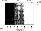
図3,4,及び5から分かるように、光が構造10に入射する方向を変えることにより構造10の見え方が変わる。図3では、光が構造10に構造10のほぼ正面、かつ下方の位置から入射し、領域12の明るさが最も暗く、そして領域16の明るさが最も明るい(すなわち、構造10は、図1に示す画像を反転した画像が表示される形で観察される)。その理由は、図3では、領域12の各タイル要素22の配向角が、光が構造10に入射する方向に対して180度であり、領域16の各タイル要素22の配向角が、光が構造10に入射する方向に対してゼロ度であるからである。
As can be seen from FIGS. 3, 4, and 5, changing the direction in which light is incident on the
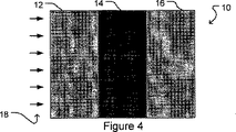
図4では、光が構造10に構造10のほぼ正面、かつ左の位置から入射し、領域12及び16の明るさが中程度の明るさとなり、領域14の明るさが最も暗い。その理由は、図4では、領域12及び16の各タイル要素22の配向角が、光が構造10に入射する方向に対して90度であり、領域14の各タイル要素22の配向角が、光が構造10に入射する方向に対して180度であるからである。
In FIG. 4, light is incident on the
図5では、光が構造10に構造10のほぼ正面、かつ右の位置から入射し、領域12及び16の明るさが中程度の明るさとなり、領域14の明るさが最も明るい(すなわち、構造10は図4に示す画像を反転した画像が表示される形で観察される)。その理由は、図5では、領域12及び16の各タイル要素22の配向角が、光が構造10に入射する方向に対して90度であり、領域14の各タイル要素22の配向角が、光が構造10に入射する方向に対してゼロ度であるからである。
In FIG. 5, light is incident on the
構造10を使用することによって、その構造10と同じ解像度(すなわち、画素の数が構造10のタイル要素22の数と同じ)を有する画像を、その画像の対応する画素の特性に基づいて各タイル要素22の傾斜角及び配向角を選択することにより表示することができる。例えば、各タイル要素22の傾斜角及び配向角は、対応する画素の輝度に基づいて選択することができる。また、構造10とは異なる解像度を有する画像は、その構造10と同じ解像度を有する対応する画像に公知の変換方法により変換することができる。別の構成として、各タイル要素22が画像の複数の画素に対応することができる、または複数のタイル要素22が画像の単一の画素に対応することができる。
By using the
上述したように、構造10のような構造により表示される画像は、異なる方向からの光によって照明されると異なって見える。また、このような画像は、異なる観察位置から眺めると異なって見える。その理由は、観察者の方に向いている各タイル要素22の表面積の割合は、観察者の位置によって変わるからである。構造10のような構造が基準平面と直交する方向から照明される場合でも、タイル要素22の表面積のうちの或る割合の面積が観察者の方に向いているので、観察者は所定の観察位置から、構造10によって表示される画像を眺めることができる。
As described above, an image displayed by a structure such as
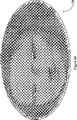
例えば、図6A〜6Cは本発明の別の実施形態による構造28を異なる観察角度から眺めたときの様子を示している。構造28はほぼ円形の基板を含み、この基板はタイル要素群を円筒状突起群の形で有し、これらの円筒状突起はモナリザ(Mona Lisa)の画像を表している。図6Aは鋭角の第1観察角度から眺めたときの構造28を示している。図6Bは鋭角の第2観察角度から眺めたときの構造28を示している。図6Cは垂直の観察角度から眺めたときの構造28を示している。観察者の方に向いているタイル要素群の表面積の割合が異なるので、観察角度が異なると、構造28によって表示される画像の輝度値が異なることが分かる。
For example, FIGS. 6A-6C illustrate a
別の例として、図1及び2によれば、領域14は、右から(すなわち、領域14の表面26が向いている方向から)眺めると相対的に明るく見え、左から(すなわち、領域14の表面26が向いている方向とは反対の方向から)眺めると相対的に暗く見える。従って、観察者が構造10のような構造の前を通り過ぎる場合、観察者には、観察者が移動するにつれて変化する輝度特性を有する画像が表示され、顕著な視覚効果が生じる。
As another example, according to FIGS. 1 and 2,
構造10のような構造は、構造に異なる角度で入射する、複数の異なる光源からの光で照明することができる。複数の異なる光源は異なるカラーの光を放出することができるので、観察者が眺めると、これらのカラーが混じって見える。
A structure such as
構造10のような構造によって生じる視覚効果は、コーティングを基板20及び/又は表面26に施すことにより強めることができる。例えば、平坦なコーティング、またはつや消しの白いコーティングを表面26に施し、黒いコーティングを基板20に施すことができる。別の構成として、表面26は虹色コーティングまたは蛍光コーティングで被覆することができる。また、反射率を強める、増やす、または変化させる他のコーティングを使用して基板20及び/又は表面26を被覆することもできるし、反射率を強める、増やす、または変化させる材料により基板20及び/又は表面26自体を構成することもできる。
The visual effect produced by structures such as
別の実施形態では、光をほとんど反射しないコーティングを基板20に施し、かつ光をほとんど反射するコーティングを表面26に施すこともできる。このような実施形態では、構造10は光源からの光を反射して画像をスクリーンなどに投影するように位置させることができる。構造10は別の構成として、または追加する形で、表面26が周囲環境のカラーを観察者に向けて反射するように位置させることもできる。
In another embodiment, a coating that reflects little light may be applied to the
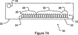
本発明の或る実施形態による構造は、半透明材料により構成することができ、かつ背面(すなわち、光が入射する側とは反対の側)から眺めることができる。図7及び7Aは画像Iを表示するために使用されるような構造30の例を示している。構造30は、光源34を収容するハウジング32に接続されている。構造30は、例えばガラスまたはアクリルのような半透明材料により構成されている。複数のタイル要素の間の基板20の領域は適宜、不透明コーティングを用いて不透明になるように作製したり、または被覆したりすることができる。或る実施形態では、1〜1.3の範囲の屈折率を有する半透明材料を使用することが望ましい。他の実施形態では、上記屈折率よりも大きい屈折率を有する半透明材料を選択することができる。
A structure according to an embodiment of the invention can be composed of a translucent material and can be viewed from the back (ie, the side opposite to the side on which light is incident). 7 and 7A show an example of a
光源34からの光は構造30のタイル要素群22の表面26に入射し、構造30によって屈折して画像Iを表示する。各タイル要素22は画像Iの少なくとも一つの画素に対応する。各タイル要素22の配向角は、光が表面26に、画像Iの対応する画素の特性(例えば、明度)によって変わる入射角で入射するように選択される。例えば、画像Iの明るさが最も明るい画素群に対応するタイル要素群22はゼロ度の配向角を有し(すなわち、表面26が光源34の方を向く)、図7Aでは一括して参照番号36で示される。また、タイル要素群22の傾斜角は、光源34から遠い表面26が光源34に近い表面26よりも大きい傾斜角を有するように、光源34からの距離によって変化させ、光源34からの光の入射角が、配向角がゼロ度の全てのタイル要素に関して相対的に一定になるようにすることができる。画像Iの明るさが最も暗い画素群に対応するタイル要素群22は180度の配向角(すなわち、表面26が光源34とは反対側の方向を向いている)、図7Aでは一括して参照番号38で示される。
Light from
構造30のような構造は、構造に異なる角度で入射する、複数の異なる光源からの光で照明することができる。複数の異なる光源は異なるカラーの光を放出して、観察者が眺める時にこれらのカラーが混ざって見えるようにすることができる。
Structures such as
構造10または構造30は、例えばブロック材料を加工して円筒状突起群24及び基板20を形成することにより構成することができる。次に、タイル要素群22は、円筒状突起群24を、表示される画像の画素群の特性に基づいてタイル要素群22に割り当てられる傾斜角及び配向角に従って切断することにより形成することができる。別の構成として、構造10または構造30は、予め形成されているタイル要素群22を基板に接着させることにより構成することができる。別の例では、構造10または構造30は、鋳型を作製し、成形材料をこの鋳型に流し込んで、成形材料を構造10または構造30の形状に硬化させることにより形成することができる。
The
図8は、例えば構造10または構造30のような構造を成形により形成するための装置40を示している。装置40は基台42と、基台から上方に延びて容積46を区画する壁44と、を備える。基台42には複数の凹部48が設けられる。成形材料を容積46の空間に流し込み、そして硬化させて表面を形成する。これにより、タイル要素群22が凹部群48に対応する突起群24を含むようになる。成形材料は、例えば容積に充填するか、容積の形にプレス加工するか、または容積の空間を減圧することにより容積の空間に吸引することができる。
FIG. 8 shows an
図9は、図8の凹部群48のうちの一つを示している。凹部48には円筒状プラグ50が収容される。円筒状プラグ50を矢印52で示す方向に回転させて、凹部48に形成されるタイル要素22の配向角を選択することができる。円筒状プラグ50の向きは制御システム54によって制御することができる。制御システム54を使用して、図8の凹部群48の全ての円筒状プラグ50の向きを制御することができる。
FIG. 9 shows one of the
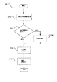
図10は、制御システム54によって実行される方法200を示すフローチャートである。ブロック202では、制御システム54は、装置40によって形成される構造により表示される画像を受信するとともに、当該形成される構造に入射される光の入射方向に関する情報を受信する。ブロック204では、制御システム54は、ブロック202で受信された画像の解像度を調整する必要があるかどうかについて(すなわち、画像が凹部48の数とは異なる数の画素を有するかどうかについて)判断する。解像度を調整する必要がある場合(ブロック204のYES出力)、方法200はブロック206に進み、このブロック206で、制御システム54は画像の解像度を調整して装置40の解像度に一致させる。画像が装置40よりも高い解像度を有する場合、画像の複数の画素をまとめてグループ化し、その複数の画素により単一の調整画素を計算により求め、1つの調整画素を各凹部48に対応させることにより、画像の解像度が調整される。画像が装置40よりも低い解像度を有する場合、画像の各画素を複数の調整画素に変換して、1つの調整画素を各凹部48に対応させることにより、画像の解像度が調整される。
FIG. 10 is a flowchart illustrating a
画像の解像度を調整する必要がない場合(ブロック204のNO出力)、または画像の解像度をブロック206で調整した後、方法200はブロック208に進む。このブロック208で、制御システム54は、画像の対応する画素群(または調整画素群)の特性に基づいて、凹部群48に形成されることになるタイル要素群に配向角を割り当てる。ブロック210では、制御システム54は円筒状プラグ50を、ブロック208において割り当てられた配向角に対応する向きになるように回転させ、装置40は成形材料を容積46に充填する準備が整う。図8の装置40は、例えば熱可塑性樹脂エンボス加工(thermo−plastic embossing)、または熱可塑性樹脂成形加工(thermo−plastic molding)を使用することにより、成形材料を容積46内に充填することができる。
If the image resolution does not need to be adjusted (NO output of block 204), or after adjusting the image resolution at
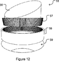
図11及び12は、本発明の別の実施形態によるタイル要素55を示している。タイル要素55はせん断円筒56を含み、このせん断円筒56は周辺鋸歯状の基台57を有する。周辺鋸歯状の基台57は環状部材58に収容され、この環状部材58は、対応する鋸歯形状の当該環状部材58の内側の周辺上に有する。環状部材58は基板の穴59に挿入される。鋸歯状基台57及び部材58の相互係合によって可能になる複数の向きのうちのいずれか一つの向きで、せん断円筒56の基台57を環状部材58に挿入して複数の離散値のうちのいずれか一つを選択することにより、タイル要素55の配向角を調整することができる。
11 and 12 illustrate a
図13は、本発明の別の実施形態による構造60を示している。構造60では、基板はシート62を備え、タイル要素群はタブ群64を含み、これらのタブ群はシート62により作製され、かつ所望の傾斜角及び配向角になるように曲げられる。また、図13の構造60はグラフィックパターン(図示せず)を含むことができる。例えば、タブ群64がシートによって作製される前か、または作製された後に、シート62を印刷するか、またはシートを非常に高い熱で処理することで、画像をシート上の顔料で形成することができる。
FIG. 13 shows a structure 60 according to another embodiment of the present invention. In structure 60, the substrate comprises a
本発明による構造は、タイル要素群が互いに対して高精度に制御された関係となるように保持される限り、基板を必ずしも備える必要はない。また、本発明の或る実施形態による構造は、互いに接続可能な複数の個々の基板要素を備えることができる。 The structure according to the invention does not necessarily need to comprise a substrate as long as the tile elements are held in a precisely controlled relationship with respect to each other. A structure according to an embodiment of the invention may also comprise a plurality of individual substrate elements that can be connected to each other.
図14は、個々の基板要素68により作製されるタブ64を含む1つのタイル要素66を示している。複数のタイル要素66は、これらの要素に対応する複数の基板要素68を接合させて図13の構造60のような構造を形成することにより組み合わせることができる。
FIG. 14 shows one
図15は、本発明の別の実施形態による構造70を示している。構造70では、基板は光媒質72を含み、タイル要素群は、媒質72内に懸濁させた複数の光透過防止領域(regions of interrupted transparency)74を含む。媒質72は、例えばガラスまたはアクリルのような透明材料を含むことができる。領域74は、例えば表面下におけるエッチングを媒質72中で行なうことにより形成することができる。別の方法として、領域74は、不透明部材または部分的に不透明な部材を媒質72に埋め込むことにより形成することができる。
FIG. 15 illustrates a
図16は、本発明の一つの実施形態による動画像を表示する動的構造80を示している。構造80は基板82を備え、この基板82は、基板82に接続された複数の能動タイル要素84を有する。能動タイル要素群84は制御システム86に動作可能に接続されるので、各能動タイル要素84の配向角を制御システム86によって動的に制御することができる。或る実施形態では、制御システム86は能動タイル要素群84の傾斜角を動的に制御することもできる。制御システム86は電力及び制御信号を構造80に供給する。図示の実施形態では、制御システム86は構造80にケーブルを通して接続され、制御システム86は別の構成として、構造80と無線手段により通信することができ、構造80は電力をソーラパネルから入力することもできる。
FIG. 16 illustrates a
図17は、本発明の一つの実施形態による例示としての能動タイル要素84Aを示している。能動タイル要素84Aは、回転アクチュエータ89に接続されたせん断円筒88を含む。回転アクチュエータ89は基板82(図17には示されず)に接続される。回転アクチュエータ89は、せん断円筒88を制御システム86(図17には示されず)による制御の下で回転させることにより、能動タイル要素84Aの配向角を調整する。
FIG. 17 illustrates an exemplary
図18〜20は、本発明の別の実施形態による例示としての能動タイル要素84Bを示している。能動タイル要素84Bは、カップ92内に位置する球形部分90を含む。球形部分90は、カップ92に取り付けられた保持手段94によって位置内に保持される。例えば、カップ92は、球形部分90の半径よりもわずかに長い半径を有する半球とすることができ、保持手段94は球形部分90を収容するサイズに形成された開口を含む。カップ92は3つのコイル96をカップ92内に有する。球形部分90は磁石98を球形部分の内部に有し、この磁石は永久磁石または電磁石を含む。電流をコイル96に流して磁界を生成して磁石98の位置、つまりは球形部分90の位置を制御システム86(図18〜20には示されず)による制御下で調整することにより、能動タイル要素84Bの傾斜角及び配向角を制御する。
18-20 illustrate an exemplary
図21及び22は、本発明の別の実施形態による例示としての能動タイル要素84Cを示している。能動タイル要素84Cはプラットフォーム100を含み、このプラットフォームは中空基台102に球状ジョイント104によって回転可能に取り付けられている。プラットフォーム100にはシャフト106が取り付けられている。磁石108はプラットフォーム100と反対側のシャフト106の端部に取り付けられている。磁石108は永久磁石または電磁石を含み得る。基台102は3つのコイル109を基台内に有する。電流をコイル109に流して磁界を生成して磁石108の位置、つまりはプラットフォーム100の位置を制御システム86(図21及び22には示されず)による制御下で調整することにより、能動タイル要素84Cの傾斜角及び配向角を制御する。
Figures 21 and 22 illustrate an exemplary
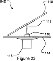
図23及び24は、本発明の別の実施形態による例示としての能動タイル要素84Dを示している。能動タイル要素84Dは、シャフト112に取り付けられたプラットフォーム110を含む。能動タイル要素84Dの傾斜角は固定されている。シャフト112は基板要素114に接続手段116によって回転可能に接続されている。プラットフォーム110と反対側のシャフト112の端部は回転アクチュエータ118に接続されている。回転アクチュエータ118はシャフト112、つまりはプラットフォーム110を制御システム86(図23及び24には示されず)による制御下で回転させることにより、能動タイル要素84Dの配向角を制御する。
23 and 24 illustrate an exemplary
図25は、構造80の能動タイル要素群84を制御する図16の制御システム86が実行する方法300を示すフローチャートである。ブロック302では、制御システム86は、構造80が表示する画像を受信する。ブロック304では、制御システム86は、ブロック302で受信された画像の解像度を調整する必要があるかどうかについて(すなわち、画像がタイル要素84の数とは異なる数の画素を有するかどうかについて)判断する。解像度を調整する必要がある場合(ブロック304のYES出力)、方法300はブロック306に進み、このブロック306で、制御システム86は画像の解像度を調整して構造80の解像度に一致させる。画像が構造80よりも高い解像度を有する場合、画像の複数の画素をまとめてグループ化し、該複数の画素により単一の調整画素を計算により求めて、一つの調整画素を各タイル要素84に対応させるようにすることで、画像の解像度を調整する。画像が構造80よりも低い解像度を有する場合、画像の各画素を複数の調整画素に変換して、一つの調整画素を各タイル要素84に対応させるようにすることで、画像の解像度を調整する。
FIG. 25 is a flowchart illustrating a
画像の解像度を調整する必要がない場合(ブロック304のNO出力)、または画像の解像度がブロック306において調整された後、方法300はブロック308に進む。このブロック308では、制御システム86は、光が構造80に入射する方向(構造80が2以上の光源によって照明される場合は複数の方向)を求める。制御システム86は、光が構造80に入射する方向(1つまたは複数の方向)を、光センサから情報を受信することにより求めることができる。別の構成として、または追加される形で、構造80が外部に位置する状況においては、制御システム86は、1日の時間に基づいて、光が構造80に入射する方向(1つまたは複数の方向)を判定するようにプログラムされる。
If the image resolution does not need to be adjusted (NO output of block 304), or after the image resolution is adjusted at
ブロック310では、制御システム86は、ブロック302で受信された画像の対応する画素群の特性に基づいて、能動タイル要素群84に配向角を割り当てる。ブロック312では、制御システム86は、ブロック310において割り当てられた配向角に能動タイル要素群84を調整する。次に、方法はブロック302に戻って新規画像を受信する。
At
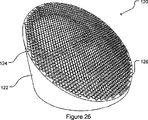
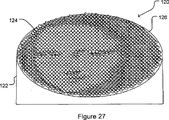
図26及び27は、本発明の別の実施形態による1つのタイル要素120を示している。タイル要素120はせん断円筒122を含み、このせん断円筒122は複数の小型タイル要素124を当該円筒122の表面126上に有する。小型タイル要素群124を使用して、図示の実施形態におけるモナリザのような画像を表面126に表示することができる。
FIGS. 26 and 27 show one
図28は、本発明の別の実施形態による3次元アレイ130を示している。3次元アレイ130は、ライン134に吊り下げられている複数のタイル要素132を含み、該複数のタイル要素132は相互に制御された関係で保持されるようになっている。複数のライン134は複数の列136に並ぶように配置され、各列136のタイル要素群132を使用して3次元画像の2次元スライスを表示する。タイル要素群132は種々のレベルの透明度を有し、アレイ130の中央近傍のタイル要素群132の透明度が最も低く、アレイ130の端部近傍のタイル要素群の透明度が最も高い。別の構成として、タイル要素群132は全て同じレベルの透明度を有することができる。
FIG. 28 illustrates a three-
当業者であれば理解し得るように、上記したような記載を考慮に入れることで、本発明の実施態様は多くの変更及び変形を行なうことができる。例えば、
・図示の実施形態では、タイル要素群は円形表面または楕円形表面を有するが、これらの表面は異なる形状を有することができる。しかしながら、円形表面及び楕円形表面は、特に観察者が異なる観察位置間を移動する場合に、画像がより滑らかに見えるように作用する。
・図示の実施形態の多くでは、基板は矩形であるが、基板は如何なる形状を有することもできる。
・図示の実施形態では、基板は全てほぼ平坦であるが、基板は平坦ではない基板とすることもできる。
As can be appreciated by those skilled in the art, by taking into account the description as described above, embodiments of the present invention can perform Many modifications and variations. For example,
In the illustrated embodiment, the tile elements have a circular surface or an elliptical surface, but these surfaces can have different shapes. However, circular and elliptical surfaces act to make the image appear smoother, especially when the observer moves between different viewing positions.
In many of the illustrated embodiments, the substrate is rectangular, but the substrate can have any shape.
In the illustrated embodiment, the substrates are all substantially flat, but the substrate can be a non-flat substrate.
多数の例示としての態様及び実施形態について説明したが、これらの態様及び実施形態の変形、置き換え、追加及び部分的組み合わせが存在し得ることを当業者は理解し得る。 Although numerous illustrative aspects and embodiments have been described, those skilled in the art will appreciate that variations, substitutions, additions, and partial combinations of these aspects and embodiments may exist.
Claims (37)
互いに固定された関係で保持される複数のタイル要素であって、前記複数のタイル要素の各々は、基準平面に対して或る傾斜角で傾斜されたほぼ平坦な平坦面を含むとともに、前記画像の少なくとも一つの画素に対応し、かつ、前記複数のタイル要素の各々は、光源から当該構造に入射する光の照明方向に対する或る配向角であって、前記基準平面に対する前記平坦面の法線方向の投影像と、前記基準平面に対する前記照明方向と平行な方向の投影像との間の角度として定義される前記配向角を有し、前記配向角は、対応する前記少なくとも一つの画素の明度によって決定される、前記複数のタイル要素を備える、構造。A structure for displaying an image having a plurality of pixels, the structure being
A plurality of tile elements held in a fixed relationship with each other, each of the plurality of tile elements including a substantially flat flat surface inclined at an inclination angle with respect to a reference plane; Each of the plurality of tile elements has a certain orientation angle with respect to an illumination direction of light incident on the structure from a light source, and the normal of the flat surface with respect to the reference plane An orientation angle defined as an angle between a projected image of a direction and a projected image in a direction parallel to the illumination direction relative to the reference plane, the orientation angle being a brightness of the corresponding at least one pixel A structure comprising the plurality of tile elements as determined by.
前記複数のタイル要素は前記基板の表面に接続されている、請求項1記載の構造。Further comprising a substrate having a surface;
The structure of claim 1, wherein the plurality of tile elements are connected to a surface of the substrate.
前記各タイル要素は更に、前記シートにより作製されたタブを含む、請求項2記載の構造。The substrate further includes a sheet,
The structure of claim 2, wherein each tile element further comprises a tab made from the sheet.
前記各タイル要素は、前記光媒質中の光透過防止領域を含む、請求項2記載の構造。The substrate includes an optical medium;
The structure according to claim 2, wherein each tile element includes a light transmission preventing region in the optical medium.
前記各タイル要素は更に、前記複数の鋸歯状開口のうちの一つと係合するように適合させた鋸歯状の基台を有するせん断円筒を含む、請求項2記載の構造。The substrate further includes a plurality of serrated openings,
The structure of claim 2, wherein each tile element further comprises a shear cylinder having a serrated base adapted to engage one of the plurality of serrated openings.
請求項13記載の構造を、光源を収容するハウジングの内部に備える表示装置。A display device,
A display device comprising the structure according to claim 13 in a housing that houses a light source.
前記複数の突起は、前記光源からの光が前記構造により屈折されて前記画像が表示されるように、前記ハウジングの内部に向かって突出している、請求項16記載の表示装置。The structure is integral with the wall of the housing;
The display device according to claim 16, wherein the plurality of protrusions protrude toward the inside of the housing so that light from the light source is refracted by the structure and the image is displayed.
前記表面を有する前記基板を設けること、
前記基板上に、前記基板の表面にほぼ垂直に延在するように複数の前記突起を形成すること、
対応する前記少なくとも一つの画素の明度に基づいて、前記配向角を前記複数の突起の各々に割り当てること、
前記複数の突起の各々を前記配向角に沿った方向で下方に向かって切断することにより、前記基板の表面に対して鋭角で傾斜するほぼ平坦な端部表面を形成すること、
を備える方法。A method for creating a structure according to claim 3, comprising:
Providing the substrate having the surface;
Forming a plurality of protrusions on the substrate so as to extend substantially perpendicular to the surface of the substrate;
Assigning the orientation angle to each of the plurality of protrusions based on the brightness of the corresponding at least one pixel;
Cutting each of the plurality of protrusions downward in a direction along the orientation angle to form a substantially flat end surface inclined at an acute angle with respect to the surface of the substrate;
A method comprising:
前記複数の突起に光が入射する方向を求めること、
前記光が入射する方向に対して−180度〜+180度の範囲で或る値を前記各突起に前記配向角として割り当てることであって、前記少なくとも一つの対応する画素に関する突起の明るさが最大のときには、その突起に0度の値を前記配向角として割り当てるとともに、前記少なくとも一つの対応する画素に関する突起の明るさが最小のときには、その突起に±180度の値を前記配向角として割り当てること、
を含む、請求項20記載の方法。Assigning the orientation angle to each of the plurality of protrusions;
Obtaining a direction in which light is incident on the plurality of protrusions;
Assigning a certain value to each of the protrusions as the orientation angle in a range of −180 degrees to +180 degrees with respect to the incident direction of light, and the brightness of the protrusions related to the at least one corresponding pixel is maximized In this case, a value of 0 degree is assigned to the protrusion as the orientation angle, and when the brightness of the protrusion relating to the at least one corresponding pixel is minimum, a value of ± 180 degrees is assigned to the protrusion as the orientation angle. ,
21. The method of claim 20, comprising:
複数の凹部を内部に有する基台であって、該各凹部が前記複数の突起の一つに対応している、基台と、
前記基台から上に向かって延びて容積を区画する壁と、
前記複数の凹部の各々に位置する円筒状プラグであって、成形材料を前記容積内に充填して硬化させることにより前記構造を製作することができるように、前記円筒状プラグは対応する前記タイル要素の配向角に従って制御可能に回転される、円筒状プラグと、
を備える装置。An apparatus for creating the structure of claim 4, comprising:
A base having a plurality of recesses therein, each base corresponding to one of the plurality of protrusions;
A wall extending upward from the base and defining a volume;
A cylindrical plug located in each of the plurality of recesses, wherein the cylindrical plug corresponds to the tile so that the structure can be fabricated by filling the volume with a molding material and curing. A cylindrical plug that is controllably rotated according to the orientation angle of the element;
A device comprising:
前記成形材料は前記容積内に注ぎ込まれる、方法。A method of using the apparatus of claim 23, comprising:
The method wherein the molding material is poured into the volume.
前記成形材料は前記容積内に圧入される、方法。A method of using the apparatus of claim 23, comprising:
The method wherein the molding material is pressed into the volume.
前記成形材料は、前記容積内の圧力を減圧することにより前記容積内に吸引される、方法。A method of using the apparatus of claim 23, comprising:
The method wherein the molding material is sucked into the volume by reducing the pressure within the volume.
前記成形材料は、熱可塑性樹脂のエンボス加工により前記容積内に充填される、方法。A method of using the apparatus of claim 23, comprising:
The method wherein the molding material is filled into the volume by embossing a thermoplastic resin.
前記成形材料は、熱可塑性樹脂の成形加工により前記容積内に充填される、方法。A method of using the apparatus of claim 23, comprising:
The method wherein the molding material is filled into the volume by a thermoplastic resin molding process.
互いに制御される関係で保持される複数のタイル要素であって、前記複数のタイル要素の各々は、基準平面に対して或る傾斜角で傾斜されたほぼ平坦な平坦面を含むとともに、前記画像の少なくとも一つの画素に対応し、かつ、前記複数のタイル要素の各々は、光源から当該構造に入射する光の照明方向に対する或る配向角であって、前記基準平面に対する前記平坦面の法線方向の投影像と、前記基準平面に対する前記照明方向と平行な方向の投影像との間の角度として定義される前記配向角を有し、前記配向角は、対応する前記少なくとも一つの画素の明度によって決定される、前記複数のタイル要素と、
制御システムによる制御下で前記複数のタイル要素の配向角を動的に変化させるための複数のアクチュエータであって、前記各アクチュエータは、前記各タイル要素を動作させるべく前記複数のタイル要素の一つに接続されており、前記各タイル要素は複数の異なる前記配向角のいずれか一つを有するように動作する、前記複数のアクチュエータと、
を備える構造。A structure for displaying an image having a plurality of pixels, the structure being
A plurality of tile elements held in a controlled relationship with each other, each of the plurality of tile elements including a substantially flat flat surface inclined at an angle of inclination with respect to a reference plane; Each of the plurality of tile elements has a certain orientation angle with respect to an illumination direction of light incident on the structure from a light source, and the normal of the flat surface with respect to the reference plane An orientation angle defined as an angle between a projected image of a direction and a projected image in a direction parallel to the illumination direction relative to the reference plane, the orientation angle being a brightness of the corresponding at least one pixel The plurality of tile elements, determined by:
A plurality of actuators for dynamically changing an orientation angle of the plurality of tile elements under control of a control system, wherein each actuator is one of the plurality of tile elements to operate each tile element; A plurality of actuators connected to each other, each tile element operating to have any one of a plurality of different orientation angles;
With a structure.
前記各アクチュエータは更に、前記複数の突起のうちの対応する一つを回転させるように接続された回転アクチュエータを含む、請求項29記載の構造。Each tile element further includes a protrusion protruding from the surface of the substrate;
30. The structure of claim 29, wherein each actuator further comprises a rotary actuator connected to rotate a corresponding one of the plurality of protrusions.
前記各アクチュエータは更に、複数の前記シャフトのうちの対応する一つを回転させるように接続された回転アクチュエータを含む、請求項29記載の構造。Each tile element further includes a platform connected to the shaft;
30. The structure of claim 29, wherein each actuator further comprises a rotary actuator connected to rotate a corresponding one of the plurality of shafts.
前記各アクチュエータは更に、前記カップ内に位置し、かつ電流を流して磁界を生成することにより前記複数のタイル要素のうちの対応する一つの傾斜角及び配向角を制御するように接続された少なくとも3つのコイルを含む、請求項30記載の構造。Each tile element further includes a spherical portion held in the cup by a holding means, the spherical portion having a magnet therein;
Each actuator is further positioned within the cup and connected to control a tilt angle and orientation angle of a corresponding one of the plurality of tile elements by passing a current to generate a magnetic field. 32. The structure of claim 30, comprising three coils.
前記各アクチュエータは更に、前記基台内に位置し、かつ電流を流して磁界を生成することにより前記複数のタイル要素のうちの対応する一つの傾斜角及び配向角を制御するように接続された少なくとも3つのコイルを含む、請求項30記載の構造。Each tile element is further a platform rotatably mounted on a base, the platform having a shaft extending from the platform to the interior of the base cavity, the shaft opposite the platform. The platform having a magnet at the end of the shaft,
Each actuator is further located within the base and connected to control a corresponding tilt angle and orientation angle of the plurality of tile elements by passing a current to generate a magnetic field. 32. The structure of claim 30, comprising at least three coils.
互いに制御される関係で保持される複数のタイル要素を形成することであって、該複数のタイル要素の各々は、前記複数の画素の少なくとも一つに対応し、かつほぼ平坦な平坦面を有する、前記複数のタイル要素を形成すること、
光の入射方向を求めること、
前記平坦面が基準平面に対して或る傾斜角で傾斜するように、かつ前記基準平面に対する前記平坦面の法線方向の投影像と、前記基準平面に対する前記光の入射方向の投影像とによって前記配向角が定義されるように、前記各タイル要素を配向させること、
を備え、
前記各タイル要素の配向角は、前記対応する少なくとも一つの画素の明度によって決定される、方法。A method for displaying an image having a plurality of pixels, wherein:
Forming a plurality of tile elements that are held in a controlled relationship with each other, each of the plurality of tile elements corresponding to at least one of the plurality of pixels and having a substantially flat surface. Forming the plurality of tile elements;
Obtaining the direction of incidence of light,
A projection image in the normal direction of the flat surface with respect to the reference plane and a projection image in the incident direction of the light with respect to the reference plane so that the flat surface is inclined at a certain inclination angle with respect to the reference plane. Orienting each tile element such that the orientation angle is defined;
With
The orientation angle of each tile element is determined by the brightness of the corresponding at least one pixel.
Applications Claiming Priority (2)
| Application Number | Priority Date | Filing Date | Title |
|---|---|---|---|
| US58205504P | 2004-06-23 | 2004-06-23 | |
| PCT/CA2005/000972 WO2006000087A1 (en) | 2004-06-23 | 2005-06-21 | Sculptural imaging with optical tiles |
Publications (2)
| Publication Number | Publication Date |
|---|---|
| JP2008503777A JP2008503777A (en) | 2008-02-07 |
| JP4615563B2 true JP4615563B2 (en) | 2011-01-19 |
Family
ID=35781541
Family Applications (1)
| Application Number | Title | Priority Date | Filing Date |
|---|---|---|---|
| JP2007516925A Expired - Fee Related JP4615563B2 (en) | 2004-06-23 | 2005-06-21 | Sculpture photography using optical tiles |
Country Status (9)
| Country | Link |
|---|---|
| US (3) | US8218227B2 (en) |
| EP (1) | EP1782409B1 (en) |
| JP (1) | JP4615563B2 (en) |
| CN (1) | CN100476499C (en) |
| AT (1) | ATE523871T1 (en) |
| AU (1) | AU2005256202B2 (en) |
| CA (1) | CA2578203C (en) |
| ES (1) | ES2368929T3 (en) |
| WO (1) | WO2006000087A1 (en) |
Families Citing this family (23)
| Publication number | Priority date | Publication date | Assignee | Title |
|---|---|---|---|---|
| CN100476499C (en) | 2004-06-23 | 2009-04-08 | 艺术科学魁恩传媒公司 | Sculptural imaging with optical tiles |
| CN101493212B (en) * | 2008-04-03 | 2011-01-12 | 嘉力时灯光设备(东莞)有限公司 | Decoration module and decoration apparatus thereof |
| US9071834B2 (en) * | 2009-04-25 | 2015-06-30 | James Yett | Array of individually angled mirrors reflecting disparate color sources toward one or more viewing positions to construct images and visual effects |
| US8182896B2 (en) * | 2009-10-05 | 2012-05-22 | Dri-Design, Llc | Method and apparatus for making optical tiles |
| KR101748180B1 (en) * | 2010-12-31 | 2017-06-16 | 주식회사 케이티 | Method and apparatus of measuring size of object in image |
| CN103576649B (en) * | 2013-10-16 | 2015-12-23 | 中国航天科技集团公司第九研究院第七七一研究所 | A kind of dynamic screen system and control method thereof |
| KR101606738B1 (en) | 2014-11-24 | 2016-03-28 | 정재희 | Imaging tiles of sculptural imaging plate coated with anti-fouling paint |
| KR20170080674A (en) | 2014-12-10 | 2017-07-10 | 도판 인사츠 가부시키가이샤 | Embossed sheet and decorative sheet |
| KR101663757B1 (en) * | 2015-11-27 | 2016-10-17 | (주)이케이엘이디 | Solar-powered self luminous traffic signs |
| KR101608004B1 (en) | 2015-12-18 | 2016-03-31 | 최경미 | Image plate for embodying detailed image |
| EP3557563B1 (en) * | 2016-12-19 | 2021-11-17 | P&I System | Three-dimensional advertisement device |
| EP3704531B1 (en) | 2017-11-02 | 2023-12-06 | InterDigital Madison Patent Holdings, SAS | Method and system for aperture expansion in light field displays |
| US10571683B2 (en) * | 2017-11-28 | 2020-02-25 | Aptiv Technologies Limited | Multi-faceted MEMS mirror device useful for vehicle LIDAR |
| KR102219121B1 (en) * | 2018-07-20 | 2021-02-24 | (주)다스콘 | Method and apparatus for surface display using void mechanism |
| KR20210066797A (en) * | 2018-08-29 | 2021-06-07 | 피씨엠에스 홀딩스, 인크. | Optical method and system for light field display based on mosaic periodic layer |
| JP7065764B2 (en) * | 2018-12-28 | 2022-05-12 | 本田技研工業株式会社 | Interior materials for vehicles |
| USD906697S1 (en) * | 2019-04-03 | 2021-01-05 | Patricia Witkowski | Punched out paper sheet |
| KR102195539B1 (en) * | 2019-05-10 | 2020-12-29 | (주)엑스오비스 | Method and device for controlling arrangement states of three dimensional units |
| USD943291S1 (en) * | 2020-01-10 | 2022-02-15 | Wall Stories | Wallpaper strip |
| USD944542S1 (en) * | 2020-03-16 | 2022-03-01 | Gpcp Ip Holdings Llc | Paper product with an embossing pattern |
| US11702797B2 (en) | 2020-03-16 | 2023-07-18 | Gpcp Ip Holdings Llc | Tissue products formed from multi-apex emboss elements and methods for producing the same |
| US11441274B2 (en) | 2020-03-16 | 2022-09-13 | Gpcp Ip Holdings Llc | Tissue products having emboss elements with reduced bunching and methods for producing the same |
| AU2021221691A1 (en) * | 2021-08-25 | 2023-03-02 | Metrix Group Pty Ltd | Perforated imaging with variable openings |
Family Cites Families (22)
| Publication number | Priority date | Publication date | Assignee | Title |
|---|---|---|---|---|
| JPH0823499A (en) | 1994-07-11 | 1996-01-23 | Canon Inc | Image display device |
| JPH08251520A (en) * | 1995-03-08 | 1996-09-27 | Nikon Corp | Video projector |
| US5870097A (en) * | 1995-08-04 | 1999-02-09 | Microsoft Corporation | Method and system for improving shadowing in a graphics rendering system |
| US5889568A (en) * | 1995-12-12 | 1999-03-30 | Rainbow Displays Inc. | Tiled flat panel displays |
| US6243059B1 (en) * | 1996-05-14 | 2001-06-05 | Rainbow Displays Inc. | Color correction methods for electronic displays |
| US6042241A (en) * | 1997-07-31 | 2000-03-28 | Litton Systems, Inc. | Backlight with integral illumination source |
| US6154302A (en) * | 1997-11-15 | 2000-11-28 | Canon Kabushiki Kaisha | Light deflection device and array thereof |
| US6624823B2 (en) * | 1998-02-17 | 2003-09-23 | Sun Microsystems, Inc. | Graphics system configured to determine triangle orientation by octant identification and slope comparison |
| SE9800665D0 (en) * | 1998-03-02 | 1998-03-02 | Micronic Laser Systems Ab | Improved method for projection printing using a micromirror SLM |
| US6570578B1 (en) * | 1998-04-03 | 2003-05-27 | Avid Technology, Inc. | System for automatic generation of selective partial renderings of complex scenes |
| US6771264B1 (en) * | 1998-08-20 | 2004-08-03 | Apple Computer, Inc. | Method and apparatus for performing tangent space lighting and bump mapping in a deferred shading graphics processor |
| US6553138B2 (en) * | 1998-12-30 | 2003-04-22 | New York University | Method and apparatus for generating three-dimensional representations of objects |
| US6552734B1 (en) * | 1999-04-29 | 2003-04-22 | Smoothware Design | System and method for generating a composite image based on at least two input images |
| JP2002122809A (en) * | 2000-10-18 | 2002-04-26 | Canon Inc | Projection type display device |
| CA2442514A1 (en) | 2001-03-30 | 2002-10-10 | Gsi Lumonics Corporation | Method and apparatus for orienting a surface |
| US6956687B2 (en) * | 2001-04-03 | 2005-10-18 | Cidra Corporation | Optical blocking filter having an array of micro-mirrors |
| US6829092B2 (en) * | 2001-08-15 | 2004-12-07 | Silicon Light Machines, Inc. | Blazed grating light valve |
| US6857751B2 (en) * | 2002-12-20 | 2005-02-22 | Texas Instruments Incorporated | Adaptive illumination modulator |
| JP4452560B2 (en) * | 2004-06-07 | 2010-04-21 | 富士フイルム株式会社 | Transmission type light modulation element and transmission type light modulation array element |
| US7787170B2 (en) * | 2004-06-15 | 2010-08-31 | Texas Instruments Incorporated | Micromirror array assembly with in-array pillars |
| CN100476499C (en) | 2004-06-23 | 2009-04-08 | 艺术科学魁恩传媒公司 | Sculptural imaging with optical tiles |
| JP4730836B2 (en) * | 2005-09-15 | 2011-07-20 | Jfeスチール株式会社 | Apparatus and method for measuring surface distortion |
-
2005
- 2005-06-21 CN CNB2005800207858A patent/CN100476499C/en not_active Expired - Fee Related
- 2005-06-21 CA CA2578203A patent/CA2578203C/en active Active
- 2005-06-21 US US11/570,589 patent/US8218227B2/en active Active
- 2005-06-21 JP JP2007516925A patent/JP4615563B2/en not_active Expired - Fee Related
- 2005-06-21 WO PCT/CA2005/000972 patent/WO2006000087A1/en active Application Filing
- 2005-06-21 ES ES05759482T patent/ES2368929T3/en active Active
- 2005-06-21 AU AU2005256202A patent/AU2005256202B2/en active Active
- 2005-06-21 EP EP05759482A patent/EP1782409B1/en active Active
- 2005-06-21 AT AT05759482T patent/ATE523871T1/en not_active IP Right Cessation
-
2012
- 2012-07-06 US US13/543,674 patent/US8837034B2/en active Active
-
2014
- 2014-09-04 US US14/477,202 patent/US9759906B2/en active Active
Also Published As
| Publication number | Publication date |
|---|---|
| ES2368929T3 (en) | 2011-11-23 |
| WO2006000087A1 (en) | 2006-01-05 |
| CN101002242A (en) | 2007-07-18 |
| CA2578203A1 (en) | 2006-01-05 |
| US9759906B2 (en) | 2017-09-12 |
| ATE523871T1 (en) | 2011-09-15 |
| CN100476499C (en) | 2009-04-08 |
| US20120275010A1 (en) | 2012-11-01 |
| CA2578203C (en) | 2014-03-11 |
| US20150043096A1 (en) | 2015-02-12 |
| US20080301986A1 (en) | 2008-12-11 |
| EP1782409B1 (en) | 2011-09-07 |
| US8218227B2 (en) | 2012-07-10 |
| AU2005256202B2 (en) | 2010-06-10 |
| JP2008503777A (en) | 2008-02-07 |
| EP1782409A1 (en) | 2007-05-09 |
| EP1782409A4 (en) | 2007-07-18 |
| US8837034B2 (en) | 2014-09-16 |
| AU2005256202A1 (en) | 2006-01-05 |
Similar Documents
| Publication | Publication Date | Title |
|---|---|---|
| JP4615563B2 (en) | Sculpture photography using optical tiles | |
| US11553172B2 (en) | Precision multi-view display | |
| US11882265B1 (en) | Array of individually angled mirrors reflecting disparate color sources toward one or more viewing positions to construct images and visual effects | |
| US7703924B2 (en) | Systems and methods for displaying three-dimensional images | |
| US20040021802A1 (en) | Color 3D image display | |
| WO2020080111A1 (en) | Image display device | |
| CN110657376B (en) | Lighting device | |
| WO2017206724A1 (en) | Decorative member, cover plate for electronic apparatus, and electronic apparatus | |
| US20200086674A1 (en) | Optical structure | |
| US20050237622A1 (en) | Color 3D image display | |
| JP2007279741A (en) | High-resolution scanning display system | |
| JPWO2018043204A1 (en) | Display device | |
| TW201636685A (en) | Presentation apparatus and video presentation method | |
| CN107454778B (en) | Decorative sheet, electronic device cover plate and electronic device | |
| JP2003216071A (en) | Rotary type display device | |
| KR101601212B1 (en) | 3Dimensional Display System Based on Pseudo hologram | |
| WO2007052261A2 (en) | A screen projection system | |
| CN108535879A (en) | It shows equipment and shows the driving method and device of equipment | |
| WO2011058107A1 (en) | A method, device and system for reducing speckle contrast | |
| KR20220109223A (en) | System and method for constructing media facade using projection mapping technology |
Legal Events
| Date | Code | Title | Description |
|---|---|---|---|
| A621 | Written request for application examination |
Free format text: JAPANESE INTERMEDIATE CODE: A621 Effective date: 20080618 |
|
| A131 | Notification of reasons for refusal |
Free format text: JAPANESE INTERMEDIATE CODE: A131 Effective date: 20100608 |
|
| A521 | Request for written amendment filed |
Free format text: JAPANESE INTERMEDIATE CODE: A523 Effective date: 20100830 |
|
| TRDD | Decision of grant or rejection written | ||
| A01 | Written decision to grant a patent or to grant a registration (utility model) |
Free format text: JAPANESE INTERMEDIATE CODE: A01 Effective date: 20100921 |
|
| A01 | Written decision to grant a patent or to grant a registration (utility model) |
Free format text: JAPANESE INTERMEDIATE CODE: A01 |
|
| A61 | First payment of annual fees (during grant procedure) |
Free format text: JAPANESE INTERMEDIATE CODE: A61 Effective date: 20101020 |
|
| R150 | Certificate of patent or registration of utility model |
Ref document number: 4615563 Country of ref document: JP Free format text: JAPANESE INTERMEDIATE CODE: R150 Free format text: JAPANESE INTERMEDIATE CODE: R150 |
|
| FPAY | Renewal fee payment (event date is renewal date of database) |
Free format text: PAYMENT UNTIL: 20131029 Year of fee payment: 3 |
|
| R250 | Receipt of annual fees |
Free format text: JAPANESE INTERMEDIATE CODE: R250 |
|
| R250 | Receipt of annual fees |
Free format text: JAPANESE INTERMEDIATE CODE: R250 |
|
| R250 | Receipt of annual fees |
Free format text: JAPANESE INTERMEDIATE CODE: R250 |
|
| R250 | Receipt of annual fees |
Free format text: JAPANESE INTERMEDIATE CODE: R250 |
|
| R250 | Receipt of annual fees |
Free format text: JAPANESE INTERMEDIATE CODE: R250 |
|
| R250 | Receipt of annual fees |
Free format text: JAPANESE INTERMEDIATE CODE: R250 |
|
| R250 | Receipt of annual fees |
Free format text: JAPANESE INTERMEDIATE CODE: R250 |
|
| LAPS | Cancellation because of no payment of annual fees |