JP4613643B2 - Temperature measuring device - Google Patents
Temperature measuring device Download PDFInfo
- Publication number
- JP4613643B2 JP4613643B2 JP2005061363A JP2005061363A JP4613643B2 JP 4613643 B2 JP4613643 B2 JP 4613643B2 JP 2005061363 A JP2005061363 A JP 2005061363A JP 2005061363 A JP2005061363 A JP 2005061363A JP 4613643 B2 JP4613643 B2 JP 4613643B2
- Authority
- JP
- Japan
- Prior art keywords
- measurement
- temperature
- resistance
- value
- auxiliary
- Prior art date
- Legal status (The legal status is an assumption and is not a legal conclusion. Google has not performed a legal analysis and makes no representation as to the accuracy of the status listed.)
- Expired - Fee Related
Links
Images

Landscapes
- Measuring Temperature Or Quantity Of Heat (AREA)
- Measurement Of Resistance Or Impedance (AREA)
Description
本発明は、温度計測装置に関するものである。 The present invention relates to a temperature measuring device.
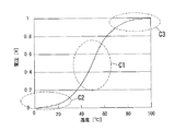
従来、この種の温度計測装置は、測定対象の温度が線形的に変化するのに対して抵抗値が略指数関数的に変化する測温抵抗体(図2参照)と、測温抵抗体と直列に接続する1つの定抵抗と、略等間隔的な電圧の変化を読み取るADコンバータ(AD変換器)等を含む制御部とを備え、測温抵抗体の両端電圧に基づいて測定温度を算出する。ところが、測温抵抗体の抵抗値が非線形に変化することにより、測温抵抗体の両端電圧において、高分解能領域(細かい変化まで読み取れる領域)と低分解能領域(粗い変化しか読み取れない領域)の差が大きくなって表れてしまうという問題があった。また、定抵抗の両端電圧に基づいて測定温度を算出する温度計測装置の場合も、図7に示すように、定抵抗の両端電圧において、高分解能領域(図7のC1)と低分解能領域(図7のC2,C3)の差が大きくなって表れてしまうという問題があった。例えば、定抵抗の抵抗値を5.15kΩとした場合、低分解能領域における定抵抗の両端電圧の変化率は約0.6mV/℃である。 Conventionally, this type of temperature measuring device includes a resistance temperature detector (see FIG. 2) whose resistance value changes approximately exponentially while the temperature of the object to be measured changes linearly, and a resistance temperature detector, Equipped with one constant resistor connected in series and a control unit including an AD converter (AD converter) that reads changes in voltage at approximately equal intervals, and calculates the measured temperature based on the voltage across the resistance temperature detector To do. However, the resistance value of the resistance temperature detector changes in a non-linear manner, resulting in a difference between the high resolution area (area where fine changes can be read) and the low resolution area (area where only coarse changes can be read). There was a problem that appeared large. Further, in the case of a temperature measuring device that calculates the measured temperature based on the voltage across the constant resistance, as shown in FIG. 7, the high resolution region (C1 in FIG. 7) and the low resolution region ( There is a problem that the difference between C2 and C3) in FIG. For example, when the resistance value of the constant resistance is 5.15 kΩ, the rate of change of the voltage across the constant resistance in the low resolution region is about 0.6 mV / ° C.
上記問題を解決するために、低分解能領域を低減し、全ての温度範囲で一定以上の測定分解能を有する温度計測装置が提供されている。例えば、特許文献1には、制御装置により、現在の温度が、測定分解能の低い高温領域に達したと判断した場合、測温抵抗体と直列に接続する定抵抗(固定抵抗体)の直列回路のうち、抵抗値の低い定抵抗が属する直列回路を選択的に閉止(オン)するように複数のスイッチ手段の開閉状態をそれぞれ制御する温度計測装置が開示されている。これにより、出力電圧の温度特性は、測定分解能を改善し得る急な傾きに変更されるので、温度が線形的に高くなるにつれて抵抗値が略指数関数的に減少する測温抵抗体を用いた場合であっても、高温領域の測定分解能が改善し測定温度を算出することができる。また、特許文献2には、測温抵抗体を用い、換算表を記憶して測定温度を補正する温度計測装置(温度測定装置)が開示されている。
しかしながら、上記特許文献1の温度計測装置は、低分解能領域である場合に定抵抗を切り替えているが、各定抵抗に対応する測定領域毎に測定分解能の最適化がされていないので、測定分解能が低下する毎に新たな定抵抗を追加しなければならないという問題があった。また、2つの測定領域の間には、滑らかに変化させるために不感帯(温度が変化しても電圧値の変化として読み取ることができない領域)を設けているので、精度が悪くなるという問題もあった。
However, although the temperature measurement device of
本発明は上記の点に鑑みて為されたものであり、その目的とするところは、不感帯を設けることなく測定分解能を効率よく上げることができる温度計測装置を提供することにある。 The present invention has been made in view of the above points, and an object of the present invention is to provide a temperature measurement device capable of efficiently increasing measurement resolution without providing a dead zone.
請求項1に記載の発明は、温度が線形的に変化すると抵抗値が略指数関数的に変化する測温抵抗体と、両端温度における前記測温抵抗体の抵抗値が等比級数的になるように、予め決められた温度領域を複数の測定領域に分割し、測定値を入力し、前記測定値に基づいて、測定温度を算出するか、又は前記測定領域を切り替えて前記測定値を再入力するかの判断を行う制御手段と、それぞれ異なる前記測定領域と対応し、対応する測定領域における前記測温抵抗体の最小値と最大値との間の大きさの抵抗値を有する複数の定抵抗と、隣接する測定領域に対応する2つの定抵抗の抵抗値の積の略平方根値を抵抗値とする補助抵抗とを備え、前記制御手段は、前記複数の定抵抗と前記補助抵抗とを選択的に前記測温抵抗体と直列に接続させる機能を有し、前記隣接する測定領域のうち予め決められた範囲の補助測定領域において、前記隣接する測定領域に対応する2つの定抵抗の両端電圧を前記測定値として入力し当該測定値に基づいて前記定抵抗による仮測定温度を算出し、前記補助抵抗の両端電圧を前記測定値として入力し当該測定値に基づいて前記補助抵抗による仮測定温度を算出し、前記定抵抗による仮測定温度と前記補助抵抗による仮測定温度との平均値を前記測定温度とすることを特徴とする。 According to the first aspect of the present invention, the resistance value of the resistance temperature sensor changes approximately exponentially when the temperature changes linearly, and the resistance value of the resistance temperature sensor at both end temperatures becomes a geometric series. As described above, a predetermined temperature region is divided into a plurality of measurement regions, and a measurement value is input, and a measurement temperature is calculated based on the measurement value, or the measurement value is regenerated by switching the measurement region. Control means for determining whether to input, a plurality of constant values corresponding to the different measurement areas , each having a resistance value having a magnitude between the minimum value and the maximum value of the resistance temperature detector in the corresponding measurement area. A resistance , and an auxiliary resistance having a resistance value that is approximately the square root of the product of the resistance values of two constant resistances corresponding to adjacent measurement regions, and the control means includes the plurality of constant resistances and the auxiliary resistance. The function of selectively connecting in series with the resistance temperature detector Then, in the auxiliary measurement region in a predetermined range among the adjacent measurement regions, voltages at both ends of two constant resistances corresponding to the adjacent measurement regions are input as the measurement values, and the constant measurement is performed based on the measurement values. A temporary measurement temperature by resistance is calculated, a voltage across the auxiliary resistor is input as the measurement value, a temporary measurement temperature by the auxiliary resistance is calculated based on the measurement value, and a temporary measurement temperature by the constant resistance and the auxiliary resistance are calculated. The average value with the temporary measurement temperature is used as the measurement temperature .
この構成では、各測定領域において対応する定抵抗の両端電圧の温度変化に対する変化率を大きくすることができるので、不感帯を設けることなく測定分解能を効率よく上げることができる。この構成では、補助測定領域の最も測定分解能の高い部分を測定領域の境界近傍に設定することができるので、測定分解能を上げることができる。また、白色性の読み取り誤差が発生した場合であっても、定抵抗による仮測定温度と、補助抵抗による仮測定温度との平均値により、上記誤差要因を低減することができる。 In this configuration, since the rate of change of the corresponding constant resistance with respect to the temperature change in each measurement region can be increased, the measurement resolution can be increased efficiently without providing a dead zone. In this configuration, the portion with the highest measurement resolution in the auxiliary measurement region can be set near the boundary of the measurement region, so that the measurement resolution can be increased. Even when a white reading error occurs, the error factor can be reduced by an average value of the temporary measurement temperature by the constant resistance and the temporary measurement temperature by the auxiliary resistance.
請求項2に記載の発明は、請求項1に記載の発明において、前記制御手段が、前記予め決められた温度領域を3以上の前記測定領域に分割し、前記複数の定抵抗の抵抗値が、等比級数的になることを特徴とする。この構成では、複数の定抵抗の抵抗値が等比級数的に設定されるので、測定分解能をさらに上げることができる。 According to a second aspect of the present invention, in the first aspect of the present invention, the control unit divides the predetermined temperature region into three or more measurement regions, and the resistance values of the plurality of constant resistances are determined. It is characterized by being a geometric series. In this configuration, the resistance values of the plurality of constant resistances are set in a geometric series, so that the measurement resolution can be further increased.
請求項3に記載の発明は、請求項1又は2に記載の発明において、前記各定抵抗の抵抗値が、前記対応する測定領域の中間温度における前記測温抵抗体の抵抗値と略等しいことを特徴とする。この構成では、各定抵抗の両端電圧の大きさの範囲を略同一にすることができるので、測定分解能をさらに上げることができる。また、各測定領域内の高温側と低温側との測定分解能を等しくすることができる。
The invention according to
請求項4に記載の発明は、請求項1〜3のいずれかに記載の発明において、前記制御手段が、隣接する測定領域のうち予め決められた範囲の境界領域において、前記隣接する測定領域に対応する2つの定抵抗の両端電圧を前記測定値として入力し、入力された各測定値に基づいて定抵抗による仮測定温度を算出し、算出された2つの定抵抗による仮測定温度に対し、それぞれ他の測定領域側に近づくにつれて小さくなるように設定された重みをつけ、重みをつけられた2つの定抵抗による仮測定温度の平均値を前記測定温度とすることを特徴とする。この構成では、測定領域を越えて温度を計測する場合に、ユーザが測定領域の境界を意識することなく測定温度を算出することができる。また、不感帯を完全に防止するので、境界領域付近でもさらに高精度に測定温度を測定することができる。 According to a fourth aspect of the present invention, in the invention according to any one of the first to third aspects of the present invention, the control means is arranged in the boundary region of a predetermined range among the adjacent measurement regions, in the adjacent measurement region. The voltage across the two corresponding constant resistances is input as the measurement value, and the temporary measurement temperature by the constant resistance is calculated based on each input measurement value. For the calculated temporary measurement temperature by the two constant resistances, A weight set so as to become smaller as it approaches each other measurement region side is given, and an average value of provisional measurement temperatures by two weighted constant resistances is set as the measurement temperature. With this configuration, when the temperature is measured beyond the measurement area, the measurement temperature can be calculated without the user being aware of the boundary of the measurement area. In addition, the you completely prevent dead zone, it is possible to measure the measured temperature with higher accuracy in the vicinity of the boundary region.
請求項5に記載の発明は、請求項1に記載の発明において、隣接する測定領域の全てに前記補助抵抗を備え、前記制御手段が、前記隣接する測定領域のうち予め決められた範囲の補助測定領域の全てにおいて、前記判断を行うことを特徴とする。この構成では、隣接する測定領域の全てにおいて、補助測定領域の最も測定分解能の高い部分を測定領域の境界近傍に設定することができるので、測定分解能を上げることができる。 According to a fifth aspect of the present invention, in the first aspect of the present invention, the auxiliary resistance is provided in all of the adjacent measurement areas, and the control means assists a predetermined range of the adjacent measurement areas. The determination is performed in all measurement areas. In this configuration, in all the adjacent measurement areas, the portion with the highest measurement resolution of the auxiliary measurement area can be set near the boundary of the measurement area, so that the measurement resolution can be increased.
請求項6に記載の発明は、請求項1又は5に記載の発明において、前記制御手段が、隣接する補助測定領域のうち予め決められた範囲の補助境界領域において、前記隣接する補助測定領域に対応する2つの補助抵抗の両端電圧を前記測定値として入力し、入力された各測定値に基づいて補助抵抗による仮測定温度を算出し、算出された2つの前記補助抵抗による仮測定温度に対し、それぞれ他の補助測定領域側に近づくにつれて小さくなるように設定された重みをつけ、重みをつけられた2つの補助抵抗による仮測定温度の平均値と、前記定抵抗の両端電圧である測定値に基づいて算出される定抵抗による仮測定温度との平均値を前記測定温度とすることを特徴とする。この構成では、補助測定領域の境界温度を越えて温度を計測する場合に、温度変化に対して測定値を滑らかに変化させることができるので、ユーザが補助測定領域の境界を意識することなく測定温度を算出することができる。また、不感帯が存在しないので、補助境界領域付近でも高精度に測定温度を測定することができる。
The invention according to claim 6 is the invention according to
請求項7に記載の発明は、請求項1〜6のいずれかに記載の発明において、前記制御手段は、標準電圧と前記測定値とを切り替えて入力し、前記標準電圧と前記測定値とから前記測定温度を算出することを特徴とする。
The invention according to
本発明によれば、不感帯を設けることなく測定分解能を効率よく上げることができる。 According to the present invention, the measurement resolution can be efficiently increased without providing a dead zone.
(基本形態)
先ず、基本形態の基本的な構成について図1〜4を用いて説明する。基本形態の温度計測装置は、図1に示すように、測温抵抗体1と、複数の定抵抗2と、制御部3とを備えている。
( Basic form )
First, a basic configuration of the basic form will be described with reference to FIGS. As shown in FIG. 1, the basic form temperature measuring apparatus includes a
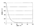
測温抵抗体1は、例えばNTC(Negative Temperature Coefficient)のサーミスタ等であり、一端側で直流電圧源(図示せず)と接続し、他端側で複数の定抵抗2と接続している。直流電圧源は直流電圧Vccを供給するものである。上記測温抵抗体1は、図2に示すように、測定対象の温度が線形的に高くなるにつれて抵抗値が略指数関数的に減少する特性を有している。基本形態の測温抵抗体1の抵抗値は、0℃のときが1000kΩであり、1℃上昇する毎に0.9倍になり、100℃のときが0.0265kΩとなる。上記測温抵抗体1の温度測定範囲は0〜100℃である。なお、測温抵抗体1の抵抗値及び温度測定範囲は、上記に限定されるものではなく、用途に応じて適宜選択するものである。
The
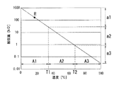
複数の定抵抗2は、図1に示すように、3つの定抵抗20,21,22を備えている。各定抵抗20,21,22は、一端側で測温抵抗体1と直列に接続し、他端側で後述するスイッチ40,41,42と直列に接続している。上記各定抵抗20,21,22は、マイコン8により設定される測定領域に対応し、両端電圧Vaを測定値としてADコンバータ7に出力する。また、各定抵抗20,21,22の抵抗値rA1,rA2,rA3は、対応する測定領域の中間温度における測温抵抗体1の抵抗値と略等しく、順に172.3kΩ、5.15kΩ、0.154kΩ(図3参照)である。すなわち、各測定領域毎における測温抵抗体1の抵抗値の対数的な中心値と同じ値に設定され、例えば、定抵抗20の抵抗値rA1は、図3のRと同じ抵抗値であり、rA1=1000÷((1000÷0.0265)1/3)1/2(kΩ)である。また、定抵抗20,21,22の抵抗値rA1,rA2,rA3は等比級数的であり、定抵抗21の抵抗値rA2は、定抵抗22の抵抗値rA3の約33.4倍であり、定抵抗20の抵抗値rA1は、定抵抗21の抵抗値rA2の約33.5倍である。これにより、各測定領域内で高温領域と低温領域との測定分解能を略等しくすることができる。なお、定抵抗20,21,22の抵抗値rA1,rA2,rA3は、対応する測定領域における測温抵抗体1の最小値と最大値との間の大きさであってもよい。このように設定したとしても、測定分解能を上げることができる。
The plurality of
制御部3は、図1に示すように、複数のスイッチ4と、リファレンス電圧生成部5と、標準電圧生成部6と、ADコンバータ7と、マイクロコンピュータ(以下「マイコン」という。)8とを備えている。
As shown in FIG. 1, the
複数のスイッチ4は、3つのスイッチ40,41,42を備えている。各スイッチ40,41,42は、一端側で定抵抗20,21,22と直列に接続し、他端側で接地し、マイコン8によりオン及びオフの切り替えが行われる。
The plurality of
リファレンス電圧生成部5は、2つの抵抗50,51を直列に接続し、直流電圧源(図示せず)から供給される直流電圧Vccを分圧し、分圧された直流電圧をリファレンス電圧としてADコンバータ7に出力している。
The reference
標準電圧生成部6は、2つの抵抗(分圧用抵抗)60,61と、スイッチ62とを備えている。抵抗60,61は、一定の抵抗値を有して直列に接続し、直流電圧源(図示せず)から供給される直流電圧Vccを分圧している。スイッチ62は、一端側で後述するADコンバータ7の入力ポート70と接続し、他端側で抵抗60と抵抗61との間と接続し、マイコン8によりオン及びオフの切り替えが行われる。スイッチ62がオンになると、抵抗60,61で分圧された直流電圧は、標準電圧として入力ポート70に出力される。
The standard voltage generator 6 includes two resistors (voltage dividing resistors) 60 and 61 and a
ADコンバータ7は、例えばIC等で形成されるものであり、定抵抗20,21,22の一端側及び標準電圧生成部6と接続している入力ポート70と、マイコン8と接続している出力ポート71と、リファレンス電圧生成部5と接続しているリファレンス電圧入力ポート72とを備えている。ADコンバータ7は、直流電圧Vccが測温抵抗体1及び定抵抗20,21,22で分圧された定抵抗20,21,22の両端電圧Vaを測定値として入力ポート70に入力し、リファレンス電圧を等分割又は等倍することにより、上記両端電圧Vaをアナログ値からデジタル値に変換する。
The
ところが、リファレンス入力電圧ポート72と接続している内部回路には内部抵抗73が存在する。上記内部抵抗73は、入力ポート70と接続している内部回路の内部抵抗(図示せず)より影響が大きい。つまり、ADコンバータ7を見ると、リファレンス電圧入力ポート72の内部インピーダンスより入力ポート70の内部インピーダンスのほうが大きくなっている。また、ADコンバータ7がICで形成されている場合、内部抵抗73は、抵抗値のバラツキが大きく、温度変化に対する特性も悪い。このため、ADコンバータ7は、リファレンス電圧生成部5から直流電圧をリファレンス電圧として入力すると、内部抵抗73のバラツキが大きいために、リファレンス電圧にバラツキが発生し、測定精度が悪化するという問題があった。
However, an
上記問題を解決するために、ADコンバータ7は、標準電圧生成部6から直流電圧を入力ポート70に入力する(読み取る)。入力された直流電圧を標準電圧とすることにより、内部抵抗73の抵抗値のバラツキが大きい場合であっても、上記標準電圧に基づいてリファレンス電圧を計算し、その真のリファレンス電圧を算出している。
In order to solve the above problem, the
なお、ADコンバータ7は、複数の入力ポートを複数備えてもよい。このような構成にすると、複数の定抵抗2の両端電圧と、標準電圧生成部6の標準電圧とを別の入力ポートから入力することができる。
The
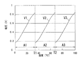
マイコン8は、図3に示すように、予め決められた温度領域(図3では0〜100℃)を3つの測定領域A1,A2,A3に分割している。3つの測定領域A1,A2,A3は、各測定領域A1,A2,A3の両端温度における測温抵抗体1の抵抗値が等比級数的(対数的に等しいもの)になるように分割されている。つまり、温度が0℃、T1、T2、100℃であるときの測温抵抗体1の抵抗値が等比級数的になる(図3のa1,a2,a3参照)。上記マイコン8は、図1に示すように、ADコンバータ7と接続し、両端電圧Vaのアナログ値から変換されたデジタル値をADコンバータ7から入力し、上記入力されたデジタル値に基づいて、測定温度を算出するか、又は、各定抵抗20,21,22の切り替えを行って測定領域A1,A2,A3(図3参照)を切り替えて両端電圧Vaを再入力するかの判断を行う制御手段である。
As shown in FIG. 3, the
次に、基本形態の温度計測装置の動作について説明する。先ず、初期設定について説明する。マイコン8により、複数のスイッチ4を切り替え、定抵抗21をオンにし定抵抗20,22をオフにする。ADコンバータ7により、リファレンス電圧をリファレンス電圧入力ポート72に入力し、標準電圧を入力ポート70に入力する。上記標準電圧をアナログ値からデジタル値に変換し、変換されたデジタル値に基づいて内部抵抗73を推定する。上記推定された内部抵抗73に基づいて真のリファレンス電圧を算出する。続いて、初期設定を行った後について説明する。定抵抗21の両端電圧Vaを入力ポート70に入力する。上記両端電圧Vaに対して、リファレンス電圧を等分割又は等倍して比較を行う。上記比較結果に基づいて、両端電圧Vaをアナログ値からデジタル値に変換し、マイコン8に出力する。次に、マイコン8により、デジタル値に変換された両端電圧Vaを測定領域の最小電圧及び最大電圧(図4参照)と比較する。両端電圧Vaが最小電圧以上であり最大電圧以下である場合、上記両端電圧Vaに基づいて測定温度を算出する。一方、両端電圧Vaが最小電圧より小さい場合、複数のスイッチ4を切り替え、現状より抵抗値の大きい定抵抗20に切り替えて測定領域を低温側にし、ADコンバータ7により、両端電圧Vaを再入力する。両端電圧Vaが最大電圧より大きい場合、複数のスイッチ4を切り替え、現状より抵抗値の小さい定抵抗22に切り替えて測定領域を高温側にし、ADコンバータ7により、両端電圧Vaを再入力する。上記ステップを繰り返すことにより、継続して測定温度を算出することができる。
Next, the operation of the basic form temperature measuring apparatus will be described. First, the initial setting will be described. The
以上、基本形態によれば、各測定領域A1,A2,A3において対応する定抵抗20,21,22の両端電圧Vaの温度変化に対する変化率を大きくすることができるので、略全ての温度領域において測定分解能を効率よく上げることができる。また、複数の定抵抗20,21,22の抵抗値rA1,rA2,rA3が等比級数的に設定されるので、測定分解能をさらに上げることができる。さらに、各測定領域A1,A2,A3において両端電圧Vaの大きさの範囲を略同一にすることができるので、測定分解能をさらに上げることができるとともに、各測定領域A1,A2,A3内の高温領域と低温領域との測定分解能を等しくすることができる。
As described above, according to the basic form , the rate of change with respect to the temperature change of the voltage Va across the corresponding
なお、基本形態の変形例として、測温抵抗体を、例えばPTC(Positive Temperature Coefficient)であり、測定対象の温度が線形的に高くなるにつれて抵抗値が略指数関数的に減少する特性を有するものであってもよい。このような構成にしても、基本形態と同様の効果を得ることができる。 As a modification of the basic form , the resistance temperature detector is a PTC (Positive Temperature Coefficient), for example, and has a characteristic that the resistance value decreases approximately exponentially as the temperature of the measurement target increases linearly. It may be. Even if it is such a structure, the effect similar to a basic form can be acquired.
また、基本形態の他の変形例として、定抵抗の両端電圧をADコンバータに入力することに代わって、測温抵抗体の両端電圧をADコンバータに入力してもよい。このような構成にしても、基本形態と同様の効果を得ることができる。 Further, as another modification of the basic form , instead of inputting the voltage across the constant resistance to the AD converter, the voltage across the resistance temperature detector may be inputted into the AD converter. Even if it is such a structure, the effect similar to a basic form can be acquired.
他の基本形態の温度計測装置は、基本形態の温度計測装置(図1参照)と同様に、測温抵抗体1と、複数の定抵抗2とを備えているが、基本形態の温度計測装置にはない以下に記載の特徴部分がある。
The temperature measuring device of the other basic form, similar to the temperature measuring device of the basic embodiment (see FIG. 1), and the
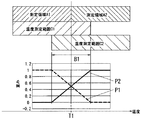
他の基本形態の制御部3(図1参照)において、マイコン8は、図5に示すように、隣接する2つの測定領域(図5のA1,A2参照)の温度測定範囲(図5の温度測定範囲C1、温度測定範囲C2参照)を広げ、上記測定領域のうち予め決められた重複範囲である境界領域(図5のB1参照)を設けている。なお、マイコン8は、隣接する2つの測定領域A2,A3(図4参照)にも同様に、上記測定領域A2,A3のうち予め決められた重複範囲である境界領域を設定している。例えば、測定領域A1と測定領域A2との間に設けられている境界領域B1におけるマイコン8の動作について説明する。先ず、測定領域A2に対応する定抵抗21の両端電圧を入力し、上記両端電圧に基づいて定抵抗21による仮測定温度Ta2を算出する。続いて、測定領域A1に対応する定抵抗20の両端電圧を入力し、上記両端電圧に基づいて定抵抗20による仮測定温度Ta1を算出する。次に、定抵抗21による仮測定温度Ta2に対し、測定領域A1側に近づくにつれて小さくなるように設定された重みP2をつける。上記重みP2は、温度測定範囲C2で測定領域A2を越える部分について境界温度T1から離れるにつれて軽くし、温度測定範囲C2で測定領域A2を越えない部分について境界温度T1から離れるにつれて重くする。つまり、連続的に重みを変化させている。一方、定抵抗20による仮測定温度Ta1に対し、測定領域A2側に近づくにつれて小さくなるように設定された重みP1をつける。上記重みP1は、温度測定範囲C1で測定領域A1を越える部分について境界温度T1から離れるにつれて軽くし、温度測定範囲C1で測定領域A1を越えない部分について境界温度T1から離れるにつれて重くする。つまり、連続的に重みを変化させている。重みをつけられた定抵抗20による仮測定温度Ta1と定抵抗21による仮測定温度Ta2との平均値を測定温度Taとする。なお、他の基本形態の制御部3は、上記以外の点において、基本形態の制御部3と同様である。
In the control unit 3 (see FIG. 1) of another basic form , the
これにより、測定領域の境界点では、各定抵抗が許容範囲内の誤差であったとしても温度変化に不連続な点が出てくることを防止し、境界点を滑らかに接続することができるので、ユーザは境界を意識することなく、この温度計測装置を使用することができる。また、不感帯や不連続な点が発生することがないので、測定領域の境界での温度精度を悪化させることはない。 As a result, even if each constant resistance is an error within the allowable range at the boundary point of the measurement region, it is possible to prevent discontinuous points from appearing in the temperature change, and to smoothly connect the boundary points. Therefore, the user can use this temperature measuring device without being aware of the boundary. Further, since no dead zone or discontinuous points are generated, the temperature accuracy at the boundary of the measurement region is not deteriorated.
以上、他の基本形態によれば、基本形態と同様の効果を得ることができるとともに、測定領域を越えて温度を計測する場合に、ユーザが測定領域の境界を意識することなく測定温度を算出することができる。また、不感帯が存在しないので、境界領域付近でも高精度に測定温度を測定することができる。 As described above, according to the other basic forms , the same effect as the basic form can be obtained, and when the temperature is measured beyond the measurement area, the measurement temperature is calculated without the user being aware of the boundary of the measurement area. can do. Moreover, since there is no dead zone, the measurement temperature can be measured with high accuracy even in the vicinity of the boundary region.
(実施形態1)
実施形態1の温度計測装置は、基本形態の温度計測装置(図1参照)と同様に、測温抵抗体1と、複数の定抵抗2とを備えているが、基本形態の温度計測装置にはない以下に記載の特徴部分がある。
(Embodiment 1 )
Temperature measuring apparatus according to the first embodiment, similar to the temperature measuring device of the basic embodiment (see FIG. 1), and the
本実施形態の温度計測装置は、複数(本実施形態では2つ)の補助抵抗(図示せず)を備えている。各補助抵抗は、定抵抗20,21,22(図1参照)と並列になるように、一端側で測温抵抗体1(図1参照)と直列に接続し、他端側で補助スイッチ(図示せず)と直列に接続する。上記各補助抵抗は、マイコン8(図1参照)により設定される補助測定領域に対応し、両端電圧Vaを測定値としてADコンバータ7(図1参照)に出力する。また、各補助抵抗の抵抗値rB1,rB2は、補助する対象の隣接する測定領域A1,A2,A3に対応する2つの定抵抗20,21,22の抵抗値rA1,rA2,rA3の積の略平方根値であり、rB1=(171.2×5.15)1/2=29.8(kΩ)、rB2=(5.15×0.154)1/2=0.88(kΩ)となる。
The temperature measurement device according to the present embodiment includes a plurality (two in the present embodiment ) of auxiliary resistors (not shown). Each auxiliary resistor is connected in series with the resistance temperature detector 1 (see FIG. 1) on one end side in parallel with the
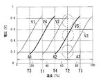
また、本実施形態の制御部3(図1参照)において、マイコン8は、図6に示すように、隣接する測定領域A1,A2,A3のうち予め決められた範囲の補助測定領域(図6のT3−T4間、T4−T5間参照)において、隣接する測定領域A1,A2,A3に対応する2つの定抵抗20,21,22の両端電圧V1,V2,V3に基づく定抵抗による仮測定温度Tb1と、補助抵抗(図示せず)の両端電圧V4,V5に基づく補助抵抗による仮測定温度Tb2との平均値を測定温度Tbとする。なお、本実施形態の制御部3は、上記以外の点において、基本形態の制御部3と同様である。
Further, in the control unit 3 (see FIG. 1) of the present embodiment , as shown in FIG. 6, the
以上、本実施形態によれば、基本形態と同様の効果を得ることができるとともに、補助測定領域(図6のT3−T4間、T4−T5間)の最も測定分解能の高い部分(図6のT1,T2の部分)を、測定領域A1,A2,A3の最も測定分解能が低い部分である境界近傍に設定することができ、測定領域A1,A2,A3と補助測定領域(T3−T4間、T4−T5間)とで二重に温度を測定し、それらの平均を取ることができるので、測定分解能を上げることができる。また、白色性の読み取り誤差が発生した場合であっても、定抵抗20,21,22の両端電圧V1,V2,V3に基づく定抵抗による仮測定温度Tb1と、補助抵抗の両端電圧V4,V5に基づく補助抵抗による仮測定温度Tb2との平均値により、上記誤差要因を低減することができる。
As described above, according to the present embodiment , the same effect as that of the basic embodiment can be obtained, and the auxiliary measurement region (between T3 and T4 in FIG. 6, between T4 and T5) has the highest measurement resolution (in FIG. 6). T1, T2 portion) can be set in the vicinity of the boundary where the measurement resolution of the measurement areas A1, A2, A3 is the lowest, and between the measurement areas A1, A2, A3 and the auxiliary measurement areas (between T3-T4, The temperature can be measured twice between T4 and T5, and the average of them can be taken, so that the measurement resolution can be increased. Even when a white reading error occurs, the provisional measurement temperature Tb1 by the constant resistance based on the voltages V1, V2, and V3 across the
(実施形態2)
実施形態2の温度計測装置は、実施形態1の温度計測装置と同様に、測温抵抗体1(図1参照)と、複数の定抵抗2(図1参照)と、複数の補助抵抗(図示せず)とを備えているが、実施形態1の温度計測装置にはない以下に記載の特徴部分がある。
(Embodiment 2 )
Similar to the temperature measurement device of the first embodiment, the temperature measurement device of the second embodiment includes a resistance temperature detector 1 (see FIG. 1), a plurality of constant resistors 2 (see FIG. 1), and a plurality of auxiliary resistors (see FIG. 1). However, the temperature measuring device of the first embodiment has the following characteristic part.
本実施形態の制御部3(図1参照)において、マイコン8(図1参照)は、単純な相加平均ではなく、測定領域と補助測定領域の線形度に応じて、定抵抗による仮測定温度と補助抵抗による仮測定温度とに重みをつけて平均を取り、平均値を測定温度としている。なお、本実施形態の制御部3は、上記以外の点において、実施形態1の制御部3と同様である。
In the control unit 3 (see FIG. 1) of the present embodiment , the microcomputer 8 (see FIG. 1) is not a simple arithmetic average, but a temporary measurement temperature by a constant resistance according to the linearity of the measurement region and the auxiliary measurement region. And the temporary measured temperature by the auxiliary resistor are weighted and averaged, and the average value is used as the measured temperature. In addition, the
以上、本実施形態によれば、実施形態1と同様の効果をさらに上昇して得ることができる。
As described above, according to this embodiment , the same effect as that of
(実施形態3)
実施形態3の温度計測装置は、実施形態1の温度計測装置と同様に、測温抵抗体1(図1参照)と、複数の定抵抗2(図1参照)と、複数の補助抵抗(図示せず)とを備えているが、実施形態1の温度計測装置にはない以下に記載の特徴部分がある。
(Embodiment 3 )
Similar to the temperature measurement device of the first embodiment, the temperature measurement device of the third embodiment includes a resistance temperature detector 1 (see FIG. 1), a plurality of constant resistors 2 (see FIG. 1), and a plurality of auxiliary resistors (see FIG. 1). However, the temperature measuring device of the first embodiment has the following characteristic part.
本実施形態の制御部3(図1参照)において、マイコン8(図1参照)は、隣接する2つの補助測定領域(図6のT3−T4間、T4−T5間)の温度測定範囲を広げ、上記補助測定領域(T3−T4間、T4−T5間)うち予め決められた重複範囲の補助境界領域を設けている。上記補助境界領域において、それぞれの補助測定領域(T3−T4間、T4−T5間)に対応する補助抵抗(図示せず)の両端電圧V4,V5(図6参照)を入力し、上記両端電圧V4,V5に基づいて補助抵抗による仮測定温度Tc1,Tc2を算出する。次に、入力された2つの補助抵抗による仮測定温度Tc1,Tc2に対し、それぞれ他の補助測定領域側に近づくにつれて小さくなるように設定された重みをつける。重みをつけられた2つの補助抵抗による仮測定温度Tc1,Tc2の平均値と、定抵抗20,21,22の両端電圧V1,V2,V3(図6参照)に基づく定抵抗による仮測定温度Tc3との平均値を測定温度Tcとする。なお、本実施形態の制御部3は、上記以外の点において、実施形態1の制御部3と同様である。
In the control unit 3 (see FIG. 1) of the present embodiment , the microcomputer 8 (see FIG. 1) expands the temperature measurement range in two adjacent auxiliary measurement areas (between T3-T4 and T4-T5 in FIG. 6). In the auxiliary measurement area (between T3 and T4, between T4 and T5), an auxiliary boundary area having a predetermined overlapping range is provided. In the auxiliary boundary region, voltages V4 and V5 (see FIG. 6) of auxiliary resistors (not shown) corresponding to the respective auxiliary measurement regions (between T3 and T4, between T4 and T5) are input, and the both end voltages are input. Based on V4 and V5, provisional measurement temperatures Tc1 and Tc2 by the auxiliary resistance are calculated. Next, a weight set so as to become smaller as it approaches the other auxiliary measurement region side is given to the temporary measurement temperatures Tc1 and Tc2 by the two input auxiliary resistors. Temporary measurement temperature Tc3 by the constant resistance based on the average value of the temporary measurement temperatures Tc1 and Tc2 by the two weighted auxiliary resistors and the voltages V1, V2 and V3 across the
以上、本実施形態によれば、補助測定領域(図6のT3−T4間、T4−T5間)の境界温度を越えて温度を計測する場合に、温度変化に対して測定値を滑らかに変化させることができるので、ユーザが補助測定領域(T3−T4間、T4−T5間)の境界を意識することなく測定温度Tcを算出することができる。また、不感帯が存在しないので、補助境界領域付近でも高精度に測定温度Tcを測定することができる。さらに、測定領域A1,A2,A3と補助測定領域(T3−T4間、T4−T5間)とが重複する範囲を広げることができるので、実施形態1と同様の効果をさらに上昇して得ることができる。 As described above, according to the present embodiment , when the temperature is measured beyond the boundary temperature of the auxiliary measurement region (between T3 and T4 in FIG. 6, between T4 and T5), the measurement value changes smoothly with respect to the temperature change. Therefore, the measurement temperature Tc can be calculated without the user being aware of the boundary of the auxiliary measurement region (between T3 and T4, between T4 and T5). In addition, since there is no dead zone, the measurement temperature Tc can be measured with high accuracy even in the vicinity of the auxiliary boundary region. Furthermore, since the range in which the measurement areas A1, A2, A3 and the auxiliary measurement areas (between T3-T4 and T4-T5) overlap can be expanded, the same effect as in the first embodiment can be further increased. Can do.
(参考例1)
参考例1では、基本形態の温度計測装置において、定抵抗20の抵抗値rA1を変えて温度に対する両端電圧の変化率を測定したものである。
( Reference Example 1 )
In Reference Example 1 , the change rate of the voltage at both ends with respect to the temperature is measured by changing the resistance value rA1 of the
先ず、抵抗値rA1を、測定領域A1において測温抵抗体1の最小値と略同じ抵抗値の29.9kΩとすると、測定領域A1において低分解能領域における両端電圧Vaの変化率は約3.1mV/℃となる。なお、抵抗値rA1を、測温抵抗体1の最大値と同じ抵抗値の1000kΩとする場合も同様の結果となる。また好ましくは、抵抗値rA1を、測定領域A1の中間温度における測温抵抗体1の抵抗値を2倍にした抵抗値と略同じ抵抗値の345kΩとすると、上記変化率は約8.1mV/℃となる。なお、抵抗値rA1を、測定領域A1の中間温度における測温抵抗体1の抵抗値を1/2倍にした抵抗値と略同じ抵抗値の86.5kΩとする場合も同様の結果となる。さらに好ましくは、抵抗値rA1を、測定領域A1の中間温度における測温抵抗体1の抵抗値と略同じ抵抗値の173kΩとすると、上記変化率は約13.7mV/℃となる。
First, if the resistance value rA1 is 29.9 kΩ, which is substantially the same as the minimum value of the
以上、本参考例によれば、定抵抗の抵抗値を、対応する測定領域における測温抵抗体の最小値と最大値との間の大きさにすると、測定領域において低分解能領域における両端電圧の変化率を大きくすることができる。特に、測定領域の中間温度における測温抵抗体1の抵抗値を1/2倍にした値以上、上記測温抵抗体1の抵抗値を2倍にした値以下の抵抗値とすると、両端電圧の変化率が3.5mV/℃を超えるので、両端電圧の範囲(0〜1V)に対して精度よく測定することができる変化率を得ることができる。さらに、測定領域の中間温度における測温抵抗体1の抵抗値と略同じ抵抗値とすると、変化率を飛躍的に大きくすることができる。
As described above, according to this reference example, when the resistance value of the constant resistance is set to a value between the minimum value and the maximum value of the resistance temperature detector in the corresponding measurement region, The rate of change can be increased. In particular, when the resistance value of the
なお、本参考例の変形例として、定抵抗21,22の抵抗値rA2,rA3に対しても、それぞれ測定領域A2,A3において、上記定抵抗20の抵抗値rA1と同様の方法で設定することができる。このようにすると、測定領域A2,A3において、本参考例と同様の効果を得ることができる。
As a modification of this reference example , the resistance values rA2 and rA3 of the
(参考例2)
参考例2の温度計測装置は、基本形態の温度計測装置(図1参照)と同様に、測温抵抗体1を備えているが、基本形態の温度計測装置にはない以下に記載の特徴部分がある。
( Reference Example 2 )
The temperature measuring device of the reference example 2 includes the
本参考例の複数の定抵抗(図1参照)は、2つの定抵抗を備えている。各定抵抗は、マイコン8により設定される測定領域に対応している。なお、本参考例の複数の定抵抗2は、上記以外の点において、基本形態の複数の定抵抗2と同様である。
The plurality of constant resistances (see FIG. 1) of this reference example have two constant resistances. Each constant resistance corresponds to a measurement region set by the
本参考例の温度計測装置において、マイコン8は、予め決められた温度領域を2つの測定領域に分割している。2つの測定領域は、各測定領域の両端温度における測温抵抗体の抵抗値が等比級数的になるように分割されている。つまり、0,50,100℃であるときの測温抵抗体の抵抗値が等比級数的になる。なお、本参考例のマイコン8は、上記以外の点において、基本形態のマイコン8と同様である。
In the temperature measurement device of this reference example , the
次に、本参考例の温度計測装置の低温側の測定領域において、定抵抗の抵抗値を変えた場合の低分解能領域における温度に対する両端電圧の変化率について説明する。先ず、上記定抵抗の抵抗値を、測定領域の中間温度における測温抵抗体の抵抗値を2倍にした抵抗値と略同じ抵抗値の143kΩとすると、上記変化率は約3.7mV/℃となる。なお、上記定抵抗の抵抗値を、測定領域の中間温度における測温抵抗体の抵抗値を1/2倍にした抵抗値と略同じ抵抗値の36kΩとする場合も同様の結果となる。また好ましくは、上記定抵抗の抵抗値を、測定領域の中間温度における測温抵抗体の抵抗値と略同じ抵抗値の71.8kΩとすると、上記変化率は約6.9mV/℃となる。 Next, the change rate of the both-ends voltage with respect to the temperature in the low resolution region when the resistance value of the constant resistance is changed in the low temperature side measurement region of the temperature measuring device of this reference example will be described. First, assuming that the resistance value of the constant resistance is 143 kΩ, which is substantially the same resistance value as the resistance value of the resistance temperature detector doubled at the intermediate temperature in the measurement region, the rate of change is about 3.7 mV / ° C. It becomes. The same result is obtained when the resistance value of the constant resistance is set to 36 kΩ, which is substantially the same as the resistance value obtained by halving the resistance value of the resistance temperature detector at the intermediate temperature in the measurement region. Preferably, if the resistance value of the constant resistance is 71.8 kΩ, which is substantially the same as the resistance value of the resistance temperature detector at the intermediate temperature of the measurement region, the rate of change is about 6.9 mV / ° C.
以上、本参考例によれば、予め決められた温度領域を2つの測定領域に分割した場合であっても、測定領域の中間温度における測温抵抗体1の抵抗値を1/2倍にした値以上、上記測温抵抗体1の抵抗値を2倍にした値以下の抵抗値とすると、低分解能領域における両端電圧の変化率を3.5mV/℃以上にすることができるので、両端電圧の範囲(0〜1V)に対して精度よく測定することができる変化率を得ることができる。さらに、測定領域の中間温度における測温抵抗体の抵抗値と略同じ抵抗値とすると、上記変化率を飛躍的に大きくすることができる。
As described above, according to this reference example , even when the predetermined temperature region is divided into two measurement regions, the resistance value of the
なお、本参考例の変形例として、高温側の測定領域に対応する定抵抗においても、低温側の測定領域に対応する定抵抗と同様の方法で抵抗値を設定することができる。このようにすると、高温側の測定領域において、本参考例と同様の効果を得ることができる。 As a modification of the present reference example , even in a constant resistance corresponding to the high temperature side measurement region, the resistance value can be set by the same method as the constant resistance corresponding to the low temperature side measurement region. If it does in this way, the effect similar to this reference example can be acquired in the measurement area | region of a high temperature side.
1 測温抵抗体
2 複数の定抵抗
4 複数のスイッチ
7 ADコンバータ
8 マイクロコンピュータ
1
Claims (7)
両端温度における前記測温抵抗体の抵抗値が等比級数的になるように、予め決められた温度領域を複数の測定領域に分割し、測定値を入力し、前記測定値に基づいて、測定温度を算出するか、又は前記測定領域を切り替えて前記測定値を再入力するかの判断を行う制御手段と、
それぞれ異なる前記測定領域と対応し、対応する測定領域における前記測温抵抗体の最小値と最大値との間の大きさの抵抗値を有する複数の定抵抗と、
隣接する測定領域に対応する2つの定抵抗の抵抗値の積の略平方根値を抵抗値とする補助抵抗とを備え、
前記制御手段は、前記複数の定抵抗と前記補助抵抗とを選択的に前記測温抵抗体と直列に接続させる機能を有し、前記隣接する測定領域のうち予め決められた範囲の補助測定領域において、前記隣接する測定領域に対応する2つの定抵抗の両端電圧を前記測定値として入力し当該測定値に基づいて前記定抵抗による仮測定温度を算出し、前記補助抵抗の両端電圧を前記測定値として入力し当該測定値に基づいて前記補助抵抗による仮測定温度を算出し、前記定抵抗による仮測定温度と前記補助抵抗による仮測定温度との平均値を前記測定温度とする
ことを特徴とする温度計測装置。 A resistance temperature detector whose resistance value changes approximately exponentially when the temperature changes linearly,
A predetermined temperature region is divided into a plurality of measurement regions so that the resistance value of the resistance temperature detector at both end temperatures becomes a geometric series, and the measurement value is input and measured based on the measurement value. A control means for determining whether to calculate temperature or switch the measurement region and re-input the measurement value ;
A plurality of constant resistances corresponding to the different measurement areas, each having a resistance value having a magnitude between a minimum value and a maximum value of the resistance thermometer in the corresponding measurement area ;
An auxiliary resistor having a resistance value that is approximately the square root of the product of the resistance values of two constant resistances corresponding to adjacent measurement regions ;
The control means has a function of selectively connecting the plurality of constant resistances and the auxiliary resistors in series with the resistance temperature detector, and an auxiliary measurement region in a predetermined range among the adjacent measurement regions The voltage across the two constant resistances corresponding to the adjacent measurement regions is input as the measurement value, the temporary measurement temperature by the constant resistance is calculated based on the measurement value, and the voltage across the auxiliary resistance is measured A temporary measurement temperature by the auxiliary resistance is calculated based on the measured value and the average value of the temporary measurement temperature by the constant resistance and the temporary measurement temperature by the auxiliary resistance is used as the measurement temperature. Temperature measuring device.
前記複数の定抵抗の抵抗値が、等比級数的になることを特徴とする請求項1記載の温度計測装置。 The control means divides the predetermined temperature region into three or more measurement regions;
The temperature measuring apparatus according to claim 1, wherein the resistance values of the plurality of constant resistances are geometric series.
前記制御手段が、前記隣接する測定領域のうち予め決められた範囲の補助測定領域の全てにおいて、前記判断を行う
ことを特徴とする請求項1記載の温度計測装置。 The auxiliary resistance is provided in all adjacent measurement areas,
Said control means, said all of the auxiliary measurement region of a predetermined range of the adjacent measurement regions, a temperature measuring device according to claim 1, characterized in that to perform said determination.
Priority Applications (1)
| Application Number | Priority Date | Filing Date | Title |
|---|---|---|---|
| JP2005061363A JP4613643B2 (en) | 2005-03-04 | 2005-03-04 | Temperature measuring device |
Applications Claiming Priority (1)
| Application Number | Priority Date | Filing Date | Title |
|---|---|---|---|
| JP2005061363A JP4613643B2 (en) | 2005-03-04 | 2005-03-04 | Temperature measuring device |
Publications (2)
| Publication Number | Publication Date |
|---|---|
| JP2006242865A JP2006242865A (en) | 2006-09-14 |
| JP4613643B2 true JP4613643B2 (en) | 2011-01-19 |
Family
ID=37049422
Family Applications (1)
| Application Number | Title | Priority Date | Filing Date |
|---|---|---|---|
| JP2005061363A Expired - Fee Related JP4613643B2 (en) | 2005-03-04 | 2005-03-04 | Temperature measuring device |
Country Status (1)
| Country | Link |
|---|---|
| JP (1) | JP4613643B2 (en) |
Families Citing this family (5)
| Publication number | Priority date | Publication date | Assignee | Title |
|---|---|---|---|---|
| JP5568379B2 (en) * | 2010-05-27 | 2014-08-06 | ラピスセミコンダクタ株式会社 | Detection device |
| JP5738141B2 (en) * | 2011-09-20 | 2015-06-17 | ルネサスエレクトロニクス株式会社 | Semiconductor device and temperature sensor system |
| JP2015200633A (en) * | 2014-04-04 | 2015-11-12 | 株式会社デンソー | Device for correcting temperature characteristic of thermistor and method for correcting temperature characteristic of thermistor |
| JP5885872B2 (en) * | 2015-04-21 | 2016-03-16 | ルネサスエレクトロニクス株式会社 | Semiconductor device |
| JP6583216B2 (en) * | 2016-11-09 | 2019-10-02 | 株式会社デンソー | Thermistor drive circuit |
Citations (8)
| Publication number | Priority date | Publication date | Assignee | Title |
|---|---|---|---|---|
| JPH05273054A (en) * | 1991-04-23 | 1993-10-22 | Toshiba Corp | Cryogenic thermometer |
| JPH07128153A (en) * | 1993-10-29 | 1995-05-19 | Sanyo Electric Co Ltd | Temperature detection apparatus |
| JPH07151612A (en) * | 1993-11-30 | 1995-06-16 | Nec Corp | Temperature measuring instrument using resistance temperature detector |
| JPH07272155A (en) * | 1994-03-28 | 1995-10-20 | Matsushita Electric Works Ltd | Differential type heat sensor |
| JPH0829463A (en) * | 1994-07-19 | 1996-02-02 | Nippondenso Co Ltd | Resistance value detecting device |
| JPH0843213A (en) * | 1994-07-29 | 1996-02-16 | T & D:Kk | Instrument for measuring temperature, etc. |
| JPH10239171A (en) * | 1997-02-28 | 1998-09-11 | Yazaki Corp | Temperature measuring apparatus |
| JPH11248547A (en) * | 1998-03-02 | 1999-09-17 | T & D:Kk | Measuring device and measuring method therefor |
-
2005
- 2005-03-04 JP JP2005061363A patent/JP4613643B2/en not_active Expired - Fee Related
Patent Citations (8)
| Publication number | Priority date | Publication date | Assignee | Title |
|---|---|---|---|---|
| JPH05273054A (en) * | 1991-04-23 | 1993-10-22 | Toshiba Corp | Cryogenic thermometer |
| JPH07128153A (en) * | 1993-10-29 | 1995-05-19 | Sanyo Electric Co Ltd | Temperature detection apparatus |
| JPH07151612A (en) * | 1993-11-30 | 1995-06-16 | Nec Corp | Temperature measuring instrument using resistance temperature detector |
| JPH07272155A (en) * | 1994-03-28 | 1995-10-20 | Matsushita Electric Works Ltd | Differential type heat sensor |
| JPH0829463A (en) * | 1994-07-19 | 1996-02-02 | Nippondenso Co Ltd | Resistance value detecting device |
| JPH0843213A (en) * | 1994-07-29 | 1996-02-16 | T & D:Kk | Instrument for measuring temperature, etc. |
| JPH10239171A (en) * | 1997-02-28 | 1998-09-11 | Yazaki Corp | Temperature measuring apparatus |
| JPH11248547A (en) * | 1998-03-02 | 1999-09-17 | T & D:Kk | Measuring device and measuring method therefor |
Also Published As
| Publication number | Publication date |
|---|---|
| JP2006242865A (en) | 2006-09-14 |
Similar Documents
| Publication | Publication Date | Title |
|---|---|---|
| JP4613643B2 (en) | Temperature measuring device | |
| JP2010249817A (en) | Circuit and method for temperature detection | |
| EP2924405B1 (en) | Intake air temperature sensor and flow measurement device | |
| US9429605B2 (en) | Techniques for determining a resistance value | |
| CN105784179A (en) | Temperature detection circuit | |
| CN106289559A (en) | For the method using the temperature drift compensation of the temperature measuring equipment of thermocouple | |
| JP2002508062A (en) | Temperature measurement by interleaved two-level current of diode and two-level current source therefor | |
| KR101978516B1 (en) | Semiconductor device | |
| KR101375363B1 (en) | Apparatus for measuring temperature using thermistor | |
| KR20030017531A (en) | Method and circuit for measuring a voltage or a temperature and for generating a voltage with any predeterminable temperature dependence | |
| JPS6277604A (en) | Proportional controller | |
| JP2003106886A (en) | Thermal flowmeter | |
| JP2005274372A (en) | Temperature detector | |
| JP2990569B2 (en) | Differential heat detector | |
| US9755640B2 (en) | Resistive input system with resistor matrix | |
| EP3396392A1 (en) | Apparatus and method for determining a power value of a target | |
| JPH0545231A (en) | Temperature measuring device | |
| JP5235963B2 (en) | Temperature measuring device and air conditioner using this temperature measuring device | |
| US10742206B2 (en) | Switching circuit | |
| JP2005241305A (en) | Phase adjustment circuit of watthour meter | |
| US20230048597A1 (en) | Method for temperature measurement and temperature measuring arrangement | |
| JP2008107162A (en) | Sensor | |
| JPH05281053A (en) | Temperature detecting device | |
| JP3070308B2 (en) | Heat detector | |
| Batra et al. | FPGA implementation of interpolation techniques for thermistor linearization |
Legal Events
| Date | Code | Title | Description |
|---|---|---|---|
| A621 | Written request for application examination |
Free format text: JAPANESE INTERMEDIATE CODE: A621 Effective date: 20070405 |
|
| A977 | Report on retrieval |
Free format text: JAPANESE INTERMEDIATE CODE: A971007 Effective date: 20100517 |
|
| A131 | Notification of reasons for refusal |
Free format text: JAPANESE INTERMEDIATE CODE: A131 Effective date: 20100525 |
|
| A521 | Written amendment |
Free format text: JAPANESE INTERMEDIATE CODE: A523 Effective date: 20100726 |
|
| RD04 | Notification of resignation of power of attorney |
Free format text: JAPANESE INTERMEDIATE CODE: A7424 Effective date: 20100726 |
|
| TRDD | Decision of grant or rejection written | ||
| A01 | Written decision to grant a patent or to grant a registration (utility model) |
Free format text: JAPANESE INTERMEDIATE CODE: A01 Effective date: 20100921 |
|
| A01 | Written decision to grant a patent or to grant a registration (utility model) |
Free format text: JAPANESE INTERMEDIATE CODE: A01 |
|
| A61 | First payment of annual fees (during grant procedure) |
Free format text: JAPANESE INTERMEDIATE CODE: A61 Effective date: 20101004 |
|
| R151 | Written notification of patent or utility model registration |
Ref document number: 4613643 Country of ref document: JP Free format text: JAPANESE INTERMEDIATE CODE: R151 |
|
| FPAY | Renewal fee payment (event date is renewal date of database) |
Free format text: PAYMENT UNTIL: 20131029 Year of fee payment: 3 |
|
| S111 | Request for change of ownership or part of ownership |
Free format text: JAPANESE INTERMEDIATE CODE: R313111 |
|
| R350 | Written notification of registration of transfer |
Free format text: JAPANESE INTERMEDIATE CODE: R350 |
|
| S111 | Request for change of ownership or part of ownership |
Free format text: JAPANESE INTERMEDIATE CODE: R313113 |
|
| R350 | Written notification of registration of transfer |
Free format text: JAPANESE INTERMEDIATE CODE: R350 |
|
| R250 | Receipt of annual fees |
Free format text: JAPANESE INTERMEDIATE CODE: R250 |
|
| R250 | Receipt of annual fees |
Free format text: JAPANESE INTERMEDIATE CODE: R250 |
|
| R250 | Receipt of annual fees |
Free format text: JAPANESE INTERMEDIATE CODE: R250 |
|
| R250 | Receipt of annual fees |
Free format text: JAPANESE INTERMEDIATE CODE: R250 |
|
| R250 | Receipt of annual fees |
Free format text: JAPANESE INTERMEDIATE CODE: R250 |
|
| LAPS | Cancellation because of no payment of annual fees |