JP4612756B2 - Radiography equipment - Google Patents
Radiography equipment Download PDFInfo
- Publication number
- JP4612756B2 JP4612756B2 JP2000051095A JP2000051095A JP4612756B2 JP 4612756 B2 JP4612756 B2 JP 4612756B2 JP 2000051095 A JP2000051095 A JP 2000051095A JP 2000051095 A JP2000051095 A JP 2000051095A JP 4612756 B2 JP4612756 B2 JP 4612756B2
- Authority
- JP
- Japan
- Prior art keywords
- receiver
- top plate
- subject
- horizontal
- image
- Prior art date
- Legal status (The legal status is an assumption and is not a legal conclusion. Google has not performed a legal analysis and makes no representation as to the accuracy of the status listed.)
- Expired - Fee Related
Links
- 238000002601 radiography Methods 0.000 title 1
- 230000007246 mechanism Effects 0.000 claims description 32
- 230000005855 radiation Effects 0.000 claims description 23
- 238000003384 imaging method Methods 0.000 claims description 13
- 230000008859 change Effects 0.000 claims description 7
- 238000001514 detection method Methods 0.000 claims description 5
- OAICVXFJPJFONN-UHFFFAOYSA-N Phosphorus Chemical compound [P] OAICVXFJPJFONN-UHFFFAOYSA-N 0.000 description 10
- 238000010586 diagram Methods 0.000 description 8
- 238000000034 method Methods 0.000 description 6
- 239000000463 material Substances 0.000 description 4
- 238000007689 inspection Methods 0.000 description 2
- 239000004065 semiconductor Substances 0.000 description 2
- 230000035939 shock Effects 0.000 description 2
- OKTJSMMVPCPJKN-UHFFFAOYSA-N Carbon Chemical compound [C] OKTJSMMVPCPJKN-UHFFFAOYSA-N 0.000 description 1
- 125000002066 L-histidyl group Chemical group [H]N1C([H])=NC(C([H])([H])[C@](C(=O)[*])([H])N([H])[H])=C1[H] 0.000 description 1
- VYPSYNLAJGMNEJ-UHFFFAOYSA-N Silicium dioxide Chemical compound O=[Si]=O VYPSYNLAJGMNEJ-UHFFFAOYSA-N 0.000 description 1
- 230000003187 abdominal effect Effects 0.000 description 1
- 239000006096 absorbing agent Substances 0.000 description 1
- NIXOWILDQLNWCW-UHFFFAOYSA-N acrylic acid group Chemical group C(C=C)(=O)O NIXOWILDQLNWCW-UHFFFAOYSA-N 0.000 description 1
- 229910052799 carbon Inorganic materials 0.000 description 1
- 230000008878 coupling Effects 0.000 description 1
- 238000010168 coupling process Methods 0.000 description 1
- 238000005859 coupling reaction Methods 0.000 description 1
- 230000001066 destructive effect Effects 0.000 description 1
- 238000003745 diagnosis Methods 0.000 description 1
- 230000000694 effects Effects 0.000 description 1
- 238000005516 engineering process Methods 0.000 description 1
- 230000005284 excitation Effects 0.000 description 1
- 230000001771 impaired effect Effects 0.000 description 1
- 238000004020 luminiscence type Methods 0.000 description 1
- 239000002184 metal Substances 0.000 description 1
- 230000004048 modification Effects 0.000 description 1
- 238000012986 modification Methods 0.000 description 1
- 230000008569 process Effects 0.000 description 1
- 239000000126 substance Substances 0.000 description 1
- 239000000758 substrate Substances 0.000 description 1
- 239000002023 wood Substances 0.000 description 1
Images


Landscapes
- Radiography Using Non-Light Waves (AREA)
- Apparatus For Radiation Diagnosis (AREA)
Description
【0001】
【発明の属する技術分野】
本発明は、被検者にX線等の放射線を投射して放射線画像を撮影する装置に関するものである。
【0002】
【従来の技術】
放射線撮影装置は、被検者の医療診断などの医療分野、物質の非破壊検査等の検査分野で使用されており、放射線画像を受像する受像器にはいくつかの方式が存在する。
【0003】
第1の方式は、増感紙と放射線写真フィルムを密着させて使用する放射線写真法である。これは被写体を透過した放射線が増感紙に入射すると、増感紙に含まれている蛍光体が放射線のエネルギを吸収して蛍光を発生し、この蛍光により放射線写真フィルムが感光し、放射線像を可視像として記録する。
【0004】
第2の方式は、蓄積性蛍光体から成る放射線検出器を備えた画像記録再生装置として知られている。放射線が被写体を透過して蓄積性蛍光体に入射すると、蓄積性蛍光体は放射線エネルギの一部を蓄積する。そして蓄積性蛍光体に可視光を照射すると、蓄積性蛍光体は蓄積したエネルギに応じた輝尽発光を示す。つまり蓄積性蛍光体は被写体の放射線画像情報を蓄積し、走査手段が蓄積性蛍光体をレーザー光等の励起光により走査し、信号読取手段が輝尽発光光を光電的に読み取り、写真感光材料等の記録材料又はCRT等の表示手段が可視像として記録又は表示する。
【0005】
第3の方式として、放射線をリアルタイムで検出して直接デジタル出力する放射線検出器が知られており、例えば特開平8−116044号公報にその原理が記載されている。デジタル検出器は半導体プロセス技術の進歩により可能となったもので、シンチレータと固体光検出器を積層して、シンチレータは放射線を可視光に変換し、固体光検出器は可視光を光電変換する。固体光検出器は石英ガラスから成る基板上に、透明導電膜と導電膜から成る固体光検出素子をアモルファス半導体膜で挟んでマトリクス状に配列した構成を有する。放射線検出器は数mmの厚さの平面パネル状であるため薄型軽量化が容易である。
【0006】
図6は具体的な装置構成の一例を示すものである。被検者Sの四肢、頭部、腹部等の単純撮影する際に使用するブッキー撮影台を、その長手方向(被験者の頭上方向)から見た図である。この撮影台では天板1上に横たわる被検者Sに対して、上方に位置する管球TからX線を曝射し、被検者Sを透過したX線を受像器2により受像して放射線画像を得る。
【0007】
【発明が解決しようとする課題】
医療の現場では簡便な操作で様々な方向から被験者の画像を得たいという要望があり、これに応えるものとして図7に示すような装置がある。この装置では、天板1上の被検者Sの側面を撮影するために、天板1の下の受像器2を使用する代りに、フィルム又は蓄積性蛍光体シートを収納したカセッテ3を被検者Sの側方に置いて、側方から管球T’でX線を曝射し、被検者Sを透過したX線をカセッテ3のフィルムで受像するものである。
【0008】
しかしできることなら、どの方向から撮影するにしても同一の受像器を用いた撮影が望まれる。またその際に安全性や操作性を損なうことがあってはならない。
【0009】
【課題を解決するための手段】
本発明は上記要望に応えるためになされたもので、本発明の一形態による放射線撮像装置は、被験者を載せ水平方向で移動可能な天板と、前記被験者の放射線画像を受像する受像器と、前記天板に対する前記受像器の水平方向の位置および前記天板に対する前記受像器の姿勢を可変にする移動機構、および前記天板に対して前記受像器の姿勢が水平でない場合に前記天板の所定方向の移動を制限する制限手段を有することを特徴とする。
【0010】
本発明の別の形態の放射線撮像装置は、被験者を載せ水平方向で移動可能な天板と、前記被験者の放射線画像を受像する受像器と、前記天板に対する前記受像器の水平方向の位置、および前記天板に対する前記受像器の姿勢を可変にする移動機構および前記天板の位置に応じて前記受像器の姿勢変更を制限する制限手段を有することを特徴とする。
【0011】
本発明のさらに別の形態の放射線撮影装置は、被験者を載せ水平方向で移動可能な天板と、前記被験者の放射線画像を受像する受像器と、前記天板に対する前記受像器の水平方向の位置、および前記天板に対する前記受像器の姿勢を可変にする移動機構、および前記天板に対して前記受像器の姿勢が水平でない場合に前記天板を前記受像器のある方向に移動させた際、あるいは前記天板が所定の範囲に位置している場合に受像器の姿勢を水平から変更した際に、前記天板と前記受像器との間に位置して両者の直接の衝突を避ける緩衝部材を有することを特徴とする。
【0012】
本発明のさらに別の形態の放射線撮影装置は、被験者を載せ水平方向で移動可能な天板と、前記被験者の放射線画像を受像する受像器と、前記天板に対する前記受像器の水平方向の位置および前記天板に対する前記受像器の姿勢を可変にする移動機構、および前記天板に対して前記受像器の姿勢が水平でなく、且つ前記天板が所定の範囲にある場合に前記天板の所定方向の移動を制限する制限手段を有することを特徴とする。
【0013】
本発明のさらに別の形態の放射線撮影装置は、被験者を載せ水平方向で移動可能な天板と、前記被験者の放射線画像を受像する受像器、および前記天板に対する前記受像器の水平方向の位置、および前記天板に対する前記受像器の姿勢を可変にする移動機構を有し、該移動機構は前記天板に対して前記受像器の姿勢が水平でない場合に該受像器の水平方向の移動を行えなくする機構を備えることを特徴とする。
【0014】
【発明の実施の形態】
本発明の実施形態を図面を参照して詳細に説明する。なお、以下の説明では放射線画像を受像する受像器の例としてデジタル放射線検出器を用いた例を示すが、これに限定されるわけではなく、放射線写真フィルムまたは蓄積性蛍光体シートを入れたカセッテを使用する受像器に置きかえることもできる。
【0015】
図1は放射線撮影装置の全体概要図である。X線発生装置であるX線管球はT、T’のいずれかの位置に選択的に設置可能で、被験者Sに向けて上方または側方からX線を投射する。テーブル・ベッド等の撮影台の天板101は撮影する被検者Sを載せるもので、その材質はアクリル板、カーボン板又は木材である。天板101は支持台110の上に水平面で移動可能に支持されている。天板101の下方で支持台110の上面には、X線デジタル検出器を内蔵した受像器113を配置している。X線デジタル検出器の具体例については特開平8−116044号を参照されたい。撮影技師(オペレータ)が天板101下から受像器113を被験者に対して側方、すなわち水平面内の横方向(以下、これを「第1方向」、また水平面内で第1方向と直交する方向を「第2方向」と定義する)に引き出して露出した状態(図1の状態H)にすること、ならびに天板101内から側方に露出した後に回転させて鉛直状態(図1の状態V)にすることを可能とする移動機構を備えている。この移動機構は受像器113を天板101の水平に沿う方向に案内するガイドレールからなる案内機構114と、天板101の側方に露出した受像器113を水平状態から鉛直状態に回転可能とする回転軸を含む回転連結機構115とを有する。受像器113は、天板101のから引き出して水平状態Hおよび鉛直状態Vのいずれにでも設置できるので、同一の受像器113によって異なる方向から被験者を撮影できる。
【0016】
また、天板101を上下方向に昇降移動させ、床からの高さを変えることのできる昇降機構を撮影台に内蔵している。これにより、被検者が天板に登り降りする際に天板の高さを被検者の負担が少ない位置まで下げたり、ストレッチャからの移乗においては介助者の作業しやすい高さに合わせることを可能としている。また撮影時には、撮影技師が被検者のポジショニング等の作業を行いやすい高さに設定できるので、撮影技師自体の負担も軽減される。
【0017】
さてここで、受像器113を側方に引き出して鉛直に設置した状態(状態V)で被検者を側方から撮影する場合を考える。このとき被検者を載せた天板113を第1方向(図中右方向)に大きく移動させると、天板101の側面と受像器113の受像面とが干渉して衝突する可能性がある。天板113の質量は通常30〜40kg程度ありこれに70Kgの被検者を載せれば100kgを越える。そのため例え移動速度が小さくても衝突した際の衝撃は大きく、最悪、受像器113の破損や故障を生じる。一方、受像器113を水平状態(状態H)から鉛直状態(状態V)に回転させて姿勢変更する際に、受像器113の引出し方が不完全であったとすると(すなわち水平状態の受像器113の一部が天板101の下に残っている場合)、天板101の側面のエッジが受像器113の側面に干渉して衝突し、最悪、受像器113の破損や故障を引き起こす可能性がある。本実施形態の装置ではこれらの課題を解決するための工夫がこらされており、以下、詳細に説明する。
【0018】
図2は図1の装置のより詳細な構成図である。金属製のレール102は天板101を水平方向に移動させるためのもので、レール102の内側には溝が形成されている。可動フレーム103に取付けたリニアベアリング104のコロが回転することにより、天板101は被験者に対して長手の第2方向(図中、手前奥方向)に滑らかに自在に移動する。更に可動フレーム103の下部にはリニアベアリング105が設けられ、支持台110に固着された固定フレーム106に取付けられたシャフト107に沿って、可動フレーム103は被験者に対して側方の第1方向(図中左右方向)に自在に移動することができる。この水平面内で直交する2方向の移動の組み合わせによって、天板101に被検者Sを載せた状態で操作技師が手で天板101を水平面を自在に移動させることが可能となる。一方、可動フレーム103はレール102の第2方向の移動を固定するロック機構108を有し、同様に固定フレーム106は可動フレーム103の第1方向の移動を固定するロック機構109を有している。これらロック機構108、109はそれぞれ電磁石131を備え、磁気によりレール102/可動フレーム103に吸着固定してロックすることで、天板101の自在の移動を禁止することができる。ロックの有無の制御は第1制御器111により行う。通常状態では天板101が第1、第2方向のいずれにも動かないようにロックするが、必要な場合は撮影技師の意思でロック解除を行えるようになっており操作の容易性及び安全性を両立している。このロック解除操作は、図2で示すように支持台110の下部に設けたマイクロスイッチを含むフットスイッチ112を撮影技師が足で操作することで行う。
【0019】
一方、上述したように天板101に対して受像器113を水平移動と回転移動させるための案内機構114および回転連結部材115を設けている。回転連結部材115の近傍には、マイクロスイッチ又はフォトインタラプタからなる姿勢検知器116を備えている。図3は回転連結部材115周辺の斜視図であり、姿勢検知器116の配置を説明するものである。受像器113の回転の支軸となる回転連結部材115はブロック部材121に設けられ、円柱面には突起部115aが形成されている。受像器113が水平状態にある時は突起部115aがマイクロスイッチ117のレバー117aを押し、受像器113が鉛直状態になった時は突起部115aがレバー117aから離れるように、マイクロスイッチ117を配置している。これにより受像器113が水平状態にあるのか鉛直状態にあるのか、すなわち天板に対する受像器の姿勢を検知する。姿勢検知器116からの信号は前述のフットスイッチ112からの信号と共に第1制御器111に入力する。そして姿勢検知器116の検知結果に応じて、フットスイッチ112からの入力操作を制限する。具体的には第1制御器111は、姿勢検知器116が受像器113が鉛直状態にあることを検知した場合、たとえフットスイッチ112が操作されてもロック解除を行わずに天板101の移動を禁止する。逆に姿勢検知器116が受像器113が水平状態にあることを検知した場合は、フットスイッチ112の入力に従いロックを解除し、天板101の移動が行えるように制御する。
【0020】
天板101上に被検者を載せて上方より撮影する場合は、受像器113は天板101の下方で水平状態に位置させる。受像器が水平状態であることは姿勢検知器116で検知され、フットスイッチ112の操作が有効になるので、操作技師がロックを解除すれば天板101の移動が可能となる。一方、被検者を側方から撮影する場合は、受像器113を天板101の側方(第1方向)に一杯に引き出した後、受像器113を水平状態から鉛直状態に姿勢を切り替える。受像器113が鉛直状態であることは姿勢検知器116で検知されるので、第1制御器111の制御により例えフットスイッチ112が押されてもロック解除を行わない。操作技師が天板101を動かそうとしても移動できないので誤って受像器113に衝突することを防止している。なお天板101を第2方向に動かしても受像器113と干渉することは無いので、変形例として天板101の第1方向と第2方向の両方をロック制御する代わりに、第1方向のみロック制御、すなわちロック機構119のみを制御してロック機構118は制御せず、第2方向は受像器113の姿勢とは無関係に移動できるようしても良い。こうすれば受像器113が鉛直状態であっても、撮影技師が天板101を第2方向にだけは動かすことができ、この方向での撮影部位の変更や修正を行える。
【0021】
なお、鉛直状態となっている受像器113が、もし水平方向(第1方向)に動くことが出来るとすると、受像器113が天板101の側面に衝突してしまうことも考えられる。これを防ぐために受像器113の移動機構は、受像器113が鉛直状態では水平方向へ動かせないようなロック構造となっている。これは機械的なロック機構であっても、あるいはセンサと電磁手段(アクチュエータ又はソレノイド)を用いた電磁的なロック機構であってもよい。
【0022】
一方、上述したように、受像器113を水平状態から鉛直状態に回転させて受像器113の姿勢を変更する際に受像器113が天板101の側面に衝突する可能性があるが、本実施形態の装置はこれを未然に防止する機構も有している。図2において、位置検知器118は可動フレーム103の位置を検知する。可動フレーム103と天板101との位置関係は、天板101の移動により第2方向には変化するが第1方向においては変化しないので、結果的に位置検知器118は天板101の第1方向の位置を検知することになる。位置検知器118はマイクロスイッチ119を有し、マイクロスイッチ119から伸びたレバー119aが可動フレーム103の移動を検知する。天板101が鉛直状態の受像器113と干渉しない位置関係にある場合には、可動フレーム103の底面でレバー119aが押されONとなる。一方、天板101が鉛直の受像器113と干渉するような位置関係では、レバー119aが可動フレーム103の底面から外れてスイッチがOFFとなる。こうして位置検知器118は受像器113が鉛直である際の天板101の第1方向への移動の許容範囲を検知する。
【0023】
また、受像器113を回転させて姿勢変更するための回転連結部材115近傍には回転ロック機構120を設けている。これは水平状態から鉛直状態に受像器113の姿勢を切り替える時にこの回転を規制するものであり、図4に示すような構造を持つ。同図において、受像器113に取付けられたブロック部材121は、回転連結部材115を固定するための穴121aを有する。これに対向して、案内機構114にはソレノイド122を配置し、受像器113が水平状態にある時にブロック部材121の穴121aとソレノイド122の直動軸122aが一致する。ソレノイド122は第2制御器123により駆動し、直動軸122aを穴121aに挿入することでブロック部材121の回転をロックし、受像器113の水平状態から鉛直状態への姿勢変更をできなくする。
【0024】
第2制御器123には前記の位置検知器118からの信号も入力しており、位置検知器118の検知に基づいて回転ロック機構120を制御する。位置検知器118がONである時、すなわち図2のように天板101と受像器113とが干渉しない位置に天板101がある場合、回転のロックが解除され、撮影技師は必要に応じて受像器113の姿勢変換を行うことができる。逆に位置検知器118がOFFを検知している時、すなわち天板101と受像器113とが干渉する位置に天板101がある場合は、ソレノイドの駆動によって回転がロックされ、受像器113の姿勢変換は行えず、天板101の側面(レール102)との干渉は起こらない。受像器113を鉛直状態にする際は、天板101を干渉しない位置まで動かして離すことで、ソレノイド122が駆動して姿勢変更が可能となる。
【0025】
なお上記例では、受像器113が鉛直状態にある場合、天板101の少なくとも第1方向への移動を完全にロックするようにしているが、さらに位置検知器118の信号を利用して、天板101を受像器113との干渉が生じる範囲へは入れないようにして、それ以外の範囲では天板101が第1方向、第2方向ともに移動できるようにしてもよい。具体的には位置検知器118の検知がOFFとなったらロック機構109を作動させるロジックで実現される。これにより受像器113が鉛直状態でも天板101の移動可能な範囲が広がり、被検者のポジショニングがより容易となる。
【0026】
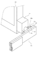
図5は上記例の変形例を示す。上記例では天板に対して受像器の姿勢が水平でない場合に天板の側方方向への移動を制限している、あるいは天板の位置に応じてソレノイドを駆動して受像器の回転を規制して姿勢変更を制限している、これに対して図5の例では、天板の移動や受像器の回転を規制する代わりに、緩衝部材を含む保護手段を設けることで天板101の側面のエッジが直接受像器113の受像面に衝突することを防ぐようにしたものである。
【0027】
具体的な機構を以下説明する。図5に示すように、ブロック部材121に小さな緩衝部材132を固設して、その頭部は受像器131の外枠および受像面よりも突出している。緩衝部材は132は例えば少なくとも頭部をゴムなどの柔軟性を有する材料としたり、ばねを用いたショックアブソーバーによって衝撃を吸収するものである。別の形態としては上記姿勢検知器141の信号をもとにアクチュエータで緩衝部材を突出させるような機構としてもよい。この緩衝部材132は、受像器113の姿勢を鉛直状態に変更した際に、該緩衝部材の頭部が天板101と同じ高さになる位置に設けている。これにより仮に天板101が側方に寄せられら状態で、操作技師が誤って受像器131を水平から鉛直に切り替えても、緩衝部材132の頭部が天板101の側面に当たって衝撃を吸収し、その勢いで天板101を干渉が無い範囲まで押し戻される。一方、受像器113が鉛直状態にあるときに操作技師が誤って天板101を側方に移動させたとしても緩衝材を介しての間接的な衝突となる。このため受像器113への直接の衝撃はなく受像面の損傷や故障を避けることができる。なお緩衝部材132は受像器113側に設けずに天板101側に設けてもよい。すなわち天板101の側面で受像器113の受像面と干渉しない位置に緩衝部材を設けてもよく、要は受像器113の受像面と天板101の側面との直接の衝突が避けられる位置に干渉部材を設ければよい。
【0028】
【発明の効果】
本発明によれば、移動可能な天板とそれに対する位置や姿勢を可変にし得る受像器とを備えた放射線撮影装置において、天板と受像器との干渉による損傷や故障などの不具合を未然に防ぐことができ、信頼性ならびに安全性の高い装置を提供することができる。
【図面の簡単な説明】
【図1】放射線撮影装置の実施例の全体概要図
【図2】図1の装置の詳細構成図
【図3】図1の装置の部分構成図
【図4】図1の装置の部分構成図
【図5】変形例の部分構成図
【図6】従来例の構成図
【図7】従来例の構成図
【符号の説明】
100 天板
102 レール
103 可動フレーム
104 第1リニアベアリング
105 第2リニアベアリング
106 固定フレーム
108、109 ロック機構
110 支持台
111 第1制御器
112 フットスイッチ
113 受像器
114 案内機構
115 回転連結部材
116 姿勢検知器
118 位置検知器
120 回転ロック機構
121 ブロック部材
122 ソレノイド
123 第2制御器
130 移動機構
131 電磁石
132 緩衝部材[0001]
BACKGROUND OF THE INVENTION
The present invention relates to an apparatus for capturing a radiographic image by projecting radiation such as X-rays onto a subject.
[0002]
[Prior art]
The radiographic apparatus is used in the medical field such as medical diagnosis of a subject, and in the inspection field such as non-destructive inspection of a substance, and there are several types of receivers that receive a radiographic image.
[0003]
The first method is a radiographic method in which an intensifying screen and a radiographic film are used in close contact. This is because when the radiation that has passed through the subject enters the intensifying screen, the phosphor contained in the intensifying screen absorbs the energy of the radiation and generates fluorescence. Is recorded as a visible image.
[0004]
The second method is known as an image recording / reproducing apparatus including a radiation detector made of a stimulable phosphor. When radiation passes through the subject and enters the stimulable phosphor, the stimulable phosphor stores a portion of the radiation energy. When the stimulable phosphor is irradiated with visible light, the stimulable phosphor exhibits stimulated emission corresponding to the accumulated energy. That is, the stimulable phosphor accumulates radiographic image information of the subject, the scanning means scans the stimulable phosphor with excitation light such as laser light, and the signal reading means photoelectrically reads the photostimulated luminescence light. A recording material such as CRT or a display means such as a CRT records or displays it as a visible image.
[0005]
As a third method, a radiation detector that detects radiation in real time and directly outputs the radiation is known. For example, Japanese Patent Application Laid-Open No. 8-116044 describes the principle. Digital detectors have become possible due to advances in semiconductor process technology. A scintillator and a solid-state photodetector are stacked, the scintillator converts radiation into visible light, and the solid-state detector photoelectrically converts visible light. The solid-state photodetector has a configuration in which a solid-state photodetector composed of a transparent conductive film and a conductive film is sandwiched between amorphous semiconductor films on a substrate made of quartz glass. Since the radiation detector has a flat panel shape with a thickness of several millimeters, it is easy to reduce the thickness and weight.
[0006]
FIG. 6 shows an example of a specific apparatus configuration. It is the figure which looked at the Bucky imaging stand used when the subject's S limbs, a head, an abdominal part, etc. are imaged simply from the longitudinal direction (subject's overhead direction). In this imaging table, the subject S lying on the top board 1 is exposed to X-rays from the tube T positioned above, and the X-rays transmitted through the subject S are received by the
[0007]
[Problems to be solved by the invention]
In the medical field, there is a demand for obtaining images of a subject from various directions with a simple operation, and there is an apparatus as shown in FIG. In this apparatus, in order to photograph the side surface of the subject S on the top plate 1, instead of using the
[0008]
However, if possible, photographing using the same receiver is desired no matter what direction the photographing is performed. At that time, safety and operability should not be impaired.
[0009]
[Means for Solving the Problems]
The present invention has been made to meet the above-mentioned demand, and a radiation imaging apparatus according to an embodiment of the present invention includes a top plate that can move a subject on a horizontal direction, a receiver that receives the radiation image of the subject, A moving mechanism that varies a horizontal position of the receiver with respect to the top plate and a posture of the receiver with respect to the top plate; and a position of the top plate when the posture of the receiver is not horizontal with respect to the top plate. It has a restricting means for restricting movement in a predetermined direction.
[0010]
A radiation imaging apparatus according to another aspect of the present invention includes a top plate that can move a subject in a horizontal direction, a receiver that receives a radiation image of the subject, and a horizontal position of the receiver with respect to the top plate, And a moving mechanism that makes the posture of the receiver relative to the top plate variable, and a limiting unit that restricts a change in the posture of the receiver according to the position of the top plate.
[0011]
According to still another aspect of the present invention, there is provided a radiographic apparatus, a top plate on which a subject can be placed and moved in a horizontal direction, a receiver that receives a radiographic image of the subject, and a horizontal position of the receiver with respect to the top plate And a moving mechanism that makes the posture of the receiver relative to the top plate, and when the top plate is moved in a certain direction of the receiver when the posture of the receiver is not horizontal with respect to the top plate. Or a buffer located between the top plate and the receiver to avoid a direct collision between the top plate and the receiver when the orientation of the receiver is changed from horizontal when the top plate is located within a predetermined range. It has the member.
[0012]
According to still another aspect of the present invention, there is provided a radiographic apparatus, a top plate on which a subject can be placed and moved in a horizontal direction, a receiver that receives a radiographic image of the subject, and a horizontal position of the receiver with respect to the top plate And a moving mechanism that makes the posture of the receiver relative to the top plate, and a posture of the receiver that is not horizontal with respect to the top plate and the top plate is within a predetermined range. It has a restricting means for restricting movement in a predetermined direction.
[0013]
According to still another aspect of the present invention, there is provided a radiographic apparatus, a top plate on which a subject can be placed and moved in a horizontal direction, a receiver for receiving a radiographic image of the subject, and a horizontal position of the receiver with respect to the top plate And a moving mechanism that makes the posture of the receiver relative to the top plate variable, and the moving mechanism moves the receiver in the horizontal direction when the posture of the receiver is not horizontal with respect to the top plate. It is characterized by having a mechanism that disables it.
[0014]
DETAILED DESCRIPTION OF THE INVENTION
Embodiments of the present invention will be described in detail with reference to the drawings. In the following description, an example in which a digital radiation detector is used as an example of a receiver for receiving a radiation image is shown. However, the present invention is not limited to this, and a cassette including a radiographic film or a storage phosphor sheet is used. It can also be replaced with a receiver that uses.
[0015]
FIG. 1 is an overall schematic diagram of the radiation imaging apparatus. An X-ray tube, which is an X-ray generator, can be selectively installed at any position of T and T ′, and projects X-rays toward the subject S from above or from the side. A
[0016]
In addition, a lifting mechanism that can move the
[0017]
Now, consider a case where the subject is photographed from the side in a state where the
[0018]
FIG. 2 is a more detailed block diagram of the apparatus of FIG. The
[0019]
On the other hand, as described above, the
[0020]
When the subject is placed on the
[0021]
If the
[0022]
On the other hand, as described above, when the
[0023]
A
[0024]
A signal from the
[0025]
In the above example, when the
[0026]
FIG. 5 shows a modification of the above example. In the above example, when the orientation of the receiver is not horizontal with respect to the top plate, the movement of the top plate in the lateral direction is restricted, or the solenoid is driven according to the position of the top plate to rotate the receiver. In contrast to this, in the example of FIG. 5, instead of restricting the movement of the top plate and the rotation of the receiver, by providing a protection means including a buffer member, the
[0027]
A specific mechanism will be described below. As shown in FIG. 5, a
[0028]
【The invention's effect】
According to the present invention, in a radiation imaging apparatus including a movable top plate and a receiver that can change the position and orientation of the movable top plate, problems such as damage and failure due to interference between the top plate and the receiver are obviated. Therefore, it is possible to provide a highly reliable and safe device.
[Brief description of the drawings]
FIG. 1 is an overall schematic diagram of an embodiment of a radiation imaging apparatus. FIG. 2 is a detailed configuration diagram of the apparatus in FIG. 1. FIG. 3 is a partial configuration diagram of the apparatus in FIG. FIG. 5 is a partial configuration diagram of a modified example. FIG. 6 is a configuration diagram of a conventional example. FIG. 7 is a configuration diagram of a conventional example.
100
Claims (3)
前記天板に対する姿勢が可変であって、前記被検者の放射線画像を受像する受像器と、
前記受像器を前記被検者に対して側方方向に水平移動可能にすると共に、前記受像器の姿勢を水平と鉛直のいずれかにすることを可能にする移動機構と、
前記受像器の姿勢を検知する検知器と、
前記天板に対して前記受像器の姿勢が水平でない場合に、前記検知器の検知に基づいて前記天板の移動を制限する制限手段と、
を有することを特徴とする放射線撮影装置。A horizontal plate that can be moved horizontally, and a top plate for placing the subject;
A receiver that is variable in posture with respect to the top plate and receives a radiographic image of the subject;
A moving mechanism that enables the receiver to move horizontally in the lateral direction with respect to the subject, and allows the posture of the receiver to be either horizontal or vertical;
A detector for detecting the attitude of the receiver;
Limiting means for limiting the movement of the top plate based on the detection of the detector when the orientation of the receiver is not horizontal with respect to the top plate;
A radiation imaging apparatus comprising:
Priority Applications (2)
| Application Number | Priority Date | Filing Date | Title |
|---|---|---|---|
| JP2000051095A JP4612756B2 (en) | 2000-02-28 | 2000-02-28 | Radiography equipment |
| US09/770,667 US6928145B2 (en) | 2000-02-01 | 2001-01-29 | Radiographic apparatus |
Applications Claiming Priority (1)
| Application Number | Priority Date | Filing Date | Title |
|---|---|---|---|
| JP2000051095A JP4612756B2 (en) | 2000-02-28 | 2000-02-28 | Radiography equipment |
Publications (3)
| Publication Number | Publication Date |
|---|---|
| JP2001238880A JP2001238880A (en) | 2001-09-04 |
| JP2001238880A5 JP2001238880A5 (en) | 2007-04-12 |
| JP4612756B2 true JP4612756B2 (en) | 2011-01-12 |
Family
ID=18572792
Family Applications (1)
| Application Number | Title | Priority Date | Filing Date |
|---|---|---|---|
| JP2000051095A Expired - Fee Related JP4612756B2 (en) | 2000-02-01 | 2000-02-28 | Radiography equipment |
Country Status (1)
| Country | Link |
|---|---|
| JP (1) | JP4612756B2 (en) |
Families Citing this family (1)
| Publication number | Priority date | Publication date | Assignee | Title |
|---|---|---|---|---|
| JP5196958B2 (en) * | 2007-11-01 | 2013-05-15 | キヤノン株式会社 | X-ray equipment |
Citations (1)
| Publication number | Priority date | Publication date | Assignee | Title |
|---|---|---|---|---|
| US5764724A (en) * | 1994-07-28 | 1998-06-09 | Ao Medical Products Ab | Method of making X-ray photographs or exposures or other type of radiation sensoring, such as electronic image storage, and a patient table having a receptor unit for such photography, exposure or image storage |
Family Cites Families (1)
| Publication number | Priority date | Publication date | Assignee | Title |
|---|---|---|---|---|
| JPH0620486Y2 (en) * | 1988-02-19 | 1994-06-01 | 株式会社島津製作所 | X-ray fluoroscope |
-
2000
- 2000-02-28 JP JP2000051095A patent/JP4612756B2/en not_active Expired - Fee Related
Patent Citations (1)
| Publication number | Priority date | Publication date | Assignee | Title |
|---|---|---|---|---|
| US5764724A (en) * | 1994-07-28 | 1998-06-09 | Ao Medical Products Ab | Method of making X-ray photographs or exposures or other type of radiation sensoring, such as electronic image storage, and a patient table having a receptor unit for such photography, exposure or image storage |
Also Published As
| Publication number | Publication date |
|---|---|
| JP2001238880A (en) | 2001-09-04 |
Similar Documents
| Publication | Publication Date | Title |
|---|---|---|
| US7478947B2 (en) | Radiation imaging apparatus and table therefor | |
| US6934361B2 (en) | Radiographic apparatus | |
| JP5908668B2 (en) | Portable radiography system | |
| US6365909B1 (en) | Radiographic image reading apparatus | |
| EP1224681A1 (en) | Digital flat panel x-ray detector positioning in diagnostic radiology | |
| US6928145B2 (en) | Radiographic apparatus | |
| US6450684B2 (en) | Radiographic apparatus, radiographic table and radiographic system | |
| JP2004073354A (en) | X-ray image photographing equipment | |
| JP4272789B2 (en) | Radiation imaging equipment | |
| JP4497677B2 (en) | Radiography equipment | |
| JP4612756B2 (en) | Radiography equipment | |
| JP5539275B2 (en) | Radiography equipment | |
| JP2005261666A (en) | Radiographic device | |
| JP4508335B2 (en) | Radiography equipment | |
| JP2004073356A (en) | Radiographic equipment | |
| JP2004184905A (en) | Radiograph reader | |
| JP2007020869A (en) | Radiographic apparatus | |
| JP2006280782A (en) | Radiographic imaging apparatus | |
| JP4360006B2 (en) | X-ray fluoroscopy table | |
| JP2004073355A (en) | Photographing table with radiation image receiving unit | |
| JP2000037382A (en) | Bucky photographic bed | |
| JP2005000371A (en) | Radiographic equipment | |
| JP3592145B2 (en) | Imaging table with radiation receiver | |
| JP3631075B2 (en) | Imaging stand with radiation receiver | |
| JP4402771B2 (en) | X-ray fluoroscopy table |
Legal Events
| Date | Code | Title | Description |
|---|---|---|---|
| A521 | Request for written amendment filed |
Free format text: JAPANESE INTERMEDIATE CODE: A523 Effective date: 20070223 |
|
| A621 | Written request for application examination |
Free format text: JAPANESE INTERMEDIATE CODE: A621 Effective date: 20070223 |
|
| RD04 | Notification of resignation of power of attorney |
Free format text: JAPANESE INTERMEDIATE CODE: A7424 Effective date: 20100201 |
|
| A977 | Report on retrieval |
Free format text: JAPANESE INTERMEDIATE CODE: A971007 Effective date: 20100309 |
|
| A131 | Notification of reasons for refusal |
Free format text: JAPANESE INTERMEDIATE CODE: A131 Effective date: 20100316 |
|
| A521 | Request for written amendment filed |
Free format text: JAPANESE INTERMEDIATE CODE: A523 Effective date: 20100414 |
|
| RD01 | Notification of change of attorney |
Free format text: JAPANESE INTERMEDIATE CODE: A7421 Effective date: 20100630 |
|
| A131 | Notification of reasons for refusal |
Free format text: JAPANESE INTERMEDIATE CODE: A131 Effective date: 20100706 |
|
| A521 | Request for written amendment filed |
Free format text: JAPANESE INTERMEDIATE CODE: A523 Effective date: 20100827 |
|
| TRDD | Decision of grant or rejection written | ||
| A01 | Written decision to grant a patent or to grant a registration (utility model) |
Free format text: JAPANESE INTERMEDIATE CODE: A01 Effective date: 20101005 |
|
| A01 | Written decision to grant a patent or to grant a registration (utility model) |
Free format text: JAPANESE INTERMEDIATE CODE: A01 |
|
| A61 | First payment of annual fees (during grant procedure) |
Free format text: JAPANESE INTERMEDIATE CODE: A61 Effective date: 20101016 |
|
| FPAY | Renewal fee payment (event date is renewal date of database) |
Free format text: PAYMENT UNTIL: 20131022 Year of fee payment: 3 |
|
| R150 | Certificate of patent or registration of utility model |
Ref document number: 4612756 Country of ref document: JP Free format text: JAPANESE INTERMEDIATE CODE: R150 Free format text: JAPANESE INTERMEDIATE CODE: R150 |
|
| LAPS | Cancellation because of no payment of annual fees |