JP4612262B2 - Micro analyzer - Google Patents
Micro analyzer Download PDFInfo
- Publication number
- JP4612262B2 JP4612262B2 JP2001546961A JP2001546961A JP4612262B2 JP 4612262 B2 JP4612262 B2 JP 4612262B2 JP 2001546961 A JP2001546961 A JP 2001546961A JP 2001546961 A JP2001546961 A JP 2001546961A JP 4612262 B2 JP4612262 B2 JP 4612262B2
- Authority
- JP
- Japan
- Prior art keywords
- fluid
- chamber
- arm
- shaped chamber
- shaped
- Prior art date
- Legal status (The legal status is an assumption and is not a legal conclusion. Google has not performed a legal analysis and makes no representation as to the accuracy of the status listed.)
- Expired - Lifetime
Links
Images


Classifications
-
- B—PERFORMING OPERATIONS; TRANSPORTING
- B01—PHYSICAL OR CHEMICAL PROCESSES OR APPARATUS IN GENERAL
- B01L—CHEMICAL OR PHYSICAL LABORATORY APPARATUS FOR GENERAL USE
- B01L3/00—Containers or dishes for laboratory use, e.g. laboratory glassware; Droppers
- B01L3/50—Containers for the purpose of retaining a material to be analysed, e.g. test tubes
- B01L3/502—Containers for the purpose of retaining a material to be analysed, e.g. test tubes with fluid transport, e.g. in multi-compartment structures
- B01L3/5027—Containers for the purpose of retaining a material to be analysed, e.g. test tubes with fluid transport, e.g. in multi-compartment structures by integrated microfluidic structures, i.e. dimensions of channels and chambers are such that surface tension forces are important, e.g. lab-on-a-chip
- B01L3/502761—Containers for the purpose of retaining a material to be analysed, e.g. test tubes with fluid transport, e.g. in multi-compartment structures by integrated microfluidic structures, i.e. dimensions of channels and chambers are such that surface tension forces are important, e.g. lab-on-a-chip specially adapted for handling suspended solids or molecules independently from the bulk fluid flow, e.g. for trapping or sorting beads, for physically stretching molecules
-
- B—PERFORMING OPERATIONS; TRANSPORTING
- B01—PHYSICAL OR CHEMICAL PROCESSES OR APPARATUS IN GENERAL
- B01L—CHEMICAL OR PHYSICAL LABORATORY APPARATUS FOR GENERAL USE
- B01L3/00—Containers or dishes for laboratory use, e.g. laboratory glassware; Droppers
- B01L3/50—Containers for the purpose of retaining a material to be analysed, e.g. test tubes
- B01L3/502—Containers for the purpose of retaining a material to be analysed, e.g. test tubes with fluid transport, e.g. in multi-compartment structures
- B01L3/5027—Containers for the purpose of retaining a material to be analysed, e.g. test tubes with fluid transport, e.g. in multi-compartment structures by integrated microfluidic structures, i.e. dimensions of channels and chambers are such that surface tension forces are important, e.g. lab-on-a-chip
- B01L3/502746—Containers for the purpose of retaining a material to be analysed, e.g. test tubes with fluid transport, e.g. in multi-compartment structures by integrated microfluidic structures, i.e. dimensions of channels and chambers are such that surface tension forces are important, e.g. lab-on-a-chip characterised by the means for controlling flow resistance, e.g. flow controllers, baffles
-
- B—PERFORMING OPERATIONS; TRANSPORTING
- B01—PHYSICAL OR CHEMICAL PROCESSES OR APPARATUS IN GENERAL
- B01L—CHEMICAL OR PHYSICAL LABORATORY APPARATUS FOR GENERAL USE
- B01L2200/00—Solutions for specific problems relating to chemical or physical laboratory apparatus
- B01L2200/06—Fluid handling related problems
- B01L2200/0605—Metering of fluids
-
- B—PERFORMING OPERATIONS; TRANSPORTING
- B01—PHYSICAL OR CHEMICAL PROCESSES OR APPARATUS IN GENERAL
- B01L—CHEMICAL OR PHYSICAL LABORATORY APPARATUS FOR GENERAL USE
- B01L2200/00—Solutions for specific problems relating to chemical or physical laboratory apparatus
- B01L2200/06—Fluid handling related problems
- B01L2200/0647—Handling flowable solids, e.g. microscopic beads, cells, particles
- B01L2200/0668—Trapping microscopic beads
-
- B—PERFORMING OPERATIONS; TRANSPORTING
- B01—PHYSICAL OR CHEMICAL PROCESSES OR APPARATUS IN GENERAL
- B01L—CHEMICAL OR PHYSICAL LABORATORY APPARATUS FOR GENERAL USE
- B01L2300/00—Additional constructional details
- B01L2300/18—Means for temperature control
- B01L2300/1861—Means for temperature control using radiation
-
- B—PERFORMING OPERATIONS; TRANSPORTING
- B01—PHYSICAL OR CHEMICAL PROCESSES OR APPARATUS IN GENERAL
- B01L—CHEMICAL OR PHYSICAL LABORATORY APPARATUS FOR GENERAL USE
- B01L2400/00—Moving or stopping fluids
- B01L2400/04—Moving fluids with specific forces or mechanical means
- B01L2400/0403—Moving fluids with specific forces or mechanical means specific forces
- B01L2400/0409—Moving fluids with specific forces or mechanical means specific forces centrifugal forces
-
- B—PERFORMING OPERATIONS; TRANSPORTING
- B01—PHYSICAL OR CHEMICAL PROCESSES OR APPARATUS IN GENERAL
- B01L—CHEMICAL OR PHYSICAL LABORATORY APPARATUS FOR GENERAL USE
- B01L2400/00—Moving or stopping fluids
- B01L2400/06—Valves, specific forms thereof
- B01L2400/0688—Valves, specific forms thereof surface tension valves, capillary stop, capillary break
Abstract
Description
【0001】
発明の分野
本発明は、ミクロ分析装置、及び該装置で流体を動かす方法に関する。
【0002】
先行技術
本案は、“遠心ロータ”又は“チップ上ラボ”としばしば呼ばれる、回転(通常はプラスチックの)ディスク内で形成されるマイクロチャネルを基礎にする、ミクロ分析システムに適用される(が、それに限定されるものではない)。そのようなディスクは、小量流体の分析及び分離を実施するのに利用され得る。コストを減少させるために、ディスクは、ただ一つのタイプの試薬又は流体で利用されるのに限定されるのではなく種々の流体で機能し得るのが好ましい。更に、サンプルの準備においては、ディスクを改良することなく流体又はサンプルのどの組み合わせも正確な体積を、ディスクによってユーザが調剤できるのが好ましい。マイクロチャネルは幅が狭いため、マイクロチャネル内の2つの流体サンプルの間に存在する気泡はどれでも、分離バリアとして作用し得、即ちマイクロチャネルをブロックし得、よって、流体が入るように想定されているマイクロチャネルに入るのを邪魔することがある。この問題を克服するために、米国特許第5591643号は、流体がマイクロチャネルに入ると同時に、望ましくないエアがマイクロチャネルから吐出できるのに十分な大きさの断面領域を備えるマイクロチャネルを有する遠心ロータを、開示する。
【0003】
発明の目的
本発明の目的は、遠心ロータ内の信頼性の高い流体搬送を実現する、遠心ロータの構成、及び該遠心ロータを利用する方法を、提供することである。
【0004】
本発明の更なる目的は、遠心ロータ内の正確な流体計測を実現する、遠心ロータの構成、及び該遠心ロータを利用する方法を、提供することである。
【0005】
本発明の概要
本発明は、請求項1の特徴を有する構成により、発明の目的を達成する。発明の目的を達成する構成を利用する方法は、請求項5の特徴を有する。
【0006】
発明を示す実施の形態の詳細な説明
本発明に係るマイクロチャネル構成(K7−K12)は図1a−dに示され、微小流体ディスク(D)上に輻射状に形成されている。
【0007】
微小流体ディスクは、1ピース又は2ピースのモールド構造であるのが好ましく、分離モールドによって随意の透明のプラスチック即ちポリマ材料により形成されるのが好ましい。その分離モールドは、(例えば加熱により)組み合わせられ、流体を伴うデバイスをロードし流体サンプルを除去するために所定の位置に開口部を備える閉鎖構成となる。ポリマ材料の適切なプラスチックは、疎水性特性を備えるように、選択されてもよい。好適なプラスチック即ちポリマ材料は、ポリスチレンとポリカーボネートから選ばれる。また一方で、マイクロチャネルの表面は、マイクロチャネルの内部に疎水性の又は親水性の所望の特性を与える局所領域を生成するように、表面特性を変える化学的又は物理的手段によって、付加的に且つ選択的に、改良されてもよい。好適なプラスチックは、帯電表面を伴うポリマから、望ましくは化学的処理された又はイオンプラズマ処理されたポリエステル、ポリカーボネート、若しくは他の堅固な透明ポリマから、選択される。
【0008】
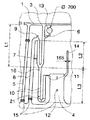
マイクロチャネルは、ミクロ機械加工方法によって形成され得、該方法においては、マイクロチャネルはディスクの表面の中にミクロ機械加工され、カバープレート例えばプラスチックフィルムがチャネルを封じるように表面に付着される。微小流体ディスク(D)は、直径よりはるかに小さい厚みを有し、遠心力によりディスクの中のマイクロチャネル内に配置される流体がディスクの外側周縁部に向かって流されるように、中心穴の周囲を回転されようとする。図1a〜図1dに示される本発明の実施形態では、マイクロチャネルは、共通の環状内側注入チャネル(1)から始まり、チャネル(1)と略同心である共通環状外側廃棄チャネル(2)で終端となる。個別の注入チャネルを有することも可能である(廃棄チャネルは、各々のマイクロチャネルのためのもの、又はマイクロチャネルのグループのためのものとなる)。マイクロチャネル構造(K7−K12)の各々の入口開口部(3)は、試薬及びサンプルの注入領域として利用され得る。各々のマイクロチャネル構造(K7−K12)には、外側廃棄チャネル(2)の中へと開く廃棄チャンバ(4)が備わる。各々のマイクロチャネル(K7−K12)は、入口開口部(3)と廃棄チャンバ(4)との間に、U字形状体積画定構造(7)とU字形状チャンバ(10)とを形成する。通常の所望の流れ方向は、入口開口部(3)から、U字形状体積画定構造(7)とU字形状チャンバ(10)とを経由して、廃棄チャンバ(4)に到る。毛管作用、圧力、及び遠心力により、即ちディスクをスピンすることにより、流れは駆動され得る。後で説明するように、疎水性ブレークも流れを制御するのに利用され得る。環状内側チャネル(1)に付加された過剰分の流体を除去するための、環状内側チャネル(1)を環状外側チャネル(2)に直接接続する輻射状伸展廃棄チャネル(5)も、示されている。
【0009】
従って、流体は、入口開口部(3)からエントランスポート(6)を経由して体積画定構造(7)の中に流れ、そこからU字形状チャンバ(10)の第1のアームの中に流れる。体積画定構造(7)は、過剰分の流体を除去するための廃棄出口、例えば輻射状伸展廃棄チャネル(8)に繋がる。その廃棄チャネル(8)は、環状外側廃棄チャネル(2)に繋がるのが好ましい。廃棄チャネル(8)は、ディスクの頂面を介して外気の中に開けるベント(9)を有するのが好ましい。ベント(9)は、ディスクの中心に最も近い廃棄チャネル(8)の一部に位置し、廃棄チャネル(8)の中の流体が体積画定構造(7)の中に引き戻されるのを防ぐ。
【0010】
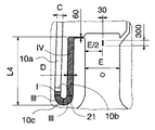
チャンバ(10)は、第1の入口アーム(10a)を有し、該アームはその下方端部にてベース(10c)に繋がり、該ベース(10c)は、第2の出口アーム(10b)の下方端部にも繋がる。チャンバ(10)は、異なる深さを備えるセクションI、II、III、IVを有してもよい。例えば、各々のセクションは、出口端部の方向の先行するセクションよりも浅くてもよく、または、セクションI及びIIIがセクションII及びIVよりも浅くてもよく、逆でもよい。限定された廃棄出口(11)、即ち狭い廃棄チャネルは、チャンバ(10)と廃棄チャンバ(4)との間に、設けられている。このことによって、体積画定構造(7)と廃棄チャネル(8)を通過する経路を経る流体の流れへの抵抗よりも、チャンバ(10)を介する流体の流れへの抵抗が、より大きいものとされる。
【0011】
廃棄チャンバ(4)の比較的大きい幅のため、微小流体デバイスの頂面と底面とが廃棄チャンバ(4)に向かって内側に傾き容積が変わってしまうことのないように、廃棄チャンバ(4)の頂面と底面とは、1つ又は複数の支持体(12)によって隔てられるのが好ましい。
【0012】
図1a〜cに示すように、体積画定構造(7)はU字形状であり、エントランスポート(6)はU字の一方のアーム(7a)の上方端部(即ちディスクの中心に最も近い端部)に開口しており、廃棄チャネル(8)はU字のもう一方のアーム(7b)の上方端部に繋がる。ベント(9)も、この他方のアーム(7b)の頂部に設けられている。U字形状の体積画定構造(7)のベース(7c)は、チャンバ(10)の第1のアーム(10a)の上方端部に繋がる。
【0013】
構造の入口(3)の注入領域に加えて、ディスクの頂面に開口し且つエントランスポート(6)に繋がる更なる注入領域(13)があってもよい。この更なる注入領域(13)は、各々の異なるミクロ構造(K7−K12)に対し異なる試薬やサンプルを加えることが所望される際に、利用され得る。
【0014】
チャンバ(10)の中に外気へのベント(14)があってもよい。アーム(7b)の中へ流体をガイドするために、チャンバ(10)の体積画定構造(7)への接続部(16)にて疎水性ブレークが設けられるのが好ましい。
【0015】
外側環状廃棄チャネル(2)は、所定の数の近接位置のマイクロチャネル構造からの廃棄を収集するように、区切られてもよい。
【0016】
疎水性ブレークは、例えば、オーバヘッドペン(パーマネントインク)(スノーマン、日本)でマークすることによって、マイクロチャネル構造(K7−K12)の中に導入され得る。(図にてクロスハッチングで示される)そのようなブレークに相応しい場所は、以下のようである。
(a)内側環状注入チャネル(1)の中のマイクロチャネル構造入口(3)の間、
(b)外側環状廃棄チャネルへの各々の開口部(15)(即ち、廃棄チャンバの開口部)、及び、
(c)存在するのならば、内側環状注入チャネル(1)と外側環状廃棄チャネル(2)とを繋ぐ輻射状廃棄チャネル(5)
である。更に、体積画定構造(7)から過剰分の流体をガイドする廃棄チャネル(8)もそうである。
【0017】
疎水性ブレークの目的は、毛管作用が流体を望まない方向へ引っ張るのを防ぐためである。疎水性ブレークは、遠心力により、即ち高速でディスクをスピンすることにより、破られ得る。
【0018】
分析されるべきサンプルが、細胞、沈殿物、粒子などの形態であるならば、(図1b及び図1d内に点線で示される)粒子フィルタ(21)によって下方Uチャネルの中で保持され得る。即ち、後で説明するように、チャンバ(10)を介する流れは、流体がチャンバを経て流れる際に粒子がチャンバの中に保持されるように、制御される。
【0019】
最初の試薬又はサンプル流体Xは、流体Xソース(図示せず。)を共通環状内側注入チャネル(1)に接続することにより、チャンバ(10)の中へ注入され得る。その共通環状内側注入チャネル(1)から、毛管作用により、及び/又はディクススピンの際の下方Uベンドへの遠心力により、流体Xが流れる。共通環状内側注入チャネル(1)の中に注入される流体Xの体積が、過剰であるならば(即ち、制限チャネル(11)のレベル(図1dの距離L4)までのチャンバ(10)の容積よりも多ければ)、図2に示すように、そのうちのいくらかは輻射状廃棄チャネル(5及び8)を介して廃棄に流れ、残りはチャンバ(10)を介して制限チャネル(11)を通り廃棄チャンバ(4)へ流れる。チャンバ(10)の左手と右手の両方の流体Xのレベルが距離L4と同じになるまで、即ち、U字形チャンバが制限チャネル(11)のレベルまで一杯になるまで、このことは継続する。このことは図2bに示されており、そこでは過剰分の流体Xは、外側廃棄チャネル(2)まで廃棄チャンバ(4)と輻射状廃棄チャネル(5及び8)を介して、若しくは制限チャネル(11)を介して、マイクロチャネル構造から流出し切っている。
【0020】
新しい試薬又はサンプル流体Yを加える際には、流体Yは共通環状内側注入チャネル(1)によって、(又は一方で、図3aに示すように)更なる注入領域(13)によって、加えられる。流体Yは、図3aに示すように、毛管作用によって体積画定構造(7)を通過して移動し、廃棄チャネル(5及び8)を下る。体積画定構造のベースと、チャンバのアーム(7a)の流体の頂部との間に含まれるエアクッション(19)が、流体がチャンバ(10)の中に流れ入るのを防ぐ障壁として作用するので、流体Yはチャンバ(10)の中に流れ込めない。チャンバ(10)内のU字ベンドのベースから制限チャネル(11)までの距離L4を、チャンバ(10)内のU字ベンドのベースから体積画定構造(7)のU字ベンドのベースまでの距離L3よりも、小さくすることによって、第1の流体Xと第2の流体Yとの間でエアクッション(19)は選択的に残され得る、ということは銘記されるべきことである。
【0021】
このことにより、第2の流体Yが毛管作用によりチャンバ(10)の中に流れ込むのを防ぐことができ、流体XとYとを混合するのも防ぐことができる。ベント(9)は、大気圧に対してオープンとなっているため、第2の流体が廃棄チャネル(2)に向かって流れることを、より容易なものにする。緩やかな、即ち低速の、ディスクのスピンにより、図3bに示すように、廃棄チャネル(8)から過剰流体Yが空になり、体積画定構造(7)を流体Yで一杯にする。
【0022】
体積画定構造(7)の中の第2の流体の体積と、第1と第2の流体の間のエアとが、チャンバ(10)の中の第1の流体Xの体積と等しいか、より多ければ、チャンバ(10)内の第1の流体Xの全ては、ディスクをスピンすることにより第2の流体Yと置換され得る。体積画定構造(7)の容積をチャンバ(10)の容積よりも確実に大きくすることによって、このことは達成され得る。体積画定構造(7)のアーム(7a)とアーム(7b)をチャンバ(10)のアームより長くし、及び/又は、体積画定構造(7)のアームの断面領域をチャンバ(10)のアームの断面領域よりも大きくすることにより、上記のことは達成され得る。ディスクがスピン中であり遠心力が流体Yを体積画定構造(7)からチャンバ(10)の中に流しよって第1の流体Xと置き換わりつつあるという、中間状況を、図4aは示す。その第1の流体は制限チャネル(11)を介して廃棄へと流れる。過剰分の第2の流体Yは、チャンバ(10)から制限チャネル(11)を介して廃棄チャンバ(4)の中に流れる。図4bは、第2の流体Yが第1の流体Xと置き換わったことを示す。このプロセスは、異なる流体を利用して、所望の回数だけ繰り返され得る。
【0023】
流体が粒子を含みそれらをチャンバの中に保持することが望まれている場合には、チャンバ(10)に適切な大きさのオリフィスを有する粒子フィルタ(21)を設置するのことが可能である。チャンバ(10)の中に粒子を一時的にのみ保持することが必要である場合には、異なる深さを有するチャンバ(10)のセクションI、II、III、IVが、粒子を一時的にトラップするのに、用いられ得る。粒子が2つのセクション間の境界壁に集まり流体は壁を超えて流れるように、ディスクの回転速度を上げることにより、このことは為される。
【0024】
本発明の別の実施形態では、粒子は、選択的にチャンバ(10’)の中に保持され得、又はチャンバ(10’)から選択的に流れ出得、その場合該チャンバ(10’)は、粒子トラップ、又は、図5に示される異なる深さを有するセクションを、備えない。このことは以下のようにして為され得る。
【0025】
チャンバ(10’)の底の中に、沈殿し、若しくは集まった粒子は、チャンバ(10’)から流れ出る流体のメニスカスにより、チャンバ(10’)から引き出され得る。換言すると、体積画定構造とチャンバ(10’)との間にエアクッション(19’)がありこれがチャンバを通って駆動されるならば、チャンバの中の流体とエアクッションとの間のメカニクスが粒子を通す際に、粒子はメカニクスにより飛沫同伴しチャンバから流出する。このことは、(“ランプ速度”として知られる)ディスクの加速度の適切な低いレートを選択することにより、為され得る。しかしながら、チャンバの中に粒子を保持することが所望されるならば、ディスクがスピンする際に体積画定構造の中の流体によってエアクッションがチャンバ(10’)を通って駆動されないことを保証することが必要である。ディスク加速度の適切な高レートが選択されるならば、体積画定構造の流体が、チャネルの側面を下り、エアクッション(19’)を通り、エアクッション(19’)を置き換えることなく、流れることが可能である。3500rpm/秒2までのランプ速度は、チャネルシステム内で更に粒子を運ぶのが、通常である。3500rpm/秒2より大きいランプ速度により、流体/気体インタフェース(メニスカス)はUチャンバに入らず、気泡は静止しているか、若しくは遠心力と反対方向に移動する。所望の効果を達成するための正確なランプ速度は、利用される流体のタイプに通常依存し、実験によって最も適切に決定される。
【0026】
図6に示される本発明の別の実施形態では、体積画定構造(7’)のアーム(7b’)が、廃棄チャネル(8)に繋がっておらず、その代わりに、流体がベント(9’)からオーバフローするのを防ぐ流体貯蔵部を形成するため、ディスクの中心に最も近い端部で拡張されている。このベント及び/又はサンプル入口(9’)はこの貯蔵部(61)に大気への口を作り、サンプルを構造の中に注入させる。貯蔵部(61)は、体積画定構造の長さ、即ち貯蔵部(61)及びアーム(7b’)の長さを、アーム(7a’)の長さと等しいものとする、若しくはより長いものとする、長さを有するのが好ましい。体積画定構造(7’)がスピンにより充填されている際に流体の表面張力によりベント(9’)から流出しえない程、ベント(9’)が小さいならば、体積画定構造(7’)に入り得る流体の量は最小限となり、流体は廃棄されない。チャンバ(10)の流体全てを体積画定構造からの流体で置き換えるのならば、当然ながら、体積画定構造の容積はチャンバ(10)の容積よりも大きくなければならない。チャンバのアーム(10a)が、上方端部から下方端部へと広がって形成されているならば、第2の流体を加える際に2つの流体を混合しないで、チャンバからエア障害(19)を押し出すことが可能である。
【0027】
本発明のチャンバの全てには、図7でクロスハッチで示されているような、コーティングの形態での加熱手段が、設置され得る。このコーティング(71)は、チャンバの近傍でディスクの片面又は両面に、ペイントされ、又はプリントされ、又は他の方法で塗布され得るのであるが、それに向けられた電磁放射からエネルギを吸収しチャンバを加熱する。入射輻射は、赤外線、レーザ光、可視光、紫外線、マイクロウエーブ、又は他のどんなタイプの輻射であってもよい。チャンバの加熱は、チャンバ内の反応を起こし、若しくは促進するのに利用され得る。チャンバが加熱されている間ディスクが静止しているならば、流体が沸くと流体は、チャンバのアームを上昇し更に廃棄チャネル(8)及び廃棄チャンバ(4)の中にまで透過しうる蒸気の泡を生成してしまう。加熱が終了した後実質的に流体の全てがチャンバの中にあるのが望ましいことが多いので、このことが常に好ましいわけではない。本発明では、輻射がコーティング(71)に入射する際に同時にディスクをスピンすることによって、このことが為され得る。輻射ソース(図示せず。)は、ディスクがスピンする際にコーティングが通過する領域上に焦点合わせされる。更に、熱は、試薬の十分な熱と一致する最小限のベース量のみ加えられるように、コーティングは寸法取りされ得る。このように、U字形のアームは低温を保ち、流体の蒸気を凝結するための凝結面を配設する。凝結された蒸気に作用する遠心力により、チャンバのベースの中に流し戻される。
【0028】
上述の発明の実施形態は廃棄チャンバに先行するチャンバを有するが、勿論チャンバ出口が一つ又は複数のチャンバに先行することも想定され得るということが銘記されるべきである。各々の更なるチャンバは、サンプル及び試薬がチャンバ内で結合されるように、複数の入口と複数の出口を備えてもよい。チャンバ内で生じるプロセスのその後の成果物は、更なるプロセスのために一つ又は複数のチャンバに分配され、又は廃棄チャネルに送られる。この例が図8に示されている。図8は、図6に示されるのと同様の設計のミクロ構造を示し、該構造では、U字形状チャンバ(110)のベース(110c)がベース出口チャネル(134)により第2のチャンバ(136)に繋がり、その第2のチャンバ(136)は、第2のチャンバ(110)よりもよりディスクの中心から離れて配置される。第2のチャンバ(136)は、ディスクの頂面にて開口するベント(138)により大気に排口する。第2のチャンバ(136)には、ディスクの頂面にてやはり開口する入口/出口接合部(140)も配設される。入口/出口(140)は、例えば接合部(140)の中に物質を注入することによって、第2のチャンバ(136)に物質を供給するのに、更に/若しくは、例えば接合部(140)を介して物質を吸い込むことによって、第2のチャンバ(136)から物質を抜き取るのに、利用され得る。チャンバ(110)のベース(110c)とベース出口チャネル(134)との間の接合点(130)に又はその近傍に配置される疎水性ブレーク(132)によって、毛管作用によりチャンバ(110)からベース出口チャネル(134)の中に流体が流れ込むのが、防がれる。ディスクが毎秒ある回転数でスピンするときはチャンバ(110)の流体はチャンバ出口アーム(110b)を介してチャンバから出ていき、ディスクが毎分より高速の回転数でスピンするときは流体に作用する遠心力が疎水性ブレーク(132)の疎水性効果を乗り越えるのに十分なものとなり流体が第2のチャンバ(136)の中に流れ込むように、疎水性ブレーク(132)は寸法取りされる。本発明のこの実施形態では、チャンバ(110)の出口アーム(110b)は、入口アーム(110a)と殆ど同程度の長さである。従って、チャンバ(110)が流体で満たされていると、入口アーム(110a)の流体のレベルは、体積画定構造(107’)のベース(107c’)に非常に近くなる。第2の流体が例えば貯蔵部(161)の入口(109’)を介して体積画定構造(107’)に供給されるとき、チャンバ(110)の中の第1の流体と直接接触し2つの流体の間で泡を生じない、ということを、このことは意味する。この構成は、2つの流体の混合を促進するのに利用される。
【0029】
想定され得る実施形態に係る上述の例は、本発明を例示することを意図するものであり、添付の請求項により請求される保護範囲を限定することを意図するものではない。
【図面の簡単な説明】
【図1a】 本発明に従い、5つの輻射状に伸展するマイクロチャネル構成K7−K12を有する、遠心ロータの周辺部分を示す。
【図1b】 本発明に係る図1aからの一つのマイクロチャネルの構成の拡大図を示す。
【図1c】 図1bのマイクロチャネルの構成の中のサンプル体積画定構造の拡大図を示す。
【図1d】 廃棄流体を処分するチャンバを加えたチャンバ領域の拡大図を示し、深さの変動はクロスハッチングで示される。
【図2a】 第1の流体を含むチャンバを伴う図1bの構成を示す。
【図2b】 第1の流体を含むチャンバを伴う図1bの構成を示す。
【図3a】 体積画定チャンバに第2の流体を付加した様子を示す。
【図3b】 体積画定チャンバに第2の流体を付加した様子を示す。
【図4a】 チャンバの中の第1の流体が上記の第2の流体によって置換される様子を示す。
【図4b】 チャンバの中の第1の流体が上記の第2の流体によって置換される様子を示す。
【図5】 本発明に係るマイクロチャネルの構成の第2の実施形態を示す。
【図6】 本発明に係るマイクロチャネルの構成の第3の実施形態を示す。
【図7】 本発明に係るマイクロチャネルの構成の第4の実施形態を示す。
【図8】 本発明に係るマイクロチャネルの構成の第5の実施形態を示す。[0001]
FIELD OF THE INVENTION The present invention relates to a microanalyzer and a method for moving fluids with the device.
[0002]
Prior art proposals apply to microanalytical systems based on microchannels formed in rotating (usually plastic) disks, often referred to as “centrifugal rotors” or “labs on chips” Not limited). Such discs can be utilized to perform small volume fluid analysis and separation. In order to reduce costs, the disc is preferably not limited to being used with only one type of reagent or fluid, but can function with a variety of fluids. Further, in sample preparation, it is preferred that the user can dispense the exact volume of any combination of fluids or samples without modifying the disk. Because the microchannel is narrow, any bubbles that exist between the two fluid samples in the microchannel can act as a separation barrier, i.e., block the microchannel, and are therefore supposed to enter the fluid. May interfere with entering the microchannel. To overcome this problem, US Pat. No. 5,591,643 discloses a centrifugal rotor having a microchannel with a cross-sectional area large enough to allow unwanted air to be discharged from the microchannel while fluid enters the microchannel. Is disclosed.
[0003]
Objects of the Invention An object of the present invention is to provide a configuration of a centrifugal rotor and a method of using the centrifugal rotor that achieves reliable fluid transfer in the centrifugal rotor.
[0004]
It is a further object of the present invention to provide a centrifugal rotor configuration and method for utilizing the centrifugal rotor that achieves accurate fluid measurement in the centrifugal rotor.
[0005]
Summary of the Invention The present invention achieves the object of the invention with the structure having the features of
[0006]
Detailed Description of Embodiments Showing the Invention A microchannel configuration (K7-K12) according to the present invention is shown in FIGS. 1a-d and is formed radially on a microfluidic disk (D).
[0007]
The microfluidic disk is preferably a one-piece or two-piece mold structure, preferably formed from an optional transparent plastic or polymer material by a separate mold. The separation molds are combined (eg, by heating) into a closed configuration with openings in place to load the device with fluid and remove the fluid sample. Suitable plastics for the polymer material may be selected to provide hydrophobic properties. Suitable plastic or polymer materials are selected from polystyrene and polycarbonate. On the other hand, the surface of the microchannel may additionally be added by chemical or physical means that alter the surface properties so as to create local regions that give the desired properties of hydrophobic or hydrophilic properties within the microchannel. And optionally, it may be improved. Suitable plastics are selected from polymers with charged surfaces, desirably chemically or ion plasma treated polyesters, polycarbonates, or other rigid transparent polymers.
[0008]
The microchannel may be formed by a micromachining method, in which the microchannel is micromachined into the surface of the disc and a cover plate, such as a plastic film, is attached to the surface to seal the channel. The microfluidic disk (D) has a thickness that is much smaller than the diameter, so that the fluid placed in the microchannels in the disk is caused to flow toward the outer peripheral edge of the disk by centrifugal force. Try to rotate around. In the embodiment of the invention shown in FIGS. 1a-1d, the microchannel starts with a common annular inner injection channel (1) and terminates with a common annular outer waste channel (2) that is substantially concentric with the channel (1). It becomes. It is also possible to have a separate injection channel (the waste channel will be for each microchannel or group of microchannels). Each inlet opening (3) of the microchannel structure (K7-K12) can be utilized as an injection region for reagents and samples. Each microchannel structure (K7-K12) is provided with a waste chamber (4) that opens into the outer waste channel (2). Each microchannel (K7-K12) forms a U-shaped volume defining structure (7) and a U-shaped chamber (10) between the inlet opening (3) and the waste chamber (4). The normal desired flow direction reaches the waste chamber (4) from the inlet opening (3) via the U-shaped volume defining structure (7) and the U-shaped chamber (10). The flow can be driven by capillary action, pressure and centrifugal force, i.e. by spinning the disk. As will be explained later, hydrophobic breaks can also be utilized to control flow. Also shown is a radial extension waste channel (5) that directly connects the annular inner channel (1) to the annular outer channel (2) to remove excess fluid added to the annular inner channel (1). Yes.
[0009]
Thus, fluid flows from the inlet opening (3) via the entrance port (6) into the volume defining structure (7) and from there into the first arm of the U-shaped chamber (10). . The volume-defining structure (7) leads to a waste outlet for removing excess fluid, for example a radial extension waste channel (8). The waste channel (8) preferably leads to an annular outer waste channel (2). The waste channel (8) preferably has a vent (9) that opens into the outside air through the top surface of the disk. The vent (9) is located in the part of the waste channel (8) closest to the center of the disc and prevents the fluid in the waste channel (8) from being drawn back into the volume defining structure (7).
[0010]
The chamber (10) has a first inlet arm (10a), which is connected at its lower end to a base (10c), the base (10c) being connected to the second outlet arm (10b). Also connected to the lower end. The chamber (10) may have sections I, II, III, IV with different depths. For example, each section may be shallower than the preceding section in the direction of the exit end, or sections I and III may be shallower than sections II and IV, and vice versa. A limited waste outlet (11), ie a narrow waste channel, is provided between the chamber (10) and the waste chamber (4). This makes the resistance to fluid flow through the chamber (10) greater than the resistance to fluid flow through the path through the volume defining structure (7) and the waste channel (8). The
[0011]
Due to the relatively large width of the waste chamber (4), the top and bottom surfaces of the microfluidic device are tilted inward toward the waste chamber (4) so that the volume does not change. Preferably, the top and bottom surfaces are separated by one or more supports (12).
[0012]
As shown in FIGS. 1a-c, the volume defining structure (7) is U-shaped and the entrance port (6) is the upper end of one U-shaped arm (7a) (ie, the end closest to the center of the disc). The waste channel (8) is connected to the upper end of the other U-shaped arm (7b). A vent (9) is also provided on the top of the other arm (7b). The base (7c) of the U-shaped volume defining structure (7) is connected to the upper end of the first arm (10a) of the chamber (10).
[0013]
In addition to the injection area at the entrance (3) of the structure, there may be a further injection area (13) opening at the top of the disk and leading to the entrance transport (6). This additional injection region (13) can be utilized when it is desired to add different reagents and samples to each different microstructure (K7-K12).
[0014]
There may be a vent (14) to the outside air in the chamber (10). In order to guide the fluid into the arm (7b), a hydrophobic break is preferably provided at the connection (16) to the volume defining structure (7) of the chamber (10).
[0015]
The outer annular waste channel (2) may be partitioned to collect waste from a predetermined number of closely spaced microchannel structures.
[0016]
Hydrophobic breaks can be introduced into the microchannel structure (K7-K12), for example by marking with an overhead pen (permanent ink) (Snowman, Japan). Suitable places for such a break (shown with cross-hatching in the figure) are:
(A) during the microchannel structure inlet (3) in the inner annular injection channel (1);
(B) each opening (15) to the outer annular waste channel (i.e. the opening of the waste chamber), and
(C) If present, a radial waste channel (5) connecting the inner annular injection channel (1) and the outer annular waste channel (2).
It is. In addition, the waste channel (8) guiding excess fluid from the volume defining structure (7).
[0017]
The purpose of the hydrophobic break is to prevent capillary action from pulling the fluid in an undesired direction. Hydrophobic breaks can be broken by centrifugal force, i.e. by spinning the disk at high speed.
[0018]
If the sample to be analyzed is in the form of cells, precipitates, particles, etc., it can be retained in the lower U channel by a particle filter (21) (shown in dotted lines in FIGS. 1b and 1d). That is, as will be described later, the flow through the chamber (10) is controlled so that the particles are retained in the chamber as fluid flows through the chamber.
[0019]
The initial reagent or sample fluid X can be injected into the chamber (10) by connecting a fluid X source (not shown) to the common annular inner injection channel (1). From its common annular inner injection channel (1), fluid X flows by capillary action and / or by centrifugal force to the lower U-bend during dex spin. The volume of the fluid X that is injected into the common annular inner inlet channel (1) is, if it is excessive (i.e., up to the level of the restricted channels (11) (FIG. 1 d Distance L4) chamber (10) 2), some of them flow to waste through the radial waste channels (5 and 8) and the rest pass through the restriction channel (11) through the chamber (10), as shown in FIG. Flow to waste chamber (4). This continues until the level of fluid X in both the left and right hands of the chamber (10) is equal to the distance L4, i.e. until the U-shaped chamber is full to the level of the limiting channel (11). This is illustrated in FIG. 2b , where excess fluid X passes through the waste chamber (4) and the radial waste channels (5 and 8) to the outer waste channel (2), or the restricted channel. Through (11), it has completely flowed out of the microchannel structure.
[0020]
When adding a new reagent or sample fluid Y is by a fluid Y common annular inner inlet channel (1), depending on (or one, as shown in FIG. 3 a) further injection region (13), was added It is done. Fluid Y, as shown in FIG. 3 a, to move through the volume defined structure (7) by capillary action, down the waste channel (5 and 8). Since the air cushion (19) contained between the base of the volume defining structure and the fluid top of the chamber arm (7a) acts as a barrier to prevent fluid from flowing into the chamber (10) , Fluid Y cannot flow into the chamber (10). The distance L4 from the base of the U-bend in the chamber (10) to the restriction channel (11) is the distance from the base of the U-bend in the chamber (10) to the base of the U-bend in the volume defining structure (7). It should be noted that by making it smaller than L3, the air cushion (19) can be selectively left between the first fluid X and the second fluid Y.
[0021]
This can prevent the second fluid Y from flowing into the chamber (10) by capillary action, and can also prevent the fluids X and Y from being mixed. Since the vent (9) is open to atmospheric pressure, it makes it easier for the second fluid to flow towards the waste channel (2) . Gradual, i.e. the low speed, the spin of the disk, as shown in FIG. 3 b, excess fluid Y from waste channel (8) is empty, a volume defining structure (7) is filled with fluid Y.
[0022]
The volume of the second fluid in the volume defining structure (7) and the air between the first and second fluids are equal to or greater than the volume of the first fluid X in the chamber (10) If so, all of the first fluid X in the chamber (10) can be replaced with the second fluid Y by spinning the disk. This can be achieved by ensuring that the volume of the volume defining structure (7) is larger than the volume of the chamber (10). The arms (7a) and (7b) of the volume defining structure (7) are longer than the arms of the chamber (10) and / or the cross-sectional area of the arms of the volume defining structure (7) is By making it larger than the cross-sectional area, the above can be achieved. FIG. 4a shows an intermediate situation where the disk is spinning and centrifugal force is replacing fluid first by flowing fluid Y from the volume defining structure (7) into chamber (10). The first fluid flows to the waste through the restriction channel (11). Excess second fluid Y flows from chamber (10) through restriction channel (11) into waste chamber (4). FIG. 4 b shows that the second fluid Y has replaced the first fluid X. This process can be repeated as many times as desired utilizing different fluids.
[0023]
If the fluid contains particles and it is desired to hold them in the chamber, it is possible to install a particle filter (21) with an appropriately sized orifice in the chamber (10). . If it is necessary to only temporarily hold the particles in the chamber (10), sections I, II, III, IV of the chamber (10) having different depths temporarily trap the particles. Can be used to This is done by increasing the rotational speed of the disk so that the particles collect on the boundary wall between the two sections and the fluid flows across the wall.
[0024]
In another embodiment of the invention, the particles can be selectively retained in the chamber (10 ′) or can selectively flow out of the chamber (10 ′), in which case the chamber (10 ′) There is no particle trap or section with different depths shown in FIG. This can be done as follows.
[0025]
Particles that settle or collect in the bottom of the chamber (10 ′) can be withdrawn from the chamber (10 ′) by a meniscus of fluid flowing out of the chamber (10 ′). In other words, if there is an air cushion (19 ') between the volume defining structure and the chamber (10') and it is driven through the chamber, the mechanics between the fluid in the chamber and the air cushion is When passing through, the particles are entrained by the mechanics and flow out of the chamber. This can be done by selecting an appropriate low rate of disk acceleration (known as "ramp speed"). However, if it is desired to retain the particles in the chamber, ensure that the air cushion is not driven through the chamber (10 ') by the fluid in the volume defining structure as the disk spins. is required. If a suitable high rate of disk acceleration is selected, the volume-defining fluid can flow down the side of the channel, through the air cushion (19 '), without replacing the air cushion (19'). Is possible. A ramp rate of up to 3500 rpm / sec 2 usually carries more particles in the channel system. With a ramp speed greater than 3500 rpm / sec 2 , the fluid / gas interface (meniscus) does not enter the U-chamber and the bubble is stationary or moves in the opposite direction to the centrifugal force. The exact ramp rate to achieve the desired effect usually depends on the type of fluid utilized and is best determined by experiment.
[0026]
In another embodiment of the invention shown in FIG. 6, the arm (7b ′) of the volume-defining structure (7 ′) is not connected to the waste channel (8); instead, the fluid is vented (9 ′ ) Is extended at the end closest to the center of the disk to form a fluid reservoir to prevent overflow from. The vent and / or sample inlet (9 ') creates an opening to the atmosphere in the reservoir (61) and allows the sample to be injected into the structure. The reservoir (61) has the length of the volume defining structure, that is, the length of the reservoir (61) and the arm (7b ′) equal to or longer than the length of the arm (7a ′). , Preferably having a length. If the vent (9 ′) is so small that the surface tension of the fluid cannot flow out of the vent (9 ′) when the volume defining structure (7 ′) is filled with spin, the volume defining structure (7 ′) The amount of fluid that can enter is minimized and the fluid is not discarded. Of course, if all of the fluid in the chamber (10) is replaced by fluid from the volume defining structure, the volume of the volume defining structure must be greater than the volume of the chamber (10). If the chamber arm (10a) is formed extending from the upper end to the lower end, the two fluids are not mixed when adding the second fluid, and the air obstruction (19) is removed from the chamber. It is possible to extrude.
[0027]
All of the chambers of the present invention may be provided with heating means in the form of a coating, as shown by the cross hatch in FIG. This coating (71), which can be painted or printed or otherwise applied to one or both sides of the disc in the vicinity of the chamber, absorbs energy from electromagnetic radiation directed at it and Heat. The incident radiation may be infrared, laser light, visible light, ultraviolet light, microwave, or any other type of radiation. Chamber heating can be utilized to initiate or promote reactions in the chamber. If the disk is stationary while the chamber is heated, when the fluid boils, the fluid rises up the arm of the chamber and further penetrates into the waste channel (8) and waste chamber (4). Bubbles are generated. This is not always preferred because it is often desirable that substantially all of the fluid is in the chamber after heating is complete. In the present invention, this can be done by spinning the disk simultaneously when radiation is incident on the coating (71). A radiation source (not shown) is focused on the area through which the coating passes as the disk spins. Furthermore, the coating can be dimensioned so that heat is applied only in a minimal base amount consistent with sufficient heat of the reagent. Thus, the U-shaped arm maintains a low temperature and is provided with a condensation surface for condensing the vapor of the fluid. Centrifugal force acting on the condensed steam is forced back into the base of the chamber.
[0028]
It should be noted that although the embodiments of the invention described above have a chamber that precedes the waste chamber, it is of course also possible that the chamber outlet precedes one or more chambers. Each additional chamber may comprise a plurality of inlets and a plurality of outlets so that sample and reagent are combined within the chamber. Subsequent deliverables of the process that occurs in the chamber are distributed to one or more chambers for further processing or sent to a waste channel. An example of this is shown in FIG. FIG. 8 shows a microstructure of a design similar to that shown in FIG. 6, in which the base (110c) of the U-shaped chamber (110) is connected to the second chamber (136) by the base outlet channel (134). ) And its second chamber (136) is located farther from the center of the disc than the second chamber (110). The second chamber (136) is vented to the atmosphere by a vent (138) that opens at the top surface of the disk. The second chamber (136) is also provided with an inlet / outlet joint (140) that also opens at the top surface of the disk. The inlet / outlet (140) can be used to supply material to the second chamber (136), eg, by injecting material into the joint (140), and / or, for example, the joint (140). Can be utilized to withdraw material from the second chamber (136) by inhaling the material through. Base from the chamber (110) by capillary action by a hydrophobic break (132) located at or near the junction (130) between the base (110c) and the base outlet channel (134) of the chamber (110). Fluid is prevented from flowing into the outlet channel (134). When the disc spins at a certain number of revolutions per second, the fluid in the chamber (110) exits the chamber via the chamber exit arm (110b), and acts on the fluid when the disc spins at a faster revolution rate per minute. The hydrophobic break (132) is dimensioned so that the centrifugal force to be sufficient to overcome the hydrophobic effect of the hydrophobic break (132) and fluid flows into the second chamber (136). In this embodiment of the invention, the outlet arm (110b) of the chamber (110) is almost as long as the inlet arm (110a). Thus, when the chamber (110) is filled with fluid, the fluid level of the inlet arm (110a) is very close to the base (107c ') of the volume defining structure (107'). When the second fluid is supplied to the volume defining structure (107 ′), for example, via the inlet (109 ′) of the reservoir (161), the two fluids are in direct contact with the first fluid in the chamber (110). This means that there are no bubbles between the fluids. This configuration is utilized to facilitate mixing of the two fluids.
[0029]
The above examples of possible embodiments are intended to illustrate the present invention and are not intended to limit the scope of protection claimed by the appended claims.
[Brief description of the drawings]
FIG. 1a shows a peripheral portion of a centrifugal rotor with five radially extending microchannel configurations K7-K12 according to the present invention.
1b shows an enlarged view of the configuration of one microchannel from FIG. 1a according to the present invention.
FIG. 1c shows an enlarged view of a sample volume defining structure in the microchannel configuration of FIG. 1b.
FIG. 1d shows an enlarged view of the chamber area plus a chamber for disposing of waste fluid, with depth variations shown as cross-hatching.
FIG. 2a shows the configuration of FIG. 1b with a chamber containing a first fluid.
FIG. 2b shows the configuration of FIG. 1b with a chamber containing a first fluid.
FIG. 3a shows the addition of a second fluid to the volume definition chamber.
FIG. 3b shows the addition of a second fluid to the volume definition chamber.
FIG. 4a shows the first fluid in the chamber being replaced by the second fluid.
FIG. 4b shows the first fluid in the chamber being replaced by the second fluid.
FIG. 5 shows a second embodiment of a microchannel configuration according to the present invention.
FIG. 6 shows a third embodiment of a microchannel configuration according to the present invention.
FIG. 7 shows a fourth embodiment of the configuration of the microchannel according to the present invention.
FIG. 8 shows a fifth embodiment of the configuration of the microchannel according to the present invention.
Claims (9)
該ミクロ構造が、U字形状体積画定構造(7、107)を含み、
該U字形状体積画定構造(7、107)が、
上方端部にて又は上方端部近傍にてエントランスポート(6)へ繋がる第1のアーム(7a)であって、その下方端部は、エントランスポート(6)よりもディスク(D)中心から遠いか、又は、エントランスポート(6)と同じくらいディスク(D)中心と距離を持つような、第1のアーム(7a)と、
上方端部にて又は上方端部近傍にて、第1の廃棄チャネル(8)へ、又はサンプル入口へ即ち流体貯蔵部(61、161)を経由してベント(9’、109’)へ繋がる第2のアーム(7b)であって、もし備わるなら該第1の廃棄チャネル(8)は該エントランスポート(6)よりもディスク(D)の中心から遠い、第2のアーム(7b)と、
上記第1と第2のアーム(7a、7b)よりもディスク(D)の中心から離れて配置され、上記第1と第2のアーム(7a、7b)の下方端部と繋がるベース(7c)であって、上記U字形状体積画定構造の少なくとも第1のアーム(7a)が、上記入口ポート(6)から上記U字形状体積画定構造内に毛管作用により流体を駆動するようにされており、ベース(7c)は、U字形状チャンバ(10、110)の入口アーム(10a、110a)と該入口アーム(10a、110a)の上方端部にて又は上方端部近傍にて繋がる、ベース(7c)と
を含み、
更に、上記U字形状チャンバ(10、110)は、ベース(10c、110c)と出口アーム(10b、110b)を含み、
上記ベース(10c、110c)は、上記入口アーム(10a、110a)の下方端部を上記出口アーム(10b、110b)の下方端部へ繋ぎ、上記出口アーム(10b、110b)は上方端部にて又は上方端部近傍にて第2の廃棄出口(11)に繋がり、上記ベース(10c、110c)は、上記U字形状チャンバ(10、110)の上記入口と出口のアーム(10a、10b;110a、110b)の下方端部よりもディスク(D)中心から遠いか、又は、同じくらいのディスク(D)中心からの距離を持つ、
ミクロ構造。In the microstructure for the fluid installed in the rotating disk (D),
The microstructure comprises a U-shaped volume defining structure (7, 107);
The U-shaped volume defining structure (7, 107) is
A first arm (7a) connected to the entrance port (6) at or near the upper end, the lower end being farther from the center of the disc (D) than the entrance port (6) Or a first arm (7a) having a distance from the center of the disk (D) as much as the entrance transport (6);
At the upper end or near the upper end leads to the first waste channel (8) or to the sample inlet, ie via the fluid reservoir (61, 161) to the vent (9 ′, 109 ′). A second arm (7b), wherein if provided, the first discard channel (8) is farther from the center of the disc (D) than the entrance transport (6);
A base (7c) which is arranged farther from the center of the disk (D) than the first and second arms (7a, 7b) and is connected to the lower ends of the first and second arms (7a, 7b ). Wherein at least a first arm (7a) of the U-shaped volume defining structure is adapted to drive fluid by capillary action from the inlet port (6) into the U-shaped volume defining structure. The base (7c) is connected to the inlet arm (10a, 110a ) of the U-shaped chamber (10, 110) and the upper end of the inlet arm (10a, 110a) or in the vicinity of the upper end ( 7c),
Further, the U-shaped chamber (10, 110) includes a base (10c, 110c) and an outlet arm (10b, 110b),
The base (10c, 110c) connects the lower end of the inlet arm (10a, 110a) to the lower end of the outlet arm (10b, 110b), and the outlet arm (10b, 110b) is connected to the upper end. Or in the vicinity of the upper end, the base (10c, 110c) is connected to the inlet and outlet arms (10a, 10b) of the U-shaped chamber (10, 110); 110a, 110b) farther from the center of the disk (D) than the lower end of the disk 110D, or about the same distance from the center of the disk (D),
Microstructure.
請求項1に記載のミクロ構造。A vent (9) is installed in the first waste channel (8),
The microstructure of claim 1.
請求項1に記載のミクロ構造。The second arm (7b) is connected to the vent, ie to the sample inlet (9 ′, 109 ′),
The microstructure of claim 1.
請求項1乃至請求項3のうちのいずれか一つに記載のミクロ構造。The fluid flow resistance through the second waste outlet (11) is greater than the fluid flow resistance through the first waste channel (8),
The microstructure according to any one of claims 1 to 3.
請求項1乃至請求項4のうちのいずれか一つに記載のミクロ構造。The length of the U-shaped volume defining structure (7, 107) is longer than the length of the U-shaped chamber (10, 110),
The microstructure according to any one of claims 1 to 4.
請求項1乃至請求項5のうちのいずれか一つに記載のミクロ構造。The U-shaped chamber (10, 110) is at least partially covered with a coating (71), which absorbs energy from electromagnetic radiation directed thereto and dampens the U-shaped chamber (10). Characterized by heating,
The microstructure according to any one of claims 1 to 5.
請求項1乃至請求項6のうちのいずれか一つに記載のミクロ構造。 Characterized in that the U-shaped chamber (10, 110) has sections I, II, III, IV with different depths, which can be used to capture and release sedimentary substances and other particles,
The microstructure according to any one of claims 1 to 6.
上記U字形状チャンバ(110)よりも上記ディスク(D)中央から離れて配置される第2のチャンバ(136)にチャネル(134)によって繋げられ、
U字形状チャンバ(110)とチャネル(132)との間の接合点にて又は接合点近傍にて、疎水性ブレーク(132)が設置されることを特徴とする、
請求項1乃至請求項7のうちのいずれか一つに記載のミクロ構造。The U-shaped chamber (110) near the base (110c)
The U-shaped chamber (110) is connected to a second chamber (136) arranged farther from the center of the disk (D) than the U-shaped chamber (110) by a channel (134),
Characterized in that a hydrophobic break (132) is placed at or near the junction between the U-shaped chamber (110) and the channel (132).
The microstructure according to any one of claims 1 to 7.
上記U字形状体積画定構造(7)を、置き換えるべき流体で満たすステップと、
遠心力の下で上記の置き換えるべき流体が上記チャンバの中に入り込み、それと同時にU字形状チャンバ(10)の中の元の流体は、入り込んでくる置き換えるべき流体によってU字形状チャンバからの退去を強制されるステップとを含むことを特徴とする、
回転ディスク(D)の中のU字形状チャンバ(10、110)の元からの流体を置き換える方法。Disposing a microstructure containing an original fluid in a U-shaped chamber (10, 110) according to any one of claims 1 to 8,
Filling the U-shaped volume defining structure (7) with the fluid to be replaced;
Under centrifugal force, the fluid to be replaced enters the chamber and at the same time the original fluid in the U-shaped chamber (10) is displaced from the U-shaped chamber by the fluid to be replaced. Including a forced step,
A method of replacing the fluid from the origin of the U-shaped chamber (10, 110) in the rotating disk (D).
Applications Claiming Priority (5)
| Application Number | Priority Date | Filing Date | Title |
|---|---|---|---|
| PCT/EP1999/010347 WO2000040750A1 (en) | 1998-12-30 | 1999-12-23 | Method for sequencing dna using a microfluidic device |
| EP99/10347 | 1999-12-23 | ||
| SE0001779A SE0001779D0 (en) | 2000-05-12 | 2000-05-12 | Microanalysis device |
| SE0001779-8 | 2000-05-12 | ||
| PCT/EP2000/013145 WO2001046465A2 (en) | 1999-12-23 | 2000-12-22 | Microfluid analysis device |
Publications (3)
| Publication Number | Publication Date |
|---|---|
| JP2003518250A JP2003518250A (en) | 2003-06-03 |
| JP2003518250A5 JP2003518250A5 (en) | 2008-02-28 |
| JP4612262B2 true JP4612262B2 (en) | 2011-01-12 |
Family
ID=20279665
Family Applications (1)
| Application Number | Title | Priority Date | Filing Date |
|---|---|---|---|
| JP2001546961A Expired - Lifetime JP4612262B2 (en) | 1999-12-23 | 2000-12-22 | Micro analyzer |
Country Status (7)
| Country | Link |
|---|---|
| JP (1) | JP4612262B2 (en) |
| AT (1) | ATE367204T1 (en) |
| AU (1) | AU4410501A (en) |
| CA (1) | CA2395159A1 (en) |
| DE (1) | DE60035611T2 (en) |
| SE (1) | SE0001779D0 (en) |
| WO (1) | WO2001046465A2 (en) |
Families Citing this family (34)
| Publication number | Priority date | Publication date | Assignee | Title |
|---|---|---|---|---|
| US7026131B2 (en) | 2000-11-17 | 2006-04-11 | Nagaoka & Co., Ltd. | Methods and apparatus for blood typing with optical bio-discs |
| US7087203B2 (en) | 2000-11-17 | 2006-08-08 | Nagaoka & Co., Ltd. | Methods and apparatus for blood typing with optical bio-disc |
| SE0004296D0 (en) | 2000-11-23 | 2000-11-23 | Gyros Ab | Device and method for the controlled heating in micro channel systems |
| SE0004297D0 (en) | 2000-11-23 | 2000-11-23 | Gyros Ab | Device for thermal cycling |
| US7079468B2 (en) | 2000-12-08 | 2006-07-18 | Burstein Technologies, Inc. | Optical discs for measuring analytes |
| US7054258B2 (en) | 2000-12-08 | 2006-05-30 | Nagaoka & Co., Ltd. | Optical disc assemblies for performing assays |
| US7091034B2 (en) | 2000-12-15 | 2006-08-15 | Burstein Technologies, Inc. | Detection system for disk-based laboratory and improved optical bio-disc including same |
| US7429354B2 (en) | 2001-03-19 | 2008-09-30 | Gyros Patent Ab | Structural units that define fluidic functions |
| CA2441206A1 (en) | 2001-03-19 | 2002-09-26 | Gyros Ab | Characterization of reaction variables |
| US6919058B2 (en) | 2001-08-28 | 2005-07-19 | Gyros Ab | Retaining microfluidic microcavity and other microfluidic structures |
| EP1483052B1 (en) * | 2001-08-28 | 2010-12-22 | Gyros Patent Ab | Retaining microfluidic microcavity and other microfluidic structures |
| ATE477054T1 (en) | 2001-09-17 | 2010-08-15 | Gyros Patent Ab | FUNCTIONAL UNIT ALLOWING CONTROLLED FLOW IN A MICROFLUID DEVICE |
| JP4368681B2 (en) * | 2001-09-17 | 2009-11-18 | ユィロス・パテント・アクチボラグ | Functional unit that enables control of flow in microfluidic devices |
| CN100382870C (en) * | 2001-12-28 | 2008-04-23 | 株式会社日立高新技术 | Extractor, chemical analyzer and chemical analyzing method |
| JP4338529B2 (en) | 2002-04-08 | 2009-10-07 | ユロス・パテント・アクチボラゲット | Homing process |
| DE60328392D1 (en) * | 2002-04-30 | 2009-08-27 | Gyros Patent Ab | BY MEANS OF AN INTEGRATED MICROFLUIDIC DEVICE |
| CN1650173B (en) * | 2002-04-30 | 2012-06-06 | 爱科来株式会社 | Analysis instrument, sample analysis method and analysis device using the instrument, and method of forming opening in the instrument |
| US7005265B1 (en) | 2002-06-20 | 2006-02-28 | Wenhong Fan | Nonenzymatic catalytic signal amplification for nucleic acid hybridization assays |
| ATE464559T1 (en) | 2002-10-13 | 2010-04-15 | Picosep As | TWO-DIMENSIONAL MICROFLUIDIC SYSTEM FOR THE SEPARATION OF BIOMOLECULES |
| SE0301945D0 (en) | 2003-06-30 | 2003-06-30 | Gyros Ab | Confidence determination |
| JPWO2005012916A1 (en) * | 2003-08-05 | 2006-09-21 | 太陽誘電株式会社 | Sample analyzer and disk-shaped sample analysis medium |
| US20090050620A1 (en) * | 2004-01-06 | 2009-02-26 | Gyros Ab | Contact heating arrangement |
| EP1874469A4 (en) | 2005-04-14 | 2014-02-26 | Gyros Patent Ab | A microfluidic device with finger valves |
| GB2464721C (en) | 2008-10-23 | 2013-08-14 | Biosurfit Sa | Jet deflection device |
| GB2466644B (en) | 2008-12-30 | 2011-05-11 | Biosurfit Sa | Liquid handling |
| JP5521454B2 (en) * | 2009-09-15 | 2014-06-11 | 凸版印刷株式会社 | Sample analysis chip, sample analysis apparatus and sample analysis method using the same |
| GB2476474B (en) | 2009-12-22 | 2012-03-28 | Biosurfit Sa | Surface plasmon resonance detection system |
| GB2479139A (en) | 2010-03-29 | 2011-10-05 | Biosurfit Sa | A liquid distribution and metering device |
| EP2486978A1 (en) | 2010-10-28 | 2012-08-15 | Roche Diagnostics GmbH | Microfluid test carrier for separating a fluid volume in partial volumes |
| EP2455162A1 (en) | 2010-10-29 | 2012-05-23 | Roche Diagnostics GmbH | Microfluidic element for analysing a fluid sample |
| JP6257521B2 (en) | 2011-12-08 | 2018-01-10 | バイオサーフィット、 ソシエダッド アノニマ | Determination of sequential dispensing and sedimentation rate indicators |
| JP5549719B2 (en) * | 2012-09-20 | 2014-07-16 | ブラザー工業株式会社 | Inspection target |
| US9993819B2 (en) | 2014-12-30 | 2018-06-12 | Stmicroelectronics S.R.L. | Apparatus for actuating and reading a centrifugal microfluidic disk for biological and biochemical analyses, and use of the apparatus |
| WO2017154750A1 (en) * | 2016-03-11 | 2017-09-14 | パナソニック株式会社 | Disk for liquid sample inspection and filter cartridge used in same, disk body, measurement plate, sample detection plate, fluorescence detection system, and fluorescence detection method |
Family Cites Families (13)
| Publication number | Priority date | Publication date | Assignee | Title |
|---|---|---|---|---|
| US3547547A (en) * | 1969-03-13 | 1970-12-15 | Atomic Energy Commission | Analytical photometer with means for measuring,holding and transferring discrete liquid volumes and method of use thereof |
| US4284602A (en) * | 1979-12-10 | 1981-08-18 | Immutron, Inc. | Integrated fluid manipulator |
| US4632908A (en) * | 1984-05-03 | 1986-12-30 | Abbott Laboratories | Heating system for rotating members |
| US5160702A (en) * | 1989-01-17 | 1992-11-03 | Molecular Devices Corporation | Analyzer with improved rotor structure |
| US5230866A (en) * | 1991-03-01 | 1993-07-27 | Biotrack, Inc. | Capillary stop-flow junction having improved stability against accidental fluid flow |
| AU4047493A (en) * | 1992-04-02 | 1993-11-08 | Abaxis, Inc. | Analytical rotor with dye mixing chamber |
| US5591643A (en) * | 1993-09-01 | 1997-01-07 | Abaxis, Inc. | Simplified inlet channels |
| US6299839B1 (en) * | 1995-08-31 | 2001-10-09 | First Medical, Inc. | System and methods for performing rotor assays |
| AU734957B2 (en) * | 1997-05-16 | 2001-06-28 | Alberta Research Council Inc. | Microfluidic system and methods of use |
| US6063589A (en) * | 1997-05-23 | 2000-05-16 | Gamera Bioscience Corporation | Devices and methods for using centripetal acceleration to drive fluid movement on a microfluidics system |
| US5919711A (en) * | 1997-08-07 | 1999-07-06 | Careside, Inc. | Analytical cartridge |
| US5916522A (en) * | 1997-08-07 | 1999-06-29 | Careside, Inc. | Electrochemical analytical cartridge |
| GB9828785D0 (en) * | 1998-12-30 | 1999-02-17 | Amersham Pharm Biotech Ab | Sequencing systems |
-
2000
- 2000-05-12 SE SE0001779A patent/SE0001779D0/en unknown
- 2000-12-22 WO PCT/EP2000/013145 patent/WO2001046465A2/en active IP Right Grant
- 2000-12-22 DE DE60035611T patent/DE60035611T2/en not_active Expired - Lifetime
- 2000-12-22 CA CA002395159A patent/CA2395159A1/en not_active Abandoned
- 2000-12-22 AT AT00992452T patent/ATE367204T1/en not_active IP Right Cessation
- 2000-12-22 AU AU44105/01A patent/AU4410501A/en not_active Abandoned
- 2000-12-22 JP JP2001546961A patent/JP4612262B2/en not_active Expired - Lifetime
Also Published As
| Publication number | Publication date |
|---|---|
| AU4410501A (en) | 2001-07-03 |
| WO2001046465A3 (en) | 2001-12-27 |
| CA2395159A1 (en) | 2001-06-28 |
| DE60035611T2 (en) | 2008-05-21 |
| SE0001779D0 (en) | 2000-05-12 |
| WO2001046465A2 (en) | 2001-06-28 |
| JP2003518250A (en) | 2003-06-03 |
| ATE367204T1 (en) | 2007-08-15 |
| DE60035611D1 (en) | 2007-08-30 |
Similar Documents
| Publication | Publication Date | Title |
|---|---|---|
| JP4612262B2 (en) | Micro analyzer | |
| US7261859B2 (en) | Microanalysis device | |
| US7371330B2 (en) | Particle sedimentation apparatus and method for performing particle sedimentation | |
| US6143248A (en) | Capillary microvalve | |
| US7857141B2 (en) | Apparatus and method for separating components | |
| US7322254B2 (en) | Variable valve apparatus and methods | |
| JP2009051004A (en) | Microfluidic device, method, and system | |
| US7540182B2 (en) | Microfluidic test systems with gas bubble reduction | |
| US20040120856A1 (en) | Structural units that define fluidic functions | |
| CN107206334B (en) | Apparatus and method for generating droplets | |
| JP2009168824A (en) | Parallel processing of microfluidic element | |
| US20100307595A1 (en) | Fluidic device, fluidic module, and method of handling a liquid | |
| JPH0224470B2 (en) | ||
| US10130947B2 (en) | Valving system for use in centrifugal microfluidic platforms | |
| WO1998007019A1 (en) | Capillary microvalve | |
| CA2439627A1 (en) | Structural units that define fluidic functions | |
| JP2004531360A (en) | Apparatus and method for controlled heating in a microchannel system | |
| KR20130099122A (en) | Microfluidic test carrier for dividing a liquid quantity into subquantities | |
| US20050129583A1 (en) | Sample mixing on a microfluidic device | |
| KR20140019429A (en) | Systems and methods for valving on a sample processing device | |
| US10888862B2 (en) | Acceleration-primed valving system for centrifugal microfluidics | |
| KR20140022399A (en) | Systems and methods for volumetric metering on a sample processing device | |
| US8778270B2 (en) | Apparatus and method for separating components | |
| EP1239962B1 (en) | Microfluidic analysis device | |
| JP2009000685A (en) | Microfluidic size-exclusion device, system, and method |
Legal Events
| Date | Code | Title | Description |
|---|---|---|---|
| A711 | Notification of change in applicant |
Free format text: JAPANESE INTERMEDIATE CODE: A711 Effective date: 20051128 |
|
| A521 | Request for written amendment filed |
Free format text: JAPANESE INTERMEDIATE CODE: A523 Effective date: 20071225 |
|
| A621 | Written request for application examination |
Free format text: JAPANESE INTERMEDIATE CODE: A621 Effective date: 20071225 |
|
| A977 | Report on retrieval |
Free format text: JAPANESE INTERMEDIATE CODE: A971007 Effective date: 20100426 |
|
| A131 | Notification of reasons for refusal |
Free format text: JAPANESE INTERMEDIATE CODE: A131 Effective date: 20100601 |
|
| A521 | Request for written amendment filed |
Free format text: JAPANESE INTERMEDIATE CODE: A523 Effective date: 20100901 |
|
| TRDD | Decision of grant or rejection written | ||
| A01 | Written decision to grant a patent or to grant a registration (utility model) |
Free format text: JAPANESE INTERMEDIATE CODE: A01 Effective date: 20100928 |
|
| A01 | Written decision to grant a patent or to grant a registration (utility model) |
Free format text: JAPANESE INTERMEDIATE CODE: A01 |
|
| A61 | First payment of annual fees (during grant procedure) |
Free format text: JAPANESE INTERMEDIATE CODE: A61 Effective date: 20101015 |
|
| FPAY | Renewal fee payment (event date is renewal date of database) |
Free format text: PAYMENT UNTIL: 20131022 Year of fee payment: 3 |
|
| R150 | Certificate of patent or registration of utility model |
Ref document number: 4612262 Country of ref document: JP Free format text: JAPANESE INTERMEDIATE CODE: R150 Free format text: JAPANESE INTERMEDIATE CODE: R150 |
|
| R250 | Receipt of annual fees |
Free format text: JAPANESE INTERMEDIATE CODE: R250 |
|
| R250 | Receipt of annual fees |
Free format text: JAPANESE INTERMEDIATE CODE: R250 |
|
| R250 | Receipt of annual fees |
Free format text: JAPANESE INTERMEDIATE CODE: R250 |
|
| R250 | Receipt of annual fees |
Free format text: JAPANESE INTERMEDIATE CODE: R250 |
|
| R250 | Receipt of annual fees |
Free format text: JAPANESE INTERMEDIATE CODE: R250 |
|
| R250 | Receipt of annual fees |
Free format text: JAPANESE INTERMEDIATE CODE: R250 |
|
| R250 | Receipt of annual fees |
Free format text: JAPANESE INTERMEDIATE CODE: R250 |
|
| R250 | Receipt of annual fees |
Free format text: JAPANESE INTERMEDIATE CODE: R250 |
|
| EXPY | Cancellation because of completion of term |