JP4611514B2 - Hydrogen gas separation method - Google Patents
Hydrogen gas separation method Download PDFInfo
- Publication number
- JP4611514B2 JP4611514B2 JP2000392918A JP2000392918A JP4611514B2 JP 4611514 B2 JP4611514 B2 JP 4611514B2 JP 2000392918 A JP2000392918 A JP 2000392918A JP 2000392918 A JP2000392918 A JP 2000392918A JP 4611514 B2 JP4611514 B2 JP 4611514B2
- Authority
- JP
- Japan
- Prior art keywords
- gas
- adsorption tower
- adsorption
- tower
- cleaning
- Prior art date
- Legal status (The legal status is an assumption and is not a legal conclusion. Google has not performed a legal analysis and makes no representation as to the accuracy of the status listed.)
- Expired - Fee Related
Links
Images


Description
【0001】
【発明の属する技術分野】
本発明は、圧力変動吸着(PSA)法を利用して、混合ガス中から不要ガスを除去して水素ガスを分離する方法に関する。
【0002】
【従来の技術】
混合ガス中から水素ガスなどの目的ガスを分離する方法として、PSA法がある。このPSA法は、吸着剤を充填した吸着塔を2〜4塔設け、各吸着塔において、吸着工程、減圧工程、脱着工程、および昇圧工程を含むサイクルを繰り返すことにより行われる。PSA法においては、得られる水素ガスの純度や収率の観点から種々の改良がなされている(たとえば特公昭62−38014号公報、特公平7−4498号公報、特開平8−10551号公報)。
【0003】
その一例として、脱着工程が終了した吸着塔に、吸着工程を行っている吸着塔からの製品ガスを供給し、脱着工程後に吸着塔内に残存するガスを排出して吸着塔を洗浄するものがある。他の例として、吸着工程が終了して高圧下にある1つの吸着塔と脱着工程または洗浄工程が終了して低圧下にある他の吸着塔との間で圧力の均圧化を図ることにより、1つの吸着塔については吸着塔内の減圧を行うと同時に、他の吸着塔については昇圧を行うものがある。
【0004】
このような洗浄および均圧化を行うPSA法は、たとえば図1に示したPSA分離装置Xを用いて行うことができる。この図に示したPSA分離装置Xは、3つの吸着塔A,B,C、混合ガス用配管1、製品ガス用配管2、塔内ガス回収用配管3、ガス導入用配管4、製品パージ用配管5、パージガス用配管6を有している。各配管1〜6には自動弁a〜pが、塔内ガス回収用配管3および製品パージ用配管5には流量調整弁7,8がそれぞれ設けられており、各自動弁a〜pの開閉状態を選択することにより、各吸着塔A,B,Cにおいて上記した各工程が行われる。具体的には、ステップ1〜9において各自動弁a〜pの開閉状態を、たとえば図9に示したように選択することにより、各ステップにおけるPSA分離装置Xのガス流れ状態が図10(a)〜(i)に示したようなものとされる。
【0005】
ステップ1においては、図9に示したように吸着塔Aでは第2吸着工程、吸着塔Bでは第1昇圧工程、吸着塔Cでは脱着工程が行われており、図10(a)に示したようなガス流れ状態とされている。図1および図10(a)に示したように、吸着塔Aには、混合ガス用配管1および自動弁aを介して混合ガスが導入される。吸着塔Aでは、吸着剤により不要ガスが除去されて製品ガスが塔外に排出される。製品ガスは、自動弁iおよび製品ガス用配管2を介して回収され、その一部は製品パージ用配管5、自動弁p、流量調整弁8、ガス導入用配管4、および自動弁jを介して吸着塔Bに導入される。これにより、吸着塔Bでは、塔内の昇圧が行われる。吸着塔Bに導入される製品ガス量は、流量調整弁8により調整される。吸着塔Cからは、自動弁fおよびパージガス用配管6を介して、塔内に残留するガスが排出される。
【0006】
ステップ2においては、図9に示したように吸着塔Aでは第3吸着工程、吸着塔Bでは第2昇圧工程、吸着塔Cでは洗浄工程が行われており、図10(b)に示したようなガス流れ状態とされている。図1および図10(b)に示したように、吸着塔Aには、ステップ1と同様にして混合ガスが導入され、製品ガスが塔外に排出される。製品ガスは、ステップ1と同様にして回収されるが、その一部が吸着塔Bおよび吸着塔Cに導入される。吸着塔Bでは、ステップ1と同様にして製品ガスが導入されて昇圧工程が行われる。
【0007】
吸着塔Cには、製品パージ用配管5、自動弁p、流量調整弁8、ガス導入用配管4、および自動弁mを介して製品ガスが導入される。これにより、吸着塔Cからは、塔内に残留するガスが導出され、それが自動弁fおよびパージガス用配管6を介して回収される。この場合、洗浄対象となる吸着塔Cに導入した製品ガスが吸着塔Cの外部に排出されてしまったならば、これを製品ガスとして回収するのが困難であるとの観点から、吸着塔Cに導入する製品ガスの量は常温・大気圧に換算して、吸着塔Cに充填された吸着剤の充填容積よりも小さくされ、製品ガス(水素ガス)が吸着塔Cの外部に排出されないような条件下で吸着塔Cの洗浄が行われる。
【0008】
ステップ3においては、図9に示したように吸着塔Aでは第1均圧(減圧)工程、吸着塔Bでは第1吸着工程、吸着塔Cでは第2均圧(昇圧)工程が行われており、図10(c)に示したようなガス流れ状態とされている。図9および図10(c)に示したように、吸着塔Aから導出される塔内ガスが、自動弁h、塔内ガス回収用配管3、流量調整弁7、ガス導入用配管4、および自動弁mを介して吸着塔Cに導入される。これにより、吸着塔Aの減圧と同時に、吸着塔Cの昇圧が行われる。吸着塔Bには、混合ガス用配管1および自動弁cを介して混合ガスが導入され、塔内において吸着剤により不要ガスが除去された製品ガスが塔外に排出される。製品ガスは、自動弁lおよび製品ガス用配管2を介して回収される。
【0009】
ステップ4〜6においては、図9および図10(d)〜(f)に示したように吸着塔Aではステップ1〜3における吸着塔Cと同様にして脱着工程、洗浄工程、および第2均圧(昇圧)工程が行われ、吸着塔Bではステップ1〜3における吸着塔Aと同様にして第2吸着工程、第3吸着工程、および第1均圧(減圧)工程が行われ、吸着塔Cではステップ1〜3における吸着塔Bと同様にして第1昇圧工程、第2昇圧工程、および第1吸着工程が行われる。
【0010】
ステップ7〜9においては、図9および図10(g)〜(i)に示したように、吸着塔Aではステップ1〜3における吸着塔Bと同様にして第1昇圧工程、第2昇圧工程、および第1吸着工程が行われ、吸着塔Bではステップ1〜3における吸着塔Cと同様にして脱着工程、洗浄工程、および第2均圧(昇圧)工程が行われ、吸着塔Cではステップ1〜3における吸着塔Aと同様にして第2吸着工程、第3吸着工程、および第1均圧(減圧)工程が行われる。
【0011】
そして、以上に説明したステップ1〜9を各吸着塔A,B,Cにおいて繰り返し行うことにより、混合ガスから不要ガスが除去され、水素ガス濃度の高い製品ガスが連続的に得られる。
【0012】
以上に説明したPSA法では、脱着工程の終了した吸着塔C,A,Bに対して吸着工程を行っている吸着塔A,B,Cからの製品ガスが導入されるため、吸着塔C,A,Bの塔内の不要ガス成分が有効に排出され、吸着剤の再生効率が高められる。また、上記PSA法では、吸着工程が終了した吸着塔A,B,Cと洗浄工程が終了した吸着塔C,A,Bとの間で均圧化を図っている。吸着工程が終了した吸着塔A,B,Cでは、吸着剤の再生を行うべく塔内のガスを排出して塔内の圧力を低下させておく必要があるため、当該塔内のガスを洗浄工程が終了して次に吸着工程を行う吸着塔C,A,Bの塔内に導入するようにすれば、吸着工程時の圧力を有効に利用できる。また、吸着工程後に塔内に残留するガスは水素ガス濃度が高く、多量の水素ガスを含んでいるため、当該吸着塔A,B,Cに残留するガスを他の吸着塔に移せば、それを製品ガスとして回収することができるようになる。したがって、吸着塔A,B,C相互間の均圧化を行うことは、圧力の有効利用および水素ガスの回収率を高める観点からは有用であるように思える。
【0013】
【発明が解決しようとする課題】
しかしながら、洗浄ガスとして製品ガスを用い、その洗浄ガスの量を常温・大気圧に換算して吸着剤の充填容積よりも小さくした洗浄工程を採用したとしても、水素ガスの収率の改善は十分であるとはいえず、PSA法には未だ改善の余地がある。
【0014】
また、吸着塔A,B,C相互間の均圧化を行うことは、上述した利点が得られる反面、水素ガスと同時に不要ガス成分も昇圧対象となる吸着塔A,B,Cに導入されてしまう。そのため、脱着工程において吸着剤の再生を行ったにもかかわらず、吸着工程の前に均圧ガス中の不要ガスが吸着してしまい、吸着剤の吸着可能容量が実質的に減ってしまうといった不具合が生じる。
【0015】
本願発明は、このような事情のもとに考え出されたものであって、PSA法による水素ガスの分離において、吸着剤の再生効率を高めるとともに、得られる製品ガス中の水素ガスの純度および水素ガスの収率を高めることを課題としている。
【0016】
【課題を解決するための手段】
上記した課題を解決すべく、本発明では次の技術的手段を講じている。すなわち、本発明により提供される水素ガスの分離方法は、吸着剤が充填された複数の吸着塔を用いて混合ガスから水素ガスを分離する方法であって、混合ガス中の不要ガスを吸着剤により吸着して水素ガス濃度の高い製品ガスを排出する吸着工程と、吸着塔内の圧力を低下させる減圧工程と、吸着剤に吸着した不要ガスを脱着する脱着工程と、吸着塔内に洗浄ガスを導入して塔内に残留するガスを排出する洗浄工程と、吸着塔内の圧力を上昇させる昇圧工程と、を含むサイクルを繰り返し行う水素ガスの分離方法において、上記減圧工程は、洗浄対象となる1つの吸着塔に対して導入すべき洗浄ガスとしての塔内ガスを排出する工程を含んでおり、上記1つの吸着塔に導入される塔内ガスの量は、常温・大気圧に換算して、当該吸着塔における吸着剤の充填容積の2〜7倍であることを特徴としている。
【0017】
この分離方法によれば、上記した範囲の量の洗浄ガスを洗浄対象となる1つの吸着塔に導入すれば、洗浄工程において吸着塔に導入した洗浄ガスの少なくとも一部は1つの吸着塔の外部に排出される。洗浄ガスとしては、減圧工程を行っている他の吸着塔の塔内ガスが使用されるが、他の吸着塔は先に吸着工程を行っていたから、他の吸着塔の塔内ガス中の不要ガスの濃度は、先に脱着工程を行っている1つの吸着塔に残留するガス中の不要ガスの濃度よりも小さい。
【0018】
そのため、1つの吸着塔に対して、当該吸着塔から洗浄ガスの少なくとも一部が排出されるまで洗浄ガスを導入すれば、事実上、不要ガス濃度の低いガスにより1つの吸着塔内のガスが置換されることになる。その結果、洗浄工程中においては1つの吸着塔内の不要ガス濃度ないし分圧が小さくなって、吸着剤からの不要ガスの脱着が促進されて吸着剤からはより多量の不要ガスが脱着されるとともに、洗浄工程の終了後においても1つの吸着塔内の不要ガス濃度を小さく維持できる。
【0019】
また、洗浄工程の終了後に1つの吸着塔において吸着工程を行ったとしても、塔内に残留するガス中の不要ガスの濃度が低いから、製品ガス中に混入する不要ガスの量は極めて小さくなる。その結果、回収される製品ガスの純度を高めることができるようになる。
【0020】
好ましい実施の形態においては、上記洗浄工程は、第1洗浄工程と、第2洗浄工程と、を少なくとも含んでいるとともに、上記減圧工程は、第1減圧工程と、第2減圧工程と、を少なくとも含んでおり、1つの吸着塔においては、先に吸着工程が終了して次に吸着工程が行われる間では、上記第2洗浄工程に先んじて上記第1洗浄工程が行われるとともに、上記第2減圧工程に先んじて上記第1減圧工程が行われ、上記第1減圧工程および上記第2減圧工程は、製品ガス出口から塔内ガスを排出することにより行われ、かつ、1つの吸着塔における第1洗浄工程は、さらに他の吸着塔の第2減圧工程において排出された塔内ガスを製品ガス出口から洗浄ガスとして導入することにより行われるとともに、1つの吸着塔における第2洗浄工程は、他の吸着塔の第1減圧工程において排出された塔内ガスを製品ガス出口から洗浄ガスとして導入することにより行われる。
【0021】
このような分離方法によれば、1つの吸着塔に着目すれば、少なくとも2度の洗浄が行われ、1度目の洗浄(第1洗浄工程)では他の吸着塔の第2減圧工程時に排出される塔内ガスが、2度目の洗浄(第2洗浄工程)ではさらに他の吸着塔の第1減圧工程時に排出される塔内ガスがそれぞれ導入される。
【0022】
吸着工程を終了した他の吸着塔内では、製品ガス出口に近い部位ほど不要ガス濃度が低くなっているから、他の吸着塔の製品ガス出口を開放して減圧すれば、製品ガス出口から塔内ガスが排出されるとともに、そのガス中の不要ガス濃度は経時的に大きくなる。したがって、第2減圧工程で排出される塔内ガス中の不要ガス濃度は、第1減圧工程で排出される塔内ガス中の不要ガス濃度よりも大きい。
【0023】
したがって、1つの吸着塔では、第1洗浄工程により相対的に不要ガス濃度の高い他の吸着塔の塔内ガスが導入された後、第2洗浄工程により相対的に不要ガス濃度が低いさらに他の吸着塔の塔内ガスが導入される。その結果、洗浄工程全体としては、第1洗浄工程では予備的な洗浄が行われ、第2洗浄工程において本格的な洗浄が行われる。したがって、第1および第2洗浄工程の終了後においては、1つの吸着塔内の不要ガス濃度は著しく低減され、洗浄工程後に吸着工程を行ったとしても、洗浄工程後に吸着塔内に残存する不要ガスに起因する製品ガス純度の低下は抑制される。
【0024】
好ましい実施の形態においては、上記洗浄工程は、吸着工程を行っている吸着塔から洗浄ガスとして製品ガスを導入する追加の洗浄工程を含んでいる。この場合、先に吸着工程が終了して次に吸着工程が行われる間においては、減圧工程、脱着工程、第1洗浄工程、脱着工程、第2洗浄工程、および追加の洗浄工程の順序で行われる。
【0025】
このような分離方法によれば、最終的に製品ガスにより吸着塔内の洗浄が行われるから、洗浄工程後に吸着塔内に残存する不要ガス量がさらに小さくなり、回収される製品ガスの純度を高めることができる。また、製品ガスによる洗浄の前には、他の吸着塔の塔内ガスによる洗浄が行われているから、追加の洗浄工程において必要とされる製品ガスの量、ひいては洗浄工程において吸着塔から排出される製品ガスの量を少なくして水素ガスの回収率を高めることができるようになる。
【0026】
なお、吸着工程における最高圧力は、たとえば0.1〜3.5MPa(ゲージ圧)の範囲とされ、脱着工程における最低圧力は、たとえば0.05MPa(ゲージ圧)〜大気圧の範囲とされる。
【0027】
本発明は、不要ガスとして炭酸ガスを含む混合ガスから水素ガスを分離する場合に好適に採用できる。
【0028】
水素ガスは、工業的には、炭化水素系化合物(典型的にはメタノールや天然ガス)を水蒸気改質することにより得られる水素ガスと炭酸ガスを含む混合ガスから、不要ガスを除去することにより得られる。したがって、工業的に水素ガスを得る場合には、混合ガスから炭酸ガスを除去して水素ガス濃度を高める必要があり、その場合に本発明が好適に採用される。しかも、炭酸ガスは、吸着剤に対する吸着力が強いといった特性を有しており、炭酸ガスを有効に除去しなければ、他の不要ガス成分、たとえばメタンの除去効率が悪化して水素ガスの収率が低下してしまうといった問題も生じかねないため、吸着剤の再生効率に優れる本発明の分離方法は、まさに工業的な水素ガスの製造プロセスにおける分離工程に適合するものである。
【0029】
【発明の実施の形態】
以下、本発明の好ましい実施の形態について、図面を参照して具体的に説明する。
【0030】
本発明の第1の実施の形態に係る水素ガスの分離方法は、たとえば図1に示したPSA分離装置を用いて行うことができる。この図に示したPSA分離装置Xは、3つの吸着塔A,B,C、混合ガス用配管1、製品ガス用配管2、塔内ガス回収用配管3、ガス導入用配管4、製品パージ用配管5、パージガス用配管6を有している。
【0031】
各吸着塔A,B,Cには、吸着剤が充填されている。吸着剤としては、不要ガスとして炭酸ガスやメタンガスを除去する場合には、たとえばカーボン系のものが、不要ガスとして一酸化炭素や窒素ガスを除去する場合には、たとえばゼオライト系のものが、不要ガスとして水蒸気を除去する場合には、たとえばアルミナが使用される。もちろん、例示した吸着剤は2種以上を併用してもよく、また例示したもの以外の吸着剤を使用してもよい。
【0032】
各配管1〜6には自動弁a〜pが、塔内ガス回収用配管3および製品パージ用配管5には流量調整弁7,8がそれぞれ設けられている。そして、各自動弁a〜pの開閉状態を選択することにより、各吸着塔A,B,Cにおいて吸着工程、減圧工程、脱着工程、洗浄工程、および昇圧工程が行われる。
【0033】
具体的には、図2に示したようなタイミングで、各吸着塔A,B,Cにおいて各工程(ステップ1〜6)が行われる。各ステップにおいては、各自動弁a〜pの開閉状態は、図2に示したように選択されており、各ステップにおけるPSA分離装置Xのガス流れを模式的に表せば、図3(a)〜(f)に示したようなものとなっている。
【0034】
ステップ1においては、図2に示したように吸着塔Aでは第1吸着工程、吸着塔Bでは洗浄工程、吸着塔Cでは減圧工程が行われており、図3(a)に示したようなガス流れ状態とされている。
【0035】
図1および図3(a)に示したように、吸着塔Aには、混合ガス用配管1および自動弁aを介して混合ガスが導入される。吸着塔Aでは、吸着剤により不要ガスが除去されて製品ガスが塔外に排出される。製品ガスは、自動弁iおよび製品ガス用配管2を介して回収される。
【0036】
吸着塔Bには、自動弁n、塔内ガス回収用配管3、流量調整弁7、ガス導入用配管4、および自動弁jを介して、吸着塔Cから排出された塔内ガス(洗浄ガス)が導入される。吸着塔Cは、先に吸着工程を行っているのに対して吸着塔Bは先に脱着工程を行っていたから(ステップ6(図2、図3(f)参照))、吸着塔Cの塔内のほうが吸着塔Bの塔内よりも高圧となっている。そのため、吸着塔Cの塔内ガスを吸着塔Bに導入することにより、吸着塔Cの塔内が減圧され、吸着塔Bからは塔内に残留するガスが排出される。このガスは、自動弁dおよびパージガス用配管6を介して回収される。
【0037】
吸着塔Cから吸着塔Bに導入する塔内ガスの量は、常温・大気圧に換算して吸着塔Bにおける吸着剤の充填容積の2〜7倍の範囲内に流量調整弁7により調整される。吸着塔Bに導入される洗浄ガスの量を上記した範囲とすれば、洗浄ガスの少なくとも一部は吸着塔Bから排出される。吸着塔Cでは先に吸着工程を行っている一方、吸着塔Bでは先に脱着工程を行っていたから(ステップ6(図2および図3(f)参照))、吸着塔Bに導入される洗浄ガス中の不要ガス濃度は、吸着塔Bに残存しているガス中の不要ガス濃度よりも小さい。その結果、洗浄工程の最中は、洗浄工程前よりも吸着塔B内の不要ガス濃度ないし分圧が小さくなっており、吸着剤からの不要ガスの脱着が助長されるとともに、それが確実に排出される。そのため、洗浄工程の終了後には、吸着塔B内の不要ガス濃度が小さくなり、また吸着剤の再生効率が高くなる。
【0038】
なお、吸着塔A(吸着工程)における最高圧力は、0.1〜3.5MPa(ゲージ圧)の範囲とされる。
【0039】
ステップ2においては、図2に示したように吸着塔Aでは第2吸着工程、吸着塔Bでは昇圧工程、吸着塔Cでは脱着工程が行われており、図3(b)に示したようなガス流れ状態とされている。
【0040】
図1および図3(b)に示したように、吸着塔Aには、ステップ1と同様にして混合ガスが導入され、製品ガスが塔外に排出される。製品ガスは、ステップ1と同様にして回収されるが、その一部が製品パージ用配管5、自動弁p、流量調整弁8、およびガス導入用配管4、および自動弁jを介して吸着塔Bに導入され、吸着塔Bの塔内の昇圧が行われる。
【0041】
一方、吸着塔Cは、図2に示したようにステップ1において塔内が減圧されているとともに、自動弁e,m,n,oが閉鎖され、自動弁fが開放状態とされている。そのため、吸着塔Cの内部では吸着剤から不要ガスが脱着し、これが吸着塔C内のガスとともに塔外に排出される。この脱着ガスは、パージガス用配管6および自動弁fを介して回収される。
【0042】
なお、吸着塔C(脱着工程)における最低圧力は、0.05MPa(ゲージ圧)〜大気圧の範囲とされる。
【0043】
ステップ2においては、製品ガスにより吸着塔Bの内部の昇圧が行われるため、本ステップにおいて吸着塔Bに導入されるガス中の不要ガス濃度は低い。しかも、ステップ1においては、吸着塔Bは、吸着工程が終了した直後にある吸着塔Cから、不要ガス濃度が低い塔内ガスを導入することにより洗浄されている。そのため、昇圧工程後の吸着塔Bの塔内の不要ガス濃度は小さい。したがって、吸着塔Bにおいて吸着工程を行う場合には、昇圧工程後に吸着塔Bの内部に残留するガスは製品ガスとして回収されるが、このときに製品ガスに混入する不要ガスの量は極めて少なくなる。その結果、本発明の第1の実施の形態に係る水素ガスの分離方法によれば、回収される製品ガスの純度が高くなる。
【0044】
ステップ3および4においては、図2および図3(c)および(d)に示したように、吸着塔Aではステップ1および2における吸着塔Cと同様にして減圧工程および脱着工程が行われ、吸着塔Bではステップ1および2における吸着塔Aと同様にして第1吸着工程および第2吸着工程が行われ、吸着塔Cではステップ1および2における吸着塔Bと同様にし洗浄工程および昇圧工程が行われる。
【0045】
ステップ5および6においては、図2および図3(e)および(f)に示したように、吸着塔Aではステップ1および2における吸着塔Bと同様にして洗浄工程および昇圧工程が行われ、吸着塔Bではステップ1および2における吸着塔Cと同様にして減圧工程および脱着工程が行われ、吸着塔Cではステップ1および2における吸着塔Aと同様にして第1吸着工程および第2吸着工程が行われる。
【0046】
そして、以上に説明したステップ1〜6を各吸着塔A,B,Cにおいて繰り返し行うことにより、混合ガスから不要ガスが除去され、水素ガス濃度の高い製品ガスが連続的に得られる。
【0047】
次に、本発明の第2の実施の形態に係る水素ガスの分離方法について、図1、図4および図5を参照して説明する。
【0048】
本実施の形態に係る分離方法は、図4に示したように製品ガスによる追加の洗浄工程が加えられている。具体的には、本発明の第1の実施の形態と同様にしてステップ1〜6が行われるが、ステップ1,3,5の後に追加の洗浄工程としてのステップ1′,3′,5′が加えられている。
【0049】
追加の洗浄工程では、図4に示したように各自動弁a〜pの開閉状態が選択され、図5(a)〜(c)に示したようなガス流れ状態とされている。
【0050】
ステップ1′では、図1および図5(a)に示したように吸着塔Aには、本発明の第1の実施の形態に係る分離方法のステップ2と同様にして混合ガスが導入され、製品ガスが塔外に排出される。製品ガスは、第1の実施の形態に係る分離方法のステップ2と同様にして回収され、その一部が製品パージ用配管5、自動弁p、流量調整弁8、およびガス導入用配管4、および自動弁jを介して吸着塔Bに導入される。吸着塔Bに洗浄ガスとしての製品ガスを導入すれば、吸着塔Bからは塔内に残留するガスが排出され、これが自動弁dおよびパージガス用配管6を介して回収される。
【0051】
吸着塔Cでは、第1の実施の形態に係る分離方法のステップ2と同様にして第1脱着工程が行われる。
【0052】
なお、追加の洗浄工程において吸着塔Bに導入される洗浄ガスの量は、吸着塔Bにおける吸着剤の充填容積の0.1〜1倍の範囲に流量調整弁8により調整される。
【0053】
ステップ3′では、図4および図5(b)に示したように、吸着塔Aではステップ1′における吸着塔Cと同様にして第1脱着工程が、吸着塔Bではステップ1′における吸着塔Aと同様にして第2吸着工程が、吸着塔Cではステップ1′における吸着塔Bと同様にして追加の洗浄工程が行われている。
【0054】
ステップ5′では、図4および図5(c)に示したように、吸着塔Aではステップ1′における吸着塔Bと同様にして追加の洗浄工程が、吸着塔Bではステップ1′における吸着塔Cと同様にして第1脱着工程が、吸着塔Cではステップ1′における吸着塔Aと同様にして第2吸着工程が行われている。
【0055】
本実施の形態に係る分離方法のように、吸着工程が終了した吸着塔C,A,Bからの塔内ガスによる洗浄工程(ステップ1,3,5)の後に、吸着工程を行っている吸着塔A,B,Cからの製品ガスによる追加の洗浄工程(ステップ1′,3′,5′)を行えば、より確実に吸着塔A,B,Cの内部を洗浄し、吸着剤の再生効率を高めることができる。つまり、吸着工程の終了後の吸着塔A,B,Cからの塔内ガスよりも吸着工程を行っている吸着塔A,B,Cからの製品ガスのほうが不要ガスの濃度が低いため、吸着塔A,B,C内をより確実に洗浄することができる。しかも、先に塔内ガスにより洗浄を行っておけば、製品ガスにより洗浄する場合に必要とされる製品ガスの量は少なく済み、洗浄工程において吸着塔から排出される製品ガスの量を少なくし、あるいはなくすことができ、水素ガスの回収率を高めることができるようになる。
【0056】
次に、本発明の第3の実施の形態に係る水素ガスの分離方法について、図6ないし図8を参照して説明する。
【0057】
本実施の形態に係る分離方法は、図6に示した4塔式のPSA分離装置X′を用いて行われる。このPSA分離装置X′の基本的な構成は、図1を参照して先に説明したPSA分離装置Xを同様である。ただし、図6のPSA分離装置X′は、吸着塔A′,B′,C′,D′を4塔有していることにともない、自動弁a′〜u′の数などに若干の相違がある。
【0058】
本実施の形態に係る分離方法では、各自動弁a′〜u′の開閉状態を選択することにより、各吸着塔A′,B′,C′,D′において吸着工程、減圧工程、脱着工程、洗浄工程、および昇圧工程が行われる。
【0059】
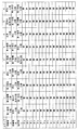
具体的には、図7に示したようなタイミングで、各吸着塔A′,B′,C′,D′において各工程(ステップ1〜12)が行われる。各ステップにおいては、各自動弁a′〜u′の開閉状態は、図7に示したように選択されており、各ステップにおけるPSA分離装置X′のガス流れを模式的に表せば、図8(a)〜(l)に示したようなものとなっている。
【0060】
ステップ1においては、図7に示したように吸着塔A′では第1吸着工程、吸着塔B′では第2洗浄工程、吸着塔C′では第2脱着工程、吸着塔D′では第1減圧工程が行われており、図8(a)に示したようなガス流れ状態とされている。
【0061】
図6および図8(a)に示したように、吸着塔A′には、混合ガス用配管1′および自動弁a′を介して混合ガスが導入される。吸着塔A′では、吸着剤により不要ガスが除去されて製品ガスが塔外に排出される。製品ガスは、自動弁k′および製品ガス用配管2′を介して回収される。
【0062】
吸着塔B′には、自動弁s′、塔内ガス回収用配管3′、流量調整弁7′、ガス導入用配管4′、および自動弁l′を介して、吸着塔D′から排出された塔内ガス(洗浄ガス)が導入される。吸着塔D′は、先に吸着工程を行っているのに対して吸着塔B′は先に(第3)脱着工程を行っていたから(ステップ12(図7、図8(l)参照))、吸着塔D′の塔内のほうが吸着塔B′の塔内よりも高圧とされている。そのため、吸着塔D′の塔内ガスを吸着塔B′に導入することにより、吸着塔D′の塔内が減圧され、吸着塔B′からは塔内に残留するガスが排出される。このガスは、自動弁d′およびパージガス用配管6′を介して回収される。
【0063】
吸着塔D′から吸着塔B′に導入する塔内ガスの量は、常温・大気圧に換算して、吸着塔B′における吸着剤の充填容積の2〜5倍の範囲に流量調整弁7′により調整される。
【0064】
一方、吸着塔C′では、ステップ12に引き続き脱着工程が行われている。ステップ11においては塔内が減圧されているとともに、ステップ1では図7に示したようにステップ12と同様にして自動弁e′,o′,p′,q′が閉鎖され、自動弁f′が開放状態とされている。そのため、吸着塔C′の内部では吸着剤から不要ガスが脱着し、これが吸着塔C′内のガスとともに塔外に排出される。
この脱着ガスは、自動弁f′およびパージガス用配管6′を介して回収される。
【0065】
ステップ2においては、図7に示したように吸着塔A′では第2吸着工程、吸着塔B′は待機工程、吸着塔C′では第1洗浄工程、吸着塔D′では第2減圧工程が行われており、図8(b)に示したようなガス流れ状態とされている。
【0066】
図6および図8(b)に示したように、吸着塔A′では、ステップ1と同様に吸着工程が行われている。
【0067】
吸着塔B′は、自動弁c′,d′,l′,m′,n′が閉鎖状態とされて、待機工程とされている。
【0068】
吸着塔C′には、自動弁s′、塔内ガス回収用配管3′、流量調整弁7′、ガス導入用配管4′、および自動弁o′を介して、吸着塔D′から排出された塔内ガス(洗浄ガス)が導入される。吸着塔D′は、ステップ1において第1減圧工程を行っているが、ステップ1において先に(第2)脱着工程を行っていた吸着塔C′に比べると、塔内の圧力は高い。そのため、吸着塔D′の塔内ガスを吸着塔C′に導入することにより、吸着塔D′の塔内がさらに減圧されると同時に、吸着塔C′からは塔内に残留するガスが排出される。このガスは、自動弁f′およびパージガス用配管6′を介して回収される。
【0069】
吸着塔D′から吸着塔C′に導入する塔内ガスの量は、常温・大気圧に換算して、吸着塔C′における吸着剤の充填容積の1〜3倍の範囲に流量調整弁7′により調整される。
【0070】
ステップ3においては、図7に示したように吸着塔A′では第3吸着工程、吸着塔B′は昇圧工程、吸着塔C′では第3脱着工程、吸着塔D′では第1脱着工程が行われており、図8(c)に示したようなガス流れ状態とされている。
【0071】
図6および図8(c)に示したように、吸着塔A′には、ステップ1と同様にして混合ガスが導入され、製品ガスが塔外に排出される。製品ガスは、ステップ1と同様にして回収されるが、その一部が製品パージ用配管5′、自動弁u′、流量調整弁8′、ガス導入用配管4′、および自動弁l′を介して吸着塔B′に導入され、吸着塔B′の塔内の昇圧が行われる。
【0072】
吸着塔C′では、ステップ1の場合と同様にして吸着剤からの不要ガスの脱着が行われており、脱着ガスが自動弁f′およびパージガス用配管6′を介して回収される。
【0073】
吸着塔D′は、ステップ2においては塔内が減圧されているとともに、図7に示したように自動弁g′,r′,s′,t′が閉鎖され、自動弁h′が開放状態とされている。そのため、吸着塔D′の内部では吸着剤から不要ガスが脱着し、これが吸着塔D′内のガスとともに塔外に排出される。この脱着ガスは、自動弁h′およびパージガス用配管6′を介して回収される。
【0074】
ステップ4〜6においては、図7および図8(d)〜(f)に示したように、吸着塔A′ではステップ1〜3における吸着塔D′と同様にして第1減圧工程、第2減圧工程、および第1脱着工程が行われ、吸着塔B′ではステップ1〜3における吸着塔A′と同様にして第1吸着工程、第2吸着工程、および第3吸着工程が行われ、吸着塔C′ではステップ1〜3における吸着塔B′と同様にして第2洗浄工程、待機工程および昇圧工程が行われ、吸着塔D′ではステップ1〜3における吸着塔C′と同様にして第2脱着工程、第1洗浄工程、および第3脱着工程が行われる。
【0075】
ステップ7〜9においては、図7および図8(g)〜(i)に示したように、吸着塔A′ではステップ1〜3における吸着塔C′と同様にして第2脱着工程、第1洗浄工程、および第3脱着工程が行われ、吸着塔B′ではステップ1〜3における吸着塔D′と同様にして第1減圧工程、第2減圧工程、および第1脱着工程が行われ、吸着塔C′ではステップ1〜3における吸着塔A′と同様にして第1吸着工程、第2吸着工程、および第3吸着工程が行われ、吸着塔D′ではステップ1〜3における吸着塔B′と同様にして第2洗浄工程、待機工程、および昇圧工程が行われる。
【0076】
ステップ10〜12においては、図7および図8(j)〜(l)に示したように、吸着塔A′ではステップ1〜3における吸着塔B′と同様にして第2洗浄工程、待機工程、および昇圧工程が行われ、吸着塔B′ではステップ1〜3における吸着塔C′と同様にして第2脱着工程、第1洗浄工程、および第3脱着工程が行われ、吸着塔C′ではステップ1〜3における吸着塔D′と同様にして第1減圧工程、第2減圧工程、および第1脱着工程が行われ、吸着塔D′ではステップ1〜3における吸着塔A′と同様にして第1吸着工程、第2吸着工程、および第3吸着工程が行われる。
【0077】
なお、各吸着塔A′,B′,C′,D′での第1〜第3吸着工程における最終圧力は、0.1〜3.5MPa(ゲージ圧)の範囲とされ、各吸着塔A′,B′,C′,D′での脱着工程における最低圧力は、0.05MPa(ゲージ圧)〜大気圧の範囲とされる。
【0078】
そして、以上に説明したステップ1〜12を各吸着塔A′,B′,C′,D′において繰り返し行うことにより、混合ガスから不要ガスが除去され、水素ガス濃度の高い製品ガスが連続的に得られる。
【0079】
図6ないし図8を参照して説明した分離方法では、ステップ1および2から分かるように(図8(a)および(b)参照)、吸着工程を終了した吸着塔D′からは、第1減圧工程(ステップ1)として吸着塔B′に塔内ガスが導入され、第2減圧工程(ステップ2)として吸着塔C′に塔内ガスが導入される。つまり、1つの吸着塔D′の塔内ガスが2つの吸着塔B′,C′の洗浄に使用される。このとき、第1および第2減圧工程では、製品ガス出口側から塔内ガスが排出されるが、吸着工程終了後の吸着塔D′では、製品ガス出口の近いほうが不要ガスの濃度が低い。そのため、吸着塔D′の第1減圧工程により吸着塔B′に供給される塔内ガスのほうが、吸着塔D′の第2減圧工程により吸着塔C′に供給される塔内ガスのよりも不要ガス濃度は低い。もちろん、2度に分けて塔内ガスを排出した場合には、先に排出される塔内ガスのほうが後に排出される塔内ガスよりも圧力は高い。
【0080】
一方、ステップ1〜4から分かるように(図8(a)〜(d)参照)、吸着塔C′に着目すれば、第2脱着工程、第1洗浄工程、第3脱着工程、および第2洗浄工程といったように、脱着工程と洗浄工程とが繰り返し行われる。
【0081】
吸着塔C′に着目すれば、塔内を減圧して脱着した後は、圧力が低く不要ガス濃度の相対的に高い洗浄ガスが導入される。第2減圧工程により排出される塔内ガスといえども、第2脱着工程終了後の吸着塔C′内に残留するガスよりも不要ガス濃度は低い。そのため、第1洗浄工程においては、洗浄ガスの導入により吸着塔C′に残留するガスが排出され、塔内での不要ガス濃度が第1洗浄工程前よりは低減される。その結果、塔内における不要ガスの分圧が小さくなって吸着剤からの不要ガスの脱着が助長され、次いで行う第3脱着工程において、吸着剤の再生が確実ならしめられる。そして、吸着塔C′内に残留するガスは、第1減圧工程を行っている吸着塔A′からの塔内ガスの導入により排出される。この塔内ガスは、先にも触れたように不要ガス濃度が低いものであるから、吸着塔C′内の不要ガス濃度がさらに低減されるとともに、吸着剤に吸着した不要ガスをより多く脱着することにより再生効率が高められる。
【0082】
なお、第1および第2洗浄工程の後に、図8(b),(e),(h),(k)に破線で示したように、製品ガスのよる追加の洗浄工程を設けてもよい。この場合のガス流れ状態は、図7におけるステップ2,5,8,11に括弧書きで示したように、一部の自動弁の開閉状態を変更することにより達成される。
【0083】
追加の洗浄工程において導入される洗浄ガスは、製品ガスであり、第2洗浄工程において導入される他の吸着塔の塔内ガスよりも不要ガス濃度は低い。そのため、追加の洗浄工程を設けることにより、さらに徹底的に塔内の洗浄を行うことができるようになる。また、先に第1および第2洗浄工程を行っていれば、追加の洗浄工程において必要とされる洗浄ガス(製品ガス)の量は少なくて済む結果、吸着塔の外部に排出される水素ガスの量が少なくなり、回収できる水素ガスの量が多くなる。
【0084】
【実施例】
次に、本発明の有用性を実施例および比較例により説明する。
【0085】
〔実施例1〕
本実施例では、吸着塔を3つ有する図1に示したPSA分離装置Xを用いて、図2に示す各工程からなる分離方法(本発明の第1の実施の形態に係る方法)により、以下に示す条件下で混合ガスから水素ガスを分離した。その結果を表1に示した。
【0086】
吸着塔としては、直径が50mmの円筒状のものを用い、その内部には吸着剤としてのゼオライトモレキュラーシーブ(Ca5A型)とカーボンモレキュラーシーブとを1:1.3の体積割合で合計2.935リットル充填した。混合ガスとしては、容積基準で、水素ガス77.77%、炭酸ガス19.62%、一酸化炭素1%、窒素ガス0.0008%、およびメタンガス1.61%を含むものを使用した。この混合ガスは、851Nリットル/hrで供給した。吸着工程における最高圧力は、850kPa(ゲージ圧)、脱着工程における最低圧力は、6kPa(ゲージ圧)、減圧工程における最終圧力は、350kPa(ゲージ圧)とした。洗浄工程を行っている吸着塔に対して、吸着工程が終了した他の吸着塔から導入された洗浄ガスの量は、吸着剤の充填容積の約5倍であった。
【0087】
〔実施例2〕
本実施例では、減圧工程における最終圧力を650kPa(ゲージ圧)とし、洗浄工程において導入された洗浄ガスの量は吸着剤の充填容積の約2倍であった以外は実施例1と同様にして混合ガスから水素ガスの分離を行った。その結果を表1に示した。
【0088】
〔実施例3〕
本実施例では、減圧工程における最終圧力を450kPa(ゲージ圧)とし、洗浄工程において導入された洗浄ガスの量は吸着剤の充填容積は約4倍であった以外は実施例1と同様にして混合ガスから水素ガスの分離を行った。その結果を表1に示した。
【0089】
〔実施例4〕
本実施例では、減圧工程における最終圧力を250kPa(ゲージ圧)とし、洗浄工程において導入された洗浄ガスの量は吸着剤の充填容積の約6倍であった以外は実施例1と同様にして混合ガスから水素ガスの分離を行った。その結果を表1に示した。
【0090】
〔実施例5〕
本実施例では、減圧工程における最終圧力を150kPa(ゲージ圧)とし、洗浄工程において導入された洗浄ガスの量は吸着剤の充填容積の約7倍であった以外は実施例1と同様にして混合ガスから水素ガスの分離を行った。その結果を表1に示した。
【0091】
〔比較例1〕
本比較例では、図1に示すPSA分離装置Xを用いて、図9に示す各工程からなる分離方法(均圧工程を有する従来の分離方法)により、混合ガスから水素ガスの分離を行った。洗浄ガスの由来(種類)以外の条件は、実施例1と同様とした。その結果を表1に示す。
【0092】
【表1】

表1から明らかなように、洗浄ガスとして吸着工程を終了した吸着塔の塔内ガスを使用し、その洗浄ガス量を吸着剤の充填容積の2〜7倍の範囲とした場合には(実施例1〜5)、回収される製品ガスの量および水素ガス収率に優れている。
【0094】
また、洗浄ガスの量を実施例1〜5における範囲内にした場合には、吸着工程を終了した吸着塔内の塔内ガスにより他の吸着塔の昇圧を行うとともに、脱着工程を終了した吸着塔の洗浄を製品ガスのみにより行う場合(比較例1)に比べて、良好な結果が得られている。
【0095】
【発明の効果】
以上に説明したように、本発明では、PSA法による水素ガスの分離において、吸着剤の再生効率を高めるとともに、得られる製品ガス中の水素ガスの純度および水素ガスの収率を高めることができる。
【図面の簡単な説明】
【図1】PSA法を実施するための3塔式のPSA分離装置の概略構成図である。
【図2】本発明の第1の実施の形態に係る分離方法の各ステップにおいて、各吸着塔で行われている工程およびそのときの弁の開閉状態を示す表である。
【図3】第1の実施形態に係る分離方法の各ステップにおけるPSA分離装置のガス流れ状態を示す図である。
【図4】本発明の第2の実施の形態に係る分離方法の各ステップにおいて、各吸着塔で行われている工程およびそのときの弁の開閉状態を示す表である。
【図5】第2の実施形態に係る分離方法における追加のステップでのPSA分離装置のガス流れ状態を示す図である。
【図6】本発明の第3の実施の形態に係る分離方法を実施するための4塔式のPSA分離装置の概略構成図である。
【図7】第3の実施の形態に係る分離方法の各ステップにおいて、各吸着塔で行われている工程およびそのときの弁の開閉状態を示す表である。
【図8】第3の実施形態に係る分離方法の各ステップにおけるPSA分離装置のガス流れ状態を示す図である。
【図9】従来の分離方法における各ステップにおいて、各吸着塔で行われている工程およびそのときの弁の開閉状態を示す表である。
【図10】従来の分離方法の各ステップにおけるPSA分離装置のガス流れ状態を示す図である。
【符号の説明】
X,X′ PSA分離装置
A,B,C,A′,B′,C′,D′ 吸着塔
1,1′ 混合ガス用配管
2,2′ 製品ガス用配管
3,3′ 塔内ガス回収用配管
4,4′ ガス導入用配管
5,5′ 製品パージ用配管
6,6′ パージガス用配管
7,8,7′,8′ 流量調整弁
a〜p,a′〜u′ 自動弁[0001]
BACKGROUND OF THE INVENTION
The present invention relates to a method for separating hydrogen gas by removing unnecessary gas from a mixed gas by using a pressure fluctuation adsorption (PSA) method.
[0002]
[Prior art]
As a method for separating a target gas such as hydrogen gas from a mixed gas, there is a PSA method. This PSA method is performed by providing 2 to 4 adsorption towers filled with an adsorbent and repeating a cycle including an adsorption process, a depressurization process, a desorption process, and a pressurization process in each adsorption tower. In the PSA method, various improvements have been made from the viewpoint of the purity and yield of the resulting hydrogen gas (for example, Japanese Patent Publication No. Sho 62-38014, Japanese Patent Publication No. 7-4498, Japanese Patent Publication No. Hei 8-10551). .
[0003]
As an example, a product gas from an adsorption tower that is performing an adsorption process is supplied to an adsorption tower that has completed the desorption process, and the gas remaining in the adsorption tower is discharged after the desorption process to wash the adsorption tower. is there. As another example, by equalizing the pressure between one adsorption tower at the high pressure after completion of the adsorption process and the other adsorption tower at the low pressure after completion of the desorption process or washing process Some adsorption towers perform pressure reduction in the adsorption tower, while other adsorption towers perform pressure increase.
[0004]
The PSA method for performing such cleaning and pressure equalization can be performed using, for example, the PSA separation apparatus X shown in FIG. The PSA separation apparatus X shown in this figure has three adsorption towers A, B, C, a mixed
[0005]
In
[0006]
In
[0007]
Product gas is introduced into the adsorption tower C through the
[0008]
In
[0009]
In
[0010]
In steps 7-9, as shown in FIG. 9 and FIGS. 10 (g)-(i), in the adsorption tower A, as in the adsorption tower B in steps 1-3, the first boosting process and the second boosting process. In the adsorption tower B, the desorption process, the washing process, and the second pressure equalization (pressure increase) process are performed in the same manner as the adsorption tower C in
[0011]
And by repeating steps 1-9 demonstrated above in each adsorption tower A, B, and C, unnecessary gas is removed from mixed gas and product gas with a high hydrogen gas concentration is obtained continuously.
[0012]
In the PSA method described above, since the product gas from the adsorption towers A, B, and C that are performing the adsorption process on the adsorption towers C, A, and B after the desorption process is introduced, the adsorption towers C, The unnecessary gas components in the towers A and B are effectively discharged, and the regeneration efficiency of the adsorbent is increased. In the PSA method, pressure equalization is achieved between the adsorption towers A, B, C after the adsorption process and the adsorption towers C, A, B after the washing process. In the adsorption towers A, B, and C after the adsorption process is completed, it is necessary to discharge the gas in the tower and reduce the pressure in the tower in order to regenerate the adsorbent, so the gas in the tower is washed. If the process is completed and then introduced into the towers of the adsorption towers C, A and B where the adsorption process is performed, the pressure during the adsorption process can be used effectively. In addition, since the gas remaining in the tower after the adsorption step has a high hydrogen gas concentration and contains a large amount of hydrogen gas, if the gas remaining in the adsorption tower A, B, C is transferred to another adsorption tower, Can be recovered as product gas. Therefore, performing pressure equalization among the adsorption towers A, B, and C seems to be useful from the viewpoint of effective use of pressure and increasing the recovery rate of hydrogen gas.
[0013]
[Problems to be solved by the invention]
However, even if a cleaning process is used in which the product gas is used as the cleaning gas and the amount of the cleaning gas is converted to room temperature and atmospheric pressure to make it smaller than the adsorbent filling volume, the yield of hydrogen gas is sufficiently improved. However, there is still room for improvement in the PSA method.
[0014]
In addition, the equalization of pressure between the adsorption towers A, B, and C provides the above-mentioned advantage, but unnecessary gas components are simultaneously introduced into the adsorption towers A, B, and C to be pressurized while hydrogen gas is used. End up. Therefore, in spite of the regeneration of the adsorbent in the desorption process, unnecessary gas in the pressure equalizing gas is adsorbed before the adsorption process, and the adsorbable capacity of the adsorbent is substantially reduced. Occurs.
[0015]
The present invention has been conceived under such circumstances, and in the separation of hydrogen gas by the PSA method, while improving the regeneration efficiency of the adsorbent, the purity of the hydrogen gas in the product gas obtained and The problem is to increase the yield of hydrogen gas.
[0016]
[Means for Solving the Problems]
In order to solve the above problems, the present invention takes the following technical means. That is, the hydrogen gas separation method provided by the present invention is a method of separating hydrogen gas from a mixed gas using a plurality of adsorption towers filled with an adsorbent, and the unnecessary gas in the mixed gas is adsorbed. Adsorption process that discharges product gas with a high hydrogen gas concentration, a depressurization process that lowers the pressure in the adsorption tower, a desorption process that desorbs unnecessary gas adsorbed on the adsorbent, and a cleaning gas in the adsorption tower In the hydrogen gas separation method in which a cycle including a cleaning step for introducing gas and discharging a gas remaining in the tower and a pressure increasing step for increasing the pressure in the adsorption tower is repeated, the pressure reducing step includes a target to be cleaned. A step of discharging a tower gas as a cleaning gas to be introduced into one adsorption tower, and the amount of the tower gas introduced into the one adsorption tower is converted to normal temperature and atmospheric pressure. The adsorption tower It is characterized in that 2 to 7 times the filling volume of the adsorbent that.
[0017]
According to this separation method, when the amount of the cleaning gas in the above-described range is introduced into one adsorption tower to be cleaned, at least a part of the cleaning gas introduced into the adsorption tower in the cleaning step is external to one adsorption tower. To be discharged. As the cleaning gas, the gas in the tower of the other adsorption tower that is performing the depressurization process is used. However, since the other adsorption tower has already performed the adsorption process, the unnecessary gas in the gas in the tower of the other adsorption tower is used. The concentration of is less than the concentration of unnecessary gas in the gas remaining in one adsorption tower that has been previously desorbed.
[0018]
Therefore, if the cleaning gas is introduced into one adsorption tower until at least a part of the cleaning gas is discharged from the adsorption tower, the gas in one adsorption tower is effectively caused by a gas having a low unnecessary gas concentration. Will be replaced. As a result, during the cleaning process, the concentration or partial pressure of unnecessary gas in one adsorption tower is reduced, desorption of unnecessary gas from the adsorbent is promoted, and a larger amount of unnecessary gas is desorbed from the adsorbent. At the same time, the concentration of unnecessary gas in one adsorption tower can be kept small even after the end of the cleaning process.
[0019]
Even if the adsorption process is performed in one adsorption tower after the cleaning process is completed, the concentration of unnecessary gas in the gas remaining in the tower is low, so the amount of unnecessary gas mixed in the product gas is extremely small. . As a result, the purity of the recovered product gas can be increased.
[0020]
In a preferred embodiment, the cleaning step includes at least a first cleaning step and a second cleaning step, and the decompression step includes at least a first decompression step and a second decompression step. In one adsorption tower, the first washing step is performed prior to the second washing step and the second washing step is performed while the adsorption step is finished and the next adsorption step is carried out. Prior to the depressurization step, the first depressurization step is performed, and the first depressurization step and the second depressurization step are performed by discharging the gas in the tower from the product gas outlet, and the first depressurization process is performed in the first adsorption tower. The first cleaning step is performed by introducing the column gas discharged in the second depressurization step of another adsorption tower as a cleaning gas from the product gas outlet, and the second cleaning step in one adsorption tower is performed as follows. It carried out by introducing the other of the discharged tower gas in the first depressurization step of the adsorption tower as cleaning gas from the product gas outlet.
[0021]
According to such a separation method, if attention is paid to one adsorption tower, at least twice washing is performed, and the first washing (first washing process) is discharged at the time of the second decompression process of the other adsorption tower. In the second cleaning (second cleaning step), the column gas discharged in the first depressurization step of another adsorption tower is introduced.
[0022]
In other adsorption towers that have completed the adsorption process, the closer to the product gas outlet, the lower the concentration of unnecessary gas. Therefore, if the product gas outlet of the other adsorption tower is opened and decompressed, As the inner gas is discharged, the concentration of unnecessary gas in the gas increases with time. Therefore, the unnecessary gas concentration in the tower gas discharged in the second decompression step is higher than the unnecessary gas concentration in the tower gas discharged in the first decompression step.
[0023]
Therefore, in one adsorption tower, after the gas in the other adsorption tower having a relatively high unnecessary gas concentration is introduced in the first cleaning step, the other unnecessary gas concentration is further reduced in the second cleaning step. The gas inside the adsorption tower is introduced. As a result, as a whole cleaning process, preliminary cleaning is performed in the first cleaning process, and full-scale cleaning is performed in the second cleaning process. Therefore, after completion of the first and second cleaning steps, the concentration of unnecessary gas in one adsorption tower is remarkably reduced, and even if the adsorption step is performed after the washing step, it is unnecessary to remain in the adsorption tower after the washing step. A decrease in product gas purity due to the gas is suppressed.
[0024]
In a preferred embodiment, the cleaning step includes an additional cleaning step of introducing a product gas as a cleaning gas from the adsorption tower performing the adsorption step. In this case, while the adsorption process is completed first and the next adsorption process is performed, the decompression process, the desorption process, the first washing process, the desorption process, the second washing process, and the additional washing process are performed in this order. Is called.
[0025]
According to such a separation method, the interior of the adsorption tower is finally cleaned with the product gas, so that the amount of unnecessary gas remaining in the adsorption tower after the cleaning step is further reduced, and the purity of the recovered product gas is increased. Can be increased. In addition, since cleaning with the gas in the other adsorption tower is performed before the cleaning with the product gas, the amount of the product gas required in the additional cleaning process, and hence the exhaust gas is discharged from the adsorption tower in the cleaning process. The amount of product gas produced can be reduced and the hydrogen gas recovery rate can be increased.
[0026]
The maximum pressure in the adsorption process is, for example, in the range of 0.1 to 3.5 MPa (gauge pressure), and the minimum pressure in the desorption process is, for example, in the range of 0.05 MPa (gauge pressure) to atmospheric pressure.
[0027]
The present invention can be suitably employed when separating hydrogen gas from a mixed gas containing carbon dioxide gas as an unnecessary gas.
[0028]
Industrially, hydrogen gas is produced by removing unnecessary gas from a mixed gas containing hydrogen gas and carbon dioxide gas obtained by steam reforming a hydrocarbon compound (typically methanol or natural gas). can get. Therefore, when industrially obtaining hydrogen gas, it is necessary to remove the carbon dioxide gas from the mixed gas to increase the hydrogen gas concentration, and in this case, the present invention is suitably employed. In addition, carbon dioxide has a characteristic that it has a strong adsorptive power to the adsorbent, and unless the carbon dioxide is removed effectively, the removal efficiency of other unnecessary gas components, such as methane, is deteriorated and the hydrogen gas is absorbed. Since the problem that the rate falls may also occur, the separation method of the present invention, which is excellent in the regeneration efficiency of the adsorbent, is exactly suitable for the separation step in the industrial hydrogen gas production process.
[0029]
DETAILED DESCRIPTION OF THE INVENTION
Hereinafter, preferred embodiments of the present invention will be specifically described with reference to the drawings.
[0030]
The hydrogen gas separation method according to the first embodiment of the present invention can be performed using, for example, the PSA separation apparatus shown in FIG. The PSA separation apparatus X shown in this figure has three adsorption towers A, B, C, a
[0031]
Each adsorption tower A, B, C is filled with an adsorbent. As the adsorbent, when removing carbon dioxide or methane gas as unnecessary gas, for example, carbon-based one is used. When removing carbon monoxide or nitrogen gas as unnecessary gas, for example, zeolite-based one is not necessary. When removing water vapor as a gas, for example, alumina is used. Of course, two or more adsorbents exemplified may be used in combination, and adsorbents other than those exemplified may be used.
[0032]
The
[0033]
Specifically, each process (
[0034]
In
[0035]
As shown in FIGS. 1 and 3A, the mixed gas is introduced into the adsorption tower A through the
[0036]
In the adsorption tower B, the gas in the tower (cleaning gas) discharged from the adsorption tower C through the automatic valve n, the
[0037]
The amount of gas in the column introduced from the adsorption tower C to the adsorption tower B is adjusted by the flow
[0038]
The maximum pressure in the adsorption tower A (adsorption process) is in the range of 0.1 to 3.5 MPa (gauge pressure).
[0039]
In
[0040]
As shown in FIGS. 1 and 3B, the mixed gas is introduced into the adsorption tower A in the same manner as in
[0041]
On the other hand, in the adsorption tower C, as shown in FIG. 2, the inside of the tower is depressurized in
[0042]
The minimum pressure in the adsorption tower C (desorption step) is in the range of 0.05 MPa (gauge pressure) to atmospheric pressure.
[0043]
In
[0044]
In
[0045]
In
[0046]
And by repeating steps 1-6 demonstrated above in each adsorption tower A, B, C, an unnecessary gas is removed from mixed gas and product gas with a high hydrogen gas concentration is obtained continuously.
[0047]
Next, a hydrogen gas separation method according to a second embodiment of the present invention will be described with reference to FIGS.
[0048]
In the separation method according to the present embodiment, an additional cleaning step using a product gas is added as shown in FIG. Specifically, Steps 1 to 6 are performed in the same manner as in the first embodiment of the present invention, but Steps 1 ', 3', and 5 'as additional cleaning steps after
[0049]
In the additional cleaning process, the open / close state of each of the automatic valves ap is selected as shown in FIG. 4, and the gas flows as shown in FIGS. 5 (a) to 5 (c).
[0050]
In
[0051]
In the adsorption tower C, the first desorption process is performed in the same manner as in
[0052]
The amount of the cleaning gas introduced into the adsorption tower B in the additional cleaning step is adjusted by the flow
[0053]
In
[0054]
In step 5 ', as shown in FIG. 4 and FIG. 5 (c), an additional cleaning step is performed in the adsorption tower A in the same manner as the adsorption tower B in step 1'. In the adsorption tower B, the adsorption tower in step 1 'is performed. As in C, the first desorption process is performed, and in the adsorption tower C, the second adsorption process is performed in the same manner as the adsorption tower A in
[0055]
As in the separation method according to the present embodiment, the adsorption process is performed after the cleaning process (
[0056]
Next, a hydrogen gas separation method according to the third embodiment of the present invention will be described with reference to FIGS.
[0057]
The separation method according to the present embodiment is performed using a four-column PSA separation apparatus X ′ shown in FIG. The basic configuration of the PSA separator X ′ is the same as that of the PSA separator X described above with reference to FIG. However, the PSA separation apparatus X ′ of FIG. 6 has a slight difference in the number of automatic valves a ′ to u ′, etc. due to having four adsorption columns A ′, B ′, C ′, D ′. There is.
[0058]
In the separation method according to the present embodiment, the adsorption process, the depressurization process, and the desorption process are performed in each of the adsorption towers A ′, B ′, C ′, and D ′ by selecting the open / close states of the automatic valves a ′ to u ′. A cleaning process and a pressure increasing process are performed.
[0059]
Specifically, each process (
[0060]
In
[0061]
As shown in FIGS. 6 and 8 (a), the mixed gas is introduced into the adsorption tower A 'through the mixed gas pipe 1' and the automatic valve a '. In the adsorption tower A ′, unnecessary gas is removed by the adsorbent and the product gas is discharged outside the tower. The product gas is recovered through the automatic valve k ′ and the
[0062]
The adsorption tower B ′ is discharged from the adsorption tower D ′ via the automatic valve s ′, the
[0063]
The amount of gas in the column introduced from the adsorption tower D ′ to the adsorption tower B ′ is in the range of 2 to 5 times the packed volume of the adsorbent in the adsorption tower B ′ in terms of normal temperature and atmospheric pressure. It is adjusted by '.
[0064]
On the other hand, in the adsorption tower C ′, the desorption process is performed following
The desorption gas is recovered through the automatic valve f ′ and the
[0065]
In
[0066]
As shown in FIG. 6 and FIG. 8B, the adsorption step is performed in the adsorption tower A ′ in the same manner as in
[0067]
The adsorption tower B ′ is in a standby process with the automatic valves c ′, d ′, l ′, m ′, n ′ being closed.
[0068]
The adsorption tower C ′ is discharged from the adsorption tower D ′ via an automatic valve s ′, a
[0069]
The amount of gas in the column introduced from the adsorption tower D ′ to the adsorption tower C ′ is in the range of 1 to 3 times the packed volume of the adsorbent in the adsorption tower C ′ in terms of normal temperature and atmospheric pressure. It is adjusted by '.
[0070]
In
[0071]
As shown in FIG. 6 and FIG. 8 (c), the mixed gas is introduced into the adsorption tower A ′ in the same manner as in
[0072]
In the adsorption tower C ′, the unnecessary gas is desorbed from the adsorbent in the same manner as in
[0073]
In
[0074]
In
[0075]
In
[0076]
In
[0077]
The final pressure in the first to third adsorption steps in each adsorption tower A ′, B ′, C ′, D ′ is in the range of 0.1 to 3.5 MPa (gauge pressure). The minimum pressure in the desorption process at ′, B ′, C ′, D ′ is in the range of 0.05 MPa (gauge pressure) to atmospheric pressure.
[0078]
Then, by repeating
[0079]
In the separation method described with reference to FIGS. 6 to 8, as can be seen from
[0080]
On the other hand, as can be seen from
[0081]
Focusing on the adsorption tower C ′, after depressurizing and desorbing the inside of the tower, a cleaning gas having a low pressure and a relatively high unnecessary gas concentration is introduced. Even in the tower gas discharged in the second depressurization process, the concentration of unnecessary gas is lower than the gas remaining in the adsorption tower C ′ after the completion of the second desorption process. Therefore, in the first cleaning process, the gas remaining in the adsorption tower C ′ is discharged by introducing the cleaning gas, and the concentration of unnecessary gas in the tower is reduced as compared with that before the first cleaning process. As a result, the partial pressure of the unnecessary gas in the tower is reduced, and the desorption of the unnecessary gas from the adsorbent is promoted. In the third desorption step to be performed next, the regeneration of the adsorbent is ensured. And the gas which remains in adsorption tower C 'is discharged | emitted by introduction of the gas in a tower from adsorption tower A' which is performing the 1st pressure reduction process. As mentioned above, since the unnecessary gas concentration in the tower is low, the unnecessary gas concentration in the adsorption tower C ′ is further reduced and more unnecessary gas adsorbed on the adsorbent is desorbed. By doing so, the reproduction efficiency is improved.
[0082]
After the first and second cleaning steps, an additional cleaning step using product gas may be provided as shown by broken lines in FIGS. 8B, 8E, 8H, and 8K. . The gas flow state in this case is achieved by changing the open / close state of some automatic valves, as shown in parentheses in
[0083]
The cleaning gas introduced in the additional cleaning step is a product gas, and the unnecessary gas concentration is lower than the gas in the other adsorption tower introduced in the second cleaning step. Therefore, by providing an additional cleaning step, the inside of the tower can be cleaned more thoroughly. In addition, if the first and second cleaning steps have been performed first, the amount of cleaning gas (product gas) required in the additional cleaning step can be reduced. As a result, hydrogen gas discharged to the outside of the adsorption tower The amount of hydrogen gas is reduced, and the amount of hydrogen gas that can be recovered is increased.
[0084]
【Example】
Next, the usefulness of the present invention will be described with reference to examples and comparative examples.
[0085]
[Example 1]
In this example, by using the PSA separation apparatus X shown in FIG. 1 having three adsorption towers, the separation method (method according to the first embodiment of the present invention) consisting of each step shown in FIG. Hydrogen gas was separated from the mixed gas under the conditions shown below. The results are shown in Table 1.
[0086]
As the adsorption tower, a cylindrical one having a diameter of 50 mm is used, and in the inside thereof, a zeolite molecular sieve (Ca5A type) and a carbon molecular sieve as adsorbents in a volume ratio of 1: 1.3 are total 2.935. Filled with liters. As the mixed gas, a gas containing 77.77% hydrogen gas, 19.62% carbon dioxide, 1% carbon monoxide, 0.0008% nitrogen gas, and 1.61% methane gas on a volume basis was used. This mixed gas was supplied at 851 Nl / hr. The maximum pressure in the adsorption process was 850 kPa (gauge pressure), the minimum pressure in the desorption process was 6 kPa (gauge pressure), and the final pressure in the decompression process was 350 kPa (gauge pressure). The amount of the cleaning gas introduced from the other adsorption tower after the adsorption process was about 5 times the packed volume of the adsorbent with respect to the adsorption tower performing the washing process.
[0087]
[Example 2]
In this example, the final pressure in the depressurization step was 650 kPa (gauge pressure), and the amount of the cleaning gas introduced in the cleaning step was the same as in Example 1 except that it was about twice the filling volume of the adsorbent. Hydrogen gas was separated from the mixed gas. The results are shown in Table 1.
[0088]
Example 3
In this example, the final pressure in the depressurization step was 450 kPa (gauge pressure), and the amount of the cleaning gas introduced in the cleaning step was the same as in Example 1 except that the adsorbent filling volume was about four times. Hydrogen gas was separated from the mixed gas. The results are shown in Table 1.
[0089]
Example 4
In this example, the final pressure in the depressurization step was 250 kPa (gauge pressure), and the amount of the cleaning gas introduced in the cleaning step was the same as in Example 1 except that it was about 6 times the filling volume of the adsorbent. Hydrogen gas was separated from the mixed gas. The results are shown in Table 1.
[0090]
Example 5
In this example, the final pressure in the depressurization step was 150 kPa (gauge pressure), and the amount of the cleaning gas introduced in the cleaning step was the same as in Example 1 except that it was about 7 times the filling volume of the adsorbent. Hydrogen gas was separated from the mixed gas. The results are shown in Table 1.
[0091]
[Comparative Example 1]
In this comparative example, hydrogen gas was separated from the mixed gas using the PSA separation apparatus X shown in FIG. 1 by the separation method (conventional separation method having a pressure equalization step) consisting of the steps shown in FIG. . Conditions other than the origin (kind) of the cleaning gas were the same as in Example 1. The results are shown in Table 1.
[0092]
[Table 1]
As is apparent from Table 1, when the gas in the tower of the adsorption tower that has completed the adsorption process is used as the cleaning gas, and the amount of the cleaning gas is in the range of 2 to 7 times the packing volume of the adsorbent (implementation) Examples 1 to 5) are excellent in the amount of product gas recovered and the hydrogen gas yield.
[0094]
In addition, when the amount of the cleaning gas is within the range in Examples 1 to 5, while the pressure in the other adsorption tower is increased by the gas in the adsorption tower that has completed the adsorption process, the adsorption that has completed the desorption process. Compared with the case where the tower is cleaned only with the product gas (Comparative Example 1), good results are obtained.
[0095]
【The invention's effect】
As described above, in the present invention, in the separation of hydrogen gas by the PSA method, the regeneration efficiency of the adsorbent can be increased, and the purity of the hydrogen gas and the yield of hydrogen gas in the product gas obtained can be increased. .
[Brief description of the drawings]
FIG. 1 is a schematic configuration diagram of a three-column PSA separator for carrying out a PSA method.
FIG. 2 is a table showing steps performed in each adsorption tower and the valve open / closed state at that time in each step of the separation method according to the first embodiment of the present invention.
FIG. 3 is a diagram showing a gas flow state of the PSA separation device in each step of the separation method according to the first embodiment.
FIG. 4 is a table showing a process performed in each adsorption tower and a valve open / closed state at that time in each step of the separation method according to the second embodiment of the present invention.
FIG. 5 is a diagram showing a gas flow state of the PSA separation device at an additional step in the separation method according to the second embodiment.
FIG. 6 is a schematic configuration diagram of a 4-tower PSA separation apparatus for carrying out a separation method according to a third embodiment of the present invention.
FIG. 7 is a table showing steps performed in each adsorption tower and the valve open / closed state at that time in each step of the separation method according to the third embodiment.
FIG. 8 is a diagram showing a gas flow state of the PSA separation device in each step of the separation method according to the third embodiment.
FIG. 9 is a table showing the steps performed in each adsorption tower and the open / close state of the valves at that time in each step in the conventional separation method.
FIG. 10 is a diagram showing a gas flow state of the PSA separation device in each step of the conventional separation method.
[Explanation of symbols]
X, X 'PSA separator
A, B, C, A ', B', C ', D' adsorption tower
1,1 'Mixed gas piping
2,2 'Product gas piping
3,3 'Piping for gas recovery in the tower
4,4 'piping for gas introduction
5,5 'product purge piping
6,6 'Purge gas piping
7, 8, 7 ', 8' Flow control valve
a ~ p, a '~ u' Automatic valve
Claims (4)
上記減圧工程は、洗浄対象となる1つの吸着塔に対して導入すべき洗浄ガスとしての塔内ガスを排出する工程を含んでおり、
上記1つの吸着塔に導入される塔内ガスの量は、常温・大気圧に換算して、当該吸着塔における吸着剤の充填容積の2〜7倍であり、
上記洗浄工程は、第1洗浄工程と、第2洗浄工程と、を少なくとも含んでいるとともに、上記減圧工程は、第1減圧工程と、第2減圧工程と、を少なくとも含んでおり、1つの吸着塔においては、先に吸着工程が終了して次に吸着工程が行われる間では、上記第2洗浄工程に先んじて上記第1洗浄工程が行われるとともに、上記第2減圧工程に先んじて上記第1減圧工程が行われ、
上記第1減圧工程および上記第2減圧工程は、製品ガス出口から塔内ガスを排出することにより行われ、かつ、
1つの吸着塔における第1洗浄工程は、他の吸着塔の第2減圧工程において排出された塔内ガスを製品ガス出口から洗浄ガスとして導入することにより行われるとともに、1つの吸着塔における第2洗浄工程は、さらに他の吸着塔の第1減圧工程において排出された塔内ガスを製品ガス出口から洗浄ガスとして導入することにより行われる、水素ガスの分離方法。A method of separating hydrogen gas from a mixed gas using a plurality of adsorption towers filled with an adsorbent, and adsorbing unnecessary gas in the mixed gas with the adsorbent and discharging a product gas having a high hydrogen gas concentration A depressurization process for reducing the pressure in the adsorption tower, a desorption process for desorbing an unnecessary gas adsorbed on the adsorbent, and a cleaning process for introducing a cleaning gas into the adsorption tower and discharging the gas remaining in the tower And a hydrogen gas separation method in which a cycle including a pressure increasing step for increasing the pressure in the adsorption tower is repeated.
The depressurization step includes a step of discharging a tower gas as a cleaning gas to be introduced to one adsorption tower to be cleaned,
The amount of tower gas introduced into said one adsorption tower, in terms of normal temperature and atmospheric pressure, Ri 2-7 Baidea fill volume of the adsorbent in the adsorption tower,
The cleaning step includes at least a first cleaning step and a second cleaning step, and the decompression step includes at least a first decompression step and a second decompression step, and one adsorption In the tower, the first cleaning process is performed prior to the second cleaning process and the first cleaning process is performed prior to the second depressurizing process while the adsorption process is completed and the next adsorption process is performed. 1 decompression step is performed,
The first decompression step and the second decompression step are performed by discharging the gas in the tower from the product gas outlet, and
The first washing step in one adsorption tower is performed by introducing the tower gas discharged in the second decompression step of the other adsorption tower as a washing gas from the product gas outlet, and the second washing step in one adsorption tower. The cleaning step is a method for separating hydrogen gas , wherein the column gas discharged in the first depressurization step of another adsorption tower is introduced as a cleaning gas from the product gas outlet .
Priority Applications (11)
| Application Number | Priority Date | Filing Date | Title |
|---|---|---|---|
| JP2000392918A JP4611514B2 (en) | 2000-12-25 | 2000-12-25 | Hydrogen gas separation method |
| CNB018213014A CN100506349C (en) | 2000-12-25 | 2001-12-21 | Method for separating hydrogen gas |
| EP01272298A EP1354619B1 (en) | 2000-12-25 | 2001-12-21 | Method for separating hydrogen gas |
| ES01272298T ES2280310T3 (en) | 2000-12-25 | 2001-12-21 | METHOD FOR SEPARATION OF HYDROGEN GAS. |
| KR1020037008374A KR100579941B1 (en) | 2000-12-25 | 2001-12-21 | Method for separating hydrogen gas |
| CA002432909A CA2432909C (en) | 2000-12-25 | 2001-12-21 | Method for separating hydrogen gas |
| US10/451,698 US6913638B2 (en) | 2000-12-25 | 2001-12-21 | Method for separating hydrogen gas |
| PCT/JP2001/011307 WO2002051524A1 (en) | 2000-12-25 | 2001-12-21 | Method for separating hydrogen gas |
| AU2002217475A AU2002217475B2 (en) | 2000-12-25 | 2001-12-21 | Method for separating hydrogen gas |
| DE60127717T DE60127717T2 (en) | 2000-12-25 | 2001-12-21 | Process for the separation of hydrogen gases |
| TW090132193A TWI284558B (en) | 2000-12-25 | 2001-12-25 | Method for separating hydrogen gas |
Applications Claiming Priority (1)
| Application Number | Priority Date | Filing Date | Title |
|---|---|---|---|
| JP2000392918A JP4611514B2 (en) | 2000-12-25 | 2000-12-25 | Hydrogen gas separation method |
Publications (3)
| Publication Number | Publication Date |
|---|---|
| JP2002191923A JP2002191923A (en) | 2002-07-10 |
| JP2002191923A5 JP2002191923A5 (en) | 2007-12-06 |
| JP4611514B2 true JP4611514B2 (en) | 2011-01-12 |
Family
ID=18858831
Family Applications (1)
| Application Number | Title | Priority Date | Filing Date |
|---|---|---|---|
| JP2000392918A Expired - Fee Related JP4611514B2 (en) | 2000-12-25 | 2000-12-25 | Hydrogen gas separation method |
Country Status (1)
| Country | Link |
|---|---|
| JP (1) | JP4611514B2 (en) |
Families Citing this family (3)
| Publication number | Priority date | Publication date | Assignee | Title |
|---|---|---|---|---|
| GB0219735D0 (en) * | 2002-08-23 | 2002-10-02 | Boc Group Plc | Utilisation of waste gas streams |
| WO2004076030A1 (en) * | 2003-02-25 | 2004-09-10 | Sumitomo Seika Chemicals Co., Ltd. | Off-gas feed method and object gas purification system |
| JP5314408B2 (en) | 2008-03-06 | 2013-10-16 | 株式会社神戸製鋼所 | PSA equipment for high-purity hydrogen gas production |
Citations (1)
| Publication number | Priority date | Publication date | Assignee | Title |
|---|---|---|---|---|
| JP2000313605A (en) * | 1999-04-26 | 2000-11-14 | Tokyo Gas Co Ltd | Method for controlling flow rate of offgas in pressure- swinging adsorption apparatus |
Family Cites Families (4)
| Publication number | Priority date | Publication date | Assignee | Title |
|---|---|---|---|---|
| DE3122701A1 (en) * | 1981-06-06 | 1982-12-23 | Bergwerksverband Gmbh, 4300 Essen | METHOD FOR SEPARATING GAS MIXTURES BY MEANS OF PRESSURE CHANGE TECHNOLOGY |
| JPH0779940B2 (en) * | 1987-09-16 | 1995-08-30 | 日本酸素株式会社 | Adsorption separation method |
| FR2782461B1 (en) * | 1998-08-21 | 2000-09-22 | Air Liquide | PSA PROCESS USING A FAUJASITE ZEOLITE CONTAINING METAL CATIONS AS AN ADSORBENT |
| JP2000140549A (en) * | 1998-11-09 | 2000-05-23 | Tosoh Corp | Removal of carbon dioxide |
-
2000
- 2000-12-25 JP JP2000392918A patent/JP4611514B2/en not_active Expired - Fee Related
Patent Citations (1)
| Publication number | Priority date | Publication date | Assignee | Title |
|---|---|---|---|---|
| JP2000313605A (en) * | 1999-04-26 | 2000-11-14 | Tokyo Gas Co Ltd | Method for controlling flow rate of offgas in pressure- swinging adsorption apparatus |
Also Published As
| Publication number | Publication date |
|---|---|
| JP2002191923A (en) | 2002-07-10 |
Similar Documents
| Publication | Publication Date | Title |
|---|---|---|
| JP2634138B2 (en) | Separation method of gas components by vacuum swing adsorption method | |
| CA2141254C (en) | Vsa adsorption process with continuous operation | |
| JP2981302B2 (en) | Gas separation method | |
| JPS6362522A (en) | Adsorptive separation of gaseous mixture | |
| JPS60191002A (en) | Method for concentrating hydrogen in mixed gas containing at least hydrogen by using adsorption method | |
| US6113672A (en) | Multiple equalization pressure swing adsorption process | |
| JPWO2008047828A1 (en) | Method and apparatus for separating hydrogen gas | |
| JP5721834B2 (en) | Method for recovering ethylene from fluid catalytic cracking exhaust gas | |
| US6913638B2 (en) | Method for separating hydrogen gas | |
| JP4814024B2 (en) | PSA equipment for high-purity hydrogen gas production | |
| JP2004066125A (en) | Method of separating target gas | |
| US6083299A (en) | High pressure purge pressure swing adsorption process | |
| JP4611514B2 (en) | Hydrogen gas separation method | |
| KR20030081361A (en) | Method and device for separating object gas | |
| JP2002191924A (en) | Method and apparatus for removing carbon dioxide | |
| JPH10272332A (en) | Gas separation device and its operation method | |
| KR19980016382A (en) | Pressure swing adsorption method for producing high purity carbon dioxide | |
| KR100292555B1 (en) | Pressure swing adsorption process for hydrogen purification with high productivity | |
| JP2981303B2 (en) | Method for separating gaseous impurities from gas mixtures | |
| KR102439733B1 (en) | Method of Separating and Purifying Deuterium from Gas Mixture of Deuterium and Nitrogen | |
| JP2002177726A (en) | Method of separating gaseous hydrogen | |
| JP2000210524A (en) | Mixed gas adsorbing and separating method | |
| KR20200018042A (en) | Method of Removing Argon and Concentrating Nitrogen by Adsorbing and Separating Nitrogen from Gas Mixture of Argon and Nitrogen or Air | |
| JPH0226609A (en) | Production and device for highly pure oxygen by pressure swing adsorption process | |
| JPH07275630A (en) | Two component simultaneous recovery pressure swing adsorption apparatus |
Legal Events
| Date | Code | Title | Description |
|---|---|---|---|
| A521 | Written amendment |
Free format text: JAPANESE INTERMEDIATE CODE: A523 Effective date: 20071024 |
|
| A621 | Written request for application examination |
Free format text: JAPANESE INTERMEDIATE CODE: A621 Effective date: 20071024 |
|
| A131 | Notification of reasons for refusal |
Free format text: JAPANESE INTERMEDIATE CODE: A131 Effective date: 20100720 |
|
| A521 | Written amendment |
Free format text: JAPANESE INTERMEDIATE CODE: A523 Effective date: 20100916 |
|
| TRDD | Decision of grant or rejection written | ||
| A01 | Written decision to grant a patent or to grant a registration (utility model) |
Free format text: JAPANESE INTERMEDIATE CODE: A01 Effective date: 20101012 |
|
| A01 | Written decision to grant a patent or to grant a registration (utility model) |
Free format text: JAPANESE INTERMEDIATE CODE: A01 |
|
| A61 | First payment of annual fees (during grant procedure) |
Free format text: JAPANESE INTERMEDIATE CODE: A61 Effective date: 20101014 |
|
| FPAY | Renewal fee payment (event date is renewal date of database) |
Free format text: PAYMENT UNTIL: 20131022 Year of fee payment: 3 |
|
| R150 | Certificate of patent or registration of utility model |
Ref document number: 4611514 Country of ref document: JP Free format text: JAPANESE INTERMEDIATE CODE: R150 Free format text: JAPANESE INTERMEDIATE CODE: R150 |
|
| R250 | Receipt of annual fees |
Free format text: JAPANESE INTERMEDIATE CODE: R250 |
|
| R250 | Receipt of annual fees |
Free format text: JAPANESE INTERMEDIATE CODE: R250 |
|
| R250 | Receipt of annual fees |
Free format text: JAPANESE INTERMEDIATE CODE: R250 |
|
| R250 | Receipt of annual fees |
Free format text: JAPANESE INTERMEDIATE CODE: R250 |
|
| R250 | Receipt of annual fees |
Free format text: JAPANESE INTERMEDIATE CODE: R250 |
|
| R250 | Receipt of annual fees |
Free format text: JAPANESE INTERMEDIATE CODE: R250 |
|
| R250 | Receipt of annual fees |
Free format text: JAPANESE INTERMEDIATE CODE: R250 |
|
| LAPS | Cancellation because of no payment of annual fees |