JP4610077B2 - Heterogeneous pipe connection conversion fitting - Google Patents
Heterogeneous pipe connection conversion fitting Download PDFInfo
- Publication number
- JP4610077B2 JP4610077B2 JP2000375702A JP2000375702A JP4610077B2 JP 4610077 B2 JP4610077 B2 JP 4610077B2 JP 2000375702 A JP2000375702 A JP 2000375702A JP 2000375702 A JP2000375702 A JP 2000375702A JP 4610077 B2 JP4610077 B2 JP 4610077B2
- Authority
- JP
- Japan
- Prior art keywords
- sliding surface
- retaining ring
- resin sleeve
- metal tube
- sliding
- Prior art date
- Legal status (The legal status is an assumption and is not a legal conclusion. Google has not performed a legal analysis and makes no representation as to the accuracy of the status listed.)
- Expired - Fee Related
Links
Images


Description
【0001】
【発明の属する技術分野】
本発明は、金属管と樹脂管とを接続することに用いられる異種管接続変換継手に関する。
【0002】
【従来の技術】
従来、管工作業に用いる地中埋設タイプの継手として伸縮作用や抜止め作用を発揮するものが知られており、継手に備わっているこれらの作用は、地震時に管と継手との接続箇所が破断したり管が継手から抜け出たりすることを抑制することに役立っている。
【0003】
【発明が解決しようとする課題】
本発明は、伸縮作用や抜止め作用を発揮するような継手において、金属管と樹脂管とを接続するのに適した異種管接続変換継手を提供することを目的とする。
【0004】
【課題を解決するための手段】
本発明の異種管接続変換継手は、筒状の継手本体に樹脂製スリーブ接続部と金属管接続部とが具備され、樹脂製スリーブ接続部に樹脂製スリーブが差し込まれている。このため、樹脂製スリーブに樹脂管を接続し、継手本体の金属管接続部に金属管を接続することによって、樹脂管と金属管とが当該変換継手を介して接続される。 なお、上記金属管接続部に接続される「金属管」には、管の外面や内面が金属肌で内面被覆や外面被覆を持たない鋼管などの金属管が含まれることは勿論、管の外面が樹脂被覆されていたり内面が樹脂被覆されていたりする所謂被覆金属管等も含まれ、これらに属する金属管は被覆が防錆作用を発揮するので、地中に埋設して用いる場合に適する。また、上記「継手本体」も、外面が樹脂被覆されてないものであっても樹脂被覆されているものであってもよい。
【0005】
本発明では、上記樹脂製スリーブ接続部の内周面に、上記樹脂製スリーブの差し込み方向に向かって漸次拡径するテーパ状であって上記樹脂製スリーブの差し込み側である一端が径小側端部であり他端が径大側端部である第1滑り面と、この第1滑り面の径小側端部から延出された円筒面状の第2滑り面と、この第1滑り面の径大側端部から延出された円筒面と、この第2滑り面を挟んで上記第1滑り面の反対側でその第2滑り面の一端に連設された作用部とが設けられていると共に、樹脂製スリーブ接続部に差し込まれた樹脂製スリーブに弾接状態で外嵌された弾性材でなる拡縮径可能な抜止めリングが上記第1滑り面で囲まれた空間に配備されている。
【0006】
そして、上記第1滑り面は、上記抜止めリングが樹脂製スリーブの抜出し方向に樹脂製スリーブと共に移動されたときにその抜止めリングを摺動させて縮径させることによりその抜止めリングの内周縁を上記樹脂製スリーブに喰い付かせるとともに、その抜止めリングを上記第1滑り面から上記第2滑り面側に案内する機能を有し、上記第2滑り面は、この第2滑り面に当接している抜止めリングが上記抜出し方向に移動されたときにその外径を一体に保ったまま上記抜出し方向に摺動させる機能を有し、上記作用部は、上記第2滑り面を摺動して上記抜出し方向に移動されてきた抜止めリングに当たってその抜止めリングの抜出し方向の移動を阻止する機能を有している。
【0007】
この異種管接続変換継手において、樹脂製スリーブ接続部では、抜止めリングがテーパ状の第1滑り面で囲まれた空間に配備されているので、抜止めリングの内周縁が樹脂製スリーブの管壁に喰い込むほどには縮径されていない。そのため、樹脂製スリーブ接続部に差し込んだ樹脂製スリーブに抜止めリングとの擦り傷が残るといったおそれが少なく、たとえ擦り傷が残ったとしてもその傷は小さいので、その傷付き箇所にパッキンを密着させてシール性を確保することが容易である。
【0008】
また、この異種管接続変換継手において、樹脂製スリーブが抜出し方向に移動されると、抜止めリングが樹脂製スリーブと共に抜出し方向に移動する。このときの移動の初期段階で、抜止めリングが第1滑り面と摺動して縮径すると共に、その抜止めリングの内周縁が樹脂製スリーブに喰い付く。その後、さらに樹脂製スリーブが抜出し方向に移動されると、抜止めリングは樹脂製スリーブに伴って第1滑り面から第2滑り面側に案内されて第2滑り面と摺動するようになる。
【0009】
第2滑り面は、抜止めリングが抜出し方向に移動されたときに、この第2滑り面に当接している抜止めリングの外径を一定に保ったまま摺動させる機能を有しているので、第2滑り面の長さに見合うだけ樹脂製スリーブを抜出し方向に移動させることが可能である。したがって、樹脂製スリーブ接続部に差し込んだ樹脂製スリーブが直ちに抜止めリングで抜止めされてしまって、樹脂製スリーブを抜出し方向に移動させることができなくなるといった事態が起こらない。
【0010】
第2滑り面を摺動して抜出し方向に移動されてきた抜止めリングは、作用部に当たって抜出し方向の移動が阻止される。これにより樹脂製スリーブが抜止めされる。
【0011】
本発明では、上記継手本体の外周面が樹脂層によって被覆されていると共に、その被覆層の一方側及び他方側の各端部が軸方向に延出されており、上記各端部から延出されたそれぞれの延出層のうち、上記樹脂製スリーブ接続部側の延出層には上記樹脂製スリーブに密着したパッキンが保持され、上記金属管接続部側の延出層には、その金属管接続部に差し込まれる金属管に密着するパッキンが保持されているという構成を作用することができる。これによると、当該異種管接続変換継手を地中に埋設した場合に、継手本体の内部への土や水の侵入がパッキンによって防止される。
【0012】
本発明では、上記樹脂製スリーブ接続部の作用部が、樹脂製スリーブ接続部側の第2滑り面の一端から延出された先窄まりテーパ状をなす当り面を有し、この当り面が、樹脂製スリーブ接続部の第2滑り面を摺動して抜出し方向に移動されてきた抜止めリングに当たってその抜止めリングに縮径方向の締付力を付与する機能を有していることが望ましい。このようになっていると、抜止めリングが作用部の当り面に当たった状態で樹脂製スリーブが抜出し方向に引っ張られたときには、樹脂製スリーブに対する抜止めリングの締付力がそのときの引張力に見合って増大して優れた抜止め性能が発揮される。なお、上記抜止めリングの内周縁は尖った喰込み歯として形成されていることが望ましい。
【0013】
本発明では、上記樹脂製スリーブ接続部が、その第1滑り面の径大側端部から延出された円筒面を有し、この円筒面で囲まれた空間(円筒面内)に配備され、かつ、樹脂製スリーブ接続部の第1滑り面で囲まれた空間に配備された上記抜止めリングをその第1滑り面と同心状に位置決めする抜止めリング保持部材を有している。このものでは、円筒面で囲まれた空間に配備された抜止めリング保持部材の作用によって、抜止めリングが第1滑り面と同心状に位置決めされるので、樹脂製スリーブを差し込むときに、その樹脂製スリーブが抜止めリングに当たって差し込めなくなるという事態が起こらない。
【0014】
本発明では、上記抜止めリング保持部材が、樹脂製スリーブ接続部の第1滑り面で囲まれた空間に配備された上記抜止めリングをその第1滑り面と共働して弾性的に挟み付けることによりその抜止めリングを樹脂製スリーブ接続部の第1滑り面と同心状に位置決めする機能を有している。
【0015】
なお、本発明において、金属管接続部は次のように構成することが可能である。すなわち、上記金属管接続部に、テーパ状の第1滑り面と、この第1滑り面の径小側端部から延出された円筒面状の第2滑り面と、この第2滑り面を挟んで上記第1滑り面の反対側でその第2滑り面の一端に連設された作用部とが設けられていると共に、金属管接続部に差し込まれた金属管に弾接状態で外嵌される弾性材でなる拡縮径可能な抜止めリングが上記第1滑り面で囲まれた空間に配備され、金属管接続部側の上記第1滑り面は、金属管に外嵌された上記抜止めリングが金属管の抜出し方向に金属管と共に移動されたときにその抜止めリングを摺動させて縮径させることによりその抜止めリングの内周縁を上記金属管に喰い付かせる機能と、金属管に喰い付いた抜止めリングを金属管接続部側の上記第2滑り面側に案内する機能とを有し、金属管接続部側の上記第2滑り面は、この第2滑り面に当接している抜止めリングが上記抜出し方向に移動されたときにその外径を一定に保ったまま上記抜出し方向に摺動させる機能を有し、上記作用部は、金属管接続部側の上記第2滑り面を摺動して上記抜出し方向に移動されてきた抜止めリングに当たってその抜止めリングの抜出し方向の移動を阻止する機能を有している、という構成を採用することが可能である。
【0016】
【発明の実施の形態】
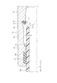
図1は本発明に係る実施形態の一部破断側面図である。この異種管接続変換継手Aは、薄肉鋼管を加工することによって形成されている。すなわち、筒状の継手本体10の軸方向中央部に径小に加工された連結壁部11を有していると共に、その継手本体10の左右に樹脂製スリーブ接続部12と金属管接続部13とが備わっている。
【0017】
樹脂製スリーブ接続部12において、継手本体10には、内周面がテーパ状の第1滑り面21として形成された第1壁部20と、この第1壁部20の一端に連設されて、内周面が、第1滑り面21の径小側端部から延出された円筒面状の第2滑り面31として形成された第2壁部30と、この第2壁部30を挟んで上記第1壁部20の反対側でその第2壁部30の一端に連設された作用部40とが設けられている。また、第1壁部20の他端に連設されて内周面が第1滑り面21の径大側端部から延出された円筒面51として形成された第3壁部50が設けられている。
【0018】
第1壁部20で囲まれた空間には抜止めリング60が配備されている。この抜止めリング60は、たとえば円周方向の一箇所が欠除された金属製の欠円リングによって形成され、それ自身の弾性に抗して拡縮径可能である。また、この抜止めリング60は、その内周縁に喰込み歯61が備わっている。そして、無負荷状態(自然状態)での抜止めリング60の内径は、後述する樹脂製スリーブ100の外周直径よりもわずかに短い長さになっている。したがって、第1壁部20で囲まれた空間に抜止めリング60が配備されているときに、継手本体10に樹脂製スリーブ100が差し込まれたときには、その樹脂製スリーブ100が抜止めリング60の内側に差し込まれると共に、抜止めリング60が樹脂製スリーブ100に弾接状態で外嵌する。そして、抜止めリング60に樹脂製スリーブ100が差し込まれるときにその外周面が抜止めリング60の喰込み歯61と擦れても、喰込み歯61が樹脂製スリーブ100の外周面を傷付けるという事態は起こりにくく、たとえ傷付けたとしても、その傷は微細な傷に過ぎなくなる。
【0019】
第3壁部50で囲まれた空間には抜止めリング保持部材70が配備されている。この抜止めリング保持部材70は、一端部の周方向複数箇所に突出部71を有し、かつ、内周側に環状突出片72を備えたゴム輪によって形成されている。また、この抜止めリング保持部材70は、上記第3壁部50に弾接して定位置に保持されていると共に、その突出部71が、第1壁部20で囲まれた空間に配備されている抜止めリング60を第1滑り面21に弾圧してその抜止めリング60を第1滑り面21と同心状に位置決めしている。この抜止めリング保持部材70は、第3壁部50の円筒面51と継手本体10に差し込まれた樹脂製スリーブ100の外周面とに密着してそれらの密着箇所を封止するシール機能を有している。
【0020】
図1のように、端部外周が面取りされた樹脂製スリーブ100が連結壁部11に当たるまで差し込まれると、その差込み途中で抜止めリング60や抜止めリング保持部材70が樹脂製スリーブ100に外嵌される。この場合、抜止めリング60は樹脂製スリーブ100に弾接状態で外嵌し、抜止めリング保持部材70は、樹脂製スリーブ100の外周面に密着し、同時に、第3壁部50の円筒面51にも密着する。そのため、継手本体10に樹脂製スリーブ100を適正長さだけ差し込んだ段階で、抜止めリング保持部材70と第3壁部50の円筒面51及び樹脂製スリーブ100の外周面との各密着箇所が封止されてシール性が発揮されるようになる。
【0021】
図2は異種管接続変換継手が抜止め機能を発揮している状態の要部拡大断面図である。
【0022】
第1滑り面21は、抜止めリング60の喰込み歯61を樹脂製スリーブ100に喰い付かせる機能と、抜止めリング60を第2滑り面31側に案内する機能とを有している。すなわち、図1の状態から樹脂製スリーブ100を引張って図2に矢印Pで示す抜出し方向に移動させたときには、樹脂製スリーブ100に弾接している抜止めリング60が樹脂製スリーブ100に伴って引抜き方向Pに移動するので、それまでは第1滑り面21に当接していた抜止めリング60を摺動させて縮径させる。こうして抜止めリング60が縮径すると、その喰込み歯61が樹脂製スリーブ100の外周面に喰い付き、この後、さらに樹脂製スリーブ100が抜出し方向に引張られて移動すると、抜止めリング60が第2滑り面31側に案内されて移行する。
【0023】
第2滑り面31は、抜止めリング60が抜出し方向Pに移動されたときに第2滑り面31に当接している抜止めリング60の外径を一定に保ったまま摺動させる機能を有する。したがって、抜止めリング60が第1滑り面21から第2滑り面31側へ移行した後では、樹脂製スリーブ100を、抜止めリング60が作用部40に当たるまでの長さ分だけ、必ず引抜き方向Pに移動させることができるようになる。このため、不測に抜止め作用が働いて樹脂製スリーブ100が不慮に抜止めされてしまうといった事態は起こらない。
【0024】
上記作用部40は、第2滑り面31を摺動して抜出し方向Pに移動されてきた抜止めリング60に当たってその抜止めリング60の抜出し方向の移動を阻止する機能を有している。このため、図2のように、管100の引抜き方向Pの移動によって抜止めリング60が作用部40に当たると、もはや樹脂製スリーブ100が引抜き方向Pには移動できなくなって抜止め作用が発揮される。
【0025】
この実施形態では、作用部40が、第2滑り面31の一端から延出された先窄まりテーパ状をなす当り面41として形成された内周面を有し、この当り面41が、抜止めリング60に当たってその抜止めリング60に縮径方向の締付力を付与する機能を有している。したがって、図2のように、抜止めリング60が作用部40の当り面41に当たった状態で樹脂製スリーブ100が引抜き方向Pに引張られたときには、管100に対する抜止めリング60の締付力ないし喰込み歯61の喰付き力がそのときの引張力に見合って増大して優れた抜止め性能が発揮される。
【0026】
以上では継手本体10の樹脂製スリーブ接続部12の構造や作用を説明したけれども、継手本体10の金属管接続部13の構造や作用についても同様である。すなわち、金属管接続部13には、テーパ状の第1滑り面21aと、この第1滑り面21aの径小側端部から延出された円筒面状の第2滑り面31aと、この第2滑り面31aを挟んで上記第1滑り面21aの反対側でその第2滑り面31aの一端に連設された作用部40aとが設けられている。また、金属管接続部13に差し込まれた金属管(不図示)に弾接状態で外嵌される弾性材でなる拡縮径可能な抜止めリング60aが上記第1滑り面21aで囲まれた空間に配備されている。そして、第1滑り面21aは、金属管に外嵌された抜止めリング60aが金属管の抜出し方向に金属管と共に移動されたときにその抜止めリング60aを摺動させて縮径させることによりその抜止めリングの内周縁を上記金属管に喰い付かせる機能と、金属管に喰い付いた抜止めリング60aを第2滑り面31a側に案内する機能とを有している。また、第2滑り面31aは、この第2滑り面31aに当接している抜止めリング60aが抜出し方向に移動されたときにその外径を一定に保ったまま抜出し方向に摺動させる機能を有している。さらに、作用部40aは、第2滑り面31aを摺動して抜出し方向に移動されてきた抜止めリング60aに当たってその抜止めリング60aの抜出し方向の移動を阻止する機能を有している。さらに、第1滑り面21aの径大側端部から延出された円筒面51aを有し、この円筒面51aで囲まれた空間に抜止めリング保持部材70aが配備されて抜止めリング60aを第1滑り面21aと同心状に位置決めしている。
【0027】
この実施形態では、継手本体10の外周面を樹脂層80によって被覆し、その樹脂層(被覆層)80の一方側及び他方側の各端部を軸方向に延出させてそれぞれの延出層81の端部内側に、シール用パッキン82を保持させてある。このものにおいて、樹脂製スリーブ接続部12側のパッキン82は、継手本体10に差し込まれた樹脂製スリーブ100に密着してその箇所にシール性を付与する機能を有している。また、金属管接続部13側のパッキン82は、継手本体10に差し込まれた金属管に密着してその箇所にシール性を付与する機能を有している。したがって、このように構成した場合には、抜止めリング保持部材70によってシール性を発揮させる必要性が必ずしもない。そのため、抜止めリング保持部材70には、抜止めリング60を第1滑り面21と同心状に位置決めする機能が備わっていれば十分であり、必ずしもシール性を発揮する機能が備わっている必要はない。
【0028】
図3は継手本体10が厚肉鋼管を切削することによって製作されている異種管接続変換継手Aの一部破断側面図、図4は図3の異種管接続変換継手Aが抜止め機能を発揮している状態の要部拡大断面図である。
【0029】
図3及び図4に示した実施形態の異種管接続変換継手Aは、継手本体10が厚肉鋼管を切削することによって製作されている点、継手本体10の外面や内面などに防錆などのために溶融亜鉛めっきや塗装が施されている点、抜止めリング保持部材70が抜止めリング60を第1滑り面21と同心状に位置決めする機能を備えているけれども、シール性を発揮する機能を備えていない点、樹脂層80を有していない点、詳細は後述する継手本体延出部10Aの端部内側にシール用パッキン82を保持させている点、において、図1及び図2で説明したものと異なっているだけであり、その他の構成や作用は図1及び図2で説明したものと同様であるので、同一又は相応する部分に同一符号を付して詳細な説明を省略する。
図3、図4において、「符号10A」は、継手本体10の軸方向一方側及び他方側の各端部から延出されたそれぞれの継手本体延出部を指し示している。この実施形態では、継手本体10の軸方向一方側及び他方側の各端部それぞれから延出された継手本体延出部10Aの端部内部に、シール用パッキン82を保持させている。詳しくは、樹脂製スリーブ接続部12側の継手本体延出部10Aには樹脂製スリーブ100に密着したパッキン82が保持され、当該パッキン82は継手本体10に差し込まれた樹脂製スリーブ100に密着してその箇所にシール性を付与する機能を有している。また、金属管接続部13側の継手本体延出部10Aには、その金属管接続部13に差し込まれる金属管(不図示)に密着するパッキン82が保持され、当該パッキン82は継手本体10に差し込まれた金属管(不図示)に密着してその箇所にシール性を付与する機能を有している。
【0030】
【0031】
【0032】
【0033】
【0034】
【発明の効果】
以上のように、本発明によると、樹脂製スリーブに樹脂管を接続し、金属管接続部に金属管を接続することによって樹脂管と金属管とを接続することができるようになる。また、継手本体に差し込んだ樹脂製スリーブの抜出し方向への移動長さを設計上適宜変更して適切な長さに定めることが可能であり、しかも、良好な抜止め機能が発揮される異種管接続変換継手を提供することが可能になる。
【0035】
本発明に係る異種管接続変換継手は、電線や通信ケーブルの保護管の管工作業に好適に用い得る。
【図面の簡単な説明】
【図1】本発明に係る実施形態の一部破断側面図である。
【図2】図1の異種管接続変換継手が抜止め機能を発揮している状態の要部拡大断面図である。
【図3】本発明に係る他の実施形態の一部破断側面図である。
【図4】図3の異種管接続変換継手が抜止め機能を発揮している状態の要部拡大断面図である。
【符号の説明】
10 継手本体
10A 継手本体延出部
12 樹脂製スリーブ接続部
13 金属管接続部
21,21a 第1滑り面
31,31a 第2滑り面
40,40a 作用部
41 当り面
60,60a 抜止めリング
70,70a 抜止めリング保持部材
80 樹脂層
81 延出層
82 パッキン
100 樹脂製スリーブ[0001]
BACKGROUND OF THE INVENTION
The present invention relates to a dissimilar pipe connection conversion joint used for connecting a metal pipe and a resin pipe.
[0002]
[Prior art]
Conventionally, there are known underground buried type joints used for pipework work that exhibit expansion and contraction action, and these joints are equipped with joints between pipes and joints during an earthquake. It helps to prevent the pipe from breaking or coming out of the joint.
[0003]
[Problems to be solved by the invention]
An object of the present invention is to provide a dissimilar pipe connection conversion joint suitable for connecting a metal pipe and a resin pipe in a joint that exhibits an expansion and contraction action and a retaining action.
[0004]
[Means for Solving the Problems]
In the dissimilar pipe connection conversion joint of the present invention, a cylindrical joint body is provided with a resin sleeve connection part and a metal pipe connection part, and the resin sleeve is inserted into the resin sleeve connection part. For this reason, the resin pipe and the metal pipe are connected via the conversion joint by connecting the resin pipe to the resin sleeve and connecting the metal pipe to the metal pipe connecting portion of the joint body. The “metal pipe” connected to the metal pipe connecting portion includes a metal pipe such as a steel pipe whose outer surface and inner surface are metal skin and does not have an inner surface coating or outer surface coating. Also included are so-called coated metal pipes that are coated with a resin or whose inner surface is coated with a resin, and metal pipes belonging to these are suitable for embedment in the ground because the coating exhibits a rust-proofing effect. Further, the “joint body” may also be one whose outer surface is not resin-coated or resin-coated.
[0005]
In the present invention, on the inner peripheral surface of the resin sleeve connecting portion , one end that is a tapered shape that gradually increases in diameter toward the insertion direction of the resin sleeve and that is the insertion side of the resin sleeve is a small diameter side end. a first sliding surface is part and the other end is the large-diameter side end portion, and the cylindrical surface shape of the second sliding surface extending from the small diameter side end portion of the first sliding surface, the first sliding surface A cylindrical surface extending from the large-diameter side end portion, and an action portion connected to one end of the second sliding surface on the opposite side of the first sliding surface across the second sliding surface. In addition, a retaining ring that can be expanded and contracted and is made of an elastic material that is externally fitted to the resin sleeve inserted into the resin sleeve connection portion is provided in the space surrounded by the first sliding surface. ing.
[0006]
The first sliding surface is formed by sliding the retaining ring to reduce the diameter when the retaining ring is moved together with the resin sleeve in the direction of extracting the resin sleeve. a peripheral causes stick bite into the resin sleeve has the ability to guide the retainer ring from the first sliding surface to the second sliding surface, said second sliding surface, the second sliding surface When the retaining ring that is in contact with is moved in the withdrawal direction, the retaining portion has a function of sliding in the withdrawal direction while maintaining the outer diameter of the retaining ring integrally. It has a function of preventing the movement of the retaining ring in the withdrawal direction when it comes into contact with the retaining ring that has been slid and moved in the withdrawal direction.
[0007]
In this dissimilar pipe connection conversion joint, since the retaining ring is disposed in the space surrounded by the tapered first sliding surface in the resin sleeve connecting portion, the inner peripheral edge of the retaining ring is the tube of the resin sleeve. The diameter is not reduced enough to bite into the wall. For this reason, there is little risk that the resin sleeve inserted into the resin sleeve connection portion will remain scratched with the retaining ring, and even if scratches remain, the scratches are small. It is easy to ensure sealing performance.
[0008]
Further, in this dissimilar pipe connection conversion joint, when the resin sleeve is moved in the removal direction, the retaining ring moves together with the resin sleeve in the removal direction. At the initial stage of movement at this time, the retaining ring slides on the first sliding surface to reduce the diameter, and the inner peripheral edge of the retaining ring bites the resin sleeve. Thereafter, when the resin sleeve is further moved in the removal direction, the retaining ring is guided from the first sliding surface to the second sliding surface side and slides with the second sliding surface along with the resin sleeve. .
[0009]
The second sliding surface has a function of sliding while keeping the outer diameter of the retaining ring in contact with the second sliding surface constant when the retaining ring is moved in the withdrawal direction. Therefore, it is possible to move the resin sleeve in the extraction direction as much as the length of the second sliding surface. Thus, plugged into the resin sleeve connection part resin sleeves are too long and fit retaining in the retainer ring immediately does not occur situation can not be moved a resin sleeve withdrawal direction.
[0010]
The retaining ring that has been slid on the second sliding surface and moved in the withdrawal direction hits the action portion and is prevented from moving in the withdrawal direction. As a result, the resin sleeve is prevented from being pulled out.
[0011]
In the present invention, the outer peripheral surface of the joint body is covered with a resin layer, and each end on one side and the other side of the coating layer extends in the axial direction, and extends from each end. Of each of the extended layers, a packing closely attached to the resin sleeve is held on the extension layer on the resin sleeve connection portion side, and the metal on the extension layer on the metal tube connection portion side The structure that the packing closely_contact | adhered to the metal pipe inserted in a pipe connection part is hold | maintained can be acted. According to this, when the heterogeneous pipe connection conversion joint is buried in the ground, the entry of soil and water into the inside of the joint body is prevented by the packing.
[0012]
In the present invention, the action portion of the resin sleeve connection portion has a tapered contact surface extending from one end of the second sliding surface on the resin sleeve connection portion side. And having a function of applying a tightening force in the reduced diameter direction to the retaining ring that has been moved in the withdrawal direction by sliding on the second sliding surface of the resin sleeve connecting portion. desirable. In this case, when the resin sleeve is pulled in the extraction direction while the retaining ring is in contact with the contact surface of the action portion, the tightening force of the retaining ring against the resin sleeve is the tensile force at that time. It increases in proportion to the force and exhibits excellent retaining performance. The inner peripheral edge of the retaining ring is preferably formed as a sharp biting tooth.
[0013]
In the present invention, the resin sleeve connecting portion has a cylindrical surface extending from the large-diameter side end portion of the first sliding surface, and is disposed in a space (inside the cylindrical surface) surrounded by the cylindrical surface. and that have a retainer ring holding member for positioning the retainer ring deployed in a space surrounded by the first sliding surface of the resin sleeve connection part to the first sliding surface and concentric. In this structure, since the retaining ring is positioned concentrically with the first sliding surface by the action of the retaining ring holding member provided in the space surrounded by the cylindrical surface, when the resin sleeve is inserted, There is no situation where the resin sleeve hits the retaining ring and cannot be inserted.
[0014]
In the present invention, the retaining ring holding member elastically sandwiches the retaining ring provided in the space surrounded by the first sliding surface of the resin sleeve connecting portion in cooperation with the first sliding surface. by that have a function of positioning the stop ring to the first sliding surface of the resin sleeve connection part and concentrically put.
[0015]
In the present invention, the metal pipe connecting portion can be configured as follows. That is, a tapered first sliding surface, a cylindrical second sliding surface extending from a small-diameter side end of the first sliding surface, and the second sliding surface are connected to the metal pipe connecting portion. And a working portion connected to one end of the second sliding surface on the opposite side of the first sliding surface, and fitted in a metal tube inserted into the metal tube connection portion in an elastic contact state. An expansion / reduction retaining ring made of an elastic material is provided in a space surrounded by the first sliding surface, and the first sliding surface on the metal tube connecting portion side is externally fitted to the metal tube. When the retaining ring is moved together with the metal tube in the direction of extracting the metal tube, the retaining ring is slid to reduce the diameter, thereby causing the inner periphery of the retaining ring to bite into the metal tube; A function of guiding the retaining ring stuck to the pipe to the second sliding surface side on the metal pipe connection side. The second sliding surface on the metal tube connecting portion side is, with the outer diameter kept constant when the retaining ring in contact with the second sliding surface is moved in the extracting direction, the extracting direction. And the action portion contacts the retaining ring that has been moved in the withdrawal direction by sliding on the second sliding surface on the metal tube connecting portion side, and is in the withdrawal direction of the retaining ring. It is possible to adopt a configuration that has a function of preventing movement.
[0016]
DETAILED DESCRIPTION OF THE INVENTION
FIG. 1 is a partially broken side view of an embodiment according to the present invention. This dissimilar pipe connection conversion joint A is formed by processing a thin steel pipe. That is, it has the connecting
[0017]
In the resin
[0018]
A retaining
[0019]
A retaining
[0020]
As shown in FIG. 1, when the
[0021]
FIG. 2 is an enlarged cross-sectional view of a main part in a state in which the dissimilar pipe connection conversion joint is exhibiting a retaining function.
[0022]
The first sliding
[0023]
The second sliding
[0024]
The
[0025]
In this embodiment, the
[0026]
Although the structure and operation of the resin
[0027]
In this embodiment, the outer peripheral surface of the joint
[0028]
3 is a partially broken side view of the dissimilar pipe connection conversion joint A manufactured by cutting the thick steel pipe by the
[0029]
The heterogeneous pipe connection conversion joint A of the embodiment shown in FIGS. 3 and 4 is such that the
3 and FIG. 4, “
[0030]
[0031]
[0032]
[0033]
[0034]
【The invention's effect】
As described above, according to the present invention, the resin tube and the metal tube can be connected by connecting the resin tube to the resin sleeve and connecting the metal tube to the metal tube connecting portion. In addition, the length of the resin sleeve inserted in the joint body in the pull-out direction can be changed to an appropriate length by design as appropriate, and a dissimilar tube that exhibits a good retaining function. It is possible to provide a connection conversion joint.
[0035]
The heterogeneous pipe connection / conversion joint according to the present invention can be suitably used for pipe work of a protective pipe for an electric wire or a communication cable.
[Brief description of the drawings]
FIG. 1 is a partially broken side view of an embodiment according to the present invention.
2 is an enlarged cross-sectional view of a main part in a state where the dissimilar pipe connection / conversion joint in FIG. 1 exhibits a retaining function.
FIG. 3 is a partially broken side view of another embodiment according to the present invention.
4 is an enlarged cross-sectional view of a main part in a state in which the dissimilar pipe connection / conversion joint in FIG. 3 exhibits a retaining function.
[Explanation of symbols]
10 Fitting body
DESCRIPTION OF
Claims (5)
上記樹脂製スリーブ接続部の内周面に、上記樹脂製スリーブの差し込み方向に向かって漸次拡径するテーパ状であって上記樹脂製スリーブの差し込み側である一端が径小側端部であり他端が径大側端部である第1滑り面と、この第1滑り面の径小側端部から延出された円筒面状の第2滑り面と、この第1滑り面の径大側端部から延出された円筒面と、この第2滑り面を挟んで上記第1滑り面の反対側でその第2滑り面の一端に連設された作用部とが設けられていると共に、樹脂製スリーブ接続部に差し込まれた樹脂製スリーブに弾接状態で外嵌された弾性材でなる拡縮径可能な抜止めリングが上記第1滑り面で囲まれた空間に配備され、
上記第1滑り面は、上記抜止めリングが樹脂製スリーブの抜出し方向に樹脂製スリーブと共に移動されたときにその抜止めリングを摺動させて縮径させることによりその抜止めリングの内周縁を上記樹脂製スリーブに喰い付かせるとともに、その抜止めリングを上記第1滑り面から上記第2滑り面側に案内する機能を有し、
上記第2滑り面は、この第2滑り面に当接している抜止めリングが上記抜出し方向に移動されたときにその外径を一体に保ったまま上記抜出し方向に摺動させる機能を有し、
上記作用部は、上記第2滑り面を摺動して上記抜出し方向に移動されてきた抜止めリングに当たってその抜止めリングの抜出し方向の移動を阻止する機能を有し、
上記第1滑り面の径大側端部から延出された上記円筒面内には、上記第1滑り面で囲まれた空間に配備された上記抜止めリングをその第1滑り面と共働して弾性的に挟み付けることによりその抜止めリングを上記第1滑り面と同心状に位置決めする抜止めリング保持部材を有していることを特徴とする異種管接続変換継手。A tubular joint body is provided with a resin sleeve connection part and a metal pipe connection part, and is a dissimilar pipe connection conversion joint in which a resin sleeve is inserted into the resin sleeve connection part,
The inner peripheral surface of the resin sleeve connecting portion has a tapered shape that gradually increases in diameter in the insertion direction of the resin sleeve, and one end on the insertion side of the resin sleeve is a small diameter side end A first sliding surface whose end is a large-diameter side end, a cylindrical second sliding surface extending from a small-diameter side end of the first sliding surface, and a large-diameter side of the first sliding surface A cylindrical surface extending from the end portion and an action portion connected to one end of the second sliding surface on the opposite side of the first sliding surface across the second sliding surface; An expansion / contraction-resistant retaining ring made of an elastic material externally fitted in a resin contact state to a resin sleeve inserted into the resin sleeve connection portion is provided in a space surrounded by the first sliding surface,
The first sliding surface has an inner peripheral edge of the retaining ring by sliding the retaining ring to reduce the diameter when the retaining ring is moved together with the resin sleeve in the direction in which the resin sleeve is withdrawn. causes stick bite into the resin sleeve has the ability to guide the retainer ring from the first sliding surface to the second sliding surface,
The second sliding surface has a function of sliding the retaining ring in contact with the second sliding surface in the extracting direction while keeping the outer diameter integrally when the retaining ring is moved in the extracting direction. ,
The working section may have a function of blocking the movement of the withdrawal direction of the retainer ring against the retainer ring that has been moved to the second sliding surface sliding to the extracting direction,
In the cylindrical surface extended from the large-diameter end of the first sliding surface, the retaining ring disposed in the space surrounded by the first sliding surface cooperates with the first sliding surface. A dissimilar pipe connection conversion joint characterized by having a retaining ring holding member that positions the retaining ring concentrically with the first sliding surface by being elastically sandwiched .
金属管接続部側の上
記第1滑り面は、金属管に外嵌された上記抜止めリングが金属管の抜出し方向に金属管と共に移動されたときにその抜止めリングを摺動させて縮径させることによりその抜止めリングの内周縁を上記金属管に喰い付かせる機能と、金属管に喰い付いた抜止めリングを金属管接続部側の上記第2滑り面側に案内する機能とを有し、
金属管接続部側の上記第2滑り面は、この第2滑り面に当接している抜止めリングが上記抜出し方向に移動されたときにその外径を一定に保ったまま上記抜出し方向に摺動させる機能を有し、
上記作用部は、金属管接続部側の上記第2滑り面を摺動して上記抜出し方向に移動されてきた抜止めリングに当たってその抜止めリングの抜出し方向の移動を阻止する機能を有している請求項1に記載した異種管接続変換継手。A tapered first sliding surface, a cylindrical second sliding surface extending from a small-diameter side end of the first sliding surface, and the second sliding surface sandwiched between the metal pipe connecting portion and the first sliding surface. An action portion connected to one end of the second sliding surface on the opposite side of the first sliding surface is provided, and is externally fitted in a resilient contact with a metal tube inserted into the metal tube connecting portion. An expansion / contraction retaining ring made of an elastic material is provided in the space surrounded by the first sliding surface,
The first sliding surface on the metal tube connecting portion side is reduced in diameter by sliding the retaining ring when the retaining ring externally fitted to the metal tube is moved together with the metal tube in the metal tube extracting direction. The retaining ring has a function of biting the inner peripheral edge of the retaining ring to the metal tube, and a function of guiding the retaining ring stuck to the metal tube to the second sliding surface side on the metal tube connecting portion side. And
The second sliding surface on the metal tube connecting portion side slides in the extraction direction while keeping the outer diameter constant when the retaining ring that is in contact with the second sliding surface is moved in the extraction direction. Has a function to move,
The action part has a function of preventing the movement of the retaining ring in the removal direction upon sliding on the retaining ring that has been moved in the withdrawal direction by sliding on the second sliding surface on the metal tube connecting part side. The dissimilar pipe connection conversion joint according to claim 1.
Priority Applications (1)
| Application Number | Priority Date | Filing Date | Title |
|---|---|---|---|
| JP2000375702A JP4610077B2 (en) | 2000-12-11 | 2000-12-11 | Heterogeneous pipe connection conversion fitting |
Applications Claiming Priority (1)
| Application Number | Priority Date | Filing Date | Title |
|---|---|---|---|
| JP2000375702A JP4610077B2 (en) | 2000-12-11 | 2000-12-11 | Heterogeneous pipe connection conversion fitting |
Publications (2)
| Publication Number | Publication Date |
|---|---|
| JP2002181263A JP2002181263A (en) | 2002-06-26 |
| JP4610077B2 true JP4610077B2 (en) | 2011-01-12 |
Family
ID=18844674
Family Applications (1)
| Application Number | Title | Priority Date | Filing Date |
|---|---|---|---|
| JP2000375702A Expired - Fee Related JP4610077B2 (en) | 2000-12-11 | 2000-12-11 | Heterogeneous pipe connection conversion fitting |
Country Status (1)
| Country | Link |
|---|---|
| JP (1) | JP4610077B2 (en) |
Cited By (1)
| Publication number | Priority date | Publication date | Assignee | Title |
|---|---|---|---|---|
| CN107002917A (en) * | 2014-09-30 | 2017-08-01 | 柔性钢管道技术公司 | Tube connector |
Families Citing this family (3)
| Publication number | Priority date | Publication date | Assignee | Title |
|---|---|---|---|---|
| CN102620071A (en) * | 2012-03-13 | 2012-08-01 | 山东华盛农业药械有限责任公司 | Blowpipe connecting structure |
| SG11201808846PA (en) | 2016-04-08 | 2018-11-29 | Flexsteel Pipeline Technologies Inc | Pipe deployment trailer |
| US10654395B1 (en) | 2016-04-08 | 2020-05-19 | Trinity Bay Equipment Holdings, LLC | Pipe deployment trailer |
Citations (3)
| Publication number | Priority date | Publication date | Assignee | Title |
|---|---|---|---|---|
| JPS54164121U (en) * | 1978-05-10 | 1979-11-17 | ||
| JPH0643473U (en) * | 1992-11-12 | 1994-06-10 | 日本鋼管継手株式会社 | Plug joint |
| JP2000120948A (en) * | 1998-10-08 | 2000-04-28 | Osaka Gas Co Ltd | Mechanical coupling connection structure |
-
2000
- 2000-12-11 JP JP2000375702A patent/JP4610077B2/en not_active Expired - Fee Related
Patent Citations (3)
| Publication number | Priority date | Publication date | Assignee | Title |
|---|---|---|---|---|
| JPS54164121U (en) * | 1978-05-10 | 1979-11-17 | ||
| JPH0643473U (en) * | 1992-11-12 | 1994-06-10 | 日本鋼管継手株式会社 | Plug joint |
| JP2000120948A (en) * | 1998-10-08 | 2000-04-28 | Osaka Gas Co Ltd | Mechanical coupling connection structure |
Cited By (2)
| Publication number | Priority date | Publication date | Assignee | Title |
|---|---|---|---|---|
| CN107002917A (en) * | 2014-09-30 | 2017-08-01 | 柔性钢管道技术公司 | Tube connector |
| CN107002917B (en) * | 2014-09-30 | 2019-08-13 | 柔性钢管道技术公司 | Tube connector |
Also Published As
| Publication number | Publication date |
|---|---|
| JP2002181263A (en) | 2002-06-26 |
Similar Documents
| Publication | Publication Date | Title |
|---|---|---|
| US6439620B1 (en) | Tube support | |
| JPH11287367A (en) | Tube fitting | |
| JP4610077B2 (en) | Heterogeneous pipe connection conversion fitting | |
| JPH02271193A (en) | Pipe joint | |
| EP1219883A3 (en) | Connector assembly | |
| WO2002042672A3 (en) | End fitting for high pressure hoses and method of mounting | |
| JP4845536B2 (en) | Anti-corrosion structure of pipe end face | |
| JP4355399B2 (en) | Plug-in fitting | |
| JP2001082650A (en) | Packing and socket structure using it | |
| JP4486343B2 (en) | Pipe holding member for resin pipe fittings | |
| JP2004138207A (en) | Inner core for soft synthetic resin pipe joint | |
| JP3993911B2 (en) | Connection structure between corrosion-resistant pipe and corrosion-resistant pipe joint | |
| JPH04163025A (en) | Eversion lining method of tube | |
| JP3003752B2 (en) | Corrosion protection cap on pipe end | |
| JPH05215284A (en) | Separation preventive coupling | |
| JP2006241894A (en) | Cut-off method between piles and water sealing material | |
| JP3594342B2 (en) | Telescopic fittings | |
| JP4663478B2 (en) | Manhole joint device and ribbed tube connection structure | |
| JP2001032972A (en) | Bell-and spigot joint | |
| JP2942152B2 (en) | How to draw buried pipes into the ground | |
| JP2004239410A (en) | Earthquakeproof joint | |
| JP3916412B2 (en) | Seismic pipe joint for propulsion method with propulsion jig | |
| JPS6249848B2 (en) | ||
| JPS6033700Y2 (en) | Conduit mouth waterproofing device | |
| JP3072150U (en) | Slide / flexible pipe system for underground wiring pipeline |
Legal Events
| Date | Code | Title | Description |
|---|---|---|---|
| A621 | Written request for application examination |
Free format text: JAPANESE INTERMEDIATE CODE: A621 Effective date: 20071107 |
|
| A977 | Report on retrieval |
Free format text: JAPANESE INTERMEDIATE CODE: A971007 Effective date: 20100430 |
|
| A131 | Notification of reasons for refusal |
Free format text: JAPANESE INTERMEDIATE CODE: A131 Effective date: 20100511 |
|
| A521 | Written amendment |
Free format text: JAPANESE INTERMEDIATE CODE: A523 Effective date: 20100709 |
|
| TRDD | Decision of grant or rejection written | ||
| A01 | Written decision to grant a patent or to grant a registration (utility model) |
Free format text: JAPANESE INTERMEDIATE CODE: A01 Effective date: 20100914 |
|
| A01 | Written decision to grant a patent or to grant a registration (utility model) |
Free format text: JAPANESE INTERMEDIATE CODE: A01 |
|
| A61 | First payment of annual fees (during grant procedure) |
Free format text: JAPANESE INTERMEDIATE CODE: A61 Effective date: 20101012 |
|
| FPAY | Renewal fee payment (event date is renewal date of database) |
Free format text: PAYMENT UNTIL: 20131022 Year of fee payment: 3 |
|
| R150 | Certificate of patent or registration of utility model |
Ref document number: 4610077 Country of ref document: JP Free format text: JAPANESE INTERMEDIATE CODE: R150 Free format text: JAPANESE INTERMEDIATE CODE: R150 |
|
| LAPS | Cancellation because of no payment of annual fees |