JP4604801B2 - Planar light source device and display device using the same - Google Patents
Planar light source device and display device using the same Download PDFInfo
- Publication number
- JP4604801B2 JP4604801B2 JP2005106123A JP2005106123A JP4604801B2 JP 4604801 B2 JP4604801 B2 JP 4604801B2 JP 2005106123 A JP2005106123 A JP 2005106123A JP 2005106123 A JP2005106123 A JP 2005106123A JP 4604801 B2 JP4604801 B2 JP 4604801B2
- Authority
- JP
- Japan
- Prior art keywords
- light source
- housing
- light
- reflection
- source device
- Prior art date
- Legal status (The legal status is an assumption and is not a legal conclusion. Google has not performed a legal analysis and makes no representation as to the accuracy of the status listed.)
- Expired - Fee Related
Links
Images


Classifications
-
- G—PHYSICS
- G02—OPTICS
- G02B—OPTICAL ELEMENTS, SYSTEMS OR APPARATUS
- G02B6/00—Light guides; Structural details of arrangements comprising light guides and other optical elements, e.g. couplings
- G02B6/0001—Light guides; Structural details of arrangements comprising light guides and other optical elements, e.g. couplings specially adapted for lighting devices or systems
- G02B6/0011—Light guides; Structural details of arrangements comprising light guides and other optical elements, e.g. couplings specially adapted for lighting devices or systems the light guides being planar or of plate-like form
- G02B6/0033—Means for improving the coupling-out of light from the light guide
- G02B6/0035—Means for improving the coupling-out of light from the light guide provided on the surface of the light guide or in the bulk of it
- G02B6/004—Scattering dots or dot-like elements, e.g. microbeads, scattering particles, nanoparticles
- G02B6/0043—Scattering dots or dot-like elements, e.g. microbeads, scattering particles, nanoparticles provided on the surface of the light guide
-
- G—PHYSICS
- G02—OPTICS
- G02F—OPTICAL DEVICES OR ARRANGEMENTS FOR THE CONTROL OF LIGHT BY MODIFICATION OF THE OPTICAL PROPERTIES OF THE MEDIA OF THE ELEMENTS INVOLVED THEREIN; NON-LINEAR OPTICS; FREQUENCY-CHANGING OF LIGHT; OPTICAL LOGIC ELEMENTS; OPTICAL ANALOGUE/DIGITAL CONVERTERS
- G02F1/00—Devices or arrangements for the control of the intensity, colour, phase, polarisation or direction of light arriving from an independent light source, e.g. switching, gating or modulating; Non-linear optics
- G02F1/01—Devices or arrangements for the control of the intensity, colour, phase, polarisation or direction of light arriving from an independent light source, e.g. switching, gating or modulating; Non-linear optics for the control of the intensity, phase, polarisation or colour
- G02F1/13—Devices or arrangements for the control of the intensity, colour, phase, polarisation or direction of light arriving from an independent light source, e.g. switching, gating or modulating; Non-linear optics for the control of the intensity, phase, polarisation or colour based on liquid crystals, e.g. single liquid crystal display cells
- G02F1/133—Constructional arrangements; Operation of liquid crystal cells; Circuit arrangements
- G02F1/1333—Constructional arrangements; Manufacturing methods
- G02F1/1335—Structural association of cells with optical devices, e.g. polarisers or reflectors
-
- G—PHYSICS
- G02—OPTICS
- G02B—OPTICAL ELEMENTS, SYSTEMS OR APPARATUS
- G02B6/00—Light guides; Structural details of arrangements comprising light guides and other optical elements, e.g. couplings
- G02B6/0001—Light guides; Structural details of arrangements comprising light guides and other optical elements, e.g. couplings specially adapted for lighting devices or systems
- G02B6/0011—Light guides; Structural details of arrangements comprising light guides and other optical elements, e.g. couplings specially adapted for lighting devices or systems the light guides being planar or of plate-like form
- G02B6/0033—Means for improving the coupling-out of light from the light guide
- G02B6/0058—Means for improving the coupling-out of light from the light guide varying in density, size, shape or depth along the light guide
- G02B6/0061—Means for improving the coupling-out of light from the light guide varying in density, size, shape or depth along the light guide to provide homogeneous light output intensity
-
- G—PHYSICS
- G02—OPTICS
- G02B—OPTICAL ELEMENTS, SYSTEMS OR APPARATUS
- G02B6/00—Light guides; Structural details of arrangements comprising light guides and other optical elements, e.g. couplings
- G02B6/0001—Light guides; Structural details of arrangements comprising light guides and other optical elements, e.g. couplings specially adapted for lighting devices or systems
- G02B6/0011—Light guides; Structural details of arrangements comprising light guides and other optical elements, e.g. couplings specially adapted for lighting devices or systems the light guides being planar or of plate-like form
- G02B6/0075—Arrangements of multiple light guides
- G02B6/0076—Stacked arrangements of multiple light guides of the same or different cross-sectional area
-
- G—PHYSICS
- G02—OPTICS
- G02B—OPTICAL ELEMENTS, SYSTEMS OR APPARATUS
- G02B6/00—Light guides; Structural details of arrangements comprising light guides and other optical elements, e.g. couplings
- G02B6/0001—Light guides; Structural details of arrangements comprising light guides and other optical elements, e.g. couplings specially adapted for lighting devices or systems
- G02B6/0011—Light guides; Structural details of arrangements comprising light guides and other optical elements, e.g. couplings specially adapted for lighting devices or systems the light guides being planar or of plate-like form
- G02B6/0075—Arrangements of multiple light guides
- G02B6/0078—Side-by-side arrangements, e.g. for large area displays
-
- G—PHYSICS
- G02—OPTICS
- G02F—OPTICAL DEVICES OR ARRANGEMENTS FOR THE CONTROL OF LIGHT BY MODIFICATION OF THE OPTICAL PROPERTIES OF THE MEDIA OF THE ELEMENTS INVOLVED THEREIN; NON-LINEAR OPTICS; FREQUENCY-CHANGING OF LIGHT; OPTICAL LOGIC ELEMENTS; OPTICAL ANALOGUE/DIGITAL CONVERTERS
- G02F1/00—Devices or arrangements for the control of the intensity, colour, phase, polarisation or direction of light arriving from an independent light source, e.g. switching, gating or modulating; Non-linear optics
- G02F1/01—Devices or arrangements for the control of the intensity, colour, phase, polarisation or direction of light arriving from an independent light source, e.g. switching, gating or modulating; Non-linear optics for the control of the intensity, phase, polarisation or colour
- G02F1/13—Devices or arrangements for the control of the intensity, colour, phase, polarisation or direction of light arriving from an independent light source, e.g. switching, gating or modulating; Non-linear optics for the control of the intensity, phase, polarisation or colour based on liquid crystals, e.g. single liquid crystal display cells
- G02F1/133—Constructional arrangements; Operation of liquid crystal cells; Circuit arrangements
- G02F1/1333—Constructional arrangements; Manufacturing methods
- G02F1/1335—Structural association of cells with optical devices, e.g. polarisers or reflectors
- G02F1/1336—Illuminating devices
- G02F1/133602—Direct backlight
- G02F1/133609—Direct backlight including means for improving the color mixing, e.g. white
Description
この発明は、反射シートを着色した面状光源装置および該装置を用いた表示装置に関する。 The present invention relates to a planar light source device in which a reflective sheet is colored and a display device using the device.
従来の面状光源装置においては、導光板の入光端面近傍の反射シートの上面に、着色ドット印刷部を設けたことにより、着色ドット印刷部により光漏れを起こす余分な光が吸収され、表示品質を損ねる蛍光管の近傍の画面上の光漏れを防止することができる(例えば、特許文献1参照)。 In the conventional planar light source device, a colored dot printing unit is provided on the upper surface of the reflection sheet in the vicinity of the light incident end surface of the light guide plate, so that extra light causing light leakage by the colored dot printing unit is absorbed and displayed. It is possible to prevent light leakage on the screen in the vicinity of the fluorescent tube that impairs the quality (for example, see Patent Document 1).
また、配光手段、発光ダイオード、配光手段と対向するように設けられた反射手段、配光手段と反射手段との間に形成された中空領域および反射体とで構成されている。(たとえば、特許文献2参照) Further, the light distribution means, the light emitting diode, the reflection means provided so as to face the light distribution means, a hollow region formed between the light distribution means and the reflection means, and a reflector are included. (For example, see Patent Document 2)
特許文献1に示された、従来の面状光源装置では、光源から発する可視光線の短波長側の光が、導光板、反射シートおよび着色ドット印刷部等で、吸収または散乱されやすいために、液晶表示装置の表示面が光源から遠ざかるにつれて赤色に変化する色ムラが生じるという問題点があった。
In the conventional planar light source device shown in
また、特許文献2に示された、従来の面状光源装置では、配光手段の一端側近郊に設けられた発光ダイオードからの光が、反射手段により一律に配光手段に向けて反射するために、発光ダイオード近傍において輝度が高く、遠ざかるにつれて輝度が低下する不均一なものとなる。このように、面状光源装置の照明光が不均一になると、表示画像に輝度ムラや色度ムラが生じ、画質が低下するという問題点があった。
Moreover, in the conventional planar light source device shown in
この発明は、上述のような課題を解決するためになされたもので、反射シートを用いた面状光源装置において、色ムラや輝度ムラが発生しない面状光源装置を得るものであり、この面状光源装置を用いることによりすぐれた表示特性を得ることができる液晶表示装置を提供することを目的とする。 The present invention has been made to solve the above-described problems, and in a planar light source device using a reflective sheet, obtains a planar light source device that does not cause color unevenness or luminance unevenness. An object of the present invention is to provide a liquid crystal display device that can obtain excellent display characteristics by using a state light source device.
この発明に係る面状光源装置は、光源から発する可視光線の波長域において、長波長側の反射率に比べ、短波長側の反射率が高い反射領域を得るために、反射シートの反光源側であって、前記筐体の底面と対向する面に着色したことを特徴とする。 The planar light source device according to the present invention provides a reflection region having a higher reflectance on the short wavelength side than on the long wavelength side in the wavelength range of visible light emitted from the light source. And the surface opposite to the bottom surface of the housing is colored .
この発明の面状光源装置は、上記の構成により、表示装置の表示面が、光源から遠ざかるにつれて赤色に変化する色ムラを相殺させることができるため、表示装置の表示面における反光源側の色ムラを抑制させることができる。
Surface light source device of this invention, the above structure, the display surface of Viewing apparatus, since color unevenness that changes to red with increasing distance from the light sources can be offset, the counter-light source side of the display surface of a display device Color unevenness can be suppressed.
実施の形態1.
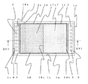
図1はこの発明を実施するための実施の形態1における面状光源装置の概略構成を示す平面図、図2は図1に示す面状光源装置の矢視II−II線の部分断面図、図3は発光ダイオード(LED)などを用いた点状光源の配列の一例を示すLED配列図、図4(a)は赤色発光ダイオードの配光分布を示した配光分布図、図4(b)は緑色および青色発光ダイオードの配光分布を示した配光分布図、図5(a)は光源を筐体の1つの側面近傍にのみ配置した場合の着色パターンの一例を示す反射シートの平面図、図5(b)は光源を筐体の対向する2つの側面近傍に配置した場合の着色パターンの一例を示す反射シートの平面図、図5(c)は他の着色パターンの一例を示す反射シートの平面図である。図1〜5において、面状光源装置の筐体1は上面1aと底面1bと4つの側面1cから構成され、上面1aには開口部1dを有している。
1 is a plan view showing a schematic configuration of a surface light source device according to
光源として、冷陰極管などの線状光源、発光ダイオード(Light Emitting Diode:以下、LEDと称す)やレーザーダイオード(Laser Diode:LD)などの点状光源が挙げられる。LEDには、青色の単色光を発する半導体発光素子と、半導体発光素子から発せられた青色光の一部を吸収し黄色の光を発する蛍光体からなる、白色のLEDがある。この実施の形態1においては、点状光源2であるLEDを使用し、赤色(R)の光を発する第1の点状光源2aと、緑色(G)の光を発する第2の点状光源2bと、青色(B)の光を発する第3の点状光源2cとから構成される。
Examples of the light source include a linear light source such as a cold cathode tube and a point light source such as a light emitting diode (hereinafter referred to as LED) and a laser diode (Laser Diode: LD). The LED includes a semiconductor light emitting element that emits blue monochromatic light and a white LED that includes a phosphor that absorbs part of the blue light emitted from the semiconductor light emitting element and emits yellow light. In the first embodiment, an LED that is a
なお、赤色のLEDにはAlInGaP半導体発光素子、青色および緑色のLEDにはInGaN半導体発光素子を用いており、赤色LEDと青色LEDまたは緑色LEDとでは半導体発光素子が異なるため、例えば図4(a)および図4(b)に示したように配光分布に違いが生じる。 Note that AlInGaP semiconductor light-emitting elements are used for red LEDs, and InGaN semiconductor light-emitting elements are used for blue and green LEDs. Since the semiconductor light-emitting elements are different between red LEDs and blue LEDs or green LEDs, for example, FIG. ) And the light distribution as shown in FIG. 4B.
赤色、緑色または青色の単色光を発するLEDは、白色光を発するLEDに比べて、発光効率が高く、液晶表示装置に用いられるカラーフィルタの赤色、緑色および青色の透過特性とLEDの発光スペクトルをあわせ込むことで、色再現性の高い表示装置を得ることができるので好ましい。また、各色ごとにLEDを独立に制御することにより、面状光源装置からの出射光の色合いおよび輝度を容易に変化することができるので好ましい。 LEDs emitting monochromatic light of red, green or blue have higher luminous efficiency than LEDs emitting white light, and the red, green and blue transmission characteristics of color filters used in liquid crystal display devices and the emission spectrum of LEDs In combination, a display device with high color reproducibility can be obtained, which is preferable. Further, it is preferable to independently control the LED for each color because the color and luminance of the emitted light from the planar light source device can be easily changed.
矩形状の点状光源基板3には、複数の点状光源2が点状光源基板3の長手方向に沿って等間隔に配列され実装されていることで、点状光源2は点状光源基板3で位置決めされている。点状光源基板3は筐体1の少なくとも1つの側面1cに沿って配設され、複数の点状光源2は筐体1の側面1cに沿って列設されることとなる。また、点状光源2は点状光源基板3に電気的にも接続され、点状光源基板3を介して外部からの電気信号を点状光源2に供給している。
A plurality of
点状光源基板3に設けられた、第1の点状光源2a、第2の点状光源2bおよび第3の点状光源2cのそれぞれの個数は必ずしも均等である必要はなく、液晶表示素子を透過したうえで所望の色度に最適化できるように第1の点状光源2a、第2の点状光源2bおよび第3の点状光源2cのそれぞれの個数を任意に設定すればよい。例えば、図3に示すように、G、B、G、R、G、Bの繰り返しの順列で配置することができる。
The numbers of the first point light source 2a, the second point light source 2b, and the third point light source 2c provided on the point
筐体1は、光が外部にできる限り漏れないようにするとともに、内側で反射して開口部1dに光が進むように、筐体1の内側となる上面1a、底面1bおよび点状光源基板3が近傍に配設されていない側面1cに、反射シート4が配置されている。反射シート4は、PP(ポリプロピレン)またはPET(ポリエチレンテレフタレート)に硫酸バリウムもしくは酸化チタンを混ぜ合わせた材料、樹脂に微細な気泡を形成した材料、金属板に銀を蒸着した材料、または金属板に酸化チタン等を含む塗料を塗布した材料からなる。
The
反射シート4は、点状光源2から発する可視光線(理科年表 平成15年(卓上版)第427頁による)の各色(紫、青、緑、黄、橙、赤)に対応する各波長域(380〜430nm、430〜490nm、490〜550nm、550〜590nm、590〜640nm、640〜770nm)において、長波長側の波長域の波長による反射率に比べ、短波長側の波長域の波長による反射率が高い第1の反射領域5aを反光源側に有する。また、長波長側の波長域の波長による反射率に比べ、短波長側の波長域の波長による反射率が低い第2の反射領域5bを光源側に有する。
The
ここで、反射シート4における筐体1の底面1bに対応する平面内において、光源に近接する辺を光源側とし、この光源側に対して遠方を反光源側とする。
Here, in the plane corresponding to the
特に、光源が筐体1の1つの側面1c近傍にのみ配置した場合には、図5(a)に示すように、光源に近接する第1の辺4aが光源側となり、この第1の辺4aに対向する第2の辺4bが反光源側となる。
In particular, when the light source is arranged only in the vicinity of one side surface 1c of the
また、光源が筐体1の対向する2つの側面1c近傍に配置した場合には、図5(b)に示すように、光源に近接する第1の辺4aおよび第2の辺4bが光源側となり、第1の辺4aおよび第2の辺4bから等間隔で遠方に位置する中央部4cが反光源側となる。
When the light source is disposed in the vicinity of the two opposing side surfaces 1c of the
この実施の形態1においては、第1の反射領域5aは、例えば、赤色および緑色に対応する波長域による反射率が50%並びに青色に対応する波長域による反射率が80%となるように、反射シート4を青色に着色したパターンである。
In the first embodiment, the first reflection region 5a has, for example, a reflectance in the wavelength region corresponding to red and green of 50% and a reflectance in the wavelength region corresponding to blue of 80%. This is a pattern in which the
また、第2の反射領域5bは、例えば、青色に対応する波長域による反射率が50%、緑色に対応する波長域による反射率が80%、および赤色に対応する波長域による反射率が90%となるように、反射シート4を橙色または赤色に着色したパターンである。
The second reflective region 5b has, for example, a reflectance of 50% in a wavelength region corresponding to blue, a reflectance of 80% in a wavelength region corresponding to green, and a reflectance in a wavelength region corresponding to red of 90%. %, The
ランプリフレクタ6は、後述する導光板7側を除いて点状光源2を包囲し、光源からの光を導光板7側に反射する。また、ランプリフレクタ6は、銀もしくはアルミニウムなどで形成される反射層を有する金属板、または白色の樹脂製シートなどの材料からなる。
The
なお、反射シート4およびランプリフレクタ6の反射率は、反射面での反射ロスを抑えるために90%以上であることが好ましい。また、筐体1の内側を白色とすることなど反射率を高めることでより一層内部での反射がよくなり、光の損失が少なくなるため好ましい。また、反射シート4とランプリフレクタ6とを別部材で構成しているが、反射シート4とランプリフレクタ6とを同一部材で一体に形成することで部材点数を減らし、組み立て作業性を向上させることができる。
In addition, it is preferable that the reflectance of the
さらに、筐体1が反射シート4およびランプリフレクタ6の機能を兼ねるようにしても部材点数を削減できるために好ましい。この場合には、反射シート4の着色パターンを筐体1の底面1bに着色することで後述する反射シート4の着色パターンによる効果を得ることができる。
Furthermore, it is preferable because the number of members can be reduced even if the
点状光源2からの光を開口部1dに伝播する導光板7を、筐体1内部に反射シート4に対して開口部1d側に配設する。導光板7は屈折率が1.4〜1.6程度のポリエチレンテレフタレート(PET)、アクリル(PMMA)もしくはポリカーボネート(PC)などの樹脂板またはガラス基板などの光を透過する機能を有するものである。
A
導光板7上には光を効果的に利用するための複数枚の光学シートからなる図示しない光学シート類を配置し、図示しない液晶表示素子を導光板7上に光学シート類を介して配置する。
An optical sheet (not shown) composed of a plurality of optical sheets for effectively utilizing light is arranged on the
なお、光学シート類はレンズシートを拡散シートで挟み込む構成である。また、輝度の向上が必要な場合には、複数枚のレンズシートをその表面に形成されるシートのプリズムの方向を考慮して組み合わせてもよい。また、拡散シートは、拡散性を向上させる場合に、2枚以上用いることが可能である。さらに、レンズシートの配光特性によってはレンズシートを1枚としてもよいし、または使用しなくてもよい。さらに、保護シート、レンズシートまたは偏光反射シートを組み合わせてもよい。また、いずれも使用しないこともでき、求める輝度や配光特性等を鑑みて最適化することが好ましい。 The optical sheets have a structure in which a lens sheet is sandwiched between diffusion sheets. In addition, when the luminance needs to be improved, a plurality of lens sheets may be combined in consideration of the direction of the prism of the sheet formed on the surface. In addition, two or more diffusion sheets can be used when improving the diffusibility. Furthermore, depending on the light distribution characteristics of the lens sheet, the lens sheet may be one or may not be used. Furthermore, you may combine a protection sheet, a lens sheet, or a polarization reflection sheet. Also, none of them can be used, and it is preferable to optimize in view of required luminance, light distribution characteristics, and the like.
面状光源装置の上部に配置される表示部として、液晶の複屈折性を応用した液晶表示素子、文字や絵が透明板に印刷された印刷物などが挙げられるが、この実施の形態1においては、表示部として液晶表示素子を用いる。 Examples of the display unit arranged on the upper part of the planar light source device include a liquid crystal display element that applies the birefringence of liquid crystal, and a printed matter in which characters and pictures are printed on a transparent plate. A liquid crystal display element is used as the display unit.
液晶表示素子は、図示しない上側または下側基板上に着色層、遮光層、スイッチング素子となる薄膜トランジスタ(以下、TFTと称す)、画素電極等の電極および配線が形成されたTFTアレイ基板および対向基板、二枚の基板を等間隔に保持するスペーサ、二枚の基板を貼り合わせるシール材、二枚の基板とのあいだに液晶を注入した後に封止する封止材、液晶に初期配向をもたせる配向膜および光を偏光させる偏光板などにより構成されるが、本発明においては、既存の液晶表示素子を用いるのでここでの説明は省略する。 A liquid crystal display element includes a TFT array substrate and a counter substrate in which electrodes and wiring such as a colored layer, a light shielding layer, a thin film transistor (hereinafter referred to as TFT) serving as a switching element, a pixel electrode, and a wiring are formed on an upper or lower substrate (not shown). , Spacers that hold the two substrates at equal intervals, a sealing material that bonds the two substrates, a sealing material that seals after injecting liquid crystal between the two substrates, an orientation that gives the liquid crystal initial alignment Although it is comprised by the film | membrane and the polarizing plate etc. which polarize light, since the existing liquid crystal display element is used in this invention, description here is abbreviate | omitted.
液晶表示素子を駆動する図示しない回路基板を備え、液晶表示素子を面状光源装置の上部に配置することで液晶表示装置を構成する。 A circuit board (not shown) for driving the liquid crystal display element is provided, and the liquid crystal display element is arranged on the top of the planar light source device to constitute a liquid crystal display device.
つぎに、点状光源2から発せられた光が導光板7の上面7aから出射して液晶表示素子に入射するまでの光路について説明する。
Next, an optical path from when the light emitted from the point
点状光源2から発せられた光は、直接またはランプリフレクタ6によって反射され、導光板7の入射面7cに入射される。
The light emitted from the point
導光板7に入射した光は、導光板7と空気層との境界で全反射を繰り返しながら導光板7内部を伝播する。導光板7の内部を伝播する光は、筐体1の開口部1dに対応する導光板7の底面7bに施された図示しないドット印刷部で拡散反射し光の伝播方向を変化させることで、導光板7と空気層との境界に対して臨界角に満たない入射角で導光板7の上面7aに入射させることができ、反射シート4を有していない筐体1の開口部1dから光を出射させることとなる。
The light incident on the
なお、一部の光は、導光板7の上面7a以外の面から出射することになるが、筐体1の底面1b、上面1aおよび側面1cに配設された反射シート4で反射することで導光板7に再び入射し、導光板7の上面7aから出射することとなる。
A part of the light is emitted from a surface other than the upper surface 7 a of the
ここで、導光板、反射シートおよびドット印刷部等は短波長側の光を吸収または散乱しやすいために、従来の反射シートを用いた面状光源装置では、導光板7内部を光が伝播するうちに長波長側の光が多くなり、導光板7の上面7aから出射する光も光源側から反光源側にかけて長波長の光、すなわち、赤色成分が多くなり、色ムラが筐体1の開口部1dで生じる。
Here, since the light guide plate, the reflection sheet, the dot printing unit, and the like easily absorb or scatter light on the short wavelength side, light propagates through the
しかしながら、この実施の形態1においては、筐体1の開口部1dにおける光源から発する光の色調変化を打ち消すような補色で、反射シート4の反光源側である第2の辺4b近傍の第1の反射領域5aを着色しているために、筐体1の開口部1dにおける色ムラを抑制している。
However, in the first embodiment, the first color near the second side 4b on the side opposite to the light source of the
また、導光板7、反射シート4およびドット印刷部等は短波長側の光を吸収または散乱しやすいために、従来の反射シートを用いた面状光源装置では、光源側に青色の色ムラが筐体1の開口部1dで生じる場合もある。
In addition, since the
しかしながら、筐体1の開口部1dにおける光源から発する光の色調変化を打ち消すような補色で、反射シート4の光源側である第1の辺4a近傍の第2の反射領域5bを着色しているために、筐体1の開口部1dにおける色ムラを抑制している。
However, the second reflection region 5b in the vicinity of the first side 4a on the light source side of the
また、図4(a)および図4(b)に示したように、赤色LEDおよび青色LEDと緑色LEDとでは配光分布に違いがあるため、従来の反射シートを用いた面状光源装置では、配光分布の違いによる色分離や色ムラが生じ、表示品位が低下してしまう。 Also, as shown in FIGS. 4 (a) and 4 (b), there is a difference in light distribution between red LEDs, blue LEDs, and green LEDs. Therefore, in a conventional planar light source device using a reflective sheet, As a result, color separation or color unevenness occurs due to a difference in light distribution, and display quality deteriorates.
しかしながら、この実施の形態1においては、面状光源装置の色調変化を打ち消すような補色で、反射シート4の反光源側に第1の反射領域5a、光源側に第2の反射領域5bを設け、各領域を着色することで、色ムラを抑制している。
However, in the first embodiment, the first reflective area 5a is provided on the side opposite to the light source of the
なお、第1の反射領域5aおよび第2の反射領域5bは、どちらか一方の反射領域のみを反射シート4に形成した場合であっても、形成した反射領域の効果は得られるので、従来の面状光源装置に比べて色ムラを抑制することができるが、反射シート4に第1の反射領域5aおよび第2の反射領域5bを有することで、光源側から反光源側にかけて色ムラを抑制することができるので好ましい。
The first reflection region 5a and the second reflection region 5b can obtain the effect of the formed reflection region even when only one of the reflection regions is formed on the
筐体1の開口部1dから出射した光は、拡散シート、保護シートまたはレンズシートなどからなる光学シート類を通過して液晶表示素子に入射する。液晶表示素子は図示しないスイッチング素子による電圧のオンまたはオフによって液晶層が配向されることで、液晶表示素子に入射した光は映像信号にあわせて変調され、赤色、緑色または青色の各色を表示する。
The light emitted from the opening 1d of the
なお、赤色(R)、緑色(G)または青色(B)の単色光を発するLEDを光源として用いる場合には、発光スペクトルの半値幅が狭く、赤色(R)、緑色(G)または青色(B)以外の発光スペクトルが少ないために、赤色、緑色および青色以外にも発光スペクトルを持つ冷陰極管に比べて、短波長側が吸収される場合の色度変化量が大きくなる傾向にある。このため、冷陰極管を光源に用いた場合ではあまり視認されなかった色ムラが、LEDを光源に用いた場合には視認されやすくなるのだが、この実施の形態1における反射シート4を用いることで、精度よく色ムラを解消することができる。
Note that when an LED that emits red (R), green (G), or blue (B) monochromatic light is used as the light source, the half-value width of the emission spectrum is narrow, and red (R), green (G), or blue ( Since there are few emission spectra other than B), the amount of change in chromaticity tends to increase when the short wavelength side is absorbed, compared to cold cathode tubes having emission spectra other than red, green and blue. For this reason, the color unevenness that is not so much visible when the cold cathode tube is used as the light source is likely to be visually recognized when the LED is used as the light source, but the
また、この実施の形態1においては、第1の反射領域5aを反射率が一定の着色パターンとしたが、光源から遠ざかるにつれて、長波長側の反射率と短波長側の反射率との差が大きくなる、つまり、光源から遠ざかるにつれて、長波長側の反射率に比べ高い短波長側の反射率が長波長側の反射率と等しくなるように漸次的に変化させる着色パターン(以下、グラデーションパターンと称す)とすることで、第1の反射領域5aの反射率が一定の着色パターンに比べ、より厳密に色ムラを相殺することができ、かつ、第1の反射領域と他の領域との切り替えが目立たなくなるので好ましい。 In the first embodiment, the first reflection region 5a is a colored pattern having a constant reflectance. However, as the distance from the light source increases, the difference between the reflectance on the long wavelength side and the reflectance on the short wavelength side is different. A color pattern (hereinafter referred to as a gradation pattern) that gradually increases so that the reflectance on the short wavelength side becomes higher than the reflectance on the long wavelength side as the distance from the light source increases. In other words, color unevenness can be canceled more strictly than in a colored pattern in which the reflectance of the first reflective region 5a is constant, and the switching between the first reflective region and another region is possible. Is preferable because it becomes inconspicuous.
また、第2の反射領域5bを反射率が一定の着色パターンとしたが、光源から遠ざかるにつれて、長波長側の反射率と短波長側の反射率との差が小さくなる、つまり、光源から遠ざかるにつれて、長波長側の反射率に比べ低い短波長側の反射率が長波長側の反射率と等しくなるグラデーションパターンとすることで、第2の反射領域5bの反射率が一定の着色パターンに比べ、より厳密に色ムラを相殺することができ、かつ、第2の反射領域と他の領域との切り替えが目立たなくなるので好ましい。 In addition, although the second reflection region 5b has a colored pattern with a constant reflectance, the difference between the reflectance on the long wavelength side and the reflectance on the short wavelength side becomes smaller as the distance from the light source increases, that is, the distance from the light source increases. Accordingly, a gradation pattern in which the reflectance on the short wavelength side, which is lower than the reflectance on the long wavelength side, is equal to the reflectance on the long wavelength side is used, so that the reflectance of the second reflective region 5b is compared with a constant colored pattern. It is preferable because color unevenness can be canceled more strictly and switching between the second reflection area and another area becomes inconspicuous.
また、着色パターンは、スクリーン印刷方式でドットパターン8を施してもよく、黒色、灰色、有色等のインクにより反射シート4に微細なパターンの印刷を施したもので、ドットの形状、大きさ、配列、濃淡、密度、インクの色およびこれらの変化は筐体1の開口部1dの表示品位を鑑みて最適化することが好ましい。
In addition, the colored pattern may be the
例えば、図5(c)に示すように、反光源側において、点状光源2から遠ざかるにつれて、長波長側の反射率と短波長側の反射率との差が大きくなるように、反射シート4に対する青色または青緑色のドットパターンの占有率を、短波長側の光の減衰率に対して相対的に高めたドットパターン8aを施してもよい。
For example, as shown in FIG. 5C, on the side opposite to the light source, as the distance from the point
また、光源側において、点状光源2から遠ざかるにつれて、長波長側の反射率と短波長側の反射率との差が小さくなるように、反射シート4に対する橙色または赤色のドットパターンの占有率を、短波長側の光の減衰率に対して相対的に低くしたドットパターン8bを施してもよい。
Further, on the light source side, the occupancy ratio of the orange or red dot pattern with respect to the
また、反射シートに着色パターンを形成する方法は、蒸着や吹き付け塗装等の方法で同様の効果をもった着色パターンを形成できるのであれば、スクリーン印刷方式に限らない。 Moreover, the method of forming a coloring pattern in a reflective sheet is not restricted to a screen printing system, if the coloring pattern with the same effect can be formed by methods, such as vapor deposition and spray painting.
さらに、反射シート4の筐体1の上面1a側に他の領域と反射率が異なる反射領域を設けることもできるが、この実施の形態1においては、反射シート4の筐体1の底面1d側(以下、裏面4dと称す)に着色することで、筐体1の上面1a側(以下、表面4eと称す)に着色する場合に比べて、筐体1の開口部1d側からの着色パターンの視認が鈍感となるために、着色パターンの印刷ムラ等の影響を受けにくいので好ましい。
Further, a reflection region having a reflectance different from that of other regions can be provided on the
特に、反射シート4の表面4eに漸次的に変化するドットパターン8を着色する場合には、ドットパターンの変化が視認されやすいので、反射シート4の裏面4dにドットパターン8を形成する場合に比べ、ドットパターン8を小さく形成する必要がある。このため、スクリーン印刷方式を用いた場合には、版の穴が目詰まりするなどの生産性が低下する。しかし、反射シート4の裏面4dにドットパターン8を設ける場合には、ドットパターン8の変化が視認されにくく、ドットパターン8を大きく形成することができるため、生産性が向上し好ましい。
In particular, when the
また、この実施の形態1においては、反射シート4の一部に第1の反射領域5aまたは第2の反射領域5bを形成したが、反射シート4の全面に、光源から発する可視光線の青色に対応する第1の波長域(430〜490nm)の波長による第1の反射率が、可視光線の赤色に対応する第2の波長域(640〜770nm)の波長による第2の反射率と、可視光線の緑色に対応する第3の波長域(490〜550nm)の波長による第3の反射率と比較して高く、かつ、第2の反射率と第3の反射率が等しい反射領域を形成することで、反射シート4における反射光が青くなるために、色ムラの対策に有益である。
In the first embodiment, the first reflection area 5a or the second reflection area 5b is formed on a part of the
また、この実施の形態1においては、反射シート4を1枚有する面状光源装置について説明したが、反射シートが複数枚からなり、そのうち少なくとも1枚に第1の反射領域5aまたは第2の反射領域5bを形成する反射シート4を有する面状光源装置であっても前述した効果が得られる。
In the first embodiment, the planar light source device having one
特に、導光板7に対向する反射シート4の表面4eに第1の反射領域5aまたは第2の反射領域5bを着色印刷した場合に、反射シート4の着色部と導光板7との密着により、第1の反射領域5aまたは第2の反射領域5bとそれ以外の領域との熱や吸水による伸びの違いなどから反射シート4にシワ等を生じやすい。
In particular, when the first reflective region 5a or the second reflective region 5b is colored and printed on the surface 4e of the
また、反射シート4の着色部で、反射シート4と導光板7との間隙の空気層がなくなり、これまで導光板7と空気層の界面である底面7bで全反射していた光が、着色部に直接到達し、散乱および反射され、反射シート4の着色部近傍の導光板7の上面7aから出射されるため、色ムラが生じることとなる。
Further, in the colored portion of the
また、反射シートの裏面4dに反射領域を形成した場合には、反射シートの着色部と筐体1の底面1bとの密着により、着色領域とそれ以外の領域との熱や吸水による伸びの違いなどから反射シートにシワ等を生じやすい。
In addition, when a reflective region is formed on the
これに対し、面内で反射率が異なる反射領域をもつ反射シート4(以下、第1の反射シートと称す)の反射領域をもつ面が、他の反射シートに対して対向するように配置することで、反射シート同士の密着が生じたとしても反射シートの材質が同じであるために、第1の反射シートのシワ等を回避できるので好ましい。 On the other hand, the surface having the reflection region of the reflection sheet 4 (hereinafter referred to as the first reflection sheet) having reflection regions having different reflectivities in the surface is arranged to face the other reflection sheet. Thus, even if the reflection sheets are closely adhered to each other, it is preferable because the material of the reflection sheets is the same, so that wrinkles of the first reflection sheet can be avoided.
なお、反射領域は、前述した第1の反射領域5aおよび第2の反射領域5bの上位概念である、光源から発する可視光線の各色に対応する各波長域において、少なくとも1つの波長域の波長による反射率と、残りの波長域の波長による反射率とが異なる領域を含むものである。 Note that the reflection region depends on the wavelength of at least one wavelength region in each wavelength region corresponding to each color of visible light emitted from the light source, which is a superordinate concept of the first reflection region 5a and the second reflection region 5b described above. It includes a region where the reflectance and the reflectance depending on the wavelength of the remaining wavelength region are different.
また、反射領域は、さらに上位概念である、面内で反射率が異なる領域を含むものであり、例えば、第1の反射シートにおける、赤色に対応する波長域の波長による反射率R、緑色に対応する波長域の波長による反射率G、および青色に対応する波長域の波長による反射率Bをそれぞれ90%とすると、反射領域は、反射率R、G、Bをそれぞれ50%として全体の反射率を下げただけの灰色着色とする領域である。この場合には輝線対策として有効である。 Further, the reflection region includes a region having a different reflectivity within the plane, which is a more general concept. For example, in the first reflection sheet, the reflectivity R by the wavelength of the wavelength region corresponding to red, green Assuming that the reflectance G due to the wavelength in the corresponding wavelength region and the reflectance B due to the wavelength in the wavelength region corresponding to blue are each 90%, the reflection region has the reflectances R, G, and B as 50%, respectively. It is an area to be gray colored just by reducing the rate. In this case, it is effective as a bright line countermeasure.
さらに、複数の反射シートのうち、筐体1の開口部1d側の反射シートの反射率が、筐体1の底面1b側の反射シートの反射率と比較して低くすることで、筐体1の開口部1d側の反射シートを透過させ、第1の反射シートの反射領域をもつ面に到達する光を増加することができるので、より効果的に輝度ムラおよび色ムラを軽減できる。また、筐体1の底面1b側の反射シートの反射率を高くすることで光の利用効率を高めることができる。
Further, among the plurality of reflective sheets, the reflectance of the reflective sheet on the opening 1d side of the
すなわち、複数の反射シートのうち、筐体1の開口部1d側の反射シートの反射率を調整することで、筐体1の開口部1d側の反射シートを透過させ反射領域に到達する光を調整することができるので、より効果的に輝度ムラおよび色ムラを軽減できる。
That is, by adjusting the reflectance of the reflection sheet on the opening 1d side of the
また、複数の反射シートの対向する面を接着層により接着することで、シートを1つにまとめることができ、面状光源装置の組立てが容易になる。この場合に、接着層と反射シートの屈折率とを一致させることで、この反射シートと接着面との境界における屈折がなく好ましい。 Further, by bonding the opposing surfaces of the plurality of reflective sheets with the adhesive layer, the sheets can be combined into one, and the surface light source device can be easily assembled. In this case, it is preferable that the refractive index of the adhesive layer and the reflective sheet be matched so that there is no refraction at the boundary between the reflective sheet and the adhesive surface.
また、この実施の形態1においては、反射シート4に第1の反射領域5aまたは第2の反射領域5bを形成したが、反射シート4に第1の反射領域5aまたは第2の反射領域5bを形成する替わりに、面内で透過率が異なる透過領域をもつ色変換シートを反射シートに対して筐体1の開口部1d側に配置することで、反射シート4の着色による効果と同様の効果を得ることができる。
In the first embodiment, the first reflection region 5a or the second reflection region 5b is formed on the
なお、この色変換シートとは、特定の波長の光のみを透過させるシートであり、例えば、透明の薄紙状の色セロファンなどがある。 The color conversion sheet is a sheet that transmits only light of a specific wavelength, and includes, for example, transparent thin paper-like color cellophane.
また、色変換シートは、光源から発する可視光線の各色に対応する各波長域において、長波長側の波長域の波長による透過率に比べ、短波長側の波長域の波長による透過率が高い第1の透過領域を反光源側に、長波長側の波長域の波長による透過率に比べ、短波長側の波長域の波長による透過率が低い第2の透過領域を光源側に有することで、前述した反射シート4の着色による効果と同様の効果を得ることができるので好ましい。
In addition, the color conversion sheet has a high transmittance due to the wavelength in the short wavelength side compared to the transmittance due to the wavelength in the long wavelength side in each wavelength range corresponding to each color of visible light emitted from the light source. By having a second transmission region on the light source side, the transmission region of 1 is low on the side opposite to the light source, and the transmittance on the wavelength region on the short wavelength side is lower than the transmittance on the wavelength region on the short wavelength side. Since the effect similar to the effect by coloring of the
さらに、前述した光学シート類に、反射シート4に対して筐体1の開口部1d側に配置した選択性反射シートを加えることで、筐体1の開口部1dから出射して選択性反射シートに入射した光の一部を、反射シート4側に反射することによって反射シート4に到達する光を増加させ、より効果的に輝度ムラおよび色ムラを軽減することができる。
Furthermore, by adding a selective reflection sheet disposed on the opening 1d side of the
なお、この選択性反射シートは、輝度上昇効果を有するシートであり、ほぼ垂直に入射した光を2回の全反射で反射シート4側に戻すプリズム形状をもつプリズムシートや、偏光性能を有するシートであり、偏光方向によって反射光と透過光に分離する反射型偏光シートなどである。
This selective reflection sheet is a sheet having a luminance increasing effect, and a prism sheet having a prism shape that returns light that is incident substantially perpendicular to the
以上のように、この発明の実施の形態1にかかわる面状光源装置によれば、反射シート4の第1の反射領域5aを青色または青緑色に着色することで、第1の反射領域5aにおける、長波長側に比べ短波長側の光の反射量を増加させることができるので、光源側から反光源側にかけて赤色に変化する色ムラを相殺し、筐体1の開口部1dにおける色ムラを抑制することができる。
As described above, according to the planar light source device according to the first embodiment of the present invention, the first reflection region 5a of the
また、反射シート4の第2の反射領域5bを橙色または赤色に着色することで、第2の反射領域5bにおける、短波長側に比べ長波長側の光の反射量を増加させることができるので、光源側の青色の色ムラを相殺し、筐体1の開口部1dにおける色ムラを抑制することができる。
In addition, since the second reflection region 5b of the
実施の形態2.
図6はこの発明の実施の形態2にかかわる面状光源装置の概略構成を示す平面図、図7は図6に示す面状光源装置の矢視VII−VII線の部分断面図である。図6および図7において、図1〜5と同じ符号は、同一または相当部分を示し、その説明を省略する。
6 is a plan view showing a schematic configuration of a planar light source device according to
9は混色導光板であり、この混色導光板9は、対向する一対の上面9a、底面9bと、この上面9a、底面9bの端縁を結んだ複数の側面のうち、対向する一対の面である入射面9cおよび出射面9dから構成されている。混色導光板9はすべての面が鏡面であることが好ましい。
ランプリフレクタ6が、点状光源2からの光を混色導光板9の入射面9cへ集光するために、点状光源2の周囲に配置されている。矩形状の導光板7は、入射面7cが混色導光板9の出射面9dと略平行に配置され、上面7aを発光面としている。
A
混色導光板9の材料としては、主に光の透過率が高いPMMA(ポリメチルメタクリレート)、PC(ポリカーボネート)またはガラスなどが用いられる。
As a material of the color mixture
反射板10は、混色導光板9の出射面9dから出射した光を導光板7の入射面7cに導くように配置され、反射板10の反射面が導光板7の上面7aおよび入射面7cに垂直な平面に対する断面形状が半円である。
The
導光板7の底面7bには、光反射手段である反射シート4が配置されている。
ここで、反射シート4における筐体1の底面1bに対応する平面内において、光源に近接する辺を光源側とし、この光源側に対して遠方を反光源側としており、この実施の形態2においては、導光板7の入射面7c側が反射シート4の光源側となる。
On the bottom surface 7 b of the
Here, in the plane corresponding to the
特に、図6および図7に示すように、混色導光板9が2個存在し、導光板7の入射面7cが2面である場合には、図5(b)に示すように、光源に近接する第1の辺4aおよび第2の辺4bが光源側となり、第1の辺4aおよび第2の辺4bから等間隔で遠方に位置する中央部4cが反光源側となる。
In particular, as shown in FIGS. 6 and 7, when there are two color mixing
また、混色導光板9が導光板7下の入射面7c側に1個存在し、導光板7の入射面7cが1面のみである場合には、図5(a)に示すように、光源に近接する第1の辺4aが光源側となり、この第1の辺4aに対向する第2の辺4bが反光源側となる。
In addition, when there is one color mixing
つぎに点状光源2から発せられた光が混色導光板9および導光板7を通過したのち、筐体1の開口部1dから出射するまでの光路について説明する。
Next, a description will be given of an optical path from when the light emitted from the point
点状光源2である第1の点状光源2a、第2の点状光源2bおよび第3の点状光源2cから発せられた赤色、緑色および青色の単色光は、直接またはランプリフレクタ6によって反射され、入射面9cから混色導光板9に入射する。
Red, green and blue monochromatic light emitted from the first point light source 2a, the second point light source 2b and the third point light source 2c, which are the point
混色導光板9に入射する単色光は、混色導光板9と空気との屈折率の違いにより全反射を繰り返しながら混色導光板9内部を伝搬していく。単色光は混色導光板9内部を伝搬していくうちに広がるので、複数の点状光源2から発せられた赤色、緑色および青色の単色光は混色され白色光に均一化され、混色導光板9の出射面9dから出射することとなる。
The monochromatic light incident on the mixed color
混色導光板9の出射面9dから出射した光は、反射板10で反射され、導光板7の入射面7cから入射する。導光板7に入射した光は、導光板7と空気との屈折率の違いにより全反射を繰り返しながら導光板7内部を伝搬していく。上面7aと対向する底面7bには、図示しないドット印刷部が形成されており、ドット印刷部に光があたり拡散反射することで、光の全反射条件が破られ上面7aから光が出射する。また、導光板7の底面7bから出射された光は反射シート4によって反射され、再び導光板7に入射する。以上により、筐体1の開口部1dから光を出射させることとなる。
The light emitted from the exit surface 9 d of the color mixture
なお、実施の形態1における面状光源装置に、混色導光板9を追加するところのみが実施の形態1と異なるところであり、後述する混色導光板9による作用効果以外は、実施の形態1と同様の作用効果を奏する。
Note that only the addition of the color mixture
この発明の実施の形態1の液晶表示装置によれば、点状光源2から発せられた赤色、緑色および青色の単色光は、混色導光板9を介すことで、白色光として導光板に入射できるうえに、点状光源であった光源が面状光源化され、導光板4の入射面7cにおける入射光の強度が均一となり、導光板7内部の入射面7cの近傍での色度ムラおよび輝度ムラの発生を抑制することができる。
According to the liquid crystal display device of the first embodiment of the present invention, the red, green and blue monochromatic lights emitted from the point
実施の形態3.
図8はこの発明の実施の形態3にかかわる面状光源装置の概略構成を示す平面図、図9は図8に示す面状光源装置の矢視IX−IX線の部分断面図、図10(a)は光源を筐体の1つの側面近傍にのみ配置した場合の着色パターンの一例を示す反射シートの平面図、図10(b)は光源を筐体の対向する2つの側面近傍に配置した場合の着色パターンの一例を示す反射シートの平面図、図11(a)は光源を筐体の1つの側面近傍にのみ配置した場合の着色パターンの他の一例を示す反射シートの平面図、図11(b)は光源を筐体の対向する2つの側面近傍に配置した場合の着色パターンの他の一例を示す反射シートの平面図、図11(c)はさらに他の着色パターンの一例を示す反射シートの平面図である。図8〜図11において、図1〜7と同じ符号は、同一または相当部分を示し、その説明を省略する。
8 is a plan view showing a schematic configuration of a planar light source device according to
筐体1の開口部1d全体には拡散板11を配設する。拡散板11はポリエチレンテレフタレート(PET)、アクリル(PMMA)もしくはポリカーボネート(PC)などの樹脂板またはガラス基板などの光を透過する機能を有するものである。また、拡散板11に反射材を混入したものや表面を粗面化したものを用い、入射した光を拡散する機能をもたせることで、広い指向性をもつ面状光源装置を得ることができるため好ましい。
A
筐体1は、光が外部にできる限り漏れないようにするとともに、内側で反射して開口部1dに光が進むように、筐体1の内側となる底面1bおよび点状光源基板3が近傍に配設されていない側面1cに、反射シート12が配設されている。この反射板12と拡散板11との間に中空領域13を形成することで、光は中空領域13にある空気中を伝播する。
The
点状光源基板3は、筐体1の対向する2つの側面1cに沿って配設され、複数の点状光源2は筐体1の側面1cに沿って列設されることとなる。
The point
ランプリフレクタ6は、中空領域13側を除いて点状光源2を包囲し、光源からの光を中空領域13側に反射する。
The
反射シート12は、前述した反射シート4の第1の反射領域5aと第2の反射領域5bとの位置を入れ替えたものである。すなわち、長波長側の波長域の波長による反射率に比べ、短波長側の波長域の波長による反射率が高い第1の反射領域5aを光源側に有する。また、長波長側の波長域の波長による反射率に比べ、短波長側の波長域の波長による反射率が低い第2の反射領域5bを反光源側に有する。
The
ここで、反射シート12における筐体1の底面1bに対応する平面内において、光源に近接する辺を光源側とし、この光源側に対して遠方を反光源側とする。
Here, in the plane corresponding to the
特に、光源を筐体1の1つの側面1c近傍にのみ配置した場合には、図10(a)に示すように、光源に近接する第1の辺12aが光源側となり、この第1の辺12aに対向する第2の辺12bが反光源側となる。
In particular, when the light source is disposed only in the vicinity of one side surface 1c of the
また、光源が筐体1の対向する2つの側面1c近傍に配置した場合には、図10(b)に示すように、光源に近接する第1の辺12aおよび第2の辺12bが光源側となり、第1の辺12aおよび第2の辺12bから等間隔で遠方に位置する中央部12cが反光源側となる。
Further, when the light source is disposed in the vicinity of the two opposite side surfaces 1c of the
なお、この実施の形態3においては、第1の反射領域5aは、例えば、赤色に対応する波長域による反射率が85%ならびに青色および緑色に対応する波長域による反射率が90%となるように、反射シート12をシアン色に着色したパターンである。
In the third embodiment, the first reflective region 5a has, for example, a reflectance of 85% in the wavelength region corresponding to red and a reflectance of 90% in the wavelength regions corresponding to blue and green. In addition, the
また、第2の反射領域5bは、例えば、青色に対応する波長域による反射率が80%、緑色に対応する波長域による反射率が85%、および赤色に対応する波長域による反射率が90%となるように、反射シート12を橙色または赤色に着色したパターンである。
The second reflective region 5b has, for example, a reflectance of 80% in a wavelength region corresponding to blue, a reflectance of 85% in a wavelength region corresponding to green, and a reflectance in a wavelength region corresponding to red of 90%. %, The
つぎに、点状光源2から発せられた光が拡散板11から出射するまでの光路について説明する。
Next, an optical path until the light emitted from the point
点状光源2である第1の点状光源2a、第2の点状光源2bおよび第3の点状光源2cから発せられた赤色、緑色および青色の単色光は、直接またはランプリフレクタ6によって反射され、中空領域13に導かれる。
Red, green and blue monochromatic light emitted from the first point light source 2a, the second point light source 2b and the third point light source 2c, which are the point
中空領域13において、筐体1の底面1bに向けて出射した光は、反射シート12の正反射材により正反射され、光源から反光源側に向かって光を伝播する。
In the
拡散板11に入射した光は、拡散板11内を透過する光の成分と拡散板11内の粒子で反射する光の成分に分かれる。このうち、筐体1の底面1b側に反射した成分の光は、反射シート12で正反射して、再度、拡散板11に入射する。また、拡散板11に入射し透過した成分の光は、あらゆる方向に放射する。
The light that has entered the
拡散板11から出射した光は、拡散シート、保護シートまたはレンズシートなどからなる光学シート類を通過して液晶表示素子に入射する。液晶表示素子は図示しないスイッチング素子による電圧のオンまたはオフによって液晶層が配向されることで、液晶表示素子に入射した光は映像信号にあわせて変調され、赤色、緑色または青色の各色を表示する。
The light emitted from the
なお、この実施の形態3においては、導光板7を配置せず、筐体1の開口部1d全体には拡散板11を配設したうえで、反射シート12が前述した反射シート4の第1の反射領域5aと第2の反射領域5bとの位置を入れ替えたところのみが実施の形態1と異なるところであり、後述する反射シート12による作用効果以外は、実施の形態1と同様の作用効果を奏する。
In the third embodiment, the
この実施の形態3においては、導光板を使用しないことにより、面状光源装置の重量および厚みが増すことがなく、薄型軽量化を図ることができる。 In the third embodiment, by not using the light guide plate, the weight and thickness of the planar light source device are not increased, and a reduction in thickness and weight can be achieved.
また、この実施の形態3においては、導光板7および導光板7に形成するドット印刷部がないために、導光板7およびドット印刷部で短波長側の光を吸収または散乱されることがない。
Further, in the third embodiment, since there is no dot printing portion formed on the
このため、従来の反射シートを用いた面状光源装置において、導光板内部を光が伝播するうちに、光源側から反光源側にかけて赤色に変化する色ムラが生じることもなく、筐体1の開口部1dにおける光源から発する光の色調変化を打ち消すような補色で、反射シート4の反光源側である第2の辺4b近傍の第1の反射領域5aを着色する必要はない。また、光源側に青色の色ムラが筐体1の開口部1dで生じることもなく、筐体1の開口部1dにおける光源から発する光の色調変化を打ち消すような補色で、反射シート4の光源側である第1の辺4a近傍の第2の反射領域5bを着色する必要もない。
For this reason, in the planar light source device using the conventional reflective sheet, while light propagates inside the light guide plate, color unevenness that changes to red from the light source side to the non-light source side does not occur, and the
その反面、導光板7を使用しないために、より光源の配光分布を反映した輝度分布となる。すなわち、図4(a)および図4(b)に示すように、発光色によって配光分布が異なると、従来の反射シートを用いた面状光源装置においては、筐体1の開口部1dにおいて光源側に赤色の色ムラが生じ、反光源側にシアン色といった色ムラが生じる。
On the other hand, since the
しかしながら、この実施の形態3においては、筐体1の開口部1dにおける光源から発する光の色調変化を打ち消すような補色で、反射シート12の反光源側である中央部12cの第2の反射領域5bを着色しているために、筐体1の開口部1dにおける色ムラを抑制している。
However, in the third embodiment, the second reflection region of the
また、筐体1の開口部1dにおける光源から発する光の色調変化を打ち消すような補色で、反射シート12の光源側である第1の辺12aおよび第2の辺12b近傍の第1の反射領域5aを着色しているために、筐体1の開口部1dにおける色ムラを抑制している。
Further, the first reflection region in the vicinity of the first side 12a and the second side 12b on the light source side of the
なお、第1の反射領域5aおよび第2の反射領域5bは、どちらか一方の反射領域のみを反射シート12に形成した場合であっても、形成した反射領域の効果は得られるので、従来の面状光源装置に比べて色ムラを抑制することができるが、反射シート12に第1の反射領域5aおよび第2の反射領域5bを有することで、光源側から反光源側にかけて色ムラを抑制することができるので好ましい。
The first reflection region 5a and the second reflection region 5b can obtain the effect of the formed reflection region even when only one of the reflection regions is formed on the
また、反射シート12の裏面12dに着色することで、表面12eに着色する場合に比べて、筐体1の開口部1d側からの着色パターンの視認が鈍感となるために、着色パターンの印刷ムラ等の影響を受けにくいので好ましい。
Further, since the back surface 12d of the
また、この実施の形態3においては、赤色、緑色または青色の単色光を発するLEDを点状光源2として用いたが、白色光を発する白色LEDを用いた場合には、図11(b)に示すように、面状光源装置から出射する光の輝度ムラを打ち消すように、反射シート12の光源に近接する第1の辺12aおよび第2の辺12b近傍に、反射率が他の領域に比べ低い第3の反射領域5cを設けることで、面状光源装置の輝度ムラを抑制することができる。
In
これは、従来の反射シートを用いた面状光源装置では、拡散板11から出射する光の輝度分布をランプリフレクタ6および反射シート12の形状で制御しているのだが、点状光源2からランプリフレクタ6または反射シート12を介さず拡散板11に到達する光は制御することができずに、光源近傍で輝度が高くなり、輝度ムラが生じ表示品位が低下してしまうという問題点を解決することができる。
This is because, in a conventional planar light source device using a reflective sheet, the luminance distribution of light emitted from the
例えば、反射シート12に、光源に近接する第1の辺12aおよび第2の辺12b近傍に反射率が面内の他の領域と異なる第3の反射領域5cを設け、この第3の反射領域5cの反射率は85%、他の領域の反射率は90%とする。
For example, the
また、図11(c)に示すように、点状光源2から遠ざかるにつれて、灰色のドットパターンの占有率を減少させるようなドットパターン8を施してもよい。
Further, as shown in FIG. 11C, a
なお、光源を筐体1の1つの側面1c近傍にのみ配置した場合には、図11(a)に示すように、光源に近接する第1の辺12aのみが光源側となり、この近傍に反射率が他の領域に比べ低い第3の反射領域5cが設けることで、面状光源装置の輝度ムラを抑制することができる。
When the light source is disposed only near one side surface 1c of the
以上のように、この実施の形態3にかかわる面状光源装置によれば、反射シートが、光源から発する可視光線に対応する波長域において、少なくとも一部の波長に対する反射率が異なる反射領域をもつことにより、従来の面状光源装置の光源からの距離に応じて生じる輝度ムラや色ムラを相殺させ抑制することができる。 As described above, according to the planar light source device according to the third embodiment, the reflective sheet has a reflective region having different reflectivities for at least some wavelengths in the wavelength region corresponding to the visible light emitted from the light source. Thereby, luminance unevenness and color unevenness generated according to the distance from the light source of the conventional planar light source device can be offset and suppressed.
実施の形態4.
図12はこの発明の実施の形態4にかかわる面状光源装置の概略構成を示す平面図、図13は図12に示す面状光源装置の矢視XIII−XIII線の部分断面図、図14は着色パターンの一例を示す反射シートの平面図である。図12〜図14において、図1〜11と同じ符号は、同一または相当部分を示し、その説明を省略する。
12 is a plan view showing a schematic configuration of a surface light source device according to
筐体1は、光が外部にできる限り漏れないようにするとともに、内側で反射して開口部1dに光が進むように、筐体1の内側となる底面1bおよび点状光源基板3が近傍に配設されていない側面1cに、反射シート14が配設されている。この反射シート14と拡散板11との間に中空領域13を形成することで、光は中空領域13にある空気中を伝播する。
The
反射シート14は、前述した反射シート12の光源側および反光源側の定義が異なるだけであり、長波長側の波長域の波長による反射率に比べ、短波長側の波長域の波長による反射率が高い第1の反射領域5aを光源側に有すること、長波長側の波長域の波長による反射率に比べ、短波長側の波長域の波長による反射率が低い第2の反射領域5bを反光源側に有することは同一である。
The
つまり、この実施の形態4においては、図13および図14に示すように、反射シート14における筐体1の底面1bに対応する平面内において、光源の近傍が光源側となり、この光源側に対して遠方である、隣接する点状光源2間および筐体1の側面1c側が反光源側となる。
That is, in the fourth embodiment, as shown in FIGS. 13 and 14, in the plane corresponding to the
反射シート14には、点状光源2を挿入するための穴19を設けている。
A
なお、この実施の形態4において、第1の反射領域5aは、例えば、赤色に対応する波長域による反射率が75%、緑色に対応する波長域による反射率が87%、青色に対応する波長域による反射率が90%となるように、反射シート14を青色またはシアン色に着色したパターンである。
In the fourth embodiment, the first reflective region 5a has, for example, a reflectance in the wavelength region corresponding to red of 75%, a reflectance in the wavelength region corresponding to green of 87%, and a wavelength corresponding to blue. This is a pattern in which the
また、第2の反射領域5bは、例えば、青色に対応する波長域による反射率が88%、緑色に対応する波長域による反射率が88%、および赤色に対応する波長域による反射率が90%となるように、反射シート14を赤色に着色したパターンである。
The second reflective region 5b has, for example, a reflectance of 88% in a wavelength region corresponding to blue, a reflectance of 88% in a wavelength region corresponding to green, and a reflectance in a wavelength region corresponding to red of 90%. %, The
つぎに、点状光源4から発せられた光が拡散板11から出射するまでの光路について説明する。
Next, an optical path until the light emitted from the point
点状光源2である第1の点状光源2a、第2の点状光源2bおよび第3の点状光源2cから発せられた赤色、緑色および青色の単色光は、直接または反射シート14によって反射され、拡散板11に導かれる。
The red, green, and blue monochromatic light emitted from the first point light source 2a, the second point light source 2b, and the third point light source 2c, which are the point
拡散板11に入射した光は、拡散板11内を透過する光の成分と拡散板11内の粒子で反射する光の成分に分かれる。そのうち、光源側に反射した成分の光は、反射シート14で正反射、拡散反射もしくはその複合で反射して、再度、拡散板11に入射する。また、拡散板11に入射し透過した成分の光は、拡散板11表面からあらゆる方向に均一に放射する。
The light that has entered the
なお、この実施の形態4においては、点状光源2を筐体1の開口部1dの直下に配置し、導光板7を配置せず、筐体1の開口部1d全体に拡散板11を配設したうえで、反射シート14の第1の反射領域5aおよび第2の反射領域5bの位置が異なるところのみが実施の形態1と異なるところであり、後述する反射シート14による作用効果以外は、実施の形態1と同様の作用効果を奏する。
In the fourth embodiment, the point
この実施の形態4によれば、従来の直下型の面状光源装置の場合に起こり得る、拡散板11の表面における点状光源2が存在する部分が赤色で、その周辺の部分が青色となる色ムラを、その補色で反射シート14に着色することで、色ムラを相殺し、筐体1の開口部1dにおける色ムラを抑制することができる。
According to the fourth embodiment, the portion where the point
なお、第1の反射領域5aおよび第2の反射領域5bは、どちらか一方の反射領域のみを反射シート14に形成した場合であっても、形成した反射領域の効果は得られるので、従来の面状光源装置に比べて色ムラを抑制することができるが、反射シート14に第1の反射領域5aおよび第2の反射領域5bを有することで、光源側から反光源側にかけて色ムラを抑制することができるので好ましい。
The first reflection region 5a and the second reflection region 5b can obtain the effect of the formed reflection region even when only one of the reflection regions is formed on the
また、反射シート14の裏面14dに着色することで、表面14eに着色する場合に比べて、筐体1の開口部1d側からの着色パターンの視認が鈍感となるために、着色パターンの印刷ムラ等の影響を受けにくいので好ましい。
Further, coloring the back surface 14d of the
実施の形態5.
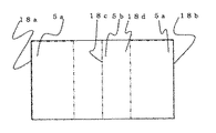
図15はこの発明の実施の形態5にかかわる面状光源装置の概略構成を示す平面図、図16は図15に示す面状光源装置の矢視XVI−XVI線の部分断面図、図17は着色パターンの一例を示す反射シートの平面図である。図15〜図17において、図1〜14と同じ符号は、同一または相当部分を示し、その説明を省略する。
15 is a plan view showing a schematic configuration of a surface light source device according to
この実施の形態5においては、導光板を上下に2枚重ねて備えており、筐体1の開口部1d側の導光板を第1の導光板15、筐体1の底面1b側の導光板を第2の導光板16とする。
In the fifth embodiment, two light guide plates are provided one above the other, and the light guide plate on the opening 1d side of the
第1の導光板15の底面15bおよび第2の導光板16の底面16bには、第1の導光板15の入射面15cおよび第2の導光板16の入射面16cに対向する面から略中央部まで、それぞれ光出射手段17が形成されている。
The bottom surface 15b of the first light guide plate 15 and the bottom surface 16b of the second
この光出射手段17は、例えば、スクリーン印刷方式によるドットパターン、または、底面15bおよび16bをエッチング、スクライビング、若しくはサンドブラスト加工することにより楔またはリッジで構成することで得られる。また、ドットパターン、楔またはリッジを施した部材を貼り付けてもよい。 The light emitting means 17 can be obtained, for example, by forming a dot pattern by a screen printing method or a wedge or a ridge by etching, scribing, or sandblasting the bottom surfaces 15b and 16b. Moreover, you may affix the member which gave the dot pattern, the wedge, or the ridge.
筐体1は、光が外部にできる限り漏れないようにするとともに、内側で反射して開口部1dに光が進むように、筐体1の内側となる上面1a、底面1bおよび点状光源基板3が近傍に配設されていない側面1cに、反射シート18が配設されている。
The
反射シート18は、前述した反射シート4の光源側および反光源側の位置が異なるだけであり、長波長側の波長域の波長による反射率に比べ、短波長側の波長域の波長による反射率が高い第1の反射領域5aを反光源側に有することは同一である。
The
つまり、この実施の形態5においては、図16および図17に示すように、反射シート18における筐体1の底面1bに対応する平面内において、第1の導光板15の入射面15cに対向する面側に位置する辺である、第1の辺18aが反光源側となる。また、反射シート18における筐体1の底面1bに対応する平面内において、第2の導光板16の入射面16cに対向する面側に位置する辺である、第2の辺18bが反光源側となる。
That is, in the fifth embodiment, as shown in FIGS. 16 and 17, the reflecting
すなわち、第1の辺18aおよび第2の辺18bが反光源側となり、第1の辺18aおよび第2の辺18bから等間隔で遠方に位置する中央部18cが光源側となる。 In other words, the first side 18a and the second side 18b are on the side opposite to the light source, and the central portion 18c located far from the first side 18a and the second side 18b is on the light source side.
つぎに、点状光源2から発せられた光が拡散板11に入射するまでの光路について説明する。
Next, an optical path until light emitted from the point
第1の導光板15に隣接する点状光源2から発せられた光は、直接またはランプリフレクタ6によって反射され、第1の導光板15の入射面15cに入射される。
Light emitted from the point
同様に、第2の導光板16に隣接する点状光源2から発せられた光は、直接またはランプリフレクタ6によって反射され、第2の導光板16の入射面16cに入射される。
Similarly, the light emitted from the point
第1の導光板15に入射した光は、第1の導光板15と空気層との境界で全反射を繰り返しながら第1の導光板15内部を伝播する。なお、光出射手段17により進行方向が変化し全反射条件が破られた光は第1の導光板15を出射し、筐体1の開口部1dから拡散板11に入射することになる。なお、第1の導光板15を出射した光のうち一部の光は筐体1の上面1aおよび側面1cに配設された反射シート18で反射することで第1の導光板15に再び入射することなり、光源から遠方に第1の導光板15内部を伝播することとなる。また、第1の導光板15の底面15bから出射した光は第2の導光板16を介して反射シート18に到達し、反射され、再度、第2の導光板16を介して第1の導光板15に戻ることとなる。
The light incident on the first light guide plate 15 propagates inside the first light guide plate 15 while repeating total reflection at the boundary between the first light guide plate 15 and the air layer. The light whose traveling direction is changed by the light emitting means 17 and the total reflection condition is broken is emitted from the first light guide plate 15 and enters the
また同様に、第2の導光板16に入射した光は、第2の導光板16と空気層との境界で全反射を繰り返しながら第2の導光板16内部を伝播する。なお、光出射手段17により進行方向が変化し全反射条件が破られた光は第2の導光板16を出射し、第1の導光板16を介して筐体1の開口部1dから拡散板11に入射することになる。なお、第2の導光板16を出射した光のうち一部の光は筐体1の底面1bおよび側面1cに配設された反射シート18で反射することで第2の導光板16に再び入射することなり、光源から遠方に第2の導光板16内部を伝播することとなる。なお、第2の導光板16の上面16aから出射した光は第1の導光板15の底面15bから入射して第1の導光板15内を伝播することとなる。
Similarly, the light incident on the second
第1の導光板15の内部を伝播する光は、第1の導光板15の底面15bに形成された光出射手段17で拡散反射し光の伝播方向を変化させることで、第1の導光板15と空気層との境界に対して臨界角に満たない入射角で第1の導光板15の上面15aに入射させることができ、反射シート18を有していない筐体1の開口部1dから光を出射させ、拡散板11に入射することとなる。
The light propagating through the inside of the first light guide plate 15 is diffused and reflected by the light emitting means 17 formed on the bottom surface 15b of the first light guide plate 15 to change the propagation direction of the light. 15 can be made incident on the upper surface 15a of the first light guide plate 15 at an incident angle less than a critical angle with respect to the boundary between the air layer and the opening 1d of the
ここで、導光板および反射シートは短波長側の光を吸収または散乱しやすいために、従来の反射シートを用いた面状光源装置では、導光板内部を光が伝播するうちに、第1の導光板15および第2の導光板16のそれぞれの反光源側が赤色となり、筐体1の開口部1dでは、反光源側である両端に赤色の色ムラが生じる場合がある。
Here, since the light guide plate and the reflection sheet easily absorb or scatter light on the short wavelength side, in the planar light source device using the conventional reflection sheet, while the light propagates inside the light guide plate, the first The opposite light source sides of the light guide plate 15 and the second
しかしながら、この実施の形態5においては、筐体1の開口部1dにおける光源から発する光の色調変化を打ち消すような補色で、反射シート18の反光源側である第1の辺18aおよび第2の辺18b近傍の第1の反射領域5aを着色しているために、筐体1の開口部1dにおける色ムラを抑制している。
However, in the fifth embodiment, the first side 18a and the second side on the side opposite to the light source of the
なお、この実施の形態5においては、反射シート18が前述した反射シート4の第1の反射領域5aと第2の反射領域5bとの位置を入れ替えたところのみが実施の形態1と異なるところであり、後述する反射シート18による作用効果以外は、実施の形態1と同様の作用効果を奏する。
The fifth embodiment is different from the first embodiment only in that the position of the first reflection area 5a and the second reflection area 5b of the
この実施の形態5によれば、従来の面状光源装置に起こり得る色ムラを、その補色で反射シート18に着色することで、色ムラを相殺し、筐体1の開口部1dにおける色ムラを抑制することができる。
According to the fifth embodiment, the color unevenness that may occur in the conventional planar light source device is colored on the
なお、第1の反射領域5aおよび第2の反射領域5bは、どちらか一方の反射領域のみを反射シート18に形成した場合であっても、形成した反射領域の効果は得られるので、従来の面状光源装置に比べて色ムラを抑制することができるが、反射シート18に第1の反射領域5aおよび第2の反射領域5bを有することで、光源側から反光源側にかけて色ムラを抑制することができるので好ましい。
The first reflection region 5a and the second reflection region 5b can obtain the effect of the formed reflection region even when only one of the reflection regions is formed on the
また、反射シート18の裏面18dに着色することで、表面18eに着色する場合に比べて、筐体1の開口部1d側からの着色パターンの視認が鈍感となるために、着色パターンの印刷ムラ等の影響を受けにくいので好ましい。
Further, coloring the back surface 18d of the
実施の形態6.
図18はこの発明の実施の形態6にかかわる面状光源装置の概略構成を示す平面図、図19は図18に示す面状光源装置の矢視XIX−XIX線の部分断面図、図20は着色パターンの一例を示す反射シートの平面図である。図18〜図20において、図1〜17と同じ符号は、同一または相当部分を示し、その説明を省略する。
18 is a plan view showing a schematic configuration of a surface light source device according to
この実施の形態6においては、光源として、線状光源20である冷陰極蛍光灯(CCFL)を使用し、中空領域13の筐体1の底面1b近傍に配置している。
In the sixth embodiment, a cold cathode fluorescent lamp (CCFL) which is a linear
筐体1は、光が外部にできる限り漏れないようにするとともに、内側で反射して開口部1dに光が進むように、筐体1の内側となる底面1bおよび側面1cに、反射シート21が配設されている。この反射シート21と拡散板11との間に中空領域13を形成することで、光は中空領域13にある空気中を伝播する。
The
反射シート21は、線状光源20の直下近傍に他の領域より反射率の低い第3の反射領域5cを設けており、この実施の形態3においては、例えば、第3の反射領域5cの反射率は70%、他の領域の反射率は90%としている。
The
つぎに、線状光源20から発せられた光が拡散板11から出射するまでの光路について説明する。
Next, an optical path until the light emitted from the linear
線状光源20から発せられた光は、直接または反射シート21によって反射され、拡散板11に導かれる。
The light emitted from the linear
拡散板11に入射した光は、拡散板11内を透過する光の成分と拡散板11内の粒子で反射する光の成分に分かれる。このうち、光源側に反射した成分の光は、反射シート21で反射して、再度、拡散板11に入射する。また、拡散板11に入射し透過した成分の光は、拡散板11表面からあらゆる方向に放射する。
The light that has entered the
なお、この実施の形態6においては、光源を線状光源20とし、線状光源20を筐体1の開口部1dの直下に配置したうえで、反射シート21の第3の反射領域5cの位置が異なるところのみが実施の形態3と異なるところであり、後述する反射シート21による作用効果以外は、実施の形態1と同様の作用効果を奏する。
In the sixth embodiment, the light source is a linear
この実施の形態6によれば、光源に線状光源を用いた直下型の従来の面状光源装置の場合に起こり得る、拡散板11の表面における線状光源20が存在する部分が明部となる輝度ムラを、反射シート21の線状光源20直下近傍に反射率の低い第3の反射領域5cを設けることで、輝度ムラを相殺し、筐体1の開口部1dにおける輝度ムラを抑制することができる。
According to the sixth embodiment, the portion where the linear
なお、反射シート21の裏面21dに着色することで、表面21eに着色する場合に比べて、筐体1の開口部1d側からの着色パターンの視認が鈍感となるために、着色パターンの印刷ムラ等の影響を受けにくいので好ましい。
In addition, since the visual recognition of the coloring pattern from the opening part 1d side of the housing | casing 1 becomes insensitive compared with the case where it colors on the front surface 21e by coloring the back surface 21d of the
1 筐体
1a 上面
1b 底面
1c 側面
1d 開口部
2 点状光源
2a 第1の点状光源
2b 第2の点状光源
2c 第3の点状光源
4,12,14,18,21 反射シート
4a,12a,18a 第1の辺
4b,12b,18b 第2の辺
4c,12c,18c 中央部
4d,12d,14d,18d 裏面
5a 第1の反射領域
5b 第2の反射領域
5c 第3の反射領域
7 導光板
8,8a,8b ドットパターン
9 混色導光板
11 拡散板
13 中空領域
15 第1の導光板
16 第2の導光板
20 線状光源
DESCRIPTION OF
Claims (16)
前記筐体の底面に配置された反射シートと、
前記反射シートに対して前記開口部側に配置された導光板と、
前記筐体の少なくとも1つの側面に配置された光源とを有する面状光源装置であって、
前記光源から発する可視光線の波長域において、長波長側の反射率に比べ、短波長側の反射率が高い第1の反射領域を得るために、前記反射シートの反光源側であって、前記筐体の底面と対向する面に着色したことを特徴とする面状光源装置。 A housing having an opening on the top surface;
A reflective sheet disposed on the bottom surface of the housing;
A light guide plate disposed on the opening side with respect to the reflective sheet;
A planar light source device having a light source disposed on at least one side surface of the housing,
In the wavelength region of visible light emitted from the light source, in order to obtain a first reflection region having a high reflectance on the short wavelength side compared to the reflectance on the long wavelength side, the anti-light source side of the reflective sheet, A planar light source device characterized in that a surface facing a bottom surface of a housing is colored.
前記筐体の底面に配置された反射シートと、
前記反射シートに対して前記開口部側に配置された導光板と、
前記筐体の少なくとも1つの側面に配置された光源とを有する面状光源装置であって、
前記光源から発する可視光線の波長域において、長波長側の反射率に比べ、短波長側の反射率が低い第2の反射領域を得るために、前記反射シートの光源側であって、前記筐体の底面と対向する面に着色したことを特徴とする面状光源装置。 A housing having an opening on the top surface;
A reflective sheet disposed on the bottom surface of the housing;
A light guide plate disposed on the opening side with respect to the reflective sheet;
A planar light source device having a light source disposed on at least one side surface of the housing,
In order to obtain a second reflection region in which the reflectance on the short wavelength side is lower than the reflectance on the long wavelength side in the wavelength region of visible light emitted from the light source, the light source side of the reflective sheet is the housing. A planar light source device characterized in that the surface facing the bottom surface of the body is colored.
前記開口部に対応して前記筐体内に配置された導光板と、
前記導光板の底面に配置された反射シートと、
前記反射シートと前記筐体の底面との間に配置された混色導光板と、
前記混色導光板の入射面に配置された光源とを有する面状光源装置であって、
前記反射シートは、前記光源から発する可視光線に対応する波長域において、少なくとも一部の波長に対する反射率が異なる反射領域を得るために、前記筐体の底面と対向する面に着色したことを特徴とする面状光源装置。 A housing having an opening on the top surface;
A light guide plate disposed in the housing corresponding to the opening,
A reflective sheet disposed on the bottom surface of the light guide plate;
A color mixing light guide plate disposed between the reflection sheet and the bottom surface of the housing;
A planar light source device having a light source disposed on an incident surface of the color mixing light guide plate,
The reflection sheet is colored on a surface facing the bottom surface of the housing in order to obtain a reflection region having different reflectivity for at least some wavelengths in a wavelength region corresponding to visible light emitted from the light source. A planar light source device.
前記開口部に配置された拡散板と、
前記筐体内に配置され、前記拡散板との間に中空領域を形成する反射シートと、
前記筐体内に配置された光源とを有する面状光源装置であって、
前記反射シートは、前記光源から発する可視光線に対応する波長域において、少なくとも一部の波長に対する反射率が異なる反射領域を得るために、前記筐体の底面と対向する面に着色したことを特徴とする面状光源装置。 A housing having an opening;
A diffusion plate disposed in the opening;
A reflective sheet disposed in the housing and forming a hollow region with the diffusion plate;
A planar light source device having a light source disposed in the housing,
The reflection sheet is colored on a surface facing the bottom surface of the housing in order to obtain a reflection region having different reflectivity for at least some wavelengths in a wavelength region corresponding to visible light emitted from the light source. A planar light source device.
前記筐体の底面に配置された反射シートと、
前記筐体内に配置された光源とを有する面状光源装置であって、
前記反射シートは、複数枚からなり、
かつ、少なくとも1枚が、面内で反射率が異なる反射領域をもつ第1の反射シートであり、かつ、前記第1の反射シートの前記反射領域をもつ面が、他の反射シートと対向することを特徴とする面状光源装置。 A housing having an opening on the top surface;
A reflective sheet disposed on the bottom surface of the housing;
A planar light source device having a light source disposed in the housing,
The reflective sheet comprises a plurality of sheets,
And at least 1 sheet | seat is a 1st reflective sheet which has a reflective area where the reflectance differs in a surface, and the surface which has the said reflective area of the said 1st reflective sheet opposes another reflective sheet. A planar light source device.
Priority Applications (4)
| Application Number | Priority Date | Filing Date | Title |
|---|---|---|---|
| JP2005106123A JP4604801B2 (en) | 2004-12-27 | 2005-04-01 | Planar light source device and display device using the same |
| US11/291,979 US20060139960A1 (en) | 2004-12-27 | 2005-12-02 | Surface light source device and display apparatus using the same |
| TW094144226A TW200628926A (en) | 2004-12-27 | 2005-12-14 | Surface light source device and display apparatus using the same |
| KR1020050128535A KR100726897B1 (en) | 2004-12-27 | 2005-12-23 | Surface light source device and display apparatus using the same |
Applications Claiming Priority (2)
| Application Number | Priority Date | Filing Date | Title |
|---|---|---|---|
| JP2004375997 | 2004-12-27 | ||
| JP2005106123A JP4604801B2 (en) | 2004-12-27 | 2005-04-01 | Planar light source device and display device using the same |
Publications (3)
| Publication Number | Publication Date |
|---|---|
| JP2006210309A JP2006210309A (en) | 2006-08-10 |
| JP2006210309A5 JP2006210309A5 (en) | 2008-03-06 |
| JP4604801B2 true JP4604801B2 (en) | 2011-01-05 |
Family
ID=36611274
Family Applications (1)
| Application Number | Title | Priority Date | Filing Date |
|---|---|---|---|
| JP2005106123A Expired - Fee Related JP4604801B2 (en) | 2004-12-27 | 2005-04-01 | Planar light source device and display device using the same |
Country Status (4)
| Country | Link |
|---|---|
| US (1) | US20060139960A1 (en) |
| JP (1) | JP4604801B2 (en) |
| KR (1) | KR100726897B1 (en) |
| TW (1) | TW200628926A (en) |
Families Citing this family (20)
| Publication number | Priority date | Publication date | Assignee | Title |
|---|---|---|---|---|
| JP5052860B2 (en) * | 2005-12-15 | 2012-10-17 | 三菱電機株式会社 | Planar light source device and display device using the same |
| US20100053229A1 (en) * | 2006-11-30 | 2010-03-04 | Koninklijke Philips Electronics N.V. | Rim system for a display |
| EP2092382A1 (en) * | 2006-12-07 | 2009-08-26 | Koninklijke Philips Electronics N.V. | A compensating light guide |
| CN102047027B (en) * | 2008-05-29 | 2012-11-21 | 京瓷株式会社 | Light source device and display unit equipped with light source device |
| WO2010084648A1 (en) * | 2009-01-20 | 2010-07-29 | シャープ株式会社 | Illuminating device, display device and television receiver |
| JP2010212039A (en) * | 2009-03-10 | 2010-09-24 | Stanley Electric Co Ltd | Lighting system |
| USRE47656E1 (en) | 2009-08-27 | 2019-10-22 | Lg Electronics Inc. | Optical assembly, backlight unit and display apparatus thereof |
| JP2011134620A (en) * | 2009-12-25 | 2011-07-07 | Hitachi Consumer Electronics Co Ltd | Backlight device, and liquid crystal display using this |
| JP2011249190A (en) * | 2010-05-28 | 2011-12-08 | Ushio Inc | Linear light source device |
| CN201867506U (en) * | 2010-10-15 | 2011-06-15 | 北京京东方光电科技有限公司 | Light guide plate and back light source |
| WO2012073830A1 (en) * | 2010-12-03 | 2012-06-07 | シャープ株式会社 | Illumination device, display device and television receiving device |
| WO2012073826A1 (en) * | 2010-12-03 | 2012-06-07 | シャープ株式会社 | Illumination device, display device and television receiving device |
| CN103542365A (en) * | 2012-07-16 | 2014-01-29 | 欧司朗股份有限公司 | Lighting device |
| WO2014020864A1 (en) | 2012-07-31 | 2014-02-06 | 三菱電機株式会社 | Surface light source apparatus and liquid crystal display apparatus |
| JP5820845B2 (en) * | 2012-09-07 | 2015-11-24 | キヤノン・コンポーネンツ株式会社 | Illumination device, image sensor unit, and paper sheet identification device |
| US10088619B2 (en) | 2013-04-08 | 2018-10-02 | Sakai Display Products Corporation | Reflection sheet, light source device and display apparatus |
| WO2015011834A1 (en) * | 2013-07-26 | 2015-01-29 | 堺ディスプレイプロダクト株式会社 | Optical unit and display apparatus |
| KR102090036B1 (en) * | 2013-09-16 | 2020-03-18 | 삼성디스플레이 주식회사 | Backlight assembly and display divece having the same |
| JP2015216037A (en) * | 2014-05-12 | 2015-12-03 | 三菱電機株式会社 | Surface light source device and liquid crystal display device |
| TWI749713B (en) * | 2020-08-14 | 2021-12-11 | 群光電能科技股份有限公司 | Backlight module and illuminated touch device thereof |
Citations (6)
| Publication number | Priority date | Publication date | Assignee | Title |
|---|---|---|---|---|
| JPH10307212A (en) * | 1997-03-07 | 1998-11-17 | Enplas Corp | Side light type surface light source device |
| JP2000122056A (en) * | 1998-10-14 | 2000-04-28 | Enplas Corp | Side light type surface light source device and liquid crystal display device |
| JP2003107216A (en) * | 2001-09-28 | 2003-04-09 | Keiwa Inc | Reflective sheet and back light unit using the same |
| JP2004199967A (en) * | 2002-12-18 | 2004-07-15 | Advanced Display Inc | Planar light source device, liquid crystal display device, and display device |
| JP2004220981A (en) * | 2003-01-16 | 2004-08-05 | Tama Electric Co Ltd | Reflector and backlight device |
| JP2004233811A (en) * | 2003-01-31 | 2004-08-19 | Seiko Epson Corp | Surface light source unit, and electrooptical device and electronic device using the same |
Family Cites Families (19)
| Publication number | Priority date | Publication date | Assignee | Title |
|---|---|---|---|---|
| US5816677A (en) * | 1905-03-01 | 1998-10-06 | Canon Kabushiki Kaisha | Backlight device for display apparatus |
| CA1227075A (en) * | 1983-01-12 | 1987-09-22 | Ronald A.W. Clarke | Colour varying reflector |
| JP2830972B2 (en) * | 1995-03-06 | 1998-12-02 | 株式会社日立製作所 | Liquid crystal display |
| US6712481B2 (en) * | 1995-06-27 | 2004-03-30 | Solid State Opto Limited | Light emitting panel assemblies |
| US6771327B2 (en) * | 2000-09-18 | 2004-08-03 | Citizen Watch Co., Ltd. | Liquid crystal display device with an input panel |
| JP2002138150A (en) * | 2000-11-02 | 2002-05-14 | Teijin Ltd | White polyester film |
| US6648485B1 (en) * | 2000-11-13 | 2003-11-18 | International Business Machines Corporation | Highly collimating tapered light guide for uniform illumination of flat panel displays |
| JP2002258764A (en) * | 2001-02-27 | 2002-09-11 | Toshiba Lighting & Technology Corp | Back light and display device |
| US6951401B2 (en) * | 2001-06-01 | 2005-10-04 | Koninklijke Philips Electronics N.V. | Compact illumination system and display device |
| JP3931070B2 (en) * | 2001-10-22 | 2007-06-13 | 株式会社アドバンスト・ディスプレイ | Planar light source device and liquid crystal display device including the same |
| JP2003262702A (en) * | 2002-03-07 | 2003-09-19 | Fuji Photo Film Co Ltd | Antireflection film, polarizing plate and image display device |
| JP3923867B2 (en) * | 2002-07-26 | 2007-06-06 | 株式会社アドバンスト・ディスプレイ | Planar light source device and liquid crystal display device using the same |
| AU2003266667A1 (en) * | 2002-09-30 | 2004-04-23 | Sharp Kabushiki Kaisha | Backlight unit and liquid crystal display unit using backlight unit |
| KR100897504B1 (en) * | 2002-12-03 | 2009-05-15 | 삼성전자주식회사 | Back light assembly |
| JP4091414B2 (en) * | 2002-12-18 | 2008-05-28 | 三菱電機株式会社 | Planar light source device, display device, and liquid crystal display device |
| EP1574780B1 (en) * | 2002-12-18 | 2008-05-21 | Sharp Kabushiki Kaisha | Light guide plate, illuminating device using same, area light source and display |
| KR100493387B1 (en) * | 2002-12-26 | 2005-06-07 | 엘지.필립스 엘시디 주식회사 | Back light unit of display device and liquid crystal display device by using the same |
| KR100476563B1 (en) * | 2003-06-02 | 2005-03-18 | 삼성전기주식회사 | light unit for displaying |
| WO2006031545A1 (en) * | 2004-09-09 | 2006-03-23 | Fusion Optix, Inc. | Enhanced lcd backlight |
-
2005
- 2005-04-01 JP JP2005106123A patent/JP4604801B2/en not_active Expired - Fee Related
- 2005-12-02 US US11/291,979 patent/US20060139960A1/en not_active Abandoned
- 2005-12-14 TW TW094144226A patent/TW200628926A/en unknown
- 2005-12-23 KR KR1020050128535A patent/KR100726897B1/en not_active IP Right Cessation
Patent Citations (6)
| Publication number | Priority date | Publication date | Assignee | Title |
|---|---|---|---|---|
| JPH10307212A (en) * | 1997-03-07 | 1998-11-17 | Enplas Corp | Side light type surface light source device |
| JP2000122056A (en) * | 1998-10-14 | 2000-04-28 | Enplas Corp | Side light type surface light source device and liquid crystal display device |
| JP2003107216A (en) * | 2001-09-28 | 2003-04-09 | Keiwa Inc | Reflective sheet and back light unit using the same |
| JP2004199967A (en) * | 2002-12-18 | 2004-07-15 | Advanced Display Inc | Planar light source device, liquid crystal display device, and display device |
| JP2004220981A (en) * | 2003-01-16 | 2004-08-05 | Tama Electric Co Ltd | Reflector and backlight device |
| JP2004233811A (en) * | 2003-01-31 | 2004-08-19 | Seiko Epson Corp | Surface light source unit, and electrooptical device and electronic device using the same |
Also Published As
| Publication number | Publication date |
|---|---|
| KR100726897B1 (en) | 2007-06-14 |
| JP2006210309A (en) | 2006-08-10 |
| US20060139960A1 (en) | 2006-06-29 |
| KR20060074845A (en) | 2006-07-03 |
| TW200628926A (en) | 2006-08-16 |
Similar Documents
| Publication | Publication Date | Title |
|---|---|---|
| JP4604801B2 (en) | Planar light source device and display device using the same | |
| JP5052860B2 (en) | Planar light source device and display device using the same | |
| JP3923867B2 (en) | Planar light source device and liquid crystal display device using the same | |
| JP5360172B2 (en) | Planar light source device and display device using the same | |
| JP4413186B2 (en) | Planar light source device and display device using the same | |
| US7708444B2 (en) | Surface light source device | |
| JP4153776B2 (en) | Planar light source device and liquid crystal display device using the same | |
| JP4959491B2 (en) | LED package and backlight assembly for liquid crystal display device provided with the same | |
| JP4256738B2 (en) | Planar light source device and display device using the same | |
| US7905613B2 (en) | LED backlight and liquid crystal display device using thereof | |
| JP2004311353A (en) | Surface light source device and liquid crystal display device using this device | |
| US20120249885A1 (en) | Lighting device, display device and television receiver | |
| US20150253484A1 (en) | Illumination device and display device | |
| JP2007207751A (en) | Light source device, and liquid crystal display device using same | |
| JP5899722B2 (en) | Planar light source device and display device | |
| US8382355B2 (en) | Planar light source device and display apparatus | |
| KR20070113577A (en) | Back light assembly | |
| JP2000310776A (en) | Liquid crystal display device | |
| TW202020540A (en) | Backlight module | |
| KR102639988B1 (en) | Liquid Crystal Display device | |
| US11194189B2 (en) | Display apparatus | |
| JP3937797B2 (en) | Electro-optical device and electronic apparatus | |
| JP2008047482A (en) | Luminaire, liquid crystal device, and electronic apparatus | |
| KR20130020302A (en) | Backlight unit and display apparatus using the same | |
| JP2011108367A (en) | Planar light source device, and display device |
Legal Events
| Date | Code | Title | Description |
|---|---|---|---|
| A521 | Written amendment |
Free format text: JAPANESE INTERMEDIATE CODE: A523 Effective date: 20080118 |
|
| A621 | Written request for application examination |
Free format text: JAPANESE INTERMEDIATE CODE: A621 Effective date: 20080118 |
|
| A977 | Report on retrieval |
Free format text: JAPANESE INTERMEDIATE CODE: A971007 Effective date: 20091106 |
|
| A131 | Notification of reasons for refusal |
Free format text: JAPANESE INTERMEDIATE CODE: A131 Effective date: 20100112 |
|
| A521 | Written amendment |
Free format text: JAPANESE INTERMEDIATE CODE: A523 Effective date: 20100218 |
|
| TRDD | Decision of grant or rejection written | ||
| A01 | Written decision to grant a patent or to grant a registration (utility model) |
Free format text: JAPANESE INTERMEDIATE CODE: A01 Effective date: 20100907 |
|
| A01 | Written decision to grant a patent or to grant a registration (utility model) |
Free format text: JAPANESE INTERMEDIATE CODE: A01 |
|
| A61 | First payment of annual fees (during grant procedure) |
Free format text: JAPANESE INTERMEDIATE CODE: A61 Effective date: 20100920 |
|
| FPAY | Renewal fee payment (event date is renewal date of database) |
Free format text: PAYMENT UNTIL: 20131015 Year of fee payment: 3 |
|
| LAPS | Cancellation because of no payment of annual fees |