JP4604759B2 - Heat exchanger - Google Patents
Heat exchanger Download PDFInfo
- Publication number
- JP4604759B2 JP4604759B2 JP2005045499A JP2005045499A JP4604759B2 JP 4604759 B2 JP4604759 B2 JP 4604759B2 JP 2005045499 A JP2005045499 A JP 2005045499A JP 2005045499 A JP2005045499 A JP 2005045499A JP 4604759 B2 JP4604759 B2 JP 4604759B2
- Authority
- JP
- Japan
- Prior art keywords
- tube
- side plate
- bending deformation
- heat exchanger
- bottom plate
- Prior art date
- Legal status (The legal status is an assumption and is not a legal conclusion. Google has not performed a legal analysis and makes no representation as to the accuracy of the status listed.)
- Expired - Fee Related
Links
Images
Classifications
-
- F—MECHANICAL ENGINEERING; LIGHTING; HEATING; WEAPONS; BLASTING
- F28—HEAT EXCHANGE IN GENERAL
- F28F—DETAILS OF HEAT-EXCHANGE AND HEAT-TRANSFER APPARATUS, OF GENERAL APPLICATION
- F28F9/00—Casings; Header boxes; Auxiliary supports for elements; Auxiliary members within casings
- F28F9/001—Casings in the form of plate-like arrangements; Frames enclosing a heat exchange core
-
- F—MECHANICAL ENGINEERING; LIGHTING; HEATING; WEAPONS; BLASTING
- F28—HEAT EXCHANGE IN GENERAL
- F28F—DETAILS OF HEAT-EXCHANGE AND HEAT-TRANSFER APPARATUS, OF GENERAL APPLICATION
- F28F2265/00—Safety or protection arrangements; Arrangements for preventing malfunction
- F28F2265/26—Safety or protection arrangements; Arrangements for preventing malfunction for allowing differential expansion between elements
Landscapes
- Engineering & Computer Science (AREA)
- Physics & Mathematics (AREA)
- Thermal Sciences (AREA)
- Mechanical Engineering (AREA)
- General Engineering & Computer Science (AREA)
- Heat-Exchange Devices With Radiators And Conduit Assemblies (AREA)
- Details Of Heat-Exchange And Heat-Transfer (AREA)
Description
本発明は、流体を熱交換させる熱交換器に関するもので、例えば内燃機関に吸入される燃焼用の過給された空気(過給気)を冷却するインタークーラに適用して有効である。 The present invention relates to a heat exchanger that exchanges heat between fluids, and is effective when applied to, for example, an intercooler that cools supercharged air (supercharged air) that is sucked into an internal combustion engine.
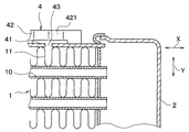
従来の熱交換器は、図4、5に示すように、多数のチューブ10と多数のコルゲートフィン11とを交互に積層してコア部1を構成している。また、コア部1におけるチューブ長手方向Xの両端部にタンク2、3を配置し、コア部1におけるチューブ積層方向Yの両端部にサイドプレート4を配置している。
As shown in FIGS. 4 and 5, the conventional heat exchanger forms a
この熱交換器は、熱交換器の構成部品を所定の熱交換器構造となるように仮組みした後、ワイヤーによりサイドプレート4の外側から熱交換器構造の組付体を締めつけて、組付体の仮組み状態を保持し、次に、この組付体をろう付け炉内に搬入し、ろう付け炉内にてろう材の融点まで加熱して組付体各部の接合箇所を一体ろう付けする。
In this heat exchanger, the components of the heat exchanger are temporarily assembled so as to have a predetermined heat exchanger structure, and then the assembly of the heat exchanger structure is tightened from the outside of the
ここで、サイドプレート4は、チューブ積層方向Yの両端部に位置するコルゲートフィン11を押さえて、コルゲートフィン11とチューブ10とのろう付け性を確保する機能を有している。
Here, the
ところで、この熱交換器をインタークーラとして用いた場合、近年の特に大型ディーゼルエンジンの排ガス規制強化に伴う過給気温度の上昇により、チューブ10とサイドプレート4に多大な温度差が生じ、熱膨張差によりチューブ根付(チューブ10とタンク2、3の接合部)に大きな応力が生じてチューブ10が破断する不具合が懸念される。
By the way, when this heat exchanger is used as an intercooler, a large temperature difference is generated between the
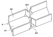
そこで、従来の熱交換器においては、熱膨張差によるチューブ10の破断を防止するために、チューブ10の伸びに応じてサイドプレート4も伸びるように、サイドプレート4の底板部41にスリット43を設け、サイドプレート4の側板部42に曲げ変形部421を設けている(例えば、特許文献1参照)。
しかしながら、上記の従来の熱交換器においては、底板部41と曲げ変形部421間にチューブ積層方向Yの隙間があるため、一体ろう付け前の組み付け時に底板部41が撓みやすく、またサイドプレート4全体がねじれやすく、その結果、コルゲートフィン11の座屈やコア部組付け寸法のくるいを招くという問題があった。
However, in the above-described conventional heat exchanger, since there is a gap in the tube stacking direction Y between the
本発明は上記点に鑑みて、フィンの座屈やコア部組付け寸法のくるいを抑制することを目的とする。 In view of the above points, an object of the present invention is to suppress the buckling of fins and the reduction of core assembly dimensions.
上記目的を達成するため、請求項1に記載の発明では、多数のチューブ(10)と多数のフィン(11)とが交互に積層配置されたコア部(1)と、コア部(1)におけるチューブ長手方向(X)の両端部に配置され、多数のチューブ(10)と連通するタンク(2、3)、コア部(1)におけるチューブ積層方向(Y)の両端部に配置され、両端がタンク(2、3)に結合されたサイドプレート(4)とを備える熱交換器において、サイドプレート(4)は、フィン(11)と接する底板部(41)と、底板部(41)からチューブ積層方向(Y)に延びる側板部(42)とを備え、側板部(42)は、曲げ変形により側板部(42)におけるチューブ長手方向(X)の伸縮を容易にする曲げ変形部(421)が形成され、底板部(41)は、曲げ変形部(421)に対応する位置に形成されたスリット(43)によりチューブ長手方向(X)に分割されており、さらに、底板部(41)におけるスリット(43)側の端部に、曲げ変形部(421)に向かって延びる爪部(411)が形成されており、爪部(411)のチューブ積層方向(Y)延長線上に、曲げ変形部(421)が位置していることを特徴とする。
In order to achieve the above object, in the invention according to
これによると、底板部が撓もうとしたりサイドプレート全体がねじれようとした場合、爪部が曲げ変形部に当たることにより底板部の撓みやサイドプレート全体のねじれが抑制ないしは防止されるため、フィンの座屈やコア部組付け寸法のくるいを抑制ないしは防止することができる。 According to this, when the bottom plate portion tries to bend or the entire side plate is twisted, the claw portion hits the bending deformation portion, so that the bending of the bottom plate portion and the entire side plate are suppressed or prevented. It is possible to suppress or prevent buckling and constriction of the core assembly size.
請求項2に記載の発明では、請求項1に記載の熱交換器において、曲げ変形部(421)における曲げ部分は曲面であることを特徴とする。
The invention according to claim 2 is characterized in that, in the heat exchanger according to
ところで、従来は曲げ変形部の曲げ部分は鋭角であったため、応力の集中によるサイドプレートの破断を招く恐れがあったが、請求項2に記載の発明によると、応力の集中を防ぐことができ、ひいてはサイドプレートの破断を防止することができる。 By the way, since the bending part of the bending deformation part was an acute angle conventionally, there was a possibility of causing the side plate to break due to the stress concentration. However, according to the invention of claim 2, the stress concentration can be prevented. As a result, breakage of the side plate can be prevented.
なお、上記各手段の括弧内の符号は、後述する実施形態に記載の具体的手段との対応関係を示すものである。 In addition, the code | symbol in the bracket | parenthesis of each said means shows the correspondence with the specific means as described in embodiment mentioned later.
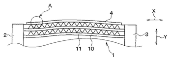
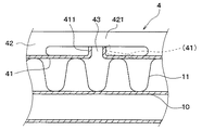
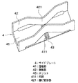
本発明の一実施形態について説明する。本実施形態は、本発明に係る熱交換器を、内燃機関に吸入される過給気を冷却するインタークーラに適用したものである。図1は一実施形態に係る熱交換器の正面図、図2は図1のA部を拡大して示す正面図、図3は図1のサイドプレート4の斜視図である。
An embodiment of the present invention will be described. In the present embodiment, the heat exchanger according to the present invention is applied to an intercooler that cools supercharged air sucked into an internal combustion engine. 1 is a front view of a heat exchanger according to an embodiment, FIG. 2 is an enlarged front view showing a portion A of FIG. 1, and FIG. 3 is a perspective view of a
図1に示すように、熱交換器は直方体形状のコア部1を備えており、コア部1は、交互に積層配置された多数のチューブ10と多数のコルゲートフィン11とで構成されている。
As shown in FIG. 1, the heat exchanger includes a rectangular
チューブ10は、真鍮製であり、車両に搭載された内燃機関に吸入される過給気が流通する流路を内部に有し、扁平状に形成されている。コルゲートフィン11は、銅製であり、コルゲート状に形成されて過給気と冷却風との熱交換を促進するものである。
The
コア部1におけるチューブ長手方向Xの両端部には、多数のチューブ10の各流路と連通するタンク2、3が配置されている。一方のタンク2は、真鍮製であり、圧縮されて高温になった過給気を多数のチューブ10に分配供給するものである。他方のタンク3は、真鍮製であり、冷却風との熱交換により冷却された過給気を集合回収して内燃機関に供給するものである。
Tanks 2, 3 communicating with the flow paths of the
コア部1におけるチューブ積層方向Yの両端部には、コルゲートフィン11とチューブ10とのろう付け性を確保するとともに、コア部1を補強するための、サイドプレート4が配置されている。サイドプレート4は、真鍮製であり、チューブ長手方向Xと平行な方向に延びてその両端がタンク2、3に接続されている。
At both ends of the
図2、図3に示すように、サイドプレート4は、断面がコの字状となるようにプレス成形され、それにより、コルゲートフィン11に接してコルゲートフィン11を押さえる底板部41と、底板部41の両側に位置し、底板部41からチューブ積層方向Yに延びる側板部42が形成されている。
As shown in FIGS. 2 and 3, the
側板部42には、曲げ変形により側板部42におけるチューブ長手方向Xの伸縮を容易にする曲げ変形部421が形成されている。この曲げ変形部421における曲げ部分は、緩やかな曲面になっている。そして、チューブ10とサイドプレート4に熱膨張差が生じた場合、変形部421の変形により熱膨張差を吸収して、チューブ10に作用する熱応力を抑制するようになっている。
The
底板部41は、曲げ変形部421に対応する位置に形成されたスリット43によりチューブ長手方向Xに分割されており、さらに、底板部41におけるスリット43側の端部に、曲げ変形部421における底板部41に対向する面に向かって延びる爪部411が形成されている。
The
曲げ変形部421と爪部411は自由状態では近接ないしは当接しており、図2に破線で示すような底板部41の変形、すなわち爪部411がコア部1から遠ざかる向きへ底板部41が変形することを防止するようになっている。
The
上記構成になる本実施形態の熱交換器は、次のようにして一体ろう付けされる。まず、熱交換器の構成部品であるチューブ10、コルゲートフィン11、タンク2、3、およびサイドプレート4を、所定の熱交換器構造となるように仮組みした後、ワイヤーによりサイドプレート4の外側から熱交換器の組付体を締めつけて、組付体の仮組み状態を保持する。次に、この組付体をろう付け炉内に搬入し、ろう付け炉内にてろう材の融点まで加熱して組付体各部の接合箇所を一体ろう付けする。
The heat exchanger of the present embodiment having the above configuration is integrally brazed as follows. First, after the
このろう付け工程において、ワイヤーによる締め付けを行う前の仮組み時点では、コア部1におけるチューブ長手方向Xの中間部がチューブ積層方向Y外側に向かって膨らむ傾向になり、サイドプレート4の底板部41が撓もうとする。
In this brazing process, at the time of temporary assembly before tightening with a wire, the intermediate portion in the tube longitudinal direction X of the
しかし、底板部が撓もうとした場合、爪部411が曲げ変形部421に当たることにより底板部411の撓みやサイドプレート4全体のねじれが抑制ないし防止される。したがって、コルゲートフィン11の座屈やコア部組付け寸法のくるいを抑制ないし防止することができる。
However, when the bottom plate portion is about to be bent, the
また、チューブ10とサイドプレート4に温度差が生じた場合には、曲げ変形部421が変形して熱膨張差が吸収されるため、チューブ10に作用する熱応力を抑制することができる。
Further, when a temperature difference occurs between the
しかも、曲げ変形部421における曲げ部分を緩やかな曲面にしているため、曲げ変形部421が変形する際の応力の集中を防ぐことができ、ひいてはサイドプレート4の破断を防止することができる。因みに、曲げ変形部421における曲げ部分の最大主応力を、従来の約1/3〜1/2にすることができる。
In addition, since the bending portion of the
(他の実施形態)
上記各実施形態では、本発明をインタークーラに適用したが、本発明はインタークーラ以外の熱交換器にも適用することができる。
(Other embodiments)
In each said embodiment, although this invention was applied to the intercooler, this invention is applicable also to heat exchangers other than an intercooler.
また、チューブ10、コルゲートフィン11、タンク2、3、およびサイドプレート4の各部品の材質は、鉄或いはアルミニウムなど他の金属材料を用いてもよい。
Further, as the material of each component of the
1…コア部、2、3…タンク、4…サイドプレート、10…チューブ、11…コルゲートフィン、41…底板部、42…側板部、43…スリット、411…爪部、421…曲げ変形部、X…チューブ長手方向、Y…チューブ積層方向。
DESCRIPTION OF
Claims (2)
前記コア部(1)におけるチューブ長手方向(X)の両端部に配置され、前記多数のチューブ(10)と連通するタンク(2、3)と、
前記コア部(1)におけるチューブ積層方向(Y)の両端部に配置され、両端が前記タンク(2、3)に結合されたサイドプレート(4)とを備える熱交換器において、
前記サイドプレート(4)は、前記フィン(11)と接する底板部(41)と、前記底板部(41)からチューブ積層方向(Y)に延びる側板部(42)とを備え、
前記側板部(42)は、曲げ変形により前記側板部(42)におけるチューブ長手方向(X)の伸縮を容易にする曲げ変形部(421)が形成され、
前記底板部(41)は、前記曲げ変形部(421)に対応する位置に形成されたスリット(43)によりチューブ長手方向(X)に分割されており、
さらに、前記底板部(41)における前記スリット(43)側の端部に、前記曲げ変形部(421)に向かって延びる爪部(411)が形成されており、前記爪部(411)のチューブ積層方向(Y)延長線上に、前記曲げ変形部(421)が位置していることを特徴とする熱交換器。 A core portion (1) in which a large number of tubes (10) and a large number of fins (11) are alternately stacked;
Tanks (2, 3) disposed at both ends of the tube longitudinal direction (X) in the core (1) and communicating with the multiple tubes (10),
In the heat exchanger comprising side plates (4) disposed at both ends in the tube stacking direction (Y) in the core portion (1) and having both ends coupled to the tanks (2, 3),
The side plate (4) includes a bottom plate portion (41) in contact with the fin (11), and a side plate portion (42) extending from the bottom plate portion (41) in the tube stacking direction (Y),
The side plate portion (42) is formed with a bending deformation portion (421) that facilitates expansion and contraction in the tube longitudinal direction (X) in the side plate portion (42) by bending deformation,
The bottom plate portion (41) is divided in the tube longitudinal direction (X) by a slit (43) formed at a position corresponding to the bending deformation portion (421),
Further, the bottom plate portion at an end portion of said slit (43) side of (41), the claw portions extending toward the bending deformation portion (421) (411) is formed, the tube of the claw portion (411) The heat exchanger , wherein the bending deformation portion (421) is positioned on an extension line in the stacking direction (Y) .
The heat exchanger according to claim 1, wherein the bent portion of the bending deformation portion (421) is a curved surface.
Priority Applications (4)
| Application Number | Priority Date | Filing Date | Title |
|---|---|---|---|
| JP2005045499A JP4604759B2 (en) | 2005-02-22 | 2005-02-22 | Heat exchanger |
| US11/358,796 US7389810B2 (en) | 2005-02-22 | 2006-02-20 | Displacement prevention device for the side plate of a heat exchanger |
| DE102006007759A DE102006007759A1 (en) | 2005-02-22 | 2006-02-20 | heat exchangers |
| CNB2006100086972A CN100462660C (en) | 2005-02-22 | 2006-02-21 | heat exchanger |
Applications Claiming Priority (1)
| Application Number | Priority Date | Filing Date | Title |
|---|---|---|---|
| JP2005045499A JP4604759B2 (en) | 2005-02-22 | 2005-02-22 | Heat exchanger |
Publications (2)
| Publication Number | Publication Date |
|---|---|
| JP2006234199A JP2006234199A (en) | 2006-09-07 |
| JP4604759B2 true JP4604759B2 (en) | 2011-01-05 |
Family
ID=36911413
Family Applications (1)
| Application Number | Title | Priority Date | Filing Date |
|---|---|---|---|
| JP2005045499A Expired - Fee Related JP4604759B2 (en) | 2005-02-22 | 2005-02-22 | Heat exchanger |
Country Status (4)
| Country | Link |
|---|---|
| US (1) | US7389810B2 (en) |
| JP (1) | JP4604759B2 (en) |
| CN (1) | CN100462660C (en) |
| DE (1) | DE102006007759A1 (en) |
Cited By (1)
| Publication number | Priority date | Publication date | Assignee | Title |
|---|---|---|---|---|
| US10302373B2 (en) | 2017-03-03 | 2019-05-28 | Denso International America, Inc | Heat exchanger |
Families Citing this family (14)
| Publication number | Priority date | Publication date | Assignee | Title |
|---|---|---|---|---|
| DE102004036019A1 (en) * | 2004-07-23 | 2006-02-16 | Behr Gmbh & Co. Kg | Radiator, in particular radiator for vehicles |
| US20080047689A1 (en) * | 2005-07-12 | 2008-02-28 | Denso Corporation | Heat exchanger |
| JP2008020085A (en) * | 2006-07-10 | 2008-01-31 | Denso Corp | Heat exchanger |
| JP5426563B2 (en) * | 2007-11-12 | 2014-02-26 | ベール ゲーエムベーハー ウント コー カーゲー | Exhaust gas cooler for automobile |
| US8844610B2 (en) * | 2008-09-18 | 2014-09-30 | Multistack, LLC | Double inlet heat exchanger |
| US20110024081A1 (en) * | 2009-07-29 | 2011-02-03 | Christian Riondet | End plate with area of weakness for a heat exchanger |
| EP2322890A1 (en) * | 2009-11-16 | 2011-05-18 | Thermex Ltd. | A marine heat exchanger |
| US8789805B2 (en) * | 2010-03-31 | 2014-07-29 | Denso International America, Inc. | Vibration stabilization system for multi-cooler |
| JP5009413B2 (en) * | 2010-12-22 | 2012-08-22 | シャープ株式会社 | Heat exchanger and air conditioner equipped with the same |
| US10359238B2 (en) | 2013-10-23 | 2019-07-23 | Modine Manufacturing Company | Heat exchanger and side plate |
| US10041742B2 (en) * | 2015-07-17 | 2018-08-07 | Denso International America, Inc. | Heat exchanger side plate with fin |
| US10429133B2 (en) * | 2016-08-04 | 2019-10-01 | Hanon Systems | Heat exchanger element with thermal expansion feature |
| CN212253807U (en) | 2020-02-18 | 2020-12-29 | 浙江盾安热工科技有限公司 | Micro-channel heat exchanger |
| DE102023200937A1 (en) * | 2023-02-06 | 2024-08-08 | Mahle International Gmbh | Thermal management module |
Family Cites Families (12)
| Publication number | Priority date | Publication date | Assignee | Title |
|---|---|---|---|---|
| FR2183375A5 (en) * | 1972-05-04 | 1973-12-14 | Chausson Usines Sa | |
| US4721069A (en) * | 1987-06-19 | 1988-01-26 | The Babcock & Wilcox Company | Termination for boiler casing expansion element |
| JPH0188183U (en) * | 1987-11-24 | 1989-06-09 | ||
| FR2711235B1 (en) * | 1993-10-11 | 1996-01-19 | Valeo Thermique Moteur Sa | Heat exchanger useful in particular as an oil radiator. |
| GB2303437A (en) * | 1995-06-12 | 1997-02-19 | Ford Motor Co | Stress relief in heat exchangers |
| JP3912836B2 (en) * | 1997-02-21 | 2007-05-09 | サンデン株式会社 | Heat exchanger |
| DE19753408B4 (en) * | 1997-12-02 | 2005-08-18 | Behr Gmbh & Co. Kg | Heat exchanger for a motor vehicle |
| JPH11325783A (en) * | 1998-05-20 | 1999-11-26 | Showa Alum Corp | Heat exchanger and method of manufacturing the same |
| US6328098B1 (en) * | 1998-11-10 | 2001-12-11 | Valeo Inc. | Side member for heat exchanger and heat exchanger incorporating side plate |
| JP2002147973A (en) * | 2000-08-30 | 2002-05-22 | Denso Corp | Duplex heat exchanger |
| US6412547B1 (en) * | 2000-10-04 | 2002-07-02 | Modine Manufacturing Company | Heat exchanger and method of making the same |
| DE10218048A1 (en) * | 2002-04-23 | 2003-11-13 | Behr Gmbh & Co | Heat exchanger, in particular heat exchanger module, for a motor vehicle |
-
2005
- 2005-02-22 JP JP2005045499A patent/JP4604759B2/en not_active Expired - Fee Related
-
2006
- 2006-02-20 DE DE102006007759A patent/DE102006007759A1/en not_active Withdrawn
- 2006-02-20 US US11/358,796 patent/US7389810B2/en not_active Expired - Fee Related
- 2006-02-21 CN CNB2006100086972A patent/CN100462660C/en not_active Expired - Fee Related
Cited By (1)
| Publication number | Priority date | Publication date | Assignee | Title |
|---|---|---|---|---|
| US10302373B2 (en) | 2017-03-03 | 2019-05-28 | Denso International America, Inc | Heat exchanger |
Also Published As
| Publication number | Publication date |
|---|---|
| CN100462660C (en) | 2009-02-18 |
| US7389810B2 (en) | 2008-06-24 |
| CN1825044A (en) | 2006-08-30 |
| US20060185824A1 (en) | 2006-08-24 |
| JP2006234199A (en) | 2006-09-07 |
| DE102006007759A1 (en) | 2006-11-16 |
Similar Documents
| Publication | Publication Date | Title |
|---|---|---|
| JP4604759B2 (en) | Heat exchanger | |
| JP6547576B2 (en) | Heat exchanger | |
| US20080000626A1 (en) | Heat exchanger | |
| JP5029166B2 (en) | Heat exchanger | |
| US6918432B2 (en) | Heat exchanger | |
| US20130220585A1 (en) | Tube for heat exchanger | |
| US20060144579A1 (en) | Heat exchanger | |
| JP2008249252A (en) | Heat exchanging device | |
| US6892804B2 (en) | Heat exchanger | |
| JP2005106431A (en) | Heat exchanger module | |
| JP5970924B2 (en) | Heat exchanger with tubes | |
| JP2006189205A (en) | Heat exchanger | |
| WO2017013918A1 (en) | Heat exchanger | |
| US8136578B2 (en) | Heat exchanger for EGR-gas | |
| JP2006284107A (en) | Heat exchanger | |
| JP2003130577A (en) | Heat exchanger and manufacturing method for it | |
| JP4239840B2 (en) | Mouth expansion jig for heat exchanger tubes | |
| JP2006207966A (en) | Heat exchanger | |
| JP4222195B2 (en) | Heat exchanger | |
| JP5084735B2 (en) | Enhanced manifold for heat exchanger header tank and header tank with such manifold | |
| JP2003336993A (en) | Heat exchanger | |
| JP2006162136A (en) | Duplex heat exchanger | |
| JP2019184166A (en) | Heat exchanger | |
| JP7386789B2 (en) | heat exchanger core | |
| JP2005156067A (en) | Heat exchanger module |
Legal Events
| Date | Code | Title | Description |
|---|---|---|---|
| A621 | Written request for application examination |
Free format text: JAPANESE INTERMEDIATE CODE: A621 Effective date: 20070510 |
|
| A977 | Report on retrieval |
Free format text: JAPANESE INTERMEDIATE CODE: A971007 Effective date: 20100423 |
|
| A131 | Notification of reasons for refusal |
Free format text: JAPANESE INTERMEDIATE CODE: A131 Effective date: 20100511 |
|
| A521 | Request for written amendment filed |
Free format text: JAPANESE INTERMEDIATE CODE: A523 Effective date: 20100701 |
|
| TRDD | Decision of grant or rejection written | ||
| A01 | Written decision to grant a patent or to grant a registration (utility model) |
Free format text: JAPANESE INTERMEDIATE CODE: A01 Effective date: 20100907 |
|
| A01 | Written decision to grant a patent or to grant a registration (utility model) |
Free format text: JAPANESE INTERMEDIATE CODE: A01 |
|
| A61 | First payment of annual fees (during grant procedure) |
Free format text: JAPANESE INTERMEDIATE CODE: A61 Effective date: 20100920 |
|
| FPAY | Renewal fee payment (event date is renewal date of database) |
Free format text: PAYMENT UNTIL: 20131015 Year of fee payment: 3 |
|
| LAPS | Cancellation because of no payment of annual fees |