JP4604748B2 - Brake control device for vehicle - Google Patents
Brake control device for vehicle Download PDFInfo
- Publication number
- JP4604748B2 JP4604748B2 JP2005030820A JP2005030820A JP4604748B2 JP 4604748 B2 JP4604748 B2 JP 4604748B2 JP 2005030820 A JP2005030820 A JP 2005030820A JP 2005030820 A JP2005030820 A JP 2005030820A JP 4604748 B2 JP4604748 B2 JP 4604748B2
- Authority
- JP
- Japan
- Prior art keywords
- braking
- vehicle
- predetermined
- braking force
- amount
- Prior art date
- Legal status (The legal status is an assumption and is not a legal conclusion. Google has not performed a legal analysis and makes no representation as to the accuracy of the status listed.)
- Expired - Fee Related
Links
Images


Description
この発明は、車両の車輪に付与する制動力を制御する車両の制動制御装置に関するものである。 The present invention relates to a vehicle braking control device that controls braking force applied to a vehicle wheel.
従来、車両の駆動力あるいは動力源の出力トルクと関連させて車両の制動力を制御することにより、例えば車両の登坂路での発進時に、車両の後退を防止して、スムーズに発進させることがおこなわれている。その一例として、運転者の進行希望方向と実進行方向とが逆方向の場合に、車両の実進行方向と同じ方向に回転する車輪に対して制動力を作用させる制御が実行され、その制御が所定時間を超えて継続された場合にその制御を終了させるように構成された車両走行状態制御装置に関する発明が、特許文献1に記載されている。 Conventionally, by controlling the braking force of the vehicle in relation to the driving force of the vehicle or the output torque of the power source, for example, when the vehicle starts on an uphill road, the vehicle can be prevented from moving backward to start smoothly. It is done. As an example, when the driver's desired traveling direction and the actual traveling direction are opposite to each other, a control for applying a braking force to a wheel rotating in the same direction as the actual traveling direction of the vehicle is executed. Patent Document 1 discloses an invention relating to a vehicle running state control device configured to end the control when the control is continued beyond a predetermined time.
この特許文献1に記載されている発明は、運転者の進行希望方向と実進行方向とが逆方向であること、すなわち車両が坂路下方へずり落ちていることが検知された場合に、ずり落ち方向に回転している車輪に対して制動力が付与されるように制御される。そして、その制動力を付与する制御が所定時間を超えて継続された場合に、その制御が終了される。そのため、坂路における車両のずり落ち速度を緩和させることができ、また運転者に適切なブレーキ・アクセル操作を促すとともに、制動装置が長時間動作することを回避して制動装置の保護を図ることができる、とされている。 The invention described in this Patent Document 1 is that when it is detected that the driver's desired travel direction and the actual travel direction are opposite, that is, that the vehicle is slipping down the slope, Control is performed so that braking force is applied to the wheels rotating in the direction. Then, when the control for applying the braking force is continued beyond a predetermined time, the control is terminated. Therefore, it is possible to mitigate the vehicle falling speed on the slope, to prompt the driver to perform appropriate brake / accelerator operation, and to prevent the braking device from operating for a long time, thereby protecting the braking device. It can be done.
また、特許文献2には、一連のブレーキ制動操作による制御信号、すなわちクラッチペダルスイッチからのクラッチ操作信号、アクセル操作スイッチからのアクセル操作信号、ブレーキスイッチからのブレーキ操作信号、前後進シフトスイッチからのシフト信号などの制御信号と、車速センサからの車両停止信号とが検出された場合に、ブレーキホイールシリンダの液圧を保持して前後輪を制動ロックした状態を保ち、その状態から、クラッチペダルを踏み込み、シフトレバーを所定位置にシフトし、アクセルペダルを踏み込む一連の発進操作による制御信号が検出された場合にブレーキホイールシリンダの液圧の保持が解除されるように構成されたブレーキ液圧制御装置に関する発明が記載されている。
そして、特許文献3には、運転者がブレーキペダルからアクセルペダルに踏み替えたときに車両が移動するのを防止する、いわゆるヒルホールド制御を実行する装置であって、アイドルストップ状態での車両停止中であり、かつマスタシリンダ圧力が許可閾値以下の場合にヒルホールド制御が実行され、そのヒルホールド制御の実行中に運転者が再度ブレーキペダルを踏み込んだ場合にヒルホールドが解除されるように構成されたブレーキ制御装置に関する発明が記載されている。
上記の各特許文献に記載されている各発明では、制御の開始条件として、車両が坂路下方へずり落ちていることが検出された場合、あるいはブレーキ制動操作信号と車両停止信号とが検出された場合、あるいはアイドルストップ状態での車両停止中にマスタシリンダ圧力が所定値以下の場合に、坂路での発進時などにおける、車輪に対して制動力を付与する制御、あるいはブレーキホイールシリンダの液圧を保持する制御、あるいはヒルホールド制御など、すなわち坂路での発進時に車両の制動力を保持して車両の下降を防止し発進を補助する、いわゆる制動力保持制御が実行される。 In each invention described in each of the above patent documents, as a control start condition, it is detected that the vehicle has slipped down the slope, or a brake braking operation signal and a vehicle stop signal are detected. If the master cylinder pressure is less than the predetermined value when the vehicle is stopped in the idling stop state, the control for applying the braking force to the wheel at the start of the slope or the hydraulic pressure of the brake wheel cylinder Control for holding, hill hold control, or the like, that is, so-called braking force holding control for holding the braking force of the vehicle when starting on a slope to prevent the vehicle from descending and assisting starting is executed.
したがって、上記の各特許文献に記載されている各発明では、上記のような制御の開始条件が成立した場合に制動力保持制御が実行されるようになっており、例えば乗員の意志によって、任意に制動力保持制御を開始させる場合については、いずれの発明においても考慮されておらず、この点に関して未だ改良の余地があった。 Therefore, in each invention described in each of the above patent documents, the braking force holding control is executed when the control start condition as described above is satisfied. The case where the braking force holding control is started is not considered in any of the inventions, and there is still room for improvement in this respect.
この発明は上記の技術的課題に着目してなされたものであり、乗員の意志による簡単な操作によって、車両の制動力を保持する制御を実行することのできる制御装置を提供することを目的とするものである。 This invention was made paying attention to said technical subject, and it aims at providing the control apparatus which can perform control which hold | maintains the braking force of a vehicle by simple operation by a passenger | crew's will. To do.
上記の目的を達成するために、請求項1の発明は、乗員の制動操作に基づいて動作する所定の制動装置により車輪に付与する制動力を制御する車両の制動制御装置において、前記車両の車速を検出する車速検出手段と、前記所定の制動装置における前記乗員の制動操作量を検出する制動操作検出手段と、前記車速検出手段により前記車速が所定車速以下になったことが検出された場合に、前記制動操作検出手段により前記所定の制動装置における前記乗員の第1の制動操作量が検出され、その後、その第1の制動操作量に予め定められた所定量を加えた値よりも大きい前記所定の制動装置における前記乗員の第2の制動操作量が検出された場合に、前記制動力を保持する制動力保持手段と、前記第1の制動操作量の値が予め定められた所定の上限値以上の場合に、前記所定量の値を小さくする追加制動操作量変更手段とを備えていることを特徴とする制御装置である。 In order to achieve the above object, a first aspect of the present invention provides a vehicle braking control device for controlling a braking force applied to a wheel by a predetermined braking device that operates based on a braking operation of an occupant. Vehicle speed detecting means for detecting the vehicle speed, braking operation detecting means for detecting the amount of braking operation of the occupant in the predetermined braking device, and when the vehicle speed detecting means detects that the vehicle speed is below a predetermined vehicle speed. the first amount of braking operation of the occupant in the predetermined brake device by a braking operation detecting means is detected, greater then be Ri by predetermined a predetermined amount of value added to the first amount of braking operation when the second brake operation amount of the occupant in the predetermined braking device is detected, the braking force holding means for holding the braking force, the value of the first braking operation amount predetermined predetermined When the above limit value, a control apparatus characterized by comprising an additional brake operation amount change means for reducing the value of the predetermined amount.
また、請求項2の発明は、請求項1の発明において、前記制動力保持手段により前記制動力の保持がおこなわれた際に前記所定の制動装置に対する所定の制動解除操作が所定時間継続された場合に、前記制動力の保持を解除する制動力保持解除手段を更に備えていることを特徴とする制御装置である。
The invention of
さらに、請求項3の発明は、請求項2の発明において、前記車両が降坂路での下降状態であることを検出する下降状態検出手段を更に備え、前記制動力保持解除手段は、前記制動力保持手段により前記制動力の保持がおこなわれた際に、前記下降状態検出手段により前記車両が下降状態であることが検出され、かつ前記制動操作検出手段により前記制動操作量が検出されなくなった後に再び前記制動操作量が検出された場合に、前記制動力の保持を解除する手段を含むことを特徴とする制御装置である。
Further, the invention of
またさらに、請求項4の発明は、請求項1ないし3のいずれかの発明において、前記所定の制動装置が、前記乗員の制動操作に応じて圧力を発生させるマスタシリンダと、その圧力を分配して前記車輪に制動力を付与するホイールシリンダとを有し、前記制動操作量が、前記所定の制動装置のマスタシリンダ圧に基づいて決まる物理量であることを特徴とする制御装置である。
Furthermore, the invention of
請求項1の発明によれば、乗員の制動操作により所定の制動装置が動作されることによって、車両が制動されて車速が所定車速以下になると、その際の乗員の制動操作による所定の制動装置の制動操作量が第1の制動操作量として検出され、その後、乗員の制動操作が追加されることにより、第1の制動操作量よりも大きな制動操作量が第2の制動操作量として検出された場合に、所定の制動装置により車輪に付与された制動力が保持される。例えば、車速が0km/h以下になり停止したことが検出されると、その際の乗員の制動操作量が第1の制動操作量として検出される。そして、車両停止後に乗員の制動操作が追加された場合、すなわち第1の制動操作量よりも大きい第2の制動操作量が検出された場合に、車両の制動力を保持して車両の移動を防止もしくは抑制する、いわゆる制動力保持制御が開始される。そのため、乗員の制動操作の追加などの、乗員の意志による簡単な制動操作によって制動力保持制御を開始させることができ、例えば坂路での発進時に車両の下降を防止し、もしくは抑制して発進を補助することができる。 According to the first aspect of the present invention, when the vehicle is braked and the vehicle speed becomes equal to or lower than the predetermined vehicle speed by operating the predetermined braking device by the occupant braking operation, the predetermined braking device by the occupant braking operation at that time The braking operation amount is detected as the first braking operation amount, and then the braking operation amount greater than the first braking operation amount is detected as the second braking operation amount by adding the occupant's braking operation. In this case, the braking force applied to the wheels by the predetermined braking device is maintained. For example, when it is detected that the vehicle speed is 0 km / h or less and the vehicle is stopped, the braking operation amount of the occupant at that time is detected as the first braking operation amount. When a braking operation of an occupant is added after the vehicle stops, that is, when a second braking operation amount larger than the first braking operation amount is detected, the vehicle is kept moving while maintaining the braking force. The so-called braking force holding control for preventing or suppressing is started. For this reason, the braking force holding control can be started by a simple braking operation at the will of the occupant, such as the addition of a braking operation by the occupant. Can assist.
また、乗員の制動操作による第1の制動操作量によって車両が制動された後、乗員の制動操作の追加による、前記第1の制動操作量に予め定められた適宜の所定量が加えられた値よりも大きい第2の制動操作量が検出された場合に、制動力保持制御が開始される。そのため、乗員の意志による簡単な制動操作によって、確実に制動力保持制御を開始させることができる。 Further, after the vehicle has been braked by the first brake operating amount by the braking operation of multiplication-membered, by addition of an occupant of a braking operation, a predetermined amount of an appropriate predetermined for the first braking operation amount added When the second braking operation amount larger than the value is detected, the braking force holding control is started. Therefore, the braking force holding control can be surely started by a simple braking operation at the will of the occupant.
さらに、乗員の制動操作による第1の制動操作量の値が予め定められた所定の上限値以上の場合に、前記第2の制動操作量が検出される際に用いられる閾値の基となる前記所定量の値が小さくされる。そのため、予め定められた所定の上限値以上の第1の制動操作量が検出される程度の、大きな制動操作がおこなわれた場合においても、乗員の意志による簡単な制動操作によって、より確実に制動力保持制御を開始させることができる。 Further, if the value of the first amount of braking operation by the braking operation of multiplication members is equal to or larger than a predetermined upper limit value set in advance, a threshold value of the group used in the second amount of braking operation is detected The predetermined amount is reduced. Therefore, even when a large braking operation is performed to the extent that a first braking operation amount equal to or greater than a predetermined upper limit value is detected, the braking operation is more reliably performed by a simple braking operation based on the occupant's will. Power holding control can be started.
またさらに、請求項2の発明によれば、制動力保持制御が実行されている際、例えばブレーキペダルの解放操作などの所定の制動装置に対する所定の制動解除操作が所定時間継続された場合に、制動力保持制御が終了されて制動力の保持が解除される。そのため、乗員に適切な制動操作もしくは発進操作をおこなうことを促すとともに、所定の制動装置が動作されて制動力が保持されている状態が長時間に及ぶことを回避して所定の制動装置を保護することができる。
Furthermore, according to the invention of
一方、請求項3の発明によれば、制動力保持制御の実行中に車両が降坂路において前進もしくは後退して下降する車両の下降状態が検出された場合に、前記制動操作量が検出されなくなり、その後、再び前記制動操作量が検出された場合、すなわち、制動力保持制御の実行中に車両が下降状態であることが検出された場合に、例えば所定の制動装置に対する所定の制動解除操作がおこなわれ前記制動操作量が検出されなくなった後に、再び乗員の制動操作による前記制動操作量が検出された場合に、制動力保持制御が終了されて制動力の保持が解除される。そのため、降坂路において車両が停止し、制動力保持制御が実行された際には、乗員の制動操作が再びおこなわれた場合に制動力の保持が解除されるので、降坂路での急発進などを回避することができる。
On the other hand, according to the invention of
そして、請求項4の発明によれば、例えば乗員のブレーキペダルの踏み込み操作などに応じて圧力を発生させるマスタシリンダのマスタシリンダ圧に基づいて、前記第1の制動操作量および前記第2の制動操作量などの前記制動操作量が検出される。そのため、例えば乗員のブレーキペダルの追加踏み込み操作などの、乗員の意志による簡単な制動操作によって制動力保持制御を開始させることができる。 According to the fourth aspect of the present invention, the first braking operation amount and the second braking operation are performed based on the master cylinder pressure of the master cylinder that generates pressure in response to , for example, an occupant's depression operation of the brake pedal. The braking operation amount such as the operation amount is detected. Therefore, for example, the braking force holding control can be started by a simple braking operation by the occupant's will, such as an additional depression operation of the occupant's brake pedal .
この発明の実施例を図面に基づいて説明する。まず、この発明を適用した車両の駆動系を図7に示す。図7は、この発明を適用した車両Veが、例えば四輪駆動車両Veである例を示している。図7に示す車両Veにおいて、動力源1の出力側には、動力源1の回転出力を変速する変速機2が配置され、その変速機2の出力側には、変速機2から伝達される駆動力を前輪側の駆動軸3と後輪側の駆動軸4とに分配するトランスファ(副変速機)5が設けられている。
An embodiment of the present invention will be described with reference to the drawings. First, FIG. 7 shows a vehicle drive system to which the present invention is applied. FIG. 7 shows an example in which the vehicle Ve to which the present invention is applied is, for example, a four-wheel drive vehicle Ve. In the vehicle Ve shown in FIG. 7, a
動力源1としては、例えば、内燃機関または電動機の少なくとも一方を用いることができる。電動機としては、例えば電気エネルギを運動エネルギに変換する力行機能と運動エネルギを電気エネルギに変換する回生機能とを有するモータ・ジェネレータを用いることが可能である。この実施例では、動力源1として、ガソリンエンジンやディーゼルエンジンあるいは天然ガスエンジンなどのエンジン1が用いられている場合について説明する。また、変速機2としては、手動変速機、あるいは自動変速機、あるいは無段変速機などの各種の変速機を用いることが可能である。
As the power source 1, for example, at least one of an internal combustion engine or an electric motor can be used. As the electric motor, for example, a motor generator having a power running function for converting electric energy into kinetic energy and a regenerative function for converting kinetic energy into electric energy can be used. In this embodiment, a case where an engine 1 such as a gasoline engine, a diesel engine, or a natural gas engine is used as the power source 1 will be described. Further, as the
トランスファ5は、変速機2の回転出力を減速することなく駆動軸3,4へ伝達する高速側のハイギヤ列と、変速機2の回転出力をさらに減速して駆動軸3,4へ伝達する低速側のローギヤ列との二つのギヤ列を備えており、トランスファ5用のシフトレバー(図示せず)の操作によって、ハイギヤ列とローギヤ列とを選択的に切り換えて使用することができるように構成されている。また、このトランスファ5は、その内部に差動装置(センターデファレンシャル)(図示せず)を備えており、車両Veの旋回時に生じる前輪と後輪との回転差を吸収することができるように構成されている。
The
前輪側の駆動軸3は、フロントデファレンシャル6を介して左右の前輪駆動軸7,8に連結されていて、前輪駆動軸7,8には、左右前輪となる車輪9,10が連結されている。また、後輪側の駆動軸4は、リヤデファレンシャル11を介して左右の後輪駆動軸12,13に連結されていて、後輪駆動軸12,13には、左右後輪となる車輪14,15が連結されている。このような各機構により形成される動力伝達系統を介して、エンジン1の出力トルクが各車輪9,10,14,15に伝達される構成となっている。
The front wheel
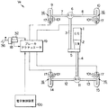
そして、各車輪9,10,14,15には、制動装置16がそれぞれに設けられている。また、制動装置16を構成するホイールシリンダ17と、マスタシリンダ18とを接続する作動液の液圧系には、乗員のブレーキ操作(制動操作)とは別にホイールシリンダ17内の液圧を増減し、各車輪9,10,14,15に付与する制動力を制御するブレーキアクチュエータ19が設けられている。
Each
マスタシリンダ18は、例えばブレーキペダルの踏み込み操作などの、乗員のブレーキ操作に応じて、作動液に液圧を発生させる役目を果たしている。一方、ホイールシリンダ17は、乗員のブレーキ操作によってマスタシリンダ18から圧送される作動液の液圧により、各車輪9,10,14,15に制動力を付与するように動作する構成となっている。なお、ディスクブレーキが採用される場合には、そのディスクブレーキのキャリパに備えられているシリンダが上記のホイールシリンダ17に相当し、同様に作用させることができる。
The
図8に、ブレーキアクチュエータ19の構成を概略的に示す。なお、ブレーキアクチュエータ19は、各車輪9,10,14,15の各制動装置16毎に、独立して液圧を制御することが可能なように構成されていて、図8には、各車輪9,10,14,15のうちの一つの車輪に関するブレーキアクチュエータ19の構成を代表的に示している。したがって他の車輪についても同様の構成となっている。
FIG. 8 schematically shows the configuration of the
ブレーキアクチュエータ19を構成する液圧系統には、モータ20によって回転駆動される液圧ポンプ21が設けられている。この液圧ポンプ21は、制動力を制御する際の液圧源として機能し、液圧ポンプ21の吐出口21aは、管路22を介して、遮断弁23と保持弁24との間の管路25に接続されている。なお、液圧ポンプ21の吐出口21a側には、液圧ポンプ21の吐出方向とは逆方向の作動液の流れを阻止する逆止弁26が設けられている。
The hydraulic system constituting the
一方、液圧ポンプ27の吸入口21bは、管路27を介してリザーバ28に接続されていて、管路27には、液圧ポンプ21の吸入方向とは逆方向の作動液の流れを阻止する逆止弁29,30が設けられている。この逆止弁29,30の間の管路27は、管路31を介してリザーバタンク32に接続されていて、リザーバタンク32内の作動液が、管路27を介して液圧ポンプ21に吸い込まれるように構成されている。また、管路31の途中には、この管路31を開閉させる、ノーマルクローズ形(通電時に開弁する形式)の吸込弁33が設けられている。
On the other hand, the suction port 21b of the
前述のマスタシリンダ18とホイールシリンダ17とを接続する管路25には、ノーマルオープン形(通電時に閉弁する形式)の遮断弁23が設けられており、作動液の液圧制御が実行される際に閉弁されてマスタシリンダ18とホイールシリンダ17との間の管路25を遮断するように構成されている。また、遮断弁23よりもホイールシリンダ17側の管路25には、ノーマルオープン形の保持弁24が設けられており、この保持弁24が閉弁されることにより、保持弁24からホイールシリンダ17側の液圧系を閉塞状態にするように、すなわち保持弁24からホイールシリンダ17側の液圧系の液圧を保持するように構成されている。
The
したがって、保持弁24を閉弁状態に制御することにより、保持弁24からホイールシリンダ17側の液圧系の液圧、すなわちブレーキ液圧を保持することができ、その結果、各車輪9,10,14,15に付与された制動力をそれぞれ保持することができる。
Therefore, by controlling the holding
そして、保持弁24とホイールシリンダ17との間の管路25は、管路34によってリザーバ28に接続されている。この管路34には、ノーマルクローズ形の減圧弁35が設けられており、ON/OFFの2値状態の駆動制御信号によって、減圧弁35をduty駆動させることにより、管路34の連通状態を変化させることができる。
The
したがって、減圧弁35の開閉状態を制御することにより、管路34の連通状態を変化させ、保持弁24からホイールシリンダ17側の液圧系の液圧(ブレーキ液圧)を変化させることができる。例えば上記のように、ブレーキ液圧を保持していた状態、すなわち各車輪9,10,14,15に付与された制動力をそれぞれ保持していた状態から、減圧弁35を開弁状態に制御して管路34を連通状態にし、ブレーキ液圧を減圧させることによって、各車輪9,10,14,15に付与された制動力の保持状態を解除することができる。
Therefore, by controlling the open / close state of the
このように、液圧ポンプ21および各種の弁装置等によって構成されるブレーキアクチュエータ19は、電子制御装置100によってその動作が制御される。すなわち、電子制御装置100により、ブレーキアクチュエータ19の動作を制御し、制動装置16のホイールシリンダ17内の液圧が増減制御される。したがって、電子制御装置100から出力される信号に基づいて、各車輪9,10,14,15に設けられた制動装置16をそれぞれ制御することができる。
As described above, the operation of the
図9に、電子制御装置100の構成を概略的に示す。電子制御装置100には、各車輪9,10,14,15の回転速度をそれぞれ検出する車輪速センサ101、シフトレバーのシフトポジションを検知するシフトポジションセンサ102、ブレーキペダル36の踏み込み量(踏み込み角度)を検出するブレーキペダルセンサ103、アクセルペダル(図示せず)の踏み込み量を検出するアクセルペダルセンサ104、トランスファ5用のシフトレバーによって選択されたギヤ列を検知する選択ギヤ列検知センサ105、車両Veの前後方向の加速度を検出する前後加速度センサ106、路面の傾斜角を検出する傾斜角センサ107、そしてマスタシリンダ18で発生させされる液圧を検出するマスタシリンダ圧センサ108などの各種センサが設けられており、それらの各センサの出力信号が電子制御装置100に入力されるように構成されている。
FIG. 9 schematically shows the configuration of the
また、電子制御装置100には、各種のデータが記憶されており、電子制御装置100に入力される信号、および記憶されているデータに基づいて、電子制御装置100から、ブレーキアクチュエータ19を制御する信号が出力されるように構成されている。
Various types of data are stored in the
ここで、上記の車輪速センサ101により検出される各車輪9,10,14,15の回転速度に基づいて、すなわち各車輪9,10,14,15の回転速度の検出値を基に電子制御装置100で演算処理することによって、車両Veの車速を算出することができる。したがって、電子制御装置100および車輪速センサ101は、この発明における車速検出手段として機能する。
Here, electronic control is performed based on the rotational speeds of the
また、上記のブレーキペダルセンサ103により検出されるブレーキペダル36の踏み込み量(踏み込み角度)、あるいはマスタシリンダ圧センサ108により検出されるマスタシリンダ圧に基づいて、すなわちブレーキペダル36の踏み込み量(踏み込み角度)、あるいはその踏み込み量(踏み込み角度)に応じて圧力が発生させられるマスタシリンダ圧を基に電子制御装置100で演算処理することによって、乗員の制動操作量を算出することができる。したがって、電子制御装置100、ブレーキペダルセンサ103、マスタシリンダ圧センサ108は、この発明における制動操作検出手段として機能する。
Further, based on the depression amount (depression angle) of the
さらに、上記の傾斜角センサ107あるいは車輪速センサ101あるいは前後加速度センサ106の検出値を基に求められる路面の傾斜角と、シフトポジションセンサ102により検知されるシフトポジションから求められる車両の進行方向と、車輪速センサ101あるいは前後加速度センサ106の検出値から求められる車両の進行状態とに基づいて、すなわちそれらの検出値などを基に電子制御装置100で演算処理することによって、車両Veが降坂路において前進もしくは後退して下降する車両の下降状態を検出することができる。したがって、電子制御装置100、傾斜角センサ107、車輪速センサ101、前後加速度センサ106は、この発明における下降状態検出手段として機能する。
Further, the road surface inclination angle obtained from the detection value of the
なお、前述の各車輪9,10,14,15の制動装置16を構成するホイールシリンダ17、マスタシリンダ18、ブレーキアクチュエータ19、それらを接続する液圧系、そして電子制御装置100などにより構成される制動装置が、この発明における所定の制動装置に相当する。
The
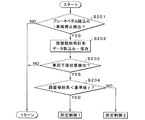
前述したように、この発明は、乗員の意志による簡単な操作によって車両Veの制動力を保持することのできる制御装置を提供することを目的としていて、そのために、この発明の制御装置は以下の制御を実行するように構成されている。図1は、その第1制御例を説明するためのフローチャートであって、このフローチャートで示されるルーチンは、所定の短時間毎に繰り返し実行される。図1において、先ず、乗員の意志による制動操作によって、車両Veが停止した状態であるか否かが判断される(ステップS101)。 As described above, an object of the present invention is to provide a control device that can maintain the braking force of the vehicle Ve by a simple operation according to the will of the occupant. For this purpose, the control device of the present invention includes the following: It is configured to perform control. FIG. 1 is a flowchart for explaining the first control example, and the routine shown in this flowchart is repeatedly executed every predetermined short time. In FIG. 1, first, it is determined whether or not the vehicle Ve is in a stopped state by a braking operation at the will of the occupant (step S101).
具体的には、乗員の意志による制動操作、例えば乗員によるブレーキペダル36の踏み込み操作がおこなわれ、その際にブレーキペダルセンサ103によって検出されるブレーキペダル36の踏み込み量(踏み込み角度)、あるいはブレーキペダル36の踏み込み量(踏み込み角度)に応じて圧力を発生させるマスタシリンダ18のマスタシリンダ圧などに基づいて各車輪9,10,14,15に制動力が付与されて、その制動力により車両Veが停止した状態であるか否かが判断される。なお、この場合の車両Veの停止状態の判断は、例えば各車輪9,10,14,15の回転速度をそれぞれ検出する車輪速センサ101の検出結果が全て所定車速(例えばほぼ0km/h)以下であることにより判断することができる。
Specifically, a braking operation at the will of the occupant, for example, a depression operation of the
車両Veが停止状態でないこと、例えば各車輪速センサ101の検出結果の少なくともいずれか一つが所定車速以下でないことにより、このステップS101で否定的に判断された場合は、以降の制御は実行されずに、このルーチンを一旦終了する。
If the vehicle Ve is not in a stopped state, for example, if at least one of the detection results of the
これに対して、車両Veが停止状態にあることにより、ステップS101で肯定的に判断された場合は、ステップS102へ進み、制動操作時すなわちブレーキペダル36の踏み込み操作時のブレーキ液圧が下限設定値Lよりも大きいか否かが判断される。この場合のブレーキ液圧の値は、例えばブレーキペダルセンサ103によって検出されるブレーキペダル36の踏み込み量、あるいはマスタシリンダ圧センサ108によって検出されるマスタシリンダ圧などの検出値に基づいて求めることができる。また、下限設定値Lとは、この制御において有効な制動操作を判断するために定められた下限の閾値である。
On the other hand, if the vehicle Ve is in a stopped state and the determination is affirmative in step S101, the process proceeds to step S102, where the brake fluid pressure during the braking operation, that is, during the depression of the
したがって、ブレーキペダル36の踏み込み操作時のブレーキ液圧が下限設定値L以下であることにより、このステップS102で否定的に判断された場合は、以降の制御は実行されずに、このルーチンを一旦終了する。なお、ここでのブレーキペダル36の踏み込み操作時のブレーキ液圧とは、前述のように、マスタシリンダ18から各ホイールシリンダ17へ供給される液圧のことであり、したがって乗員の制動操作に応じて発生させられるマスタシリンダ圧に基づいて設定される物理量として表すことができ、この発明における制動操作量に相当する。
Therefore, if the brake fluid pressure at the time of depressing the
一方、ブレーキペダル36の踏み込み操作時のブレーキ液圧が下限設定値Lよりも大きいことにより、ステップS102で肯定的に判断された場合には、ステップS103へ進み、ブレーキペダル36の踏み込み操作時のブレーキ液圧の最大値が上限設定値Uよりも小さいか否かが判断される。上限設定値Uとは、後述のステップS104もしくはS105で、ブレーキペダル36の踏み込み操作時のブレーキ液圧、すなわちブレーキペダル36の踏み込み操作時の制動操作量の大きさに応じて設定される所定量を、所定量αもしくはその所定量αよりも小さい所定量βに設定する際の判断閾値である。
On the other hand, when the brake fluid pressure at the time of depressing operation of the
具体的には、上限設定値Uは、制動操作量が大きい場合に小さな所定量を設定し、制動操作量が小さい場合に大きな所定量を設定する際の判断閾値である。より具体的には、後述の第2の制動操作量を検出する際に用いられる所定量として、ブレーキペダル36の踏み込み操作時のブレーキ液圧の最大値が上限設定値Uよりも小さい場合は、所定量αが設定され、ブレーキペダル36の踏み込み操作時のブレーキ液圧の最大値が上限設定値U以上の場合には、所定量αよりも小さい所定量βが設定される。したがって、この上限設定値Uは、この発明における予め定められた所定の上限値に相当する。
Specifically, the upper limit set value U is a determination threshold when a small predetermined amount is set when the braking operation amount is large and a large predetermined amount is set when the braking operation amount is small. More specifically, when the maximum value of the brake fluid pressure when the
したがって、ブレーキペダル36の踏み込み操作時のブレーキ液圧の最大値が上限設定値Uよりも小さいことにより、このステップS103で肯定的に判断された場合は、ステップS104へ進み、ブレーキペダル36の追加踏み込み操作によるブレーキ液圧の増加量が、予め定められた所定量αよりも大きいか否かが判断される。
Therefore, if the maximum value of the brake fluid pressure during the depression operation of the
一方、ブレーキペダル36の踏み込み操作時のブレーキ液圧の最大値が上限設定値U以上であることにより、ステップS103で否定的に判断された場合は、ステップS105へ進み、ブレーキペダル36の追加踏み込み操作によるブレーキ液圧の増加量が、予め定められた所定量βよりも大きいか否かが判断される。
On the other hand, when the maximum value of the brake fluid pressure during the depression operation of the
ブレーキペダル36の追加踏み込み操作とは、ブレーキペダル36の踏み込み操作によって車両Veが制動されて停止した際に、さらにブレーキペダル36の踏み込みが追加される操作のことである。そして、上記のブレーキペダル36の踏み込み操作を乗員の第1の制動操作と称するとすると、その乗員の第1の制動操作による制動操作量よりも予め定められた所定量、すなわち所定量αもしくは所定量βの分大きい制動操作量を生じさせるブレーキペダル36の追加踏み込み操作を乗員の第2の制動操作と称することができる。
The additional depression operation of the
したがって、ブレーキペダル36の踏み込み操作すなわち乗員の第1の制動操作がおこなわれた場合に検出される制動操作量が、この発明における乗員の第1の制動操作量に相当し、その乗員の第1の制動操作量に予め定められた所定量(すなわち所定量αもしくは所定量β)を加えた値よりも大きい制動操作量を生じさせるブレーキペダル36の追加踏み込み操作、すなわち乗員の第2の制動操作がおこなわれた場合に検出される制動操作量が、この発明における乗員の第2の制動操作量に相当する。
Therefore, the amount of braking operation detected when the
ここで、上記の乗員の第1の制動操作による第1の制動操作量が、制動操作量の最大設定値に近い程度に大きい場合には、上記のように乗員の第2の制動操作量を検出するための前記の所定量として、第1の制動操作量が小さい場合と同程度大きさを確保できない場合がある。そこで、前述のステップS103では、ブレーキペダル36の踏み込み操作時のブレーキ液圧すなわち第1の制動操作量の大きさと、前記の所定量を所定量αもしくは所定量βに決定する判断閾値としての上限設定値Uとが比較され、ブレーキペダル36の踏み込み操作時のブレーキ液圧が上限設定値U以上に大きい場合は、前記の所定量を所定量αよりも小さな所定量βに設定するように制御される。
Here, when the first braking operation amount by the first braking operation of the occupant is large enough to be close to the maximum setting value of the braking operation amount, the second braking operation amount of the occupant is set as described above. The predetermined amount for detection may not be as large as when the first braking operation amount is small. Therefore, in step S103 described above, the brake fluid pressure at the time of the depression operation of the
例えば、通常のブレーキペダル36の踏み込み操作がおこなわれた際に設定される前記の所定量(すなわち所定量α)が、例えば3MPaであるときに、制動装置16あるいはマスタシリンダ18などの機械構成上定まる最大踏み込み量(位置、角度)付近までブレーキペダル36の踏み込み操作がおこなわれた場合、すなわちブレーキ液圧の最大値が前記の上限設定値U以上となるまでブレーキペダル36の踏み込み操作がおこなわれた場合は、その場合における前記の所定量(すなわち所定量β)が、例えば1MPaに設定される。そのため、最大踏み込み量付近までブレーキペダル36の踏み込み操作がおこなわれた場合に、残りのブレーキペダル36の踏み込み代が少なくなり、その残りの踏み込み代分のブレーキ液圧が3MPaに満たない場合であっても、前記の所定量が例えば1MPaに設定されるため、ブレーキペダル36の追加踏み込み操作による乗員の第2の制動操作量を適切に検出することができる。
For example, when the predetermined amount (that is, the predetermined amount α) that is set when a normal depression operation of the
したがって、ブレーキペダル36の追加踏み込み操作によるブレーキ液圧の増加量が所定量αよりも大きいことにより、上記のステップS104で肯定的に判断された場合、もしくはブレーキペダル36の追加踏み込み操作によるブレーキ液圧の増加量が所定量βよりも大きいことにより、上記のステップS105で肯定的に判断された場合は、ブレーキペダル36の追加踏み込み操作によってこの発明における乗員の第2の制動操作量が検出されたと判断することができ、ステップS106へ進み、車両Veの制動力を保持し、車両Veの移動を防止もしくは抑制する、いわゆる制動力保持制御が開始・継続される。
Therefore, when the amount of increase in the brake fluid pressure due to the additional depression operation of the
具体的には、車両Veの停止状態を維持するために必要な制動力が求められ、その制動力が各車輪9,10,14,15に付与された状態で保持される。すなわち、前述したように、ブレーキアクチュエータ19の保持弁24が閉弁状態となるように制御されることにより、ブレーキ液圧が保持され、各車輪9,10,14,15に付与された制動力がそれぞれ保持される。
Specifically, a braking force necessary to maintain the vehicle Ve in a stopped state is obtained, and the braking force is held in a state where the braking force is applied to each of the
これに対して、ブレーキペダル36の追加踏み込み操作によるブレーキ液圧の増加量が所定量α以下であることにより、上記のステップS104で否定的に判断された場合、もしくはブレーキペダル36の追加踏み込み操作によるブレーキ液圧の増加量が所定量β以下であることにより、上記のステップS105で否定的に判断された場合には、上記のような乗員の第2の制動操作量は検出されず、その場合のブレーキペダル36の追加踏み込み操作はこの制御においては無効であると判断され、ステップS107へ進み、制動力保持制御の開始が禁止される。そしてその後、このルーチンを一旦終了する。
On the other hand, when the increase amount of the brake fluid pressure due to the additional depression operation of the
ステップS106で制動力保持制御が開始・継続されると、ブレーキペダル36の解放操作がおこなわれたか否かが判断される(ステップS108)。この場合のブレーキペダル36の解放操作の有無の判断は、例えばブレーキペダルセンサ103によって検出されるブレーキペダル36の踏み込み量、あるいはマスタシリンダ圧センサ108によって検出されるマスタシリンダ圧などの検出値に基づいて求めることができる。このブレーキペダルの解放操作がおこなわれることによって、ホイールシリンダ17のブレーキ液圧が減圧され、各車輪9,10,14,15に付与されていた制動力が解除される。したがって、この場合のブレーキペダルの解放操作が、この発明における所定の制動装置に対する所定の制動解放操作に相当する。
When the braking force holding control is started / continued in step S106, it is determined whether or not the release operation of the
ブレーキペダル36の解放操作が検出されないことにより、このステップS108で否定的に判断された場合は、ステップS106へ戻り、それ以降の制御が繰り返し実行される。一方、ブレーキペダル36の解放操作が検出されたことにより、ステップS108で肯定的に判断された場合には、ステップS109へ進み、ブレーキペダル36の再踏み込み操作がおこなわれたか否かが判断される。
If the release operation of the
ブレーキペダル36の再踏み込み操作が検出された場合、すなわち、制動力保持制御の実行中にブレーキペダル36が一旦解放され、その後に再びブレーキペダル36の踏み込み操作がおこなわれた場合は、ステップS110へ進み、制動力保持制御が終了されて、車両Veの制動力の保持状態が解除される。具体的には、ブレーキ液圧が減圧されて各車輪9,10,14,15に付与されていた制動力の保持状態が解除される。より具体的には、ブレーキアクチュエータ19の保持弁24を閉弁状態に制御することによりブレーキ液圧が保持されていた状態から、減圧弁35が開弁状態に制御されて管路34が連通状態にされることによって、ブレーキ液圧が徐々に減圧されて、各車輪9,10,14,15に付与されていた制動力の保持状態が解除される。そしてその後、このルーチンを一旦終了する。
If a re-depressing operation of the
一方、ブレーキペダル36の再踏み込み操作が検出されないことにより、ステップS109で否定的に判断された場合には、ステップS111へ進み、ブレーキペダル36の解放操作が検出された時点から所定時間Tが経過したか否かが判断される。
On the other hand, if a negative depressing operation of the
ブレーキペダル36の解放操作が検出された時点から所定時間Tが経過したことにより、このステップS111で肯定的に判断された場合は、ステップS112へ進み、制動力保持制御を終了させることを乗員に認識させるための警告音が発信され、あるいは警告が表示され、あるいは警告音の発信と警告の表示との両方がおこなわれ、その後、前述のステップS110へ進み、制動力保持制御が終了される。
If the predetermined time T has elapsed from the time when the release operation of the
これに対して、ブレーキペダル36の解放操作が検出された時点から未だ所定時間Tが経過していないことにより、ステップS111で否定的に判断された場合には、ステップS109へ戻り、それ以降の制御が繰り返し実行される。すなわち、制動力保持制御の実行中に、制動力保持制御の終了条件となるブレーキペダル36の再踏み込み操作が検出されない場合には、ブレーキペダル36が解放された時点から所定時間Tが経過するのを待って、警告音あるいは警告表示などによって乗員に制動力保持制御の終了を予め認識させた上で、自動的に制動力保持制御が終了される。
On the other hand, if the predetermined time T has not yet elapsed from the time when the release operation of the
そのため、乗員による制動操作がおこなわれていない状態での制動力保持制御が、所定時間T以上の長時間に及んで継続されることが回避され、制動装置のブレーキアクチュエータ19などを保護することができる。
Therefore, it is possible to prevent the braking force holding control from being continued for a long period of time equal to or longer than the predetermined time T in a state where the braking operation by the occupant is not performed, and to protect the
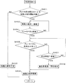
図2ないし図4は、この発明の第2制御例を説明するためのフローチャートであって、図1のフローチャートで示されるルーチンと同様、このフローチャートで示されるルーチンは、所定の短時間毎に繰り返し実行される。この第2制御例として示される制御は、主に、降坂路において制動力保持制御が実行され、その後制動力保持制御が終了されて発進する際の安全性の向上を図るための制御である。 2 to 4 are flowcharts for explaining a second control example of the present invention. Like the routine shown in the flowchart of FIG. 1, the routine shown in this flowchart is repeated every predetermined short time. Executed. The control shown as the second control example is mainly control for improving safety when the braking force holding control is executed on the downhill road, and then the braking force holding control is ended and the vehicle starts.
先ず、図2において、前述の第1制御例の場合と同様に、乗員の意志による制動操作、例えば乗員によるブレーキペダル36の踏み込み操作によって車両Veが停止した状態であるか否かが判断される(ステップS201)。車両Veの停止状態が検出されないことにより、このステップS201で否定的に判断された場合は、以降の制御は実行されずに、このルーチンを一旦終了する。
First, in FIG. 2, as in the case of the first control example described above, it is determined whether or not the vehicle Ve is in a stopped state due to a braking operation by the occupant's will, for example, a depression operation of the
一方、車両Veの停止状態が検出されたことにより、ステップS201で肯定的に判断された場合は、ステップS202へ進み、路面傾斜角が計測され、そのデータが保存される。この路面傾斜角の計測処理については、例えば車両Veに搭載された傾斜角センサ107の検出結果により求めることができる。あるいは、前後加速度センサ106によって得られる路面傾斜角に応じた車両Veの前後方向の加速度の検出結果を基に推定することもできる。また、車輪速センサ101によって得られる各車輪9,10,14,15の回転速度の変化状態から推定することも可能である。またあるいは、ナビゲーションシステム(図示せず)から得られる地理情報などを基に推定することも可能である。
On the other hand, if a positive determination is made in step S201 because the stop state of the vehicle Ve is detected, the process proceeds to step S202, where the road surface inclination angle is measured and the data is stored. The measurement processing of the road surface inclination angle can be obtained from the detection result of the
続いて、ステップS202で求められた路面傾斜角のデータ等を基に、車両Veが下降状態にあるか否かが判断される(ステップS203)。車両Veの下降状態とは、車両Veが坂路においてその降坂方向に前進もしくは後退して下降する状態のことであって、上記の路面傾斜角のデータと、シフトポジションセンサ102および車輪速センサ101および前後加速度センサ106などの検出値とからその状態を判断することができる。車両Veが下降状態であることが検出されないことにより、このステップ203で否定的に判断された場合は、以降の制御は実行されずに、このルーチンを一旦終了する。
Subsequently, it is determined whether or not the vehicle Ve is in a descending state based on the road surface inclination angle data obtained in step S202 (step S203). The descending state of the vehicle Ve is a state in which the vehicle Ve moves forward and backward in the downhill direction on the slope and descends. The road surface inclination angle data, the
一方、車両Veが下降状態であることが検出されたことにより、ステップS203で肯定的に判断された場合には、ステップS204へ進み、その場合の路面傾斜角が予め定められた基準値εよりも小さいか否かが判断される。この基準値εとは、路面傾斜角の大きさに応じて、後述する所定制御1もしくは所定制御2を選択し、適当な制動力保持解除制御を実行するための判断閾値である。したがって、路面傾斜角が基準値εよりも小さいことにより、このステップS204で肯定的に判断された場合は、図3のフローチャートで示す所定制御1が実行される。また、路面傾斜角が基準値ε以上であることにより、ステップS204で否定的に判断された場合には、図4のフローチャートで示す所定制御2が実行される。
On the other hand, if it is determined in step S203 that the vehicle Ve is in a descending state, the process proceeds to step S204, where the road surface inclination angle is determined based on a predetermined reference value ε. It is determined whether or not it is smaller. The reference value ε is a determination threshold value for selecting a predetermined control 1 or a
(所定制御1)
この所定制御1は、平坦路もしくは緩やかな降坂路において車両Veが下降状態である際に、制動力保持制御が実行され、その後制動力保持制御を終了して、すなわち制動力の保持を解除して車両Veを発進させる場合の制御であって、図3において、先ず、ブレーキペダル36の追加踏み込み操作による制動力保持制御の開始の可否が判断される(ステップS301)。このステップS301におけるブレーキペダル36の追加踏み込み操作による制動力保持制御の開始の可否判断は、前述の図1のフローチャートで示す第1制御例におけるステップS101ないしS105と同様の制御内容であり、したがって、ブレーキペダル36の追加踏み込み操作による制動力保持制御の開始可能の判断がされないことにより、このステップS301で否定的に判断された場合は、ステップS302へ進み、制動力保持制御の開始が禁止される。そしてその後、このルーチンを一旦終了する。
(Predetermined control 1)
The predetermined control 1 is that when the vehicle Ve is in a descending state on a flat road or a gentle downhill road, the braking force holding control is executed, and then the braking force holding control is ended, that is, the holding of the braking force is released. In FIG. 3, first, it is determined whether or not the braking force holding control can be started by the additional depression operation of the brake pedal 36 (step S301). Whether to start the braking force holding control by the additional depression operation of the
これに対して、ブレーキペダル36の追加踏み込み操作による制動力保持制御の開始可能の判断がされたことにより、ステップS301で肯定的に判断された場合は、ステップS303へ進み、制動力保持制御が開始・継続される。そして、制動力保持制御が開始・継続されると、ブレーキペダル36の解放操作がおこなわれたか否かが判断される(ステップS304)。
On the other hand, if it is determined affirmative in step S301 because it is determined that the braking force holding control can be started by the additional depression operation of the
ブレーキペダル36の解放操作が検出されないことにより、このステップS304で否定的に判断された場合は、ステップS303へ戻り、それ以降の制御が繰り返し実行される。一方、ブレーキペダル36の解放操作が検出されたことにより、ステップS304で肯定的に判断された場合には、ステップS305へ進み、乗員の発進意志があったか否かが判断される。この乗員の発進意志の判断については、例えば、乗員のシフトレバー(図示せず)などの操作により選択される変速機2のシフトポジション位置もしくはギヤ位置、およびアクセルペダル(図示せず)の踏み込み状態などに基づいて、乗員の発進意志の有無について判断することができる。
If the release operation of the
例えば車両Veに搭載されている変速機2が自動変速機である場合は、シフトレバーなどの操作により選択される変速機2のシフトポジション位置が、D(ドライブ)レンジあるいはR(リバース)レンジである状態を、発進のためのシフトポジション位置とすることができ、特に変速機が有段式の自動変速機である場合には、これらのDレンジおよびRレンジに加えて、L(1速)レンジあるいは2nd(2速)レンジなども発進のためのシフトポジション位置とすることができる。また、例えば車両Veに搭載されている変速機2が手動変速機である場合には、例えばクラッチペダルセンサ(図示せず)により所定量以上のクラッチペダル(図示せず)の踏み込み操作が検出され、シフトレバーなどの操作により選択される変速機2のギヤ位置が、ローギヤあるいはリバースギヤなどのギヤ位置にシフトされた状態を、発進のためのギヤ位置とすることができる。
For example, when the
さらに、アクセルペダルの踏み込み状態の判断は、例えばアクセルペダルセンサ104によって検出されるアクセルペダルの踏み込み量が所定量以上ある場合に乗員の発進意志が有ると判断することができる。なお、アクセルペダルの踏み込み量以外に、例えばアクセルレバーの操作量など、その操作量に応じてエンジン1のスロットル開度を増減させる所定の装置における操作量に基づいて、乗員の発進意志の有無を判断することができる。
Further, the determination of the depressed state of the accelerator pedal can be determined, for example, that the occupant has a willingness to start when the depressed amount of the accelerator pedal detected by the
したがって、例えば、変速機2のシフトポジション位置もしくはギヤ位置が発進のためのシフトポジション位置もしくはギヤ位置に設定されたこと、かつ、アクセルペダルが所定量以上踏み込まれたことにより、このステップS305で肯定的に判断された場合は、ステップS306へ進み、発進のための、例えばアクセルペダルの踏み込み操作が継続され、その後ステップS110へ進み、制動力保持制御が終了される。そしてその後、このルーチンを一旦終了する。
Therefore, for example, when the shift position position or gear position of the
一方、例えば、変速機2のシフトポジション位置もしくはギヤ位置が発進のためのシフトポジション位置もしくはギヤ位置でないこと、あるいは、アクセルペダルが所定量以上踏み込まれていないことなどにより、ステップS305で否定的に判断された場合には、未だ乗員に発進の意志がないものと判断して、ステップS308へ進み、ブレーキペダル36の解放操作が検出された時点から所定時間Tが経過したか否かが判断される。
On the other hand, for example, if the shift position position or gear position of the
ブレーキペダル36の解放操作が検出された時点から所定時間Tが経過したことにより、このステップS308で肯定的に判断された場合は、ステップS309へ進み、制動力保持制御を終了させることを乗員に認識させるための警告音が発信され、あるいは警告が表示され、あるいは警告音の発信と警告の表示との両方がおこなわれ、その後、前述のステップS307へ進み、制動力保持制御が終了される。
If the predetermined time T has elapsed since the time when the release operation of the
これに対して、ブレーキペダル36の解放操作が検出された時点から未だ所定時間Tが経過していないことにより、ステップS308で否定的に判断された場合には、ステップS305へ戻り、それ以降の制御が繰り返し実行される。すなわち、制動力保持制御の実行中に、制動力保持制御の終了条件となる乗員の発進意志が検出されない場合には、ブレーキペダル36が解放された時点から所定時間Tが経過するのを待って、警告音あるいは警告表示などによって乗員に制動力保持制御の終了を予め認識させた上で、自動的に制動力保持制御が終了される。
On the other hand, if the predetermined time T has not yet elapsed from the time when the release operation of the
そのため、乗員による制動操作がおこなわれていない状態での制動力保持制御が、所定時間T以上の長時間に及んで継続されることが回避され、制動装置のブレーキアクチュエータ19などを保護することができる。
Therefore, it is possible to prevent the braking force holding control from being continued for a long period of time equal to or longer than the predetermined time T in a state where the braking operation by the occupant is not performed, and to protect the
(所定制御2)
前述の所定制御1が、平坦路もしくは緩やかな降坂路において車両Veが下降状態である際に、乗員の発進意志が検出された場合に制動力の保持を解除して車両Veを発進させる制御であるのに対して、この所定制御2は、急な降坂路において車両Veが下降状態である際に、乗員によるブレーキペダル36の再踏み込み操作が検出された場合に制動力の保持を解除して車両Veを発進させる制御である。
(Predetermined control 2)
The above-described predetermined control 1 is a control for releasing the holding of the braking force and starting the vehicle Ve when the vehicle Ve is in a descending state on a flat road or a gentle downhill road when the start intention of the occupant is detected. On the other hand, the
図4において、ステップS401ないしS404での制御は、前述の図3に示す所定制御1におけるステップS301ないしS304での制御と同じ制御内容であるため、その説明を省略する。 In FIG. 4, the control in steps S401 to S404 is the same as the control in steps S301 to S304 in the predetermined control 1 shown in FIG.
ステップS404でブレーキペダル36の解放操作が検出されると、ステップS405へ進み、ブレーキペダル36の再踏み込み操作がおこなわれたか否かが判断される。ブレーキペダル36の再踏み込み操作が検出されたことにより、このステップS405で肯定的に判断された場合は、ステップS406へ進み、制動力保持制御が終了されて、車両Veの制動力の保持状態が解除される。そしてその後、このルーチンを一旦終了する。
When the release operation of the
このように、急な降坂路において制動力保持制御が実行される際に、車両Veが坂路においてその降坂方向に前進もしくは後退して下降する下降状態である場合には、乗員によるブレーキペダル36の再踏み込み操作が検出された場合に制動力の保持が解除される。そのため、例えば、急な降坂路においてアクセルペダルの踏み込み操作がおこなわれるのと同時に制動力の保持が解除されることによって、降坂路で車両が急発進したり、乗員の意志以上に車両が下降してしまったりすることを回避することができ、発進時の安全性の向上を図ることができる。
Thus, when the braking force holding control is executed on a steep downhill road, if the vehicle Ve is in a descending state in which the vehicle Ve moves forward or backward in the downhill direction and descends, the
一方、ブレーキペダル36の再踏み込み操作が検出されないことにより、ステップS405で否定的に判断された場合には、ステップS407へ進み、ブレーキペダル36の解放操作が検出された時点から所定時間Tが経過したか否かが判断される。
On the other hand, if a negative depressing operation of the
ブレーキペダル36の解放操作が検出された時点から所定時間Tが経過したことにより、このステップS407で肯定的に判断された場合は、ステップS408へ進み、制動力保持制御を終了させることを乗員に認識させるための警告音が発信され、あるいは警告が表示され、あるいは警告音の発信と警告の表示との両方がおこなわれ、その後、前述のステップS406へ進み、制動力保持制御が終了される。
If the predetermined time T has elapsed since the time when the release operation of the
これに対して、ブレーキペダル36の解放操作が検出された時点から未だ所定時間Tが経過していないことにより、ステップS407で否定的に判断された場合には、ステップS405へ戻り、それ以降の制御が繰り返し実行される。すなわち、制動力保持制御の実行中に、制動力保持制御の終了条件となるブレーキペダル36の再踏み込み操作が検出されない場合には、ブレーキペダル36が解放された時点から所定時間Tが経過するのを待って、警告音あるいは警告表示などによって乗員に制動力保持制御の終了を予め認識させた上で、自動的に制動力保持制御が終了される。
On the other hand, if the predetermined time T has not yet elapsed from the time when the release operation of the
そのため、乗員による制動操作がおこなわれていない状態での制動力保持制御が、所定時間T以上の長時間に及んで継続されることが回避され、制動装置のブレーキアクチュエータ19などを保護することができる。
Therefore, it is possible to prevent the braking force holding control from being continued for a long period of time equal to or longer than the predetermined time T in a state where the braking operation by the occupant is not performed, and to protect the
なお、この発明の制御装置による制御例における制動力保持制御の開始条件、および制動力保持制御の終了条件を、図5および図6のブロック図に示す。図5は、この発明における制動力保持制御の開始条件、すなわちブレーキ液圧保持の開始条件を示している。すなわち、この発明の制御装置では、上記の制御例の中で説明した制動力保持制御の開始条件に加えて、例えばアクセルペダルの踏み込み操作が無いこと、パーキングブレーキが作動していないこと、シフトポジション位置がP(パーキング)レンジ以外であることを含んでおり、それらの各条件が全て成立することにより、制動力保持制御の開始条件が成立するように構成されている。 The starting conditions of the braking force holding control and the ending conditions of the braking force holding control in the control example by the control device of the present invention are shown in the block diagrams of FIGS. FIG. 5 shows the start condition of the braking force holding control in the present invention, that is, the start condition of holding the brake fluid pressure. That is, in the control device of the present invention, in addition to the start condition of the braking force holding control described in the above control example, for example, the accelerator pedal is not depressed, the parking brake is not activated, the shift position It includes that the position is outside the P (parking) range, and the start condition of the braking force holding control is satisfied when all of these conditions are satisfied.
また、図6は、この発明における制動力保持制御の終了条件、すなわちブレーキ液圧保持の解除条件を示している。すなわち、この発明の制御装置では、上記の制御例の中で説明した制動力保持制御の終了条件に加えて、例えばパーキングブレーキが作動していること、シフトポジション位置がP(パーキング)レンジであることを含んでおり、それらの各条件のいずれかが成立することにより、制動力保持制御の終了条件が成立するように構成されている。 FIG. 6 shows a condition for terminating the braking force holding control in the present invention, that is, a condition for releasing the holding of the brake fluid pressure. That is, in the control device of the present invention, in addition to the braking force holding control end condition described in the above control example, for example, the parking brake is operating, and the shift position is in the P (parking) range. In other words, when any one of these conditions is satisfied, the end condition of the braking force holding control is satisfied.
以上のように制御が実行されることによって、例えば乗員によるブレーキペダル36の踏み込み操作などの、乗員の制動操作により車両Veが制動されて停止もしくは車速が所定車速以下になると、その際の乗員の制動操作による、ブレーキペダル36の踏み込み量、あるいはマスタシリンダ圧が検出され、その検出値に基づいて求められる制動操作量が、乗員の第1の制動操作量として検出される。そしてその後、ブレーキペダル36の追加踏み込み操作により、第1の制動操作量に予め定められた適宜の所定量が加えられた値よりも大きい制動操作量が、第2の制動操作量として検出された場合に、車両Veの制動力を保持して車両Veの移動を防止もしくは抑制する制動力保持制御が開始される。そのため、ブレーキペダル36の追加踏み込み操作などの、乗員の意志による簡単な制動操作によって制動力保持制御を開始させることができ、例えば坂路での発進時に車両の下降を防止し、もしくは抑制して発進を補助することができる。
When the control is executed as described above, for example, when the vehicle Ve is braked by the occupant's braking operation such as a depression operation of the
特に、ブレーキペダル36の踏み込み操作による第1の制動操作量の値が予め定められた所定の上限値である上限設定値U以上の場合に、前記所定量の値が小さくされる。すなわち、第1の制動操作量の値が上限設定値Uよりも小さい場合に前記所定量として設定される所定量αに対して、第1の制動操作量の値が上限設定値U以上の場合には、前記所定量として所定量αよりも小さい所定量βが設定される。そのため、最大踏み込み量付近までブレーキペダル36の踏み込み操作がおこなわれた場合に、残りのブレーキペダル36の踏み込み代が少ない場合であっても、ブレーキペダル36の追加踏み込み操作による乗員の第2の制動操作量を適切に検出することができ、乗員の意志による簡単な制動操作によって、より確実に制動力保持制御を開始させることができる。
In particular, the value of the predetermined amount is reduced when the value of the first braking operation amount by the depression operation of the
一方、制動力保持制御が実行されている際、例えばブレーキペダル36の解放操作などの所定の制動装置に対する所定の制動解除操作が、所定時間Tの間継続された場合に、制動力保持制御が終了されて制動力の保持が解除される。そのため、乗員に適切な制動操作もしくは発進操作をおこなうことを促すとともに、ブレーキアクチュエータ19などの制動装置が長時間に及び動作され続けることを回避して装置を保護することができる。
On the other hand, when the braking force holding control is being executed, the braking force holding control is performed when a predetermined braking releasing operation with respect to a predetermined braking device such as a releasing operation of the
また、制動力保持制御の実行中に、車両Veが降坂路において前進もしくは後退して下降する車両Veの下降状態が検出された場合は、ブレーキペダル36が解放され、その後、再びブレーキペダル36の踏み込み操作による前記制動操作量が検出された場合に、制動力保持制御が終了されて制動力の保持が解除される。そのため、例えば急な降坂路において車両Veが停止し、制動力保持制御が実行された際には、ブレーキペダル36の踏み込み操作が再びおこなわれた場合に制動力の保持が解除されるので、急な降坂路での急発進などを回避することができ、発進時の安全性の向上を図ることができる。
In addition, when the descending state of the vehicle Ve in which the vehicle Ve moves forward or backward on the downhill road and is lowered during the execution of the braking force holding control is detected, the
ここで、上述した具体例とこの発明との関係を簡単に説明すると、上述したステップS101の機能的手段が、この発明の車速検出手段に相当し、ステップS102ないしS105の機能的手段が、この発明の制動操作検出手段に相当する。また、ステップS103ないしS106の機能的手段が、この発明の制動力保持手段に相当する。そして、ステップS108ないしS112、およびステップS404ないしS408の機能的手段が、この発明の制動力保持解除手段に相当し、ステップS201ないしS203の機能的手段が、この発明の下降状態検出手段に相当する。 Here, the relationship between the above-described specific example and the present invention will be briefly described. The above-described functional means of step S101 corresponds to the vehicle speed detecting means of the present invention, and the functional means of steps S102 to S105 are this. This corresponds to the braking operation detection means of the invention. The functional means in steps S103 to S106 correspond to the braking force holding means of the present invention. The functional means of steps S108 to S112 and steps S404 to S408 correspond to the braking force holding release means of the present invention, and the functional means of steps S201 to S203 correspond to the descending state detection means of the present invention. .
なお、この発明は、上記の具体例に限定されないのであって、上記の具体例では、この発明を適用した車両が四輪駆動車両である例を示しているが、二輪駆動車両であってもよい。 The present invention is not limited to the above specific example. In the above specific example, the vehicle to which the present invention is applied is a four-wheel drive vehicle. However, the present invention may be a two-wheel drive vehicle. Good.
また、上記の具体例では、車輪に付与する制動力を制御するためのブレーキアクチュエータは、図8に示すように、作動液の液圧によりホールシリンダを動作させるアクチュエータとして例示しているが、例えば電動式のサーボモータにより車輪に制動力を付与するように動作するアクチュエータであってもよく、要は、ブレーキペダルの踏み込み操作などの乗員の制動操作とは別に、車輪に付与する制動力を制御する機構であればよい。 In the above specific example, the brake actuator for controlling the braking force applied to the wheel is illustrated as an actuator that operates the hole cylinder by the hydraulic pressure of the hydraulic fluid as shown in FIG. An actuator that operates to apply braking force to the wheel by an electric servo motor may be used. In short, the braking force applied to the wheel is controlled separately from the occupant's braking operation such as depressing the brake pedal. Any mechanism can be used.
そして、図9に示すように、路面傾斜角を検出するためのセンサとして傾斜角センサが設けられている例を示しているが、傾斜角センサを設けずに、前後加速度センサあるいは車輪速センサなどの検出値を基に路面勾配を推定することも可能である。 As shown in FIG. 9, an example in which an inclination angle sensor is provided as a sensor for detecting a road surface inclination angle is shown. However, without providing an inclination angle sensor, a longitudinal acceleration sensor, a wheel speed sensor, etc. It is also possible to estimate the road gradient based on the detected value.
1…動力源(エンジン)、 2…変速機、 9,10,14,15…車輪、 16…制動装置、 17…ホイールシリンダ、 18…マスタシリンダ、 19…ブレーキアクチュエータ、 36…ブレーキペダル、 100…電子制御装置、 101…車輪速センサ、 102…シフトポジションセンサ、 103…ブレーキペダルセンサ、 106…前後加速度センサ、 107…傾斜角センサ、 108…マスタシリンダ圧センサ、 Ve…車両。
DESCRIPTION OF SYMBOLS 1 ... Power source (engine), 2 ... Transmission, 9, 10, 14, 15 ... Wheel, 16 ... Braking device, 17 ... Wheel cylinder, 18 ... Master cylinder, 19 ... Brake actuator, 36 ... Brake pedal, 100 ...
Claims (4)
前記車両の車速を検出する車速検出手段と、
前記所定の制動装置における前記乗員の制動操作量を検出する制動操作検出手段と、
前記車速検出手段により前記車速が所定車速以下になったことが検出された場合に、前記制動操作検出手段により前記所定の制動装置における前記乗員の第1の制動操作量が検出され、その後、その第1の制動操作量に予め定められた所定量を加えた値よりも大きい前記所定の制動装置における前記乗員の第2の制動操作量が検出された場合に、前記制動力を保持する制動力保持手段と、
前記第1の制動操作量の値が予め定められた所定の上限値以上の場合に、前記所定量の値を小さくする追加制動操作量変更手段と
を備えていることを特徴とする車両の制動制御装置。 In a vehicle braking control device for controlling braking force applied to a wheel by a predetermined braking device that operates based on a braking operation of an occupant,
Vehicle speed detecting means for detecting the vehicle speed of the vehicle;
Braking operation detecting means for detecting a braking operation amount of the occupant in the predetermined braking device;
When it is detected by the vehicle speed detection means that the vehicle speed is equal to or lower than a predetermined vehicle speed, the braking operation detection means detects the first braking operation amount of the occupant in the predetermined braking device, and then when the second brake operation amount of the occupant in the predetermined prescribed amount is large the predetermined braking device than the value obtained by adding the first amount of braking operation is detected, control for holding the braking force Power holding means ;
An additional braking operation amount changing means for reducing the value of the predetermined amount when the value of the first braking operation amount is equal to or greater than a predetermined upper limit value;
Brake control apparatus for a vehicle, characterized in that it comprises.
前記制動力保持解除手段は、前記制動力保持手段により前記制動力の保持がおこなわれた際に、前記下降状態検出手段により前記車両が下降状態であることが検出され、かつ前記制動操作検出手段により前記制動操作量が検出されなくなった後に再び前記制動操作量が検出された場合に、前記制動力の保持を解除する手段を含むことを特徴とする請求項2に記載の車両の制動制御装置。 Further comprising a lowered position detecting means for detecting that before Symbol vehicle is lowered state at downhill,
When the braking force holding means holds the braking force, the braking force holding releasing means detects that the vehicle is in the lowered state by the lowered state detecting means, and the braking operation detecting means wherein when the braking operation quantity again after the braking operation amount is no longer detected is detected, braking control of a vehicle according to claim 2, characterized in that it comprises means you release the holding of the braking force by apparatus.
前記制動操作量は、前記所定の制動装置のマスタシリンダ圧に基づいて決まる物理量であることを特徴とする請求項1ないし3のいずれかに記載の車両の制動制御装置。 The predetermined braking device includes a master cylinder that generates a pressure according to a braking operation of the occupant, and a wheel cylinder that distributes the pressure and applies a braking force to the wheel.
4. The vehicle braking control device according to claim 1, wherein the braking operation amount is a physical amount determined based on a master cylinder pressure of the predetermined braking device.
Priority Applications (1)
| Application Number | Priority Date | Filing Date | Title |
|---|---|---|---|
| JP2005030820A JP4604748B2 (en) | 2005-02-07 | 2005-02-07 | Brake control device for vehicle |
Applications Claiming Priority (1)
| Application Number | Priority Date | Filing Date | Title |
|---|---|---|---|
| JP2005030820A JP4604748B2 (en) | 2005-02-07 | 2005-02-07 | Brake control device for vehicle |
Publications (3)
| Publication Number | Publication Date |
|---|---|
| JP2006213287A JP2006213287A (en) | 2006-08-17 |
| JP2006213287A5 JP2006213287A5 (en) | 2008-03-06 |
| JP4604748B2 true JP4604748B2 (en) | 2011-01-05 |
Family
ID=36976849
Family Applications (1)
| Application Number | Title | Priority Date | Filing Date |
|---|---|---|---|
| JP2005030820A Expired - Fee Related JP4604748B2 (en) | 2005-02-07 | 2005-02-07 | Brake control device for vehicle |
Country Status (1)
| Country | Link |
|---|---|
| JP (1) | JP4604748B2 (en) |
Families Citing this family (9)
| Publication number | Priority date | Publication date | Assignee | Title |
|---|---|---|---|---|
| JP5176569B2 (en) * | 2008-02-01 | 2013-04-03 | トヨタ自動車株式会社 | Brake control device for vehicle |
| CN101983149A (en) | 2008-03-04 | 2011-03-02 | 丰田自动车株式会社 | Brake device |
| JP5036622B2 (en) * | 2008-04-25 | 2012-09-26 | トヨタ自動車株式会社 | VEHICLE CONTROL DEVICE AND VEHICLE |
| JP4952648B2 (en) * | 2008-05-08 | 2012-06-13 | トヨタ自動車株式会社 | VEHICLE CONTROL DEVICE AND VEHICLE |
| WO2011007382A1 (en) * | 2009-07-13 | 2011-01-20 | トヨタ自動車株式会社 | Control device for braking system, and braking system |
| US9260091B2 (en) * | 2013-07-16 | 2016-02-16 | Ford Global Technologies, Llc | Method and system for reducing vacuum consumption in a vehicle |
| JP6027599B2 (en) * | 2014-11-28 | 2016-11-16 | ダイムラー・アクチェンゲゼルシャフトDaimler AG | Vehicle slope start assist device |
| JP2017149215A (en) * | 2016-02-23 | 2017-08-31 | マツダ株式会社 | Vehicular stop holding device |
| JP6699291B2 (en) * | 2016-03-29 | 2020-05-27 | 株式会社アドヴィックス | Brake control device |
Citations (4)
| Publication number | Priority date | Publication date | Assignee | Title |
|---|---|---|---|---|
| JP2000255398A (en) * | 1999-03-03 | 2000-09-19 | Honda Motor Co Ltd | Brake fluid pressure holding device |
| JP2001341624A (en) * | 2000-06-05 | 2001-12-11 | Mitsubishi Electric Corp | Vehicle stop brake device |
| JP2003137080A (en) * | 2001-11-01 | 2003-05-14 | Daihatsu Motor Co Ltd | Holding mechanism of brake hydraulic pressure |
| JP2003327100A (en) * | 2002-05-13 | 2003-11-19 | Honda Motor Co Ltd | Electric parking brake device |
Family Cites Families (7)
| Publication number | Priority date | Publication date | Assignee | Title |
|---|---|---|---|---|
| JPH04215549A (en) * | 1990-12-10 | 1992-08-06 | Mitsubishi Motors Corp | Automatic operation/release system for parking brake |
| JPH0740816A (en) * | 1993-07-29 | 1995-02-10 | Hino Motors Ltd | Slope start auxiliary device |
| JPH08142819A (en) * | 1994-11-22 | 1996-06-04 | Fujitsu Ten Ltd | Brake hold control device |
| JPH08282456A (en) * | 1995-04-10 | 1996-10-29 | Akebono Brake Ind Co Ltd | Auxiliary device for starting at slope |
| DE19611359C1 (en) * | 1996-03-22 | 1997-08-28 | Daimler Benz Ag | Method for preventing a vehicle from accidentally rolling away |
| JPH11321596A (en) * | 1998-05-13 | 1999-11-24 | Mitsubishi Electric Corp | Parking brake device |
| JPH11348744A (en) * | 1998-06-10 | 1999-12-21 | Mitsubishi Electric Corp | Braking device for vehicle |
-
2005
- 2005-02-07 JP JP2005030820A patent/JP4604748B2/en not_active Expired - Fee Related
Patent Citations (4)
| Publication number | Priority date | Publication date | Assignee | Title |
|---|---|---|---|---|
| JP2000255398A (en) * | 1999-03-03 | 2000-09-19 | Honda Motor Co Ltd | Brake fluid pressure holding device |
| JP2001341624A (en) * | 2000-06-05 | 2001-12-11 | Mitsubishi Electric Corp | Vehicle stop brake device |
| JP2003137080A (en) * | 2001-11-01 | 2003-05-14 | Daihatsu Motor Co Ltd | Holding mechanism of brake hydraulic pressure |
| JP2003327100A (en) * | 2002-05-13 | 2003-11-19 | Honda Motor Co Ltd | Electric parking brake device |
Also Published As
| Publication number | Publication date |
|---|---|
| JP2006213287A (en) | 2006-08-17 |
Similar Documents
| Publication | Publication Date | Title |
|---|---|---|
| JP4604748B2 (en) | Brake control device for vehicle | |
| US7125085B2 (en) | Braking force retaining unit | |
| JP5935886B2 (en) | Vehicle control device | |
| JP6089504B2 (en) | Vehicle control device | |
| US20130024090A1 (en) | Vehicle control apparatus | |
| JP2001354126A (en) | Vehicular brake device | |
| JPWO2011074037A1 (en) | Vehicle control device | |
| CN108204454B (en) | Control device for all-wheel drive vehicle | |
| US7182412B2 (en) | Brake controller | |
| JP4839865B2 (en) | Control device for automatic transmission | |
| JP5336498B2 (en) | Automobile climbing slope start assist device | |
| US6478716B2 (en) | Vehicle deceleration controller | |
| JP2006232094A (en) | Brake control device for vehicle | |
| JP2006315569A (en) | Vehicular braking control device | |
| JP2006327369A (en) | Vehicular braking control device | |
| JP2006306350A (en) | Brake controlling device for vehicle | |
| WO2016136874A1 (en) | Vehicle control device for controlling coasting travel of vehicle | |
| JP4462046B2 (en) | Brake control device for vehicle | |
| JP2007008238A (en) | Vehicle control apparatus | |
| JP7180162B2 (en) | vehicle controller | |
| JP2015034569A (en) | Shift control device for vehicle | |
| JP2005105894A (en) | Automatic engine stop device for vehicle | |
| JP4428239B2 (en) | Brake control device for vehicle | |
| JP2006306351A (en) | Brake controlling device for vehicle | |
| JP3624930B2 (en) | Slope start assist device |
Legal Events
| Date | Code | Title | Description |
|---|---|---|---|
| A521 | Written amendment |
Free format text: JAPANESE INTERMEDIATE CODE: A523 Effective date: 20080123 |
|
| A621 | Written request for application examination |
Free format text: JAPANESE INTERMEDIATE CODE: A621 Effective date: 20080123 |
|
| A977 | Report on retrieval |
Free format text: JAPANESE INTERMEDIATE CODE: A971007 Effective date: 20091127 |
|
| TRDD | Decision of grant or rejection written | ||
| A01 | Written decision to grant a patent or to grant a registration (utility model) |
Free format text: JAPANESE INTERMEDIATE CODE: A01 Effective date: 20100907 |
|
| A01 | Written decision to grant a patent or to grant a registration (utility model) |
Free format text: JAPANESE INTERMEDIATE CODE: A01 |
|
| A61 | First payment of annual fees (during grant procedure) |
Free format text: JAPANESE INTERMEDIATE CODE: A61 Effective date: 20100920 |
|
| FPAY | Renewal fee payment (event date is renewal date of database) |
Free format text: PAYMENT UNTIL: 20131015 Year of fee payment: 3 |
|
| LAPS | Cancellation because of no payment of annual fees |