JP4604635B2 - Hot water supply device equipped with a drain treatment device - Google Patents
Hot water supply device equipped with a drain treatment device Download PDFInfo
- Publication number
- JP4604635B2 JP4604635B2 JP2004291859A JP2004291859A JP4604635B2 JP 4604635 B2 JP4604635 B2 JP 4604635B2 JP 2004291859 A JP2004291859 A JP 2004291859A JP 2004291859 A JP2004291859 A JP 2004291859A JP 4604635 B2 JP4604635 B2 JP 4604635B2
- Authority
- JP
- Japan
- Prior art keywords
- drain
- oil
- fuel oil
- combustion gas
- tank
- Prior art date
- Legal status (The legal status is an assumption and is not a legal conclusion. Google has not performed a legal analysis and makes no representation as to the accuracy of the status listed.)
- Expired - Fee Related
Links
Images

Landscapes
- Physical Water Treatments (AREA)
- Water Treatment By Sorption (AREA)
- Instantaneous Water Boilers, Portable Hot-Water Supply Apparatuses, And Control Of Portable Hot-Water Supply Apparatuses (AREA)
- Details Of Fluid Heaters (AREA)
Description
本発明は、燃焼ガスの温度が露点以下となることにより発生するドレイン(凝縮水)を適切に処理するためのドレイン処理装置を備えた給湯装置に関する。 The present invention relates to a hot water supply apparatus including a drain treatment device for appropriately treating a drain (condensed water) generated when the temperature of a combustion gas becomes a dew point or lower.
給湯装置としては、いわゆる潜熱回収型の熱交換器を備えたものがある。このタイプの給湯装置においては、灯油や都市ガスなどを燃焼器によって燃焼させて得られた燃焼ガスの顕熱が熱交換器によって回収されるだけではなく、燃焼ガスの潜熱も回収される。したがって、熱交換効率を高くすることができる。前記した潜熱回収がなされると、燃焼ガス中の水蒸気が凝縮し、多量のドレインが発生するが、このドレインは、燃焼ガス中の硫黄酸化物や窒素酸化物などを吸収したPH3程度の強酸性となる。ドレインを強酸性のまま一般配管中に排水させたのでは、一般配管に腐食などを生じさせる他、水質汚染などの環境悪化を招く。 Some hot water supply apparatuses include a so-called latent heat recovery type heat exchanger. In this type of hot water supply apparatus, not only the sensible heat of combustion gas obtained by burning kerosene or city gas with a combustor is recovered by a heat exchanger, but also latent heat of the combustion gas is recovered. Therefore, the heat exchange efficiency can be increased. When the latent heat recovery described above is performed, water vapor in the combustion gas is condensed and a large amount of drain is generated. This drain is a strong acid of about PH3 that absorbs sulfur oxide, nitrogen oxide, etc. in the combustion gas. It becomes. If the drain is drained into the general piping with strong acidity, the general piping will be corroded and the environment will be deteriorated such as water pollution.
そこで、従来においては、たとえば特許文献1,2に記載されているように、中和剤を収容した中和器を給湯装置に組み付けて、給湯装置の内部において発生したドレインを前記中和器内に流入させる手段が用いられている。このような手段によれば、ドレインが中和剤によって中和され、強酸性のまま廃棄されないようにすることができる。 Therefore, conventionally, as described in Patent Documents 1 and 2, for example, a neutralizer containing a neutralizing agent is assembled to a hot water supply device, and a drain generated inside the hot water supply device is disposed in the neutralizer. Means for inflowing into is used. According to such means, the drain can be neutralized by the neutralizing agent, and can be prevented from being discarded while remaining strongly acidic.
しかしながら、前記従来技術においては、次に述べるように、未だ改善すべき余地があった。 However, the prior art still has room for improvement as described below.
すなわち、燃焼器として、たとえば灯油などの燃料オイルを噴霧ノズルから噴霧させて燃焼させる型式のものを用いた場合、着火時、消火時、あるいはそれ以外の不完全燃焼時において、噴霧ノズルから噴霧されている燃料オイルが、未燃のままドレインに混入する場合がある。また、給湯装置を比較的長期間にわたって使用した場合には、たとえば給湯装置の内部に煤が付着したり、あるいは錆が発生し、これらが脱落してドレインに混入するような場合もある。ところが、前記従来技術においては、中和剤を収容した中和器を用いてドレインの中和処理を行なうに過ぎない。このため、従来技術においては、ドレインに燃料オイルなどが混入している場合であっても、これらの排除がなされることなく、ドレインが廃棄されている。これでは、水質汚染を生じ、環境保護の観点から好ましくない。 That is, when a combustor of the type in which fuel oil such as kerosene is sprayed from a spray nozzle and combusted is used, it is sprayed from the spray nozzle at the time of ignition, extinguishing, or other incomplete combustion. In some cases, the remaining fuel oil enters the drain unburned. Further, when the hot water supply device is used for a relatively long period of time, for example, soot may adhere to the inside of the hot water supply device, or rust may be generated, and these may drop off and enter the drain. However, in the prior art, the neutralization of the drain is only performed using a neutralizer containing a neutralizing agent. For this reason, in the prior art, even if fuel oil or the like is mixed in the drain, the drain is discarded without being eliminated. This causes water pollution and is not preferable from the viewpoint of environmental protection.
なお、本出願人は、従来において、特許文献3に記載されているドレイン中和器を提案している。この従来のドレイン中和器は、中和処理槽の前段にダストポットが設けられており、このダストポット内においてドレインに含まれている夾雑物が沈殿するようになっている。そして、前記ダストポット内のドレインのうち、上層領域の夾雑物を含まないドレインのみが中和処理槽に流入するようになっている。このような構成によれば、ダストポット内に沈殿する夾雑物については排除可能であるものの、燃料オイルがドレインに混入している場合には、ドレイン上に燃料オイルが浮いてしまうため、この燃料オイルを排除することはできない。
Note that the present applicant has conventionally proposed a drain neutralizer described in
本発明は、このような事情のもとで考え出されたものであって、ドレインに未燃の燃料オイルが混入している場合であっても、このドレインの廃棄に起因して水質汚染などが生じる虞れを適切に解消することが可能なドレイン処理装置を備えた給湯装置を提供することを、その課題としている。 The present invention has been conceived under such circumstances, and even when unburned fuel oil is mixed in the drain, water pollution and the like are caused by the disposal of the drain. It is an object of the present invention to provide a hot water supply device including a drain processing device that can appropriately eliminate the possibility of occurrence of water.
上記の課題を解決するため、本発明では、次の技術的手段を講じている。 In order to solve the above problems, the present invention takes the following technical means.
本発明により提供されるドレイン処理装置を備えた給湯装置は、燃料オイルを下向きに燃焼させる燃焼器と、この燃焼器によって発生された燃焼ガスを下向きに進行させてから略U字状に屈曲または湾曲した底部を介して上向きに進行させて排気口まで流通させる燃焼ガス流路と、前記燃焼器の下方領域において前記燃焼ガスとの熱交換を行なう通水用の管体を有する熱交換器と、前記熱交換によって発生するドレインを中和するための中和処理槽を有するドレイン処理装置と、を備えている、給湯装置であって、前記燃焼ガス流路の底部には、前記熱交換器から落下するドレインを受けて一定の箇所に集めることが可能な傾斜面を有する底板部と、この底板部によって一定の箇所に集められたドレインを前記燃焼ガス流路の外部に排出させる排出口とが設けられているとともに、前記底板部の下方には、空間スペースが形成されており、前記ドレイン処理装置は、少なくともその一部分が前記空間スペース内に位置して、前記排出口から排出されるドレインを受けるように設けられ、かつ前記ドレインに燃料オイルが混入しているときに、前記ドレインが前記中和処理槽に流入する前または後の段階において、前記燃料オイルを捕捉可能なオイル捕捉手段を備えていることを特徴としている。 A hot water supply apparatus provided with a drain treatment apparatus provided by the present invention comprises a combustor that burns fuel oil downward, and a combustion gas generated by the combustor is advanced downward and then bent or bent into a substantially U shape. A combustion gas flow path that flows upward through a curved bottom and flows to the exhaust port; and a heat exchanger that has a water passage tube that performs heat exchange with the combustion gas in a lower region of the combustor. And a drain treatment device having a neutralization treatment tank for neutralizing the drain generated by the heat exchange, wherein the heat exchanger is provided at the bottom of the combustion gas flow path. The bottom plate portion having an inclined surface that can be collected at a certain location by receiving the drain falling from the drain, and the drain collected at the certain location by the bottom plate portion is discharged to the outside of the combustion gas flow path. And a drain space is formed below the bottom plate portion, and the drain processing device is at least partially located in the space space and is discharged from the drain port. provided to receive a drain that is, and when the fuel oil is mixed with the drain, at the stage of before or after the drain flows into the neutralization tank, capable of capturing the oil the fuel oil It is characterized by having a capturing means.
本発明によれば、燃料オイルを燃焼させる際の着火不良やその他の事由に起因して、ドレインに不燃の燃料オイルが混入しても、この燃料オイルはオイル捕捉手段によって捕捉
される。もちろん、中和処理槽によってドレインの中和処理も適切に行なわれる。したがって、燃料オイルを含まず、かつ適切に中和処理されたドレインをドレイン処理装置の外部に排出することが可能となり、水質汚染の防止、環境保護を図るのに好適となる。さらに、前記構成によれば、燃料オイルを下向きに燃焼させるいわゆる逆燃方式とされており、燃焼ガスが燃焼器の下方に進行すると熱交換器の作用によってドレインが発生するが、このドレインは、燃焼ガス流路の底部の底板部によって的確に、かつ迅速に集められて前記底板部の下方に配されているドレイン処理装置に送り込まれる。したがって、燃焼ガス流路内において発生したドレインをドレイン処理装置に送り込む構造が簡素となり、またドレインが流れる距離も短くして、燃焼ガス流路内に多くのドレインが残存しないようにすることができる。また、ドレイン処理装置の少なくとも一部分は、前記底板部の下方に位置するため、ドレイン処理装置をスペース効率良く給湯装置に組み込むこともできる。
According to the present invention, even if non-combustible fuel oil is mixed into the drain due to poor ignition when the fuel oil is burned or other reasons, the fuel oil is captured by the oil capturing means. Of course, the neutralization treatment of the drain is also appropriately performed by the neutralization treatment tank. Therefore, the drain which does not contain fuel oil and is appropriately neutralized can be discharged to the outside of the drain treatment apparatus, which is suitable for preventing water pollution and protecting the environment. Furthermore, according to the above-described configuration, a so-called reverse combustion method in which fuel oil is burned downward is generated, and when the combustion gas travels below the combustor, a drain is generated by the action of the heat exchanger. The fuel is collected accurately and quickly by the bottom plate at the bottom of the combustion gas flow path and sent to the drain processing apparatus disposed below the bottom plate. Therefore, the structure for sending the drain generated in the combustion gas flow path to the drain processing apparatus is simplified, and the distance through which the drain flows can be shortened so that many drains do not remain in the combustion gas flow path. . Further, since at least a part of the drain processing apparatus is located below the bottom plate portion, the drain processing apparatus can be incorporated into the hot water supply apparatus with high space efficiency.
本発明の好ましい実施の形態において、前記ドレイン処理装置は、前記ドレインを所定の液面高さに貯留可能な分離処理槽を備えており、この分離処理槽には、この分離処理槽内をドレインの流入部および流出部をそれぞれ有する第1および第2のチャンバに仕切るとともに、これら第1および第2のチャンバの下部どうしまたは高さ方向中間部どうしを連通部を介して連通させる仕切壁が設けられており、前記仕切壁は、前記第1のチャンバ内においてドレイン上に浮く燃料オイルが前記第2のチャンバに流入することを抑制することにより前記燃料オイルを捕捉可能であり、前記分離処理槽が前記オイル捕捉手段を構成している。このような構成によれば、燃料オイルをドレインとの比重差を利用して、分離処理槽の第1のチャンバ内に捕捉することが可能であり、簡易な構造の分離処理槽を利用して燃料オイルの適切な捕捉処理が実現される。また、前記第1のチャンバ内においては、燃料オイル以外として、ドレインとは比重が相違する固形状などの夾雑物をドレイン上に浮かせ、あるいは沈殿させることによって分離捕捉することも可能となる。 In a preferred embodiment of the present invention, the drain treatment apparatus includes a separation treatment tank capable of storing the drain at a predetermined liquid level, and the separation treatment tank includes a drain in the separation treatment tank. A partition wall is provided for partitioning the first and second chambers having inflow and outflow portions of the first and second chambers, and for communicating the lower portions of the first and second chambers or the intermediate portions in the height direction through the communication portions. The partition wall is capable of capturing the fuel oil by suppressing the fuel oil floating on the drain in the first chamber from flowing into the second chamber, and the separation processing tank Constitutes the oil catching means. According to such a configuration, it is possible to capture the fuel oil in the first chamber of the separation processing tank using the specific gravity difference with the drain, and the separation processing tank having a simple structure is used. Appropriate capture processing of the fuel oil is realized. Further, in the first chamber, it is possible to separate and capture a solid matter or the like having a specific gravity different from that of the drain other than fuel oil by floating or precipitating on the drain.
本発明の好ましい実施の形態においては、前記分離処理槽内には、オイル吸着フィルタが配されている。このような構成によれば、仮に、分離処理槽の第1のチャンバにおいて燃料オイルの全量を捕捉することができなくても、この燃料オイルをオイル吸着フィルタによって捕捉することができる。したがって、分離処理槽の下流に燃料オイルが不当に流れることを適切に防止または抑制することが可能となる。 In a preferred embodiment of the present invention, an oil adsorption filter is disposed in the separation processing tank. According to such a configuration, even if the entire amount of fuel oil cannot be captured in the first chamber of the separation processing tank, the fuel oil can be captured by the oil adsorption filter. Therefore, it is possible to appropriately prevent or suppress the fuel oil from flowing inappropriately downstream of the separation processing tank.
本発明の好ましい実施の形態においては、前記分離処理槽内に貯留されたドレインの液面が所定のレベル以上に上昇したときにこれを検知可能な検知手段を備えている。このような構成によれば、なんらかの事情により、分離処理槽の後段またはそれよりも下流側において、詰まりなどを生じ、分離処理槽内のドレインの液面レベルが上昇すると、その旨が検出手段によって検出される。したがって、この検出に基づき、ユーザは前記詰まりを解消するなどの適切な対応措置を採ることができる。 In a preferred embodiment of the present invention, there is provided detection means capable of detecting when the liquid level of the drain stored in the separation processing tank rises above a predetermined level. According to such a configuration, for some reason, clogging or the like occurs at the rear stage of the separation processing tank or downstream thereof, and when the liquid level of the drain in the separation processing tank rises, this is detected by the detection means. Detected. Therefore, based on this detection, the user can take an appropriate countermeasure such as eliminating the clogging.
本発明の好ましい実施の形態においては、前記分離処理槽内に貯留されたドレインを外部に排出させるための開閉自在な排出口を備えている。このような構成によれば、前記分離処理槽を長期間にわたって不使用とするような場合には、その内部からドレインを抜いておくことにより、凍結防止などを適切に図ることができる。また、分離処理槽の底部に多くの夾雑物が沈殿しているような場合には、ドレインとともにこの夾雑物を外部に排出させることも可能となる。 In a preferred embodiment of the present invention, an openable / closable discharge port is provided for discharging the drain stored in the separation treatment tank to the outside. According to such a configuration, when the separation tank is not used for a long period of time, it is possible to appropriately prevent freezing by removing the drain from the inside. In addition, when a large amount of foreign matter is precipitated at the bottom of the separation treatment tank, it is possible to discharge this foreign matter together with the drain.
本発明の好ましい実施の形態においては、前記中和処理槽は、ドレインを所定の液面高さに貯留可能であるとともに、この中和処理槽には、この中和処理槽内をドレインの流入部および流出部をそれぞれ有する第1および第2のチャンバに仕切るとともに、これら第1および第2のチャンバの下部どうしまたは高さ方向中間部どうしを連通部を介して連通させる仕切壁が設けられており、前記仕切壁は、前記第1のチャンバ内においてドレイン上に浮く燃料オイルが前記第2のチャンバに流入することを抑制して前記燃料オイルを捕捉可能であり、前記中和処理槽の前記仕切壁を備えた部分は、前記オイル捕捉手段を構成している。このような構成によれば、前記した分離処理槽と同様な原理により、前記中和処理槽の内部においても、燃料オイルをドレインとの比重差を利用してこの中和処理槽の第1のチャンバ内において浮かせて捕捉することができる。したがって、燃料オイルの捕捉がより確実化される。また、中和処理槽自体にオイル捕捉機能を具備させているために、スペース効率などの観点からしても好ましいものとなる。 In a preferred embodiment of the present invention, the neutralization treatment tank can store the drain at a predetermined liquid level, and the neutralization treatment tank has an inflow of drain through the neutralization treatment tank. A partition wall is provided for partitioning the first and second chambers having a portion and an outflow portion, and for communicating the lower portions or the height direction intermediate portions of the first and second chambers via the communicating portion. And the partition wall is capable of capturing the fuel oil by suppressing the fuel oil floating on the drain in the first chamber from flowing into the second chamber, and the partition wall of the neutralization tank The part provided with the partition wall constitutes the oil capturing means. According to such a configuration, on the basis of the same principle as that of the separation treatment tank described above, also in the neutralization treatment tank, the first difference of the neutralization treatment tank is obtained using the difference in specific gravity between the fuel oil and the drain. It can be floated and captured in the chamber. Therefore, the capture of the fuel oil is further ensured. Moreover, since the neutralization tank itself has an oil trapping function, it is preferable from the viewpoint of space efficiency.
本発明の好ましい実施の形態においては、前記中和処理槽内には、この中和処理槽の底部から起立してこの中和処理槽内の底部近傍領域を複数の領域に区分する少なくとも1つの起立壁が設けられており、前記複数の領域の1つに流入したドレインは、前記起立壁を越えることによって他の隣の領域に流入するように構成されている。このような構成によれば、前記起立壁の存在により、中和処理槽内をドレインが流通する際の流路長が長くなる。したがって、中和処理槽の全体サイズを小さくしつつ、ドレインの中和処理を適切に行なうことが可能となる。 In a preferred embodiment of the present invention, in the neutralization treatment tank, at least one that stands from the bottom of the neutralization treatment tank and divides a region near the bottom in the neutralization treatment tank into a plurality of regions. A standing wall is provided, and the drain that has flowed into one of the plurality of regions is configured to flow into another adjacent region by crossing the standing wall. According to such a configuration, due to the presence of the standing wall, the flow path length when the drain flows through the neutralization treatment tank becomes long. Therefore, the neutralization treatment of the drain can be appropriately performed while reducing the overall size of the neutralization treatment tank.
本発明の好ましい実施の形態においては、前記オイル捕捉手段よりも前記ドレインの下流位置において、前記ドレインに残存混入しているオイルを検出可能なオイルセンサをさらに備えている。既述したとおり、本発明によれば、通常時においては、ドレインに混入したオイルはオイル捕捉手段によって捕捉され、このオイル捕捉手段よりも下流にオイルが流れることは抑制されている。ところが、なんらかのトラブルが発生するなどして、前記オイル捕捉手段によってドレインに混入しているオイルを適切に捕捉できない異常事態の発生があり得る。前記構成によれば、そのような異常事態が発生した場合には、これを的確に察知することが可能となり、対応策を迅速に採ることが可能となる。前記トラブルの一例としては、たとえば燃焼器において燃料オイル漏れが生じ、ドレイン処理装置のオイル捕捉手段によってはオイル捕捉が困難なほど、多くの燃料オイルがドレインに混入するといった事態が挙げられる。 In a preferred embodiment of the present invention, an oil sensor further capable of detecting oil remaining in the drain is further provided at a position downstream of the drain than the oil trapping means. As described above, according to the present invention, in a normal time, the oil mixed in the drain is captured by the oil capturing means, and the oil is prevented from flowing downstream from the oil capturing means. However, there may be an abnormal situation in which some trouble occurs and the oil trapping means cannot properly capture the oil mixed in the drain. According to the above-described configuration, when such an abnormal situation occurs, it is possible to accurately detect this and it is possible to take a countermeasure quickly. As an example of the trouble, for example, there is a situation in which fuel oil leaks in a combustor and so much fuel oil is mixed into the drain that oil capture is difficult by the oil trapping means of the drain treatment device.
本発明の好ましい実施の形態においては、前記ドレイン処理装置は、前記空間スペースへの装着脱が自在な容器を備えており、かつこの容器内に前記中和剤が収容されていることにより前記中和処理槽が形成されているとともに、前記容器内に前記オイル捕捉手段が収容された構成とされている。このような構成によれば、前記容器を前記空間スペースに装着脱させることによって、中和処理槽とオイル捕捉手段との双方の装着脱がなされることとなり、ドレイン処理装置がいわゆるカートリッジ方式となる。このことにより、ドレイン処理装置を給湯装置の所定位置に取り付けたり、あるいは取り外したりする作業が容易となる。とくに、中和剤やオイル捕捉手段を一括して交換する仕様とする場合に、最適である。 In a preferred embodiment of the present invention, the drain treatment apparatus includes a container that can be freely attached to and detached from the space, and the neutralizing agent is accommodated in the container so that the neutralization is performed. A treatment tank is formed, and the oil capturing means is housed in the container. According to such a configuration, by attaching / detaching the container to / from the space space, both the neutralization tank and the oil catching means are attached / detached, and the drain processing apparatus is a so-called cartridge system. This facilitates the work of attaching or removing the drain treatment device at a predetermined position of the hot water supply device. In particular, it is optimal when the neutralizing agent and the oil capturing means are to be replaced at once.
本発明の好ましい実施の形態においては、前記燃焼ガス流路の底部を構成する底部ケーシングを有しているとともに、この底部ケーシングは、前記底板部の下方において前記オイル捕捉手段と中和剤とを収容する収容部を形成していることにより、前記ドレイン処理装置が構成されている。このような構成によれば、前述したカートリッジ方式の場合とは異なり、底部ケーシングとは別体の容器を用いることなくドレイン処理装置を構成することができ、給湯装置全体の製造コストの低減などを図るのに好適となる。 In a preferred embodiment of the present invention, a bottom casing that constitutes a bottom of the combustion gas flow path is provided, and the bottom casing has the oil capturing means and the neutralizing agent below the bottom plate. The drain processing apparatus is configured by forming an accommodating portion for accommodating. According to such a configuration, unlike the case of the cartridge system described above, the drain treatment apparatus can be configured without using a container separate from the bottom casing, and the manufacturing cost of the entire hot water supply apparatus can be reduced. It is suitable for aiming.
本発明のその他の特徴および利点は、添付図面を参照して以下に行なう発明の実施の形態の説明から、より明らかになるであろう。 Other features and advantages of the present invention will become more apparent from the following description of embodiments of the present invention with reference to the accompanying drawings.
以下、本発明の好ましい実施の形態を、図面を参照して具体的に説明する。 Hereinafter, preferred embodiments of the present invention will be described in detail with reference to the drawings.
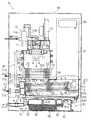
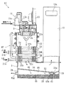
図1は、本発明に係るドレイン処理装置を備えた給湯装置の一実施形態を示している。本実施形態の給湯装置A1は、燃焼器1、熱交換器HT、底部ケーシング3、消音器19、ドレイン処理装置B1、およびこれら全体を覆う外装ケース90を具備している。
Figure 1 shows an embodiment of a water heater having a drain processing equipment according to the present invention. The hot water supply device A1 of the present embodiment includes a combustor 1, a heat exchanger HT, a
燃焼器1は、灯油などのオイルを燃料とし、かつこの燃料を噴霧ノズル10から下向きに噴射させて、点火プラグ12によって着火させて燃焼させる逆燃方式のものであり、熱交換器HTの缶体20上に載設された缶体11内の上部に噴霧ノズル10が設けられた構成を有している。この噴霧ノズル10には、オイルタンク(図示略)から燃料供給部15を介して燃料オイルが供給される。燃料供給部15は、電磁ポンプ、電磁弁15a、およびオイル供給用配管15bなどを有している。缶体11上には、缶体11内に燃焼用空気を下向きに送り込む送風ファン13が設けられており、前記燃焼用空気は、噴霧ノズル10の周囲およびその下方領域にわたって設けられた燃焼筒14内に進入するようになっている。燃焼筒14は、その周壁に複数の通気孔を有しており、この燃焼筒14内において前記燃焼用空気を旋回流として、噴霧されたオイルと燃焼用空気との混合を促進する役割を果たす。
The combustor 1 is of a reverse combustion type that uses oil such as kerosene as fuel, injects the fuel downward from the spray nozzle 10 and ignites and burns it by the spark plug 12, and is a can of the heat exchanger HT. The spray nozzle 10 is provided in the upper part in the
底部ケーシング3は、缶体20および消音器19のそれぞれを支持するようにそれらの下方に配され、かつそれらに接続されている。缶体20内、底部ケーシング3内、および消音器19内は、一連に繋がった燃焼ガス流路であり、燃焼器1で発生された燃焼ガスは、缶体20内を下向きに進行して底部ケーシング3内に流入した後に、上向きに方向転換して消音器19に流入し、この消音器19の上部に設けられた排気口19aから排ガスとして外部に排出される。このように底部ケーシング3を用いることによって燃焼ガス流路を略U字状に屈曲または湾曲させた構成においては、燃焼器1や缶体20の一側方に消音器19を起立させた姿勢でスペース効率良く設けることができ、全体の小型化を図るのに好適となる。
The
熱交換器HTは、通水用の管体22a,22bおよびU字管23内に供給される水と燃焼ガスとの熱交換を行なうためのものであり、燃焼ガスの顕熱を回収するための1次熱交換部2Aと、潜熱を回収するための2次熱交換部2Bとを有している。1次熱交換部2Aは、管体22aが缶体20の周囲に巻回されている部分と、複数のフィン24を備えた管体22bが缶体20を略水平方向に貫通するように設けられた部分とを有している。
The heat exchanger HT is for performing heat exchange between the water supplied into the
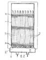
2次熱交換部2Bは、底部ケーシング3内に複数のU字管23が設けられ、かつ底部ケーシング3の外部にはそれらU字管23に通水を行なわせるためのヘッダ部25が設けられた構成を有している。各U字管23の一対の開口部23a,23bを有する基端部は、底部ケーシング3の一側壁30aを貫通し、かつヘッダ部25に接続されて支持されている。これに対し、各U字管23の先端部23cは不支持状態の自由端とされており、各U字管23は、いわゆる片もち支持となっている。この支持構造は、温度変化に起因する膨張および収縮時の応力を減少させるのに好適である。
The secondary
複数のU字管23は、一対の開口部23a,23bが上下方向に並ぶ姿勢とされ、かつ図3に示すように、これら複数のU字管23の長手方向と交差する方向に適当な間隔で並べられている。それら複数のU字管23は、互いに隣り合うものどうしの高さが相違するように段違い状に並べられている。このような配列にすると、燃焼ガスが複数のU字管23に触れる度合いが大きくなり、熱交換の効率が高められる効果が期待できる。ただし、これに限定されず、複数のU字管23の高さを同一に揃えた配列としてもかまわない。また、複数のU字管23には、熱交換の効率を高めるための手段として、複数枚のプレート状のフィン26が設けられている。
The plurality of U-tubes 23 are arranged such that a pair of
図1によく表われているように、各U字管23は、底部ケーシング3の一側壁30aから缶体20の底部開口部の直下領域を越えて消音器19の直下領域まで延びた長寸法とされている。各U字管23の長手方向中間部のフィン26aの上部と底部ケーシング3の上壁部30cとの隙間部分には、この隙間部分を閉塞して、燃焼ガスが通過することを阻止する遮断板31が設けられている。また、底部ケーシング3内のうち、他側壁30b寄りの部分には、この他側壁30bと各U字管23の先端部23cとの隙間33に対してその下方から燃焼ガスが進行することを阻止する遮断板32が設けられている。これら2つの遮断板31,32は、底部ケーシング3内において燃焼ガスを複数のU字管23やフィン26に作用させて熱交換の効率を高めるのに役立つ。
As shown well in FIG. 1, each
ヘッダ部25は、複数のU字管23の開口部23a,23bのそれぞれに連通した一対のチャンバ25a,25bを有している。チャンバ25aには、入水口21aを有する管体が連結され、チャンバ25bには、管体22aの上流端22a'が連結されている。本実施形態の熱交換器HTにおいては、入水口21aに入水された水は、ヘッダ部25のチャンバ25aに流入した後に、複数のU字管23を通過しながら加熱されてチャンバ25bに流出する。次いで、この水は、管体22a,22bを順次流れながら加熱され、その後出湯口21bから流出して所定の給湯先に供給される。各U字管23に対して未加熱状態の低温の水を供給すれば、燃焼ガス中の水蒸気の潜熱回収の効率が高められる。ただし、本発明は、1次熱交換部2Aおよび2次熱交換部2Bに対する通水の仕方はこれに限定されるものではない。
The
2次熱交換部2Bを構成する複数のU字管23およびフィン26には、潜熱回収に起因するドレインが付着する。したがって、好ましくは、これらの部分は耐食性に優れたステンレスなどの材質とされている。また、底部ケーシング3の底板部34など、前記ドレインと接触する虞れのある金属部分も、好ましくは前記と同様な材質とされている。ただし、底部ケーシング3の全体あるいは底板部34などの一部分については、たとえば合成樹脂製とし、その製造コストを廉価にすることが可能である。熱交換器HTは、潜熱回収機能を備えており、燃焼ガスが底部ケーシング3の底部に進行するまでの間に燃焼ガスの温度を十分に低下させることができるからである。1次熱交換部2Aについては、ドレインに関する問題が少なく、管体22bやフィン24は熱伝導や加工性などに優れたたとえば銅または銅合金製である。各U字管23は、先端部23cよりも基端部の方が低い高さとなるように傾斜している。このような構成によれば、給湯装置A1を長期間不使用にするなどの理由から各U字管23内の水抜きを行なう場合に、前記傾斜を利用して、各U字管23内の水を前記基端部側に流れさせ、前記作業をスムーズに行なうことができる。
Drains resulting from latent heat recovery adhere to the plurality of
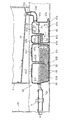
ドレイン処理装置B1は、分離処理槽4A、中和処理槽4B、およびオイルセンサ5が装着されたドレイン流通管50を備えている。分離処理槽4Aおよび中和処理槽4Bは、たとえばブロー成形された合成樹脂製の容器40を利用して一体的に形成されたカートリッジタイプに形成されている。容器40の一端寄り領域(同図の左端寄り領域)が中和処理槽4Bであり、炭酸カルシウムなどの粒状の中和剤48を収容している。容器40の他端寄り領域は、分離処理槽4Aである。容器40の少なくとも一部分は、底部ケーシング3の下方に形成された空間スペース91に配されていることにより、ドレイン処理装置B1の全体は、外装ケース90内の底部にスペース効率良く収容されている。
The drain treatment apparatus B1 includes a
底部ケーシング3の底板部34には、2次熱交換部2Bから滴下してきたドレインを排出するための排出口34aが設けられており、この排出口34aから分離処理槽4Aに適当なパイプ部34bを介してドレインが流入するように構成されている。底板部34は、2次熱交換部2Bから滴下してきたドレインを排出口34aに集めることができるように、排出口34aに接近するほど高さが低くなる傾斜面とされている。図面には表われていないが、底板部34は、図1の紙面と直交する方向においてもドレインを排出口34aに集めるように傾斜している。
The
分離処理槽4Aは、次に述べるように、ドレインに混入されているオイルを2段階で捕捉する機能を有している。また、オイルとは別の夾雑物を捕捉する機能をも有している。1段階目のオイル捕捉は、分離処理槽4Aの後述する第1のチャンバ43a内で行なわれる一方、2段階目のオイル捕捉は、オイル吸着フィルタ42によって行なわれるようになっている。
The
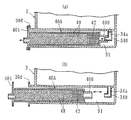
図2によく表われているように、分離処理槽4Aは、底部、複数の側壁部、および上壁部を有する略ボックス状であり、前記上壁部には、下向きに延びた断面略V字状の仕切壁41Aが形成されている。この仕切壁41Aによって、分離処理槽4A内は、底部どうしが連通部46Aを介して互いに連通した第1および第2のチャンバ43a,43bに仕切られている。第1のチャンバ43aの上部には、ドレインの流入口45aが設けられている。第2のチャンバ43bのうち、中和処理槽4Bと連接する側壁には、第2のチャンバ43bから中和処理槽4Bにドレインを流出させるための流通口45bが設けられている。この流通口45bは、分離処理槽4Aの底部から適当な高さHaに設けられており、このことにより分離処理槽4A内においては、流入口45aから流入したドレインがHa以下の液面高さで貯留され、それを超えるとドレインは流通口45bから中和処理槽4Bに流入する。
As clearly shown in FIG. 2, the
第1のチャンバ43a内に、燃料オイルやその他の夾雑物が混入したドレインが流入すると、比重の軽いオイルや夾雑物がドレイン上に浮き、図2に示すようにそれらの層Flが形成される。また、比重の重い夾雑物は、沈殿物mとなる。一方、第1および第2のチャンバ43a,43bどうしの上部寄り領域は、仕切壁41Aによって仕切られている。したがって、ドレイン上に浮いているオイルや夾雑物は、そのまま第1のチャンバ43aから第2のチャンバ43bに向けて流入することはなく、第1のチャンバ43a内に捕捉されたままとなる。第1のチャンバ43aの底部の沈殿物mは、連通部46Aを通過して第2のチャンバ43bに流入する虞れがあるものの、流通口45bは底部から一定の高さHaを隔てて設けられているために、この沈殿物mが中和処理槽4Bに流入することもない。このような原理により、燃料オイルや夾雑物はこの分離処理槽4A内において捕捉される。
When a drain mixed with fuel oil or other contaminants flows into the
オイル吸着フィルタ42は、第2のチャンバ43b内に設けられている。既述したとおり、ドレインに混入したオイルは、第1のチャンバ43a内に捕捉されるものの、第1のチャンバ43a内へのドレインの流入の仕方によっては、オイルが第2のチャンバ43bに流れ込む場合があり、このオイル吸着フィルタ42はそのようなオイルを捕捉するのに役立つ。また、分離処理槽4A内にある程度の量のドレインが貯留されている定常状態では、既述したようにオイルをドレイン上に浮かせて分離させることが可能であるものの、この分離処理槽4A内が空とされている使用初期時において、ドレインが第1のチャンバ43aに流入した場合には、オイルもドレインと一緒に第2のチャンバ43bに流入する虞れがある。オイル吸着フィルタ42は、そのような使用初期時において第2のチャンバ43bに流入してきたオイルを捕捉する役割をも発揮する。
The
オイル吸着フィルタ42の具体例を挙げると、繊維状活性炭や、やしがら活性炭などの各種の活性炭、カポック繊維などの植物性繊維、ポリプロピレンなどの高分子ポリマの化学繊維、あるいは炭化水素の粒状体など、基本的には、オイルの吸着性に優れ、かつ水の吸着性が劣るものであれば、種々の材質のものを用いることができる。オイル吸収時に膨潤するタイプのものを用いることもできる。オイル吸着フィルタ42は、繊維状、シート状、綿状、あるいは粒状であるなど、その具体的な形態を問うものではない。前記素材が繊維状や粒状などである場合には、好ましくは、これらの素材を通水性を有する容器(袋も含む)に収容させておき、この容器を第2のチャンバ43b内に装着した構成とされている。第2のチャンバ43bの上壁部には、蓋付きの開口部43b'が設けられており、この開口部43b'がオイル吸着フィルタ42の出し入れ口となっている。
Specific examples of the
分離処理槽4Aの第1のチャンバ43aには、ドレインの液面レベルセンサ97や排出口47aも設けられている。液面レベルセンサ97は、第1のチャンバ43aよりも下流側に詰まりなどを生じることに起因して分離処理槽4A内のドレインの液面レベルが前記の高さHaを一定以上超えた異常高さとなったときにこれを検出するものであり、その検出信号は、この給湯装置A1の運転を制御する制御部(図示略)に送信されるようになっている。この液面レベルセンサ97は、たとえば第1のチャンバ43a内において高さHaよりも上方に配された一対の電極97aを有しており、ドレインの液面が上昇してドレイン中に一対の電極97aが浸漬すると、それら電極97a間が通電し、所定の信号が出力される構造を有している。排出口47aは、分離処理槽4Aの底部に設けられており、ネジ部材などの栓体47bによって常時は閉塞されている。栓体47bを外してこの排出口47aを開くと、分離処理槽4A内のドレインを外部に抜き取ることが可能である。これは、たとえばこの給湯装置A1を長期間不使用とする場合に好適であり、とくに冬季において分離処理槽4A内に貯留されているドレインが凍結するといったことを防止するのに好適となる。また、後述するように、第1のチャンバ43aは、燃料オイルや夾雑物を捕捉する役割を果たすが、排出口47aは、それらを外部に排出させて第1のチャンバ43a内を清浄にするのにも好適となる。
A
中和処理槽4Bは、中和剤48を内部に収容した略ボックス状であるが、この中和処理槽4Bもオイル捕捉機能を有するように構成されている。より具体的には、この中和処理槽4Bは、底部、複数の側壁部、および上壁部を有しており、上壁部には、中和剤48を内部に投入するための蓋付きの開口部43c',43d'が設けられている。また、前記上壁部には、下向きに延びた仕切壁41Bが形成されており、この仕切壁41Bによって、中和処理槽4Bの内部は、底部どうしが連通部46Bを介して互いに連通した第1および第2のチャンバ43c,43dに仕切られている。第1のチャンバ43c内には、分離処理槽4Aを通過してきたドレインが流通口45bから流入する。これに対し、第2のチャンバ43dは、ドレイン流れ方向の下流寄りの側壁に流出口45cを備えているが、この流出口45cは、前記した高さHaよりもやや低い高さとされ、この中和処理槽4Bにおいてはドレインをそれ以下の液面高さで収容可能である。前記ドレインは、その液面レベルがそれ以上になると、流出口45cからドレイン流通管50に流入する。
The
第1のチャンバ43cは、分離処理槽4Aにおける第1のチャンバ43aと同様な原理によりオイル捕捉を行なうようになっている。すなわち、第1のチャンバ43cにドレインが流入すると、このドレインに混入しているオイルはドレイン上に浮き、第2のチャンバ43dに流入することが仕切壁41Bによって抑制される。その結果、第1のチャンバ43c内には、前記オイルが捕捉されたままとなる。オイル以外の夾雑物についても、第1のチャンバ43aについて述べたのと同様な原理で分離し、かつこの中和処理槽4B内に捕捉させておくことが可能である。
The
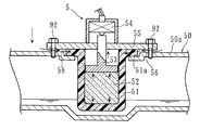
オイルセンサ5は、中和処理槽4Bの流出口45cからドレイン流通管50に流入したドレイン内にオイルが残存しているか否かを判断するためのものである。また、このオイルセンサ5は、後述するように、燃焼器1の燃料供給部15から燃料オイルが漏出した場合にこれを検出する機能をも有している。このオイルセンサ5は、図4に示すように、ケーシング51内にオイル膨潤物質52が収容された構成を有している。ケーシング51は、疎水性、親油性および透油性を有するたとえば多孔質の焼結樹脂製である。オイル膨潤物質52は、たとえばシリコン樹脂パウダからなる。このオイルセンサ5においては、ドレイン流通管50内を流れるドレインにオイルが混入していると、このオイルがケーシング51を透過してオイル膨潤物質52がこれを吸収する結果、このオイル膨潤物質52の体積が増加し、ケーシング51内に別途設けられている可動部材53を上昇させる。すると、その上方に設けられていた検出スイッチ54が可動部材53との接触によってオンとなり、オイル検出の旨の信号が前記制御部に入力されるようになっている。
The
また、オイルセンサ5は、ケーシング51の上部のフランジ部51aがベース部材55に接合され、かつこのベース部材55がボルト92によってドレイン流通管50の上壁部50aに固定されているが、この上壁部50aとベース部材55との間には、オイルの通過を可能とする隙間56が形成されている。この構造により、このオイルセンサ5は、燃焼器1の燃料供給部15において燃料オイル漏れが万一発生し、この燃料オイルが上壁部50a上に落下してきた場合には、この燃料オイルが隙間56を通過してケーシング51の内部に進入することにより、この燃料オイルをも検出できるようになっている。図1によく表われているように、ドレイン流通管50は、底部ケーシング3の下方からその一側方にはみ出しており、その上方の燃料供給部15において燃料オイル漏れが発生した場合には、この燃料オイルを適切に受けることができるように設けられている。好ましくは、このドレイン流通管50は、平面視において広い面積をもつように、図1の紙面と直交する方向に比較的大きな幅を有しており、また上壁部50aに燃料オイルが落下してきた場合には、この燃料オイルを隙間56に適切に導くことができるように、上壁部50aの全体または一部分は凹状とされている。さらに好ましくは、前記凹状部分は、オイルセンサ5寄りになるほどその高さが低くなるように、その上向き面が傾斜した構成とされている。
Further, the
次に、上記したドレイン処理装置B1および給湯装置A1の作用について説明する。 Next, the operation of the drain processing device B1 and the hot water supply device A1 will be described.
まず、燃焼器1を駆動させて燃料オイルを燃焼させると、この燃焼ガスは送風ファン13からの送風作用により下方に向けて進行し、1次熱交換部2Aによりその顕熱が回収され、また底部ケーシング3内に進行した際には、2次熱交換部2Bにより潜熱が回収される。2次熱交換部2Bを底部ケーシング3内に設けた構成によれば、底部ケーシング3の外部に2次熱交換部2Bを積層して設ける構成と比較すると、給湯装置A1全体の小型化および部品点数の減少を図ることができる。また、2次熱交換部2Bにおいては、多くのドレインが発生するが、このドレインは底部ケーシング3の底板部34上に滴下し、排出口34aからドレイン処理装置B1に対して迅速に、かつ円滑に送り込まれる。このため、燃焼ガス流路の内壁の広い領域にわたってドレインが付着し、残留したままになるといったことが適切に回避される。燃焼器1の運転やその停止に伴い、燃料への着火不良などを生じると、未燃焼の燃料オイルがドレインに混入することとなる。噴霧ノズル10は、下向きに燃料オイルを噴射しており、未燃焼の燃料オイルは底部ケーシング3に溜まり易い構造とされているために、この給湯装置A1では、未燃焼の燃料オイルをドレインを利用して底部ケーシング3の下方に円滑に排出させるようになっており、燃焼ガス流路内に未燃焼の燃料オイルが多く溜まらないようにするのにも好適となる。
First, when the combustor 1 is driven to burn the fuel oil, the combustion gas proceeds downward by the air blowing action from the
次いで、ドレイン処理装置B1に送り込まれたドレインは、分離処理槽4A、中和処理槽4Bおよびドレイン流通管50を経由して外部に排出される。この場合、既述したとおり、まず分離処理槽4Aによれば、第1のチャンバ43a内において比重の軽い燃料オイルやその他の夾雑物がドレイン上に浮き、これらが第2のチャンバ43b内に流れ込むことが仕切壁41Aの存在により抑制され、第1のチャンバ43a内に捕捉される。比重の重い夾雑物については、第1および第2のチャンバ43a,43bの底部に沈殿させておくことにより、やはりこれらが中和処理槽4Bに流れ込まないようにすることができる。また、仮に第2のチャンバ43b内に燃料オイルが流れ込んだ場合であっても、この燃料オイルはオイル吸着フィルタ42に吸着され、適切に捕捉される。オイル吸着フィルタ42は、固形の夾雑物が通過することを阻害し、捕捉する機能をも発揮する。したがって、中和処理槽4B内に燃料オイルやその他の夾雑物が流入することがより確実に防止される。
Next, the drain sent to the drain processing apparatus B1 is discharged to the outside via the
さらに、中和処理槽4Bにおいても、既に述べたとおり、第1のチャンバ43cにおいて燃料オイルをドレイン上に浮かし、この燃料オイルが下流側に流れることを仕切壁41Bによって抑制することができる。したがって、燃料オイルが中和処理槽4Bよりも下流側に流れることが徹底して防止される。その結果、中和剤48によって中和され、かつオイルや夾雑物を含まないドレインを外部に排出して廃棄することが可能となり、環境保護の観点から好ましいものとなる。また、中和処理槽4Bにおいて、ドレインが第1のチャンバ43cから連通部46Bを通過して第2のチャンバ43dに流れる場合、前記ドレインは仕切壁41Bの下方を潜るような経路を辿る。したがって、中和処理槽4B内におけるドレインの流路長を長くとってドレインを多くの中和剤48に触れさせ、その中和処理を効率良く行なわせる効果も得られることとなる。
Furthermore, also in the
給湯装置A1の通常の稼働状態では、たとえば燃料オイルへの着火不良などに起因して未燃焼の燃料オイルが発生しても、その量は僅かである。したがって、たとえば10年あるいはそれ以上の長期間にわたって給湯装置A1を使用する場合であっても、たとえばオイル吸着フィルタ42を一度も交換する必要のないいわゆるメンテナンスフリーとし、その下流には燃料オイルが流れないようにすることが可能である。ところが、実際の使用に際しては、予測困難な要因により燃焼器1が故障するなどして、多くの燃料オイルが底部ケーシング3内に流出する事態の発生を想定し得る。このような事態が生じた場合には、もはやオイル吸着フィルタ42やその他の上記したオイル捕捉手段によっては燃料オイルの全量を捕捉することが困難となる場合がある。これに対し、この給湯装置A1においては、そのような異常事態が生じると、オイルセンサ5によってドレイン流通管50内を流れる燃料オイルが検出され、その旨の報知がなされるために、ユーザはこのことによって直ちに前記の異常を察知し、適切な処置を採ることができることとなる。前記燃料オイルの検出に基づき、燃焼器1を緊急停止させるといった制御を行なわせることもできる。なお、前記とは異なり、たとえばオイル吸着フィルタ42や分離処理槽4Aを比較的小サイズに形成し、適当な期間ごとにオイル吸着フィルタ42を交換する仕様とした場合には、前記したオイルセンサ5によるオイル検出によって、オイル吸着フィルタ42の交換時期を察知させるといった使い方も可能となる。オイルセンサ5は、既述したとおり、燃焼器1の燃料供給経路において燃料オイル漏れなどが生じた場合には、この燃料オイルをドレイン流通管50の上壁部50aによって受け、かつこれを検出できるように設けられている。したがって、この給湯装置A1においては、前記したような燃料オイルの漏れを検出する専用のセンサを別途設ける必要がなく、製造コストを低減するのにより好適である。
In the normal operation state of the water heater A1, even if unburned fuel oil is generated due to, for example, poor ignition of the fuel oil, the amount is small. Therefore, for example, even when the hot water supply device A1 is used for a long period of 10 years or longer, for example, the
図5〜図12は、本発明の他の実施形態を示している。なお、これらの図において、前記実施形態と同一または類似の要素には、前記実施形態と同一の符号を付している。 5 to 12 show other embodiments of the present invention. In these drawings, the same or similar elements as those of the above embodiment are denoted by the same reference numerals as those of the above embodiment.
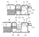
図5(a)に示すドレイン処理装置においては、分離処理槽4Aの仕切壁41Aの直下の底部に、上向きの仕切壁41aが設けられており、それら一対の仕切壁41A,41a間に形成された連通部46Aを介して第1および第2のチャンバ43a,43bが連通している。連通部46Aは、第1および第2のチャンバ43a,43bの底部よりもやや高い部分どうしを連通させており、仕切壁41aは、第1のチャンバ43aの底部の沈殿物mが第2のチャンバ43bに流入することを抑制する役割を果たす。本実施形態から理解されるように、連通部46Aは、第1および第2のチャンバ43a,43bの底部どうしを連通させる構成に代えて、または加えて、第1および第2のチャンバ43a,43bの高さ方向中間部どうしを連通させる構成とされていてもかまわない。もちろん、中和処理槽4Bに設けられる連通部46Bについても同様である。なお、仕切壁41aを設けた場合には、排出口47aを開いた場合にこの仕切壁41aが邪魔となって第2のチャンバ43b内のドレインの全量を排出口47aから抜くことができない。したがって、このような場合には、第2のチャンバ43bの底部にも、排出口47aと同様なドレイン抜き用の排出口を設けることが好ましい。
In the drain treatment apparatus shown in FIG. 5 (a), an
図5(b)に示すドレイン処理装置においては、分離処理槽4Aの仕切壁41Aが、底面部410と、この底面部410の両側端縁から立ち上がった一対の起立面部411とを有する断面略U字状または略コ字状とされている。このことにより、第1および第2のチャンバ43a,43bは底面部410の幅Lと同一の比較的大きな寸法で離間しており、連通部46Aは幅Lと同一長さのトンネル状となっている。このような構成であっても、先に述べた実施形態と同様な原理により、第1のチャンバ43a内においてドレインよりも比重の軽い燃料オイルや他の夾雑物を捕捉することが可能である。これまで述べた実施形態においては、たとえばブロー成形された容器40の一部分をそのまま仕切壁41Aとして突出させているために、仕切壁41Aが断面略V字状あるいは略U字状に折り返された形状となっているが、本発明はこれに限定されない。本発明は、分離処理槽4Aを構成する容器とは別部材を利用して仕切壁41Aを形成してもかまわず、折り返しのない単なる平板状などに形成することもできることは勿論である。また、第1および第2のチャンバ43a,43bが別部材により形成され、かつこれらがたとえば筒状部材によって接続されていることにより、前記筒状部材の内部が連通部46Aとされた構成とすることもできる。中和処理槽4Bの仕切壁41Bや第1および第2のチャンバ43c,43dについても、前記と同様である。
In the drain processing apparatus shown in FIG. 5B, the
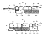
図6(a)に示すドレイン処理装置においては、分離処理槽4Aが中和処理槽4Bの後段(ドレイン流れ方向の下流側)に配されている。ドレインは、流入口45dから中和処理槽4Bに流入して中和処理された後に、流通口45eを通過して分離処理槽4A内に流入し、その後排出口45fを通過してドレイン流通管50に流入するようになっている。液面レベルセンサ97は、ドレイン処理装置の最上流位置に設けることが好ましく、本実施形態においては中和処理槽4Bの第1のチャンバ43cに設けられている。中和処理槽4Bは、第1のチャンバ43cにおいてオイルを捕捉する機能を有しているものの、これだけでは捕捉されない燃料オイルはその後分離処理槽4Aにおいて適切に捕捉されることとなる。本実施形態においては、燃料オイルが中和剤48に付着する虞れがあるものの、中和剤48の中和処理機能は燃料オイルの付着によって大きく劣化することはなく、ドレインの中和処理を適切に行なうことが可能である。ただし、中和処理槽4B内に燃料オイルや夾雑物が累積して目詰まりが発生することを防止する観点からすれば、分離処理槽4Aを中和処理槽4Bの前段に設けることが好ましい。
In the drain treatment apparatus shown in FIG. 6 (a), the
図6(b)に示すドレイン処理装置においては、分離処理槽4Aにオイル吸着フィルタ42が設けられておらず、中和処理槽4Bの後段に連設されたチャンバ43eにオイル吸着フィルタ42が設けられている。このような構成によっても、先に述べた実施形態と同様にドレインの中和処理と燃料オイルやその他の夾雑物の排除とが適切に行なわれる。本実施形態に示す分離処理槽4Aから理解されるように、本発明でいう分離処理槽は、ドレインとの比重差を利用して燃料オイルを分離させて捕捉し得る機能を有していればよく、オイル吸着フィルタ42が設けられていない構成としてもかまわない。図6(b)に示すドレイン処理装置の構成のうち、分離処理槽4Aとオイル吸着フィルタ42とは、いずれも本発明でいうオイル捕捉手段の一例に相当している。したがって、本発明においては、同図に示す構成のうち、オイル吸着フィルタ42を具備することなく、分離処理槽4Aと中和処理槽4Bとを組み合わせただけの構成、または分離処理槽4Aを具備することなく、中和処理槽4Bとオイル吸着フィルタ42とを組み合わせただけの構成とすることもできる。
In the drain treatment apparatus shown in FIG. 6B, the
図7に示すドレイン処理装置においては、中和処理槽4B内のうち、仕切壁41Bよりも下流側に、この中和処理槽4Bの底部から上向きに起立した起立壁41bが設けられている。このような構成によれば、仕切壁41Bの下方の連通部46Bを通過して第2のチャンバ43dの上流側領域に流入したドレインは、起立壁41bを越えることによって第2のチャンバ43dの下流側領域に流入する。したがって、ドレインの実質的な流路長を長くとり、中和剤48による中和処理を効率良く行なわせることができる。起立壁41bを複数設ければ、ドレインの流路長をさらに長くすることができる。
In the drain treatment apparatus shown in FIG. 7, an
図8に示すドレイン処理装置においては、略ボックス状に形成されたドレイン流通槽50Aが、容器40の一部分を利用して形成されている。より具体的には、ドレイン流通槽50Aは、中和処理槽4Bや分離処理槽4Aと一体的にブロー成形などの手法によって樹脂成形されている。このドレイン流通槽50A内には、オイルセンサ5が装着されている。本実施形態によれば、ドレイン流通管50を別途製作して容器40に接続させていた先の実施形態の構成と比較すると、ドレイン処理装置全体の製造作業が容易化される。先の実施形態においては、燃焼器1の燃料供給部15に燃料オイル漏れが生じた場合にオイルセンサ5がこれを検出するように構成されていたが、本実施形態においては、そのような機能を有しておらず、オイルセンサ5は中和処理槽4Bから流出してきたドレイン内に混入しているオイルを検出する機能を有するのみである。オイルセンサとしては、従来から種々の構造のものが開発され、また市販されている実情もあり、それらのいずれを採用してもよいことは勿論である。
In the drain processing apparatus shown in FIG. 8, a
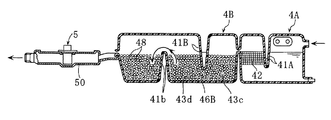
図9(a)に示すドレイン処理装置は、カートリッジタイプの容器40Aを備えており、この容器40A内の一端寄りの領域にはオイル吸着フィルタ42が収容され、それ以外の残余の領域には中和剤48が充填されている。この容器40Aは、底部ケーシング3の下部または下方の空間スペース91内に取り外し可能に収容されている。容器40Aの先端部に設けられた接続口400は、底部ケーシング3の排出口34aを形成する管体部340に対して嵌脱自在であり、同図(b)に示すように、容器40Aを管体部340から離隔させた状態において容器40Aを管体部340に向けて前進させることによって接続口400を管体部340に対して容易に嵌合接続できるようになっている。容器40Aの基端部には、底部ケーシング3に設けられたフランジ部30dに連結させるためのフランジ部401が連設されており、これらをボルト止めすることによって、容器40Aの固定が図られている。
The drain processing apparatus shown in FIG. 9 (a) includes a
本実施形態においては、ドレイン処理装置全体の構造を簡素とし、廉価にすることができる。したがって、たとえばオイル吸着フィルタ42や中和処理槽4Bの中和剤48を交換する必要が生じて、それらを容器40Aごと新しいものと交換する場合のユーザの費用負担を少なくすることができる。容器40Aを底部ケーシング3の排出口34aに接続する作業およびその解除作業が容易であるため、前記交換作業も簡単である。本実施形態から理解されるように、本発明に係るドレイン処理装置は、1つの容器に中和剤とオイル吸着フィルタとを収容させただけの非常に簡素な構成とすることもできる。
In the present embodiment, the structure of the entire drain processing apparatus can be simplified and made inexpensive. Therefore, for example, it becomes necessary to replace the
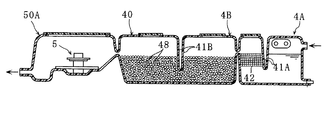
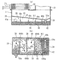
図10に示す給湯装置A2においては、底部ケーシング3内に2次熱交換部2Bが設けられておらず、2次熱交換部2Bは、1次熱交換部2Aの缶体20と底部ケーシング3との間に挟まれた缶体20Bと、この缶体20B内を横切るように設けられた管体22cとを備えた構成とされている。管体22cは、複数のフィン24bを備えており、これらは耐食性に優れたたとえばステンレス製である。この熱交換器HTにおける通水の仕方は、先の実施形態のものと同様であり、入水口21aに入水された水は、2次熱交換部2Bの管体22cを通過した後に、1次熱交換部2Aの管体22a,22bを通過して出湯口21bから排出されるようになっている。本実施形態で示すような構成の2次熱交換部2Bによっても燃焼ガスの潜熱回収が可能であり、本発明においてはこのような構成を採用することもできる。
In the hot water supply device A2 shown in FIG. 10, the secondary
また、図10に示す構成においては、ドレイン処理装置B2のオイル吸着フィルタ42や中和剤48を収容する収容部49が、底部ケーシング3と一体に形成されている。より具体的には、底部ケーシング3は、排出口34aを有する底板部34よりも下方に延設された複数の側壁部39と、これら側壁部39の底部開口を塞ぐ追加の底板部38とを備えており、これらによって底板部34の下方に収容部49が形成されている。この収容部49のうち、排出口34aの下方およびその周辺部分には、オイル吸着フィルタ42が配されており、またその隣の領域は中和剤48が収容された中和処理槽4Bとなっている。オイル吸着フィルタ42と中和処理槽4Bとの間は、仕切壁49aによって仕切られており、オイル吸着フィルタ42の配置領域に流入したドレインは、仕切壁49aを越えることによって中和処理槽4Bに流入し、その後流出口45gから外部に流出するようになっている。
Further, in the configuration shown in FIG. 10, an
本実施形態においては、底部ケーシング3を利用してドレイン処理装置B2を構成しているために、先に述べた実施形態とは異なり、ドレイン処理装置専用の容器を別途用いる必要が無くなる。本実施形態から理解されるように、本発明はドレイン処理装置を給湯装置内に一体的に造り込んだ構成としてもかまわない。
In the present embodiment, since the drain processing apparatus B2 is configured by using the
図11に示す構成においては、ドレイン処理装置B2の収容部49内に複数の仕切壁49b,49cが設けられている。仕切壁49bは、収容部49の幅方向(同図(a)の紙面と直交する方向)に延びているものの、この収容部49の全幅よりも短い寸法とされ、同図(b)に示すように、オイル吸着フィルタ42の配置領域と中和処理槽4Bとの間に連通路490aを形成している。複数の仕切壁49cも、それと同様であり、中和処理槽4B内に複数の連通路490bを形成している。ただし、これら複数の連通路490bは、ドレインが蛇行して流れるように、平面視において互い違い状の配置となっている。底部ケーシング3の排出口34aは、収容部49の幅方向において連通路490aの形成箇所とは反対側に設けられている。
In the configuration shown in FIG. 11, a plurality of
本実施形態によれば、オイル吸着フィルタ42内および中和処理槽4B内におけるドレインの流路長を長くとることができる。したがって、収容部49の全体のサイズをさほど大きくすることなく、燃料オイルの捕捉やドレインの中和処理を十分に行なわせることが可能となる。
According to the present embodiment, the drain flow path length in the
図12に示す構成においては、2つの中和処理槽4Bの間にオイル吸着フィルタ42が配されている。本実施形態によれば、排出口34aから一方の中和処理槽4B内に流入したドレインは、オイル吸着フィルタ42を通過した後に他方の中和処理槽4B内に流入する。本発明においては、本実施形態のように中和処理槽4Bを複数に分断させたかたちで設けてもよいし、またオイル吸着フィルタ42をそれらの間に介在させるように設けてもよい。ドレイン処理装置は、給湯装置において発生するドレインを一般の排水経路に流出させるまでの経路中において、ドレインに混入している燃料オイルを捕捉して除去できればよく、オイル吸着フィルタなどのオイル捕捉手段は、中和処理槽の上流側、下流側、あるいはその中間部分のいずれに設けられていてもかまわない。もちろん、オイル吸着フィルタを収容する部材と中和剤を収容する部材とが別体で形成され、これらが配管などを介して接続された構成とされていてもかまわない。したがって、底部ケーシング3の下部に設けられた収容部49には、オイル吸着フィルタ42のみが収容され、かつ中和処理槽4Bがその外部に外付けされて接続された構成、あるいはこれとは反対に、収容部49には中和剤48のみが収容され、かつオイル吸着フィルタ42がその外部に外付けされて接続された構成とすることもできる。
In the configuration shown in FIG. 12, an
本発明は、上述した実施形態に限定されない。本発明に係るドレイン処理装置を備えた給湯装置の各部の具体的な構成は、種々に設計変更自在である。 The present invention is not limited to the embodiment described above. The specific configuration of each part of the hot water supply apparatus including the drain treatment apparatus according to the present invention can be varied in design in various ways.
たとえば、中和処理槽については、固形の中和剤を収容した構成とすることが最も簡易であるが、これに代えて、たとえば液体状の中和剤をドレインに混入させて中和処理を行なうといった構成にすることも可能である。オイル捕捉手段としては、前述した実施形態から理解されるように、オイル吸着フィルタとドレインとの比重差を利用して分離捕捉させる手段とを組み合わせて、あるいはそれらの一方を単独で用いることが可能であるが、本発明はこれに限定されず、オイルをドレインから分離させて捕捉し得る手段であれば、種々の手段を適用することが可能である。 For example, for the neutralization tank, it is simplest to have a structure containing a solid neutralizer, but instead of this, for example, a liquid neutralizer is mixed into the drain for neutralization treatment. It is also possible to adopt a configuration such as performing. As understood from the above-described embodiments, the oil trapping means can be used in combination with a means for separating and trapping using the difference in specific gravity between the oil adsorption filter and the drain, or one of them can be used alone. However, the present invention is not limited to this, and various means can be applied as long as the oil can be separated from the drain and captured.
燃焼器は、燃料オイルを噴霧して燃焼させるものに代えて、たとえば燃料オイルを気化させてから燃焼させる構造とすることもできる。また、本発明に係る給湯装置は、いわゆる瞬間式の給湯器として構成できることは勿論のこと、それ以外の床暖房や融雪用途など、種々の用途に湯を供給するための装置として構成することができる。なお、本発明でいう燃料オイルとは、灯油や軽油などの石油あるいは石油の分留成分としてのオイル、および石油以外から生成される燃焼用の油を含む広い概念である。 The combustor may have a structure in which the fuel oil is vaporized and combusted instead of the fuel oil sprayed and combusted, for example. In addition, the hot water supply apparatus according to the present invention can be configured as a so-called instantaneous water heater, and can be configured as an apparatus for supplying hot water to various uses such as other floor heating and snow melting applications. it can. The fuel oil in the present invention is a broad concept including petroleum such as kerosene and light oil, oil as a fractional component of petroleum, and combustion oil generated from other than petroleum.
A1,A2 給湯装置
B1,B2 ドレイン処理装置
HT 熱交換器
1 燃焼器
2A 1次熱交換部(熱交換器)
2B 2次熱交換部(熱交換器)
3 底部ケーシング(ケーシング)
4A 分離処理槽
4B 中和処理槽
5 オイルセンサ
34 底板部
34a 排出口
40 容器
41A,41B 仕切壁
42 オイル吸着フィルタ
43a 第1のチャンバ(分離処理槽の)
43b 第2のチャンバ(分離処理槽の)
43c 第1のチャンバ(中和処理槽の)
43d 第2のチャンバ(中和処理槽の)
46A,46B 連通部
47a 排出口
48 中和剤
91 空間スペース
A1, A2 Hot water supply device B1, B2 Drain treatment device HT Heat exchanger 1
2B Secondary heat exchange section (heat exchanger)
3 Bottom casing (casing)
4A
43b Second chamber (for separation treatment tank)
43c First chamber (for neutralization tank)
43d Second chamber (of neutralization tank)
46A,
Claims (3)
この燃焼器によって発生された燃焼ガスを下向きに進行させてから略U字状に屈曲または湾曲した底部を介して上向きに進行させて排気口まで流通させる燃焼ガス流路と、
前記燃焼器の下方領域において前記燃焼ガスとの熱交換を行なう通水用の管体を有する熱交換器と、
前記熱交換によって発生するドレインを中和するための中和処理槽を有するドレイン処理装置と、
を備えている、給湯装置であって、
前記燃焼ガス流路の底部には、前記熱交換器から落下するドレインを受けて一定の箇所に集めることが可能な傾斜面を有する底板部と、この底板部によって一定の箇所に集められたドレインを前記燃焼ガス流路の外部に排出させる排出口とが設けられているとともに、前記底板部の下方には、空間スペースが形成されており、
前記ドレイン処理装置は、少なくともその一部分が前記空間スペース内に位置して、前記排出口から排出されるドレインを受けるように設けられ、かつ前記ドレインに燃料オイルが混入しているときに、前記ドレインが前記中和処理槽に流入する前または後の段階において、前記燃料オイルを捕捉可能なオイル捕捉手段を備えていることを特徴とする、ドレイン処理装置を備えた給湯装置。 A combustor that burns fuel oil downward;
A combustion gas flow path for causing the combustion gas generated by the combustor to flow downward and then to flow upward through a bottom portion bent or curved in a substantially U shape to flow to the exhaust port;
A heat exchanger having a water passage tube for performing heat exchange with the combustion gas in a lower region of the combustor;
A drain treatment apparatus having a neutralization treatment tank for neutralizing the drain generated by the heat exchange;
A hot water supply device comprising:
At the bottom of the combustion gas flow path, there is a bottom plate portion having an inclined surface that can be collected at a certain location by receiving a drain falling from the heat exchanger, and the drain collected at a certain location by the bottom plate portion And a discharge port for discharging the gas to the outside of the combustion gas flow path, and a space is formed below the bottom plate portion,
The drain processing device is provided so that at least a portion thereof is located in the space and receives the drain discharged from the discharge port, and when the fuel oil is mixed in the drain, the drain processing device A hot water supply apparatus equipped with a drain treatment apparatus, comprising oil capture means capable of capturing the fuel oil before or after flowing into the neutralization treatment tank.
Priority Applications (2)
| Application Number | Priority Date | Filing Date | Title |
|---|---|---|---|
| JP2004291859A JP4604635B2 (en) | 2004-10-04 | 2004-10-04 | Hot water supply device equipped with a drain treatment device |
| PCT/JP2005/017653 WO2006038482A1 (en) | 2004-10-04 | 2005-09-26 | Water heating device and drain neutralizing device |
Applications Claiming Priority (1)
| Application Number | Priority Date | Filing Date | Title |
|---|---|---|---|
| JP2004291859A JP4604635B2 (en) | 2004-10-04 | 2004-10-04 | Hot water supply device equipped with a drain treatment device |
Publications (2)
| Publication Number | Publication Date |
|---|---|
| JP2006102617A JP2006102617A (en) | 2006-04-20 |
| JP4604635B2 true JP4604635B2 (en) | 2011-01-05 |
Family
ID=36372918
Family Applications (1)
| Application Number | Title | Priority Date | Filing Date |
|---|---|---|---|
| JP2004291859A Expired - Fee Related JP4604635B2 (en) | 2004-10-04 | 2004-10-04 | Hot water supply device equipped with a drain treatment device |
Country Status (1)
| Country | Link |
|---|---|
| JP (1) | JP4604635B2 (en) |
Families Citing this family (12)
| Publication number | Priority date | Publication date | Assignee | Title |
|---|---|---|---|---|
| DE102006051190A1 (en) * | 2006-08-10 | 2008-02-14 | Mommertz Wasser- und Wärmetechnik GmbH | neutralizer |
| JP2009011948A (en) * | 2007-07-05 | 2009-01-22 | Gastar Corp | Drain foreign matter removing structure and drain neutralizer using the drain foreign matter removing structure |
| JP5382398B2 (en) * | 2007-08-20 | 2014-01-08 | 株式会社ノーリツ | Neutralizing device and hot water supply device |
| JP5077669B2 (en) * | 2007-10-30 | 2012-11-21 | 株式会社ノーリツ | Water seal device and latent heat recovery hot water supply device |
| JP2009150576A (en) * | 2007-12-19 | 2009-07-09 | Noritz Corp | Water heating system equipped with neutralizer |
| JP5182570B2 (en) * | 2008-06-25 | 2013-04-17 | 株式会社ノーリツ | Water heater |
| JP5212703B2 (en) * | 2008-06-25 | 2013-06-19 | 株式会社ノーリツ | Water heater |
| JP5256882B2 (en) * | 2008-06-25 | 2013-08-07 | 株式会社ノーリツ | Water heater |
| US8973366B2 (en) * | 2011-10-24 | 2015-03-10 | General Electric Company | Integrated fuel and water mixing assembly for use in conjunction with a combustor |
| JP5758319B2 (en) * | 2012-02-13 | 2015-08-05 | 株式会社コロナ | Neutralizer and hot water supply apparatus having the same |
| US11565955B2 (en) * | 2018-09-28 | 2023-01-31 | Neutrasafe Llc | Condensate neutralizer |
| CZ34269U1 (en) * | 2020-06-16 | 2020-08-11 | ALMEVA EAST EUROPE s.r.o. | Neutralization box |
Family Cites Families (6)
| Publication number | Priority date | Publication date | Assignee | Title |
|---|---|---|---|---|
| JPS59123594A (en) * | 1982-12-29 | 1984-07-17 | Kogata Gas Reibou Gijutsu Kenkyu Kumiai | Neutralization apparatus |
| JPH0632164Y2 (en) * | 1987-05-20 | 1994-08-24 | 三洋電機株式会社 | Exhaust gas drain water treatment device |
| JPH06212965A (en) * | 1993-01-14 | 1994-08-02 | Tokyo Gas Co Ltd | Exhaust drain neutralizer for engine |
| JP2902907B2 (en) * | 1993-06-22 | 1999-06-07 | 三洋電機株式会社 | Exhaust gas drain water treatment equipment |
| JPH11309465A (en) * | 1998-04-28 | 1999-11-09 | Noritz Corp | Neutralizing device |
| JP3835338B2 (en) * | 2002-04-25 | 2006-10-18 | 株式会社ノーリツ | Drain neutralization tank |
-
2004
- 2004-10-04 JP JP2004291859A patent/JP4604635B2/en not_active Expired - Fee Related
Also Published As
| Publication number | Publication date |
|---|---|
| JP2006102617A (en) | 2006-04-20 |
Similar Documents
| Publication | Publication Date | Title |
|---|---|---|
| JP4604635B2 (en) | Hot water supply device equipped with a drain treatment device | |
| EP1650162A1 (en) | System and method for collecting carbon dioxide in exhaust gas | |
| JP4980130B2 (en) | Neutralizer and system for drain | |
| KR20130117042A (en) | Trap apparatus for condensate water and drain apparatus for condensate water installed on the same | |
| JP2017110629A (en) | Next generation fuel pump integrated diesel fuel filter | |
| KR20100019258A (en) | Incineration boiler | |
| JP4265518B2 (en) | Water heater | |
| JP2006105467A (en) | Hot water supply device | |
| CN102588989B (en) | Smoke spraying and purifying heat recovery system of gas boiler as well as gas and fuel oil burning device | |
| JP3989163B2 (en) | Water heater | |
| WO2006095660A1 (en) | Condensed-water neutralizer and hot-water-supply apparatus equipped therewith | |
| JP4815779B2 (en) | Water heater | |
| WO2006038482A1 (en) | Water heating device and drain neutralizing device | |
| JP4222283B2 (en) | Oil detection device and hot water supply device having the same | |
| JP4978330B2 (en) | Neutralizing device, combustion device, and hot water supply device | |
| JP5207087B2 (en) | Water heater | |
| CN212532875U (en) | Light hydrocarbon recovery and oil-water separation device of triethylene glycol regeneration system | |
| JP4978328B2 (en) | Neutralizing device, combustion device, and hot water supply device | |
| JP5058210B2 (en) | Combustor neutralizer | |
| JP2009172535A (en) | Neutralization device and combustion apparatus equipped with the same | |
| KR20190002765U (en) | Cistern Tank for Condensing Boiler | |
| JP5382398B2 (en) | Neutralizing device and hot water supply device | |
| KR102535885B1 (en) | small incineration system | |
| CN215539192U (en) | An oil vapor filter system | |
| KR200446568Y1 (en) | Water trap for boiler |
Legal Events
| Date | Code | Title | Description |
|---|---|---|---|
| A621 | Written request for application examination |
Free format text: JAPANESE INTERMEDIATE CODE: A621 Effective date: 20070919 |
|
| A131 | Notification of reasons for refusal |
Free format text: JAPANESE INTERMEDIATE CODE: A131 Effective date: 20100706 |
|
| A521 | Request for written amendment filed |
Free format text: JAPANESE INTERMEDIATE CODE: A523 Effective date: 20100819 |
|
| TRDD | Decision of grant or rejection written | ||
| A01 | Written decision to grant a patent or to grant a registration (utility model) |
Free format text: JAPANESE INTERMEDIATE CODE: A01 Effective date: 20100907 |
|
| A01 | Written decision to grant a patent or to grant a registration (utility model) |
Free format text: JAPANESE INTERMEDIATE CODE: A01 |
|
| A61 | First payment of annual fees (during grant procedure) |
Free format text: JAPANESE INTERMEDIATE CODE: A61 Effective date: 20100920 |
|
| R150 | Certificate of patent or registration of utility model |
Ref document number: 4604635 Country of ref document: JP Free format text: JAPANESE INTERMEDIATE CODE: R150 Free format text: JAPANESE INTERMEDIATE CODE: R150 |
|
| FPAY | Renewal fee payment (event date is renewal date of database) |
Free format text: PAYMENT UNTIL: 20131015 Year of fee payment: 3 |
|
| R250 | Receipt of annual fees |
Free format text: JAPANESE INTERMEDIATE CODE: R250 |
|
| R250 | Receipt of annual fees |
Free format text: JAPANESE INTERMEDIATE CODE: R250 |
|
| R250 | Receipt of annual fees |
Free format text: JAPANESE INTERMEDIATE CODE: R250 |
|
| R250 | Receipt of annual fees |
Free format text: JAPANESE INTERMEDIATE CODE: R250 |
|
| R250 | Receipt of annual fees |
Free format text: JAPANESE INTERMEDIATE CODE: R250 |
|
| R250 | Receipt of annual fees |
Free format text: JAPANESE INTERMEDIATE CODE: R250 |
|
| LAPS | Cancellation because of no payment of annual fees |