JP4604199B2 - Permanent magnet field type brushless motor - Google Patents
Permanent magnet field type brushless motor Download PDFInfo
- Publication number
- JP4604199B2 JP4604199B2 JP2006041893A JP2006041893A JP4604199B2 JP 4604199 B2 JP4604199 B2 JP 4604199B2 JP 2006041893 A JP2006041893 A JP 2006041893A JP 2006041893 A JP2006041893 A JP 2006041893A JP 4604199 B2 JP4604199 B2 JP 4604199B2
- Authority
- JP
- Japan
- Prior art keywords
- rotor
- permanent magnet
- brushless motor
- torque
- stator
- Prior art date
- Legal status (The legal status is an assumption and is not a legal conclusion. Google has not performed a legal analysis and makes no representation as to the accuracy of the status listed.)
- Active
Links
Images


Description
本発明は永久磁石界磁形ブラシレスモータに関する。 The present invention relates to a permanent magnet field type brushless motor.
永久磁石界磁形ブラシレスモータは、OA機器やFA機器に広く用いられているが、回転むらの低減が重要な課題となることが多い。 Permanent magnet field type brushless motors are widely used in OA equipment and FA equipment, but reduction of rotation unevenness is often an important issue.
ブラシレスモータの回転むら低減法としては、従来、大きく分けて2種類の方法が提案されている。 Conventionally, two methods have been proposed as methods for reducing the rotation unevenness of a brushless motor.
1つは固定子巻線に流れる電流を制御する励磁方法等の改善による方法、すなわち、制御によって回転むらを減少させる方法が多数開示されている。例えば、特許文献1, 特許文献2,特許文献3,特許文献4,特許文献5が挙げられる。
One of the methods disclosed is an improved method such as an excitation method for controlling the current flowing in the stator winding, that is, a method for reducing the rotation unevenness by the control. Examples thereof include Patent Document 1,
しかしながらこれらの方法は、複雑な励磁制御回路を必要とするのみならず、特に周波数の高い回転むらに対しては十分な効果を得るのは困難な欠点がある。 However, these methods not only require a complicated excitation control circuit, but also have a drawback that it is difficult to obtain a sufficient effect especially for rotation unevenness with a high frequency.
もう1つはモータ本体の改善による方法、例えば、アウターロータ形のブラシレスモータに対して、ロータの着磁波形を台形波にし、しかもスキューする方法(特許文献6)やアキシャルギャプ形の永久磁石界磁形ブラシレスモータに対して、コイル側にマグネット片を取り付け、これとロータマグネットとの間に発生する磁気的吸引反発力を利用して変動トルクを相殺する方法(特許文献7)等が示されている。 The other is a method by improving the motor body, for example, a method of making the rotor's magnetizing waveform trapezoidal and skewing with respect to an outer rotor type brushless motor (Patent Document 6) or an axial gap type permanent magnet field. For a magnetic brushless motor, there is shown a method (Patent Document 7) etc. in which a magnet piece is attached to the coil side and the magnetic torque repulsive force generated between the magnet piece and the rotor magnet is offset. ing.
しかしながら、このような、本体の改善による方法も、ブラシレスモータのタイプや、回転むらの発生原因によって、個々に改善策が求められる。 However, such a method of improving the main body also requires individual improvement measures depending on the type of the brushless motor and the cause of uneven rotation.
このような従来技術の欠点に鑑み、本発明においては固定子巻線に流れる電流の制御回路によらず、本体そのものがトルクリップルの少ない永久磁石界磁形ブラシレスモータを提供することを目的としている。 In view of the disadvantages of the prior art, an object of the present invention is to provide a permanent magnet field type brushless motor having a low torque ripple in the main body itself, regardless of a control circuit for a current flowing in a stator winding. .
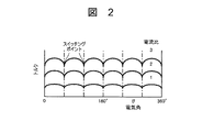
ブラシレスモータにおいては、1回転中の位置検出回数が限られるため、ロータの位置によるトルク差が生じることになり、周期的なトルクリップルを発生し、これにより回転むらが生じる。例えば、図1に示すロータ磁極数が2のブラシレスモータについて、ロータ位置により発生トルクに変動が生じることを説明する。図1において、ステータ磁界がθ=120°の位置にあるときに、ロータはθ=0°の位置からθ=60°の位置まで回転することになる。この回転区間において、ロータに発生するトルクはθの関数となりトルクの変動を生じる。このトルクリップルは図2に示すように、負荷電流により大きさが異なり、また1回転中のトルクリップルの回数は、ロータ磁極数が大きくなるにつれて増大するため、制御による方法をもってしても除去することは困難なように思われる。本発明は、このようなトルクリップルを低減し、回転むらの少ない永久磁石界磁形ブラシレスモータを提供することを目的としている。 In a brushless motor, since the number of times of position detection during one rotation is limited, a torque difference due to the position of the rotor is generated, and periodic torque ripple is generated, thereby causing uneven rotation. For example, it will be described that the generated torque varies depending on the rotor position in the brushless motor having two rotor magnetic poles shown in FIG. In FIG. 1, when the stator magnetic field is at the position of θ = 120 °, the rotor rotates from the position of θ = 0 ° to the position of θ = 60 °. In this rotation section, the torque generated in the rotor becomes a function of θ and causes torque fluctuation. As shown in FIG. 2, the magnitude of the torque ripple varies depending on the load current, and the number of torque ripples during one rotation increases as the number of rotor magnetic poles increases. It seems difficult. An object of the present invention is to provide a permanent magnet field-type brushless motor that reduces such torque ripple and has little rotation unevenness.
磁極数2P(Pは磁極対数)を有する永久磁石ロータと相数Mの電機子巻線を有するステータをもつブラシレスモータにおいて、例えば、3相120°通電方式の場合には、通常、ロータが1磁極ピッチ間隔(電気角360°)回転する間に、6回励磁が切り替わることになるので、磁極数2Pをもつ永久磁石ロータの場合には、1回転中にトルク変動は6P回生じることになる。 In a brushless motor having a permanent magnet rotor having the number of magnetic poles 2P (P is the number of magnetic pole pairs) and a stator having an armature winding of the number of phases M, for example, in the case of a three-phase 120 ° energization method, the rotor is usually 1 Since the excitation is switched six times during the rotation of the magnetic pole pitch interval (electrical angle 360 °), in the case of the permanent magnet rotor having the number of magnetic poles 2P, the torque fluctuation is generated 6P times during one rotation. .
本発明は、ロータの位置によってトルクが変動するこのトルクリップルに対して、磁極数2Pをもつ永久磁石ロータの一部を、磁極数12Pをもつ永久磁石ロータに置き換え、これとステータ間に発生するトルクで、磁極数2Pをもつ永久磁石ロータに発生するトルク変動を打ち消す、または磁極数2Pをもつ永久磁石ロータの一部を歯数が6P個のリラクタンス形ロータに置き換え、それに発生するリラクタンストルクによって、磁極数2Pをもつ永久磁石ロータに発生するトルク変動を打ち消すことによって、トルク変動を抑制しようとするものである。 The present invention replaces a part of the permanent magnet rotor having the number of magnetic poles 2P with a permanent magnet rotor having the number of magnetic poles 12P in response to the torque ripple in which the torque varies depending on the position of the rotor. Torque cancels torque fluctuations generated in a permanent magnet rotor with 2P magnetic poles, or replaces a part of a permanent magnet rotor with 2P magnetic poles with a reluctance type rotor with 6P teeth, and generates reluctance torque The torque fluctuation is to be suppressed by canceling the torque fluctuation generated in the permanent magnet rotor having the number of magnetic poles 2P.
このように、本発明による永久磁石界磁形ブラシレスモータは、ロータ磁極数2Pを有する永久磁石ロータと磁極数4PMを有する変動トルク相殺用永久磁石ロータを同軸上に設置したもので永久磁石ロータに発生するトルク変動を効果的に打ち消すことが出来る。 Thus, the permanent magnet field type brushless motor according to the present invention has a permanent magnet rotor having a rotor magnetic pole number 2P and a variable torque canceling permanent magnet rotor having a magnetic pole number 4PM installed on the same axis. The generated torque fluctuation can be effectively canceled out.
また、この磁極数4PMを有する変動トルク相殺用永久磁石ロータと同等の機能を持つ歯数2PMを有するリラクタンス形ロータを同軸上に設置しても同様にトルク変動を効果的に打ち消すことが出来る。 Further, even if a reluctance rotor having the number of teeth of 2 PM having the same function as the variable torque canceling permanent magnet rotor having the number of magnetic poles of 4 PM is installed on the same axis, the torque fluctuation can be effectively canceled in the same manner.
発明を実施するための最良の形態を図3乃至図14を用いて説明する。 The best mode for carrying out the invention that describes with reference to FIGS. 3 to 14.
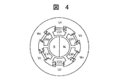
図3は永久磁石界磁ロータRm及びステータSを有するラジアルギャップ形の永久磁石界磁ブラシレスモータに本発明を適用した例を示す。ステータSの磁極U1, V1, W1, U2,V2, W3には図4に示すごとく3相の電機子巻線LU1,LV1,LW1,LU2,LV2,LW2が巻かれている。 FIG. 3 shows an example in which the present invention is applied to a radial gap type permanent magnet field brushless motor having a permanent magnet field rotor Rm and a stator S. As shown in FIG. 4, three-phase armature windings LU1, LV1, LW1, LU2, LV2, and LW2 are wound around the magnetic poles U1, V1, W1, U2, V2, and W3 of the stator S.
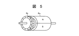
本発明のラジアルギャップ形の永久磁石界磁ブラシレスモータにおいては、磁極数2PをもつロータRmに、図5に示すように6×(2P)=12Pの磁極数をもつロータRsを同軸に設置する。 In the radial gap type permanent magnet field brushless motor of the present invention, a rotor Rs having a magnetic pole number of 2P and a rotor Rs having a magnetic pole number of 6 × (2P) = 12P as shown in FIG. .
図3に示す本発明のラジアルギャップ形永久磁石界磁ブラシレスモータにおける切断面X1−X1'の構造を、ロータRmについては図6(A)に、ステータSについては図7(A)に示す。また、当該永久磁石界磁ブラシレスモータの切断面X2−X2'の構造を、ロータRsについては図6(B)に、ステータSについては図7(B)に示す。 The structure of the cut surface X1-X1 ′ in the radial gap type permanent magnet field brushless motor of the present invention shown in FIG. 3 is shown in FIG. 6A for the rotor Rm and in FIG. 7A for the stator S. Further, the structure of the cut surface X2-X2 ′ of the permanent magnet field brushless motor is shown in FIG. 6B for the rotor Rs and in FIG. 7B for the stator S.
ロータRmとロータRsは図6(A)および(B)に示すように、ロータRmのN極の点線で示す中心位置(θ=0°)と、その中心位置(θ=0°)に最も近いロータRsのN極の中心位置とが互いに(15°/P)または(―15°/P)ずれて配置されている。 As shown in FIGS. 6A and 6B, the rotor Rm and the rotor Rs are located at the center position (θ = 0 °) indicated by the dotted line of the N pole of the rotor Rm and the center position (θ = 0 °). The positions of the N poles of the near rotor Rs are shifted from each other by (15 ° / P) or (−15 ° / P) .
また、ロータRsに対応するステータSの部分のステータ磁極には、図7(B)のように小歯をもたせている。これは、ロータRsの磁極数が大きくなるため、ステータ磁極を図7(A)のままにすると、ステータの1磁極中にロータRsの何組ものN−S両磁極が含まれることになり、ロータRsからの磁力が打ち消されることになるからである。図7(B)の小歯のピッチは、図8に示す如く、ロータRsの磁極ピッチ(電気角360°)と等しくしてある。 Further, the stator magnetic poles of the portion of the stator S corresponding to the rotor Rs have small teeth as shown in FIG. This is because the number of magnetic poles of the rotor Rs is large, and if the stator magnetic poles are left as shown in FIG. 7A, one magnetic pole of the stator includes several NS magnetic poles of the rotor Rs. This is because the magnetic force from the rotor Rs is canceled out. The pitch of the small teeth in FIG. 7B is equal to the magnetic pole pitch (electrical angle 360 °) of the rotor Rs as shown in FIG.
次に、永久磁石界磁ブラシレスモータに本発明を適用した別の実施例を示す。 Next, another embodiment in which the present invention is applied to a permanent magnet field brushless motor will be described.
ステータは上記実施例と同一であるが、磁極数2Pをもつロータの一部を、図9に示すように、磁極をもたずに6P個の歯をもつリラクタンス形のロータRs'に置き換える(元のロータ部分をRm、6P個の歯数をもつロータ部分をRs'で示す)。このとき、図3の切断面X2−X2'の構造は図10に示すようになる。 Although the stator is the same as that of the above embodiment, a part of the rotor having the number of magnetic poles 2P is replaced with a reluctance rotor Rs ′ having 6P teeth without magnetic poles as shown in FIG. The original rotor portion is indicated by Rm, and the rotor portion having 6P teeth is indicated by Rs ′). At this time, the structure of the cut surface X2-X2 ′ in FIG. 3 is as shown in FIG.
ロータRmとロータRs'は図11に示すように、近接するロータRmの磁極とロータRsの歯の中心位置とが互いに(15°/P)または( ― 15°/P)ずれて配置されている。 As shown in FIG. 11, the rotor Rm and the rotor Rs ′ are arranged such that the magnetic poles of the adjacent rotor Rm and the center position of the teeth of the rotor Rs are shifted from each other by (15 ° / P) or (−15 ° / P). Yes.
また、ロータRs’に対向するステータ磁極には図12のように小歯をもたせ、小歯間の間隔をロータRs'の歯ピッチ(電気角360°)と等しくしている。これは、前記ロータRs'の歯数が大きくなっても、一つのステータ磁極の中に複数個のロータRs'の歯が含まれないようにして、変動トルクの低減効果を高めるためである。 Further, the stator magnetic poles opposed to the rotor Rs ′ are provided with small teeth as shown in FIG. 12, and the interval between the small teeth is made equal to the tooth pitch of the rotor Rs ′ (electrical angle 360 °). This is because even if the number of teeth of the rotor Rs ′ is increased, the teeth of the plurality of rotors Rs ′ are not included in one stator magnetic pole, thereby increasing the effect of reducing the fluctuation torque.
つぎに、図1(ロータ磁極数2P=2の場合)を参照して、永久磁石界磁形ブラシレスモータのトルク変動を求め、本発明の永久磁石界磁ブラシレスモータにおいては、トルク変動が抑えられる理由を説明する。 Next, referring to FIG. 1 (when the number of rotor magnetic poles 2P = 2), the torque fluctuation of the permanent magnet field type brushless motor is obtained, and the torque fluctuation is suppressed in the permanent magnet field brushless motor of the present invention. Explain why.
図1に示す永久磁石界磁ブラシレスモータには、図13に示す回路により、電機子巻線LU1,LV1,LW1,LU2,LV2,LW2に3相電流が流れる。図において、Tr1, Tr2, Tr3, Tr4, Tr5, Tr6は3相電流を流すように制御するトランジスタ、D1, D2,D3,D4, D5, D6はダイオードを示す。 In the permanent magnet field brushless motor shown in FIG. 1, a three-phase current flows through the armature windings LU1, LV1, LW1, LU2, LV2, and LW2 by the circuit shown in FIG. In the figure, Tr1, Tr2, Tr3, Tr4, Tr5, and Tr6 are transistors that are controlled to flow a three-phase current, and D1, D2, D3, D4, D5, and D6 are diodes.
ステータの合成磁界がθ=120°の位置にあるとき、ロータRmはθ=0°からθ=60°まで移動することになる。このとき、ロータRmに発生するトルクは最大値を1とすると、
![]()
と表されるから、最大トルクは1、最小トルクは

となり、トルク変動が生じることになる。 そこで、ロータRsが発生する脈動トルクの振幅が
![]()
となるようにロータRsの界磁の強さを選んだとすると、ロータRsの発生トルクは
![]()
となる。
When the combined magnetic field of the stator is at the position of θ = 120 °, the rotor Rm moves from θ = 0 ° to θ = 60 °. At this time, when the maximum value of the torque generated in the rotor Rm is 1,
![]()
The maximum torque is 1 and the minimum torque is
Thus, torque fluctuation occurs. Therefore, the amplitude of the pulsating torque generated by the rotor Rs is
![]()
If the field strength of the rotor Rs is selected so that
![]()
It becomes.
このような関係が磁界の移動に伴って60°(電気角)周期で繰り返されることになるので、ロータRmの変動分トルク、ロータRsの発生トルク、および両者を合成した変動トルクは図14のようになり、変動トルクの振幅はロータRmが発生する変動分トルクの0.0401/0.134=0.3倍に減少することになる。 Since such a relationship is repeated at a period of 60 ° (electrical angle) with the movement of the magnetic field, the fluctuation torque of the rotor Rm, the generated torque of the rotor Rs, and the fluctuation torque obtained by combining both are shown in FIG. As a result, the amplitude of the fluctuation torque is reduced to 0.0401 / 0.134 = 0.3 times the fluctuation torque generated by the rotor Rm.
また、負荷変化により、電機子電流が変化してトルク変動の大きさが変化した場合でも、同時にロータRsによる発生トルクも電流とともに変化するため、この場合にもトルクリップルが最も抑制される条件は満たされることになる。 Even when the armature current changes due to load changes and the magnitude of torque fluctuation changes, the torque generated by the rotor Rs also changes with the current at the same time. Will be satisfied.
一般的には、磁極数2Pを有する永久磁石ロータと相数Mの電機子巻線を有するステータをもつブラシレスモータにおいては、該永久磁石ロータに磁極数4PMを有する変動トルク相殺用永久磁石ロータを同軸上に設置し、ロータRmとロータRsが、それぞれ近接する同極磁極の中心位置が互いに(90°/2PM)または(−90°/2PM)ずれて配置させることにより、図14の関係が得られ、両者の合成変動トルクの振幅はロータRmが発生する変動分トルクの0.0401/0.134=0.3倍に減少することになる。これにより、トルク変動の少ないブラシレスモータが得られることになる。
上記の(90°/2PM)は、M=3の場合、ロータRmとロータRsのずれは(15°/P)となり、図6および図11に示す場合の一般式であることがわかる。
In general, in a brushless motor having a permanent magnet rotor having 2P magnetic poles and a stator having M phase armature windings, a variable torque canceling permanent magnet rotor having 4PM magnetic poles is provided on the permanent magnet rotor. 14 are arranged on the same axis, and the rotor Rm and the rotor Rs are arranged so that the center positions of the adjacent homopolar poles are shifted from each other by (90 ° / 2PM) or (−90 ° / 2PM). As a result, the amplitude of the combined fluctuation torque of both is reduced to 0.0401 / 0.134 = 0.3 times the fluctuation torque generated by the rotor Rm. Thereby, a brushless motor with little torque fluctuation is obtained.
The above (90 ° / 2PM), when M = 3, indicates that the deviation between the rotor Rm and the rotor Rs is (15 ° / P), which is a general formula shown in FIGS.
実用的には、RmとRsのずれ角、およびRmとRs'とのずれ角を、Practically, the deviation angle between Rm and Rs and the deviation angle between Rm and Rs ′ are
(90±10)°/2PM(90 ± 10) ° / 2PM
程度に選べば、変動トルクの低減効果は十分期待される。If the degree is selected, the effect of reducing the fluctuation torque is sufficiently expected.
このように、本発明になる永久磁石界磁形ブラシレスモータは、トルク変動を効果的に打ち消すことが出来るので、回転むらが極めて少ないことを要求されるOA機器やFA機器に広く用いられる。 As described above, the permanent magnet field type brushless motor according to the present invention can effectively cancel the torque fluctuation, and thus is widely used in OA equipment and FA equipment that are required to have extremely little rotation unevenness.
R、Rs、Rs'…ロータ、S…ステータ、U1, V1, W1, U2, V2, W3…ステータSの磁
極、LU1,LV1,LW1,LU2,LV2,LW2…電機子巻線。
R, Rs, Rs' ... rotor, S ... stator, U1, V1, W1, U2, V2, W3 ... magnetic pole of stator S, LU1, LV1, LW1, LU2, LV2, LW2 ... armature winding.
Claims (2)
該永久磁石ロータに磁極数4PMを有する変動トルク相殺用永久磁石ロータを同軸上に設置し、
前記永久磁石ロータの特定の磁極の中心線と、該特定の磁極と同極である前記変動トルク相殺用永久磁石ロータの磁極であって前記中心線に対して最寄りの磁極の中心線によって形成されるずれ角が±(90±10)°/2PMであることを特徴とする永久磁石界磁ブラシレスモータ。 The permanent magnet field brushless motor consisting of stator with a permanent magnet rotor and M-phase armature winding having a number of magnetic poles 2P,
A variable torque canceling permanent magnet rotor having 4PM magnetic poles is installed on the permanent magnet rotor on the same axis,
A center line of a specific magnetic pole of the permanent magnet rotor and a magnetic pole of the variable torque canceling permanent magnet rotor that is the same polarity as the specific magnetic pole, and is formed by the center line of the magnetic pole nearest to the center line Permanent magnet field brushless motor characterized in that the slip angle is ± (90 ± 10) ° / 2PM.
該永久磁石ロータに歯数2PMを有するリラクタンス形ロータを同軸上に設置し、A reluctance rotor having 2PM teeth is installed on the same axis as the permanent magnet rotor,
前記永久磁石ロータの特定の磁極の中心線と、該リラクタンス形ロータの歯であって前記中心線に対して最寄りの歯の中心線によって形成されるずれ角が±(90±10)°/2PMであることを特徴とする永久磁石界磁ブラシレスモータ。The deviation angle formed by the centerline of the specific magnetic pole of the permanent magnet rotor and the toothline of the reluctance rotor that is closest to the centerline is ± (90 ± 10) ° / 2PM A permanent magnet field brushless motor characterized by
Priority Applications (1)
| Application Number | Priority Date | Filing Date | Title |
|---|---|---|---|
| JP2006041893A JP4604199B2 (en) | 2006-02-20 | 2006-02-20 | Permanent magnet field type brushless motor |
Applications Claiming Priority (1)
| Application Number | Priority Date | Filing Date | Title |
|---|---|---|---|
| JP2006041893A JP4604199B2 (en) | 2006-02-20 | 2006-02-20 | Permanent magnet field type brushless motor |
Publications (2)
| Publication Number | Publication Date |
|---|---|
| JP2007221955A JP2007221955A (en) | 2007-08-30 |
| JP4604199B2 true JP4604199B2 (en) | 2010-12-22 |
Family
ID=38498585
Family Applications (1)
| Application Number | Title | Priority Date | Filing Date |
|---|---|---|---|
| JP2006041893A Active JP4604199B2 (en) | 2006-02-20 | 2006-02-20 | Permanent magnet field type brushless motor |
Country Status (1)
| Country | Link |
|---|---|
| JP (1) | JP4604199B2 (en) |
Families Citing this family (5)
| Publication number | Priority date | Publication date | Assignee | Title |
|---|---|---|---|---|
| US7847457B2 (en) | 2007-05-09 | 2010-12-07 | Federal-Mogul World Wide, Inc | BLDC motor assembly |
| ITPN20110015A1 (en) * | 2011-03-11 | 2012-09-12 | Mate S A S Di Furlan Massimo & C | BRUSHLESS ELECTRIC MOTOR WITH PERMANENT MAGNET OF SINGLE-PHASE TYPE |
| US8766578B2 (en) | 2012-02-27 | 2014-07-01 | Canadian Space Agency | Method and apparatus for high velocity ripple suppression of brushless DC motors having limited drive/amplifier bandwidth |
| US20140300232A1 (en) * | 2013-03-08 | 2014-10-09 | Gerald K. Langreck | High acceleration rotary actuator |
| JP6841630B2 (en) | 2015-10-15 | 2021-03-10 | キヤノンメディカルシステムズ株式会社 | Specimen testing device |
Citations (2)
| Publication number | Priority date | Publication date | Assignee | Title |
|---|---|---|---|---|
| JPS63157652A (en) * | 1986-12-19 | 1988-06-30 | Canon Inc | Brushless motor |
| JPH04304134A (en) * | 1991-03-29 | 1992-10-27 | Mitsubishi Kasei Corp | Motor |
-
2006
- 2006-02-20 JP JP2006041893A patent/JP4604199B2/en active Active
Patent Citations (2)
| Publication number | Priority date | Publication date | Assignee | Title |
|---|---|---|---|---|
| JPS63157652A (en) * | 1986-12-19 | 1988-06-30 | Canon Inc | Brushless motor |
| JPH04304134A (en) * | 1991-03-29 | 1992-10-27 | Mitsubishi Kasei Corp | Motor |
Also Published As
| Publication number | Publication date |
|---|---|
| JP2007221955A (en) | 2007-08-30 |
Similar Documents
| Publication | Publication Date | Title |
|---|---|---|
| JP5322616B2 (en) | Permanent excitation type synchronous machine with shell magnet | |
| JP4519928B2 (en) | Hybrid excitation type synchronous machine | |
| JP4626382B2 (en) | Electric motor | |
| TWI414130B (en) | Single-phase brushless motor | |
| JP5421396B2 (en) | Electric motor having an iron core having primary teeth and secondary teeth | |
| JP6668844B2 (en) | Rotating electric machine | |
| JP2004274963A (en) | Permanent magnet motor for electric power steering device | |
| JP2006304546A (en) | Permanent magnet reluctance type rotary electric machine | |
| JP4604199B2 (en) | Permanent magnet field type brushless motor | |
| JP5188746B2 (en) | Brushless DC motor | |
| JP2008187830A (en) | Rotor for reluctance motor, and reluctance motor equipped with the same | |
| JP2011078202A (en) | Axial gap motor | |
| JP5609844B2 (en) | Electric motor | |
| KR20130067218A (en) | Motor | |
| JP4698062B2 (en) | Brushless DC motor | |
| JP5538984B2 (en) | Permanent magnet motor | |
| JP4718580B2 (en) | Permanent magnet type rotating electric machine and electric power steering device | |
| JP5419991B2 (en) | Permanent magnet synchronous motor | |
| JP2006352961A (en) | Pm motor | |
| JP5751147B2 (en) | Motor equipment | |
| WO2019202919A1 (en) | Cylindrical linear motor | |
| JP2000139047A (en) | Permanent-magnet motor | |
| JP5195450B2 (en) | Slotless motor | |
| JP2005278268A (en) | Permanent magnet type motor | |
| JP2009219183A (en) | Motor |
Legal Events
| Date | Code | Title | Description |
|---|---|---|---|
| A977 | Report on retrieval |
Free format text: JAPANESE INTERMEDIATE CODE: A971007 Effective date: 20090216 |
|
| A131 | Notification of reasons for refusal |
Free format text: JAPANESE INTERMEDIATE CODE: A131 Effective date: 20090224 |
|
| A521 | Request for written amendment filed |
Free format text: JAPANESE INTERMEDIATE CODE: A523 Effective date: 20090420 |
|
| A131 | Notification of reasons for refusal |
Free format text: JAPANESE INTERMEDIATE CODE: A131 Effective date: 20091027 |
|
| A521 | Request for written amendment filed |
Free format text: JAPANESE INTERMEDIATE CODE: A523 Effective date: 20091216 |
|
| TRDD | Decision of grant or rejection written | ||
| A01 | Written decision to grant a patent or to grant a registration (utility model) |
Free format text: JAPANESE INTERMEDIATE CODE: A01 Effective date: 20100907 |
|
| A01 | Written decision to grant a patent or to grant a registration (utility model) |
Free format text: JAPANESE INTERMEDIATE CODE: A01 |
|
| R150 | Certificate of patent or registration of utility model |
Free format text: JAPANESE INTERMEDIATE CODE: R150 |