JP4599228B2 - Wireless transceiver - Google Patents
Wireless transceiver Download PDFInfo
- Publication number
- JP4599228B2 JP4599228B2 JP2005156687A JP2005156687A JP4599228B2 JP 4599228 B2 JP4599228 B2 JP 4599228B2 JP 2005156687 A JP2005156687 A JP 2005156687A JP 2005156687 A JP2005156687 A JP 2005156687A JP 4599228 B2 JP4599228 B2 JP 4599228B2
- Authority
- JP
- Japan
- Prior art keywords
- transmission
- data
- priority
- received
- reception
- Prior art date
- Legal status (The legal status is an assumption and is not a legal conclusion. Google has not performed a legal analysis and makes no representation as to the accuracy of the status listed.)
- Expired - Fee Related
Links
- 230000005540 biological transmission Effects 0.000 claims description 224
- 238000000034 method Methods 0.000 claims description 59
- 238000012545 processing Methods 0.000 claims description 58
- 238000004891 communication Methods 0.000 claims description 29
- 101000741965 Homo sapiens Inactive tyrosine-protein kinase PRAG1 Proteins 0.000 claims description 16
- 102100038659 Inactive tyrosine-protein kinase PRAG1 Human genes 0.000 claims description 16
- 239000011159 matrix material Substances 0.000 claims description 5
- 238000010586 diagram Methods 0.000 description 13
- 239000000872 buffer Substances 0.000 description 7
- 238000003672 processing method Methods 0.000 description 5
- 238000005516 engineering process Methods 0.000 description 3
- 238000005259 measurement Methods 0.000 description 2
- 241000404883 Pisa Species 0.000 description 1
- 230000003139 buffering effect Effects 0.000 description 1
- 238000007796 conventional method Methods 0.000 description 1
- 238000012937 correction Methods 0.000 description 1
- 230000003247 decreasing effect Effects 0.000 description 1
- 230000006866 deterioration Effects 0.000 description 1
- 230000005236 sound signal Effects 0.000 description 1
Images


Classifications
-
- H—ELECTRICITY
- H04—ELECTRIC COMMUNICATION TECHNIQUE
- H04B—TRANSMISSION
- H04B7/00—Radio transmission systems, i.e. using radiation field
- H04B7/02—Diversity systems; Multi-antenna system, i.e. transmission or reception using multiple antennas
- H04B7/04—Diversity systems; Multi-antenna system, i.e. transmission or reception using multiple antennas using two or more spaced independent antennas
- H04B7/06—Diversity systems; Multi-antenna system, i.e. transmission or reception using multiple antennas using two or more spaced independent antennas at the transmitting station
- H04B7/0686—Hybrid systems, i.e. switching and simultaneous transmission
- H04B7/0689—Hybrid systems, i.e. switching and simultaneous transmission using different transmission schemes, at least one of them being a diversity transmission scheme
-
- H—ELECTRICITY
- H04—ELECTRIC COMMUNICATION TECHNIQUE
- H04B—TRANSMISSION
- H04B7/00—Radio transmission systems, i.e. using radiation field
- H04B7/02—Diversity systems; Multi-antenna system, i.e. transmission or reception using multiple antennas
- H04B7/04—Diversity systems; Multi-antenna system, i.e. transmission or reception using multiple antennas using two or more spaced independent antennas
- H04B7/0413—MIMO systems
-
- H—ELECTRICITY
- H04—ELECTRIC COMMUNICATION TECHNIQUE
- H04B—TRANSMISSION
- H04B7/00—Radio transmission systems, i.e. using radiation field
- H04B7/02—Diversity systems; Multi-antenna system, i.e. transmission or reception using multiple antennas
- H04B7/04—Diversity systems; Multi-antenna system, i.e. transmission or reception using multiple antennas using two or more spaced independent antennas
- H04B7/08—Diversity systems; Multi-antenna system, i.e. transmission or reception using multiple antennas using two or more spaced independent antennas at the receiving station
- H04B7/0868—Hybrid systems, i.e. switching and combining
- H04B7/0871—Hybrid systems, i.e. switching and combining using different reception schemes, at least one of them being a diversity reception scheme
-
- H—ELECTRICITY
- H04—ELECTRIC COMMUNICATION TECHNIQUE
- H04L—TRANSMISSION OF DIGITAL INFORMATION, e.g. TELEGRAPHIC COMMUNICATION
- H04L1/00—Arrangements for detecting or preventing errors in the information received
- H04L1/0001—Systems modifying transmission characteristics according to link quality, e.g. power backoff
-
- H—ELECTRICITY
- H04—ELECTRIC COMMUNICATION TECHNIQUE
- H04L—TRANSMISSION OF DIGITAL INFORMATION, e.g. TELEGRAPHIC COMMUNICATION
- H04L1/00—Arrangements for detecting or preventing errors in the information received
- H04L1/02—Arrangements for detecting or preventing errors in the information received by diversity reception
- H04L1/06—Arrangements for detecting or preventing errors in the information received by diversity reception using space diversity
- H04L1/0618—Space-time coding
- H04L1/0625—Transmitter arrangements
-
- H—ELECTRICITY
- H04—ELECTRIC COMMUNICATION TECHNIQUE
- H04W—WIRELESS COMMUNICATION NETWORKS
- H04W88/00—Devices specially adapted for wireless communication networks, e.g. terminals, base stations or access point devices
- H04W88/02—Terminal devices
- H04W88/06—Terminal devices adapted for operation in multiple networks or having at least two operational modes, e.g. multi-mode terminals
-
- H—ELECTRICITY
- H04—ELECTRIC COMMUNICATION TECHNIQUE
- H04L—TRANSMISSION OF DIGITAL INFORMATION, e.g. TELEGRAPHIC COMMUNICATION
- H04L1/00—Arrangements for detecting or preventing errors in the information received
- H04L1/0001—Systems modifying transmission characteristics according to link quality, e.g. power backoff
- H04L1/0002—Systems modifying transmission characteristics according to link quality, e.g. power backoff by adapting the transmission rate
- H04L1/0003—Systems modifying transmission characteristics according to link quality, e.g. power backoff by adapting the transmission rate by switching between different modulation schemes
-
- H—ELECTRICITY
- H04—ELECTRIC COMMUNICATION TECHNIQUE
- H04L—TRANSMISSION OF DIGITAL INFORMATION, e.g. TELEGRAPHIC COMMUNICATION
- H04L1/00—Arrangements for detecting or preventing errors in the information received
- H04L1/0001—Systems modifying transmission characteristics according to link quality, e.g. power backoff
- H04L1/0009—Systems modifying transmission characteristics according to link quality, e.g. power backoff by adapting the channel coding
Description
本発明は、送信装置と受信装置のそれぞれにおいて少なくとも2つ以上のアンテナを用いるMIMO無線通信システムの無線送受信機に係り、特に、映像データや音データなどの伝送をおこなうなど、伝送品質が問われる利用環境に好適な無線送受信機に関する。 The present invention relates to a wireless transceiver of a MIMO wireless communication system using at least two or more antennas in each of a transmission device and a reception device, and in particular, transmission quality is questioned, such as transmission of video data, sound data, and the like. The present invention relates to a wireless transceiver suitable for a use environment.
従来の無線通信システムとしてIEEE802.11において規格化された無線LANシステムが存在する(非特許文献1、2参照)。
There is a wireless LAN system standardized in IEEE 802.11 as a conventional wireless communication system (see Non-Patent
この無線LAN技術においては、データの優先度に応じて伝送制御をおこなう技術が知られている。以下の特許文献1には、パケットの優先度に応じて、符号化率と変調方式を制御する技術が開示されている。また、以下の特許文献2には、特に、そのようにして映像データを転送する技術が開示されている。具体的な優先度のTGe(IEEE802.11 Task Group e)の規格については、例えば、以下の非特許文献3に解説がある。
In this wireless LAN technology, a technology for performing transmission control according to the priority of data is known.
一方、無線LAN技術において、MIMO(Multiple-Input Multiple Output)伝送方式が注目をあびている。 MIMO伝送は、無線送受信機において、複数のアンテナでデータの送信/受信をおこない、データの合成や復号を行うことで、従来の無線LANの通信速度と比べて高速化するとともに、マルチパス(反射波)環境下でも安定した通信をおこなえるようにするというのが特徴である。 On the other hand, in the wireless LAN technology, a MIMO (Multiple-Input Multiple Output) transmission method has attracted attention. In MIMO transmission / reception, data is transmitted / received by a plurality of antennas in a wireless transmitter / receiver, and data is synthesized and decoded, so that the communication speed is increased compared to the conventional wireless LAN communication speed and multipath (reflection) is performed. The feature is to enable stable communication even in a wave environment.
MIMO伝送に関しては、以下の非特許文献4に示されるように、元の送信データを複数の送信ストリームに分配し、複数のアンテナから同時に送信する方法(SDM(Space Division Multiplexing)や、非特許文献5に示されるように通常の送受信にアンテナを1つずつ用いる場合とデータレートは同じであるが、送受信ダイバシティにより従来より確実に無線伝送する方法(STBC(Space Time Block Coding)が知られている。SDMによるMIMO信号処理は、通常の送受信にアンテナを一つずつ用いる無線システムに対して送信アンテナ数に比例してデータレートを高くすることが可能となり、 STBCによる信号処理はデータレートは高くならないが、アンテナ数の増加に伴い、より確実な無線伝送を実現するものである。
As for MIMO transmission, as shown in
なお、以下の特許文献3においては、MIMOの規格による伝送方法と他の規格による伝送方法を組み合わせたハイブリッドな無線通信システムが開示されている。
Note that
先ず、課題を説明するために、図2、および図3を用いて従来技術に係る無線LANシステムの無線送受信機の構成について説明する。 First, in order to explain the problem, the configuration of the wireless transceiver of the wireless LAN system according to the prior art will be described using FIG. 2 and FIG.
図2は、従来技術に係る無線LANシステムの無線送受信機の構成図である。 FIG. 2 is a configuration diagram of a wireless transceiver of a wireless LAN system according to the prior art.
図3は、送信データの優先制御において、送信データが優先制御のキューに格納されることを示した図である。 FIG. 3 is a diagram illustrating that transmission data is stored in a priority control queue in transmission data priority control.
従来技術に係る無線LANシステム1は、無線送受信機2a,2bより構成されている。送信データ3aは、優先制御部10aにバッファリングされその優先度が高いデータほど先に送信されやすいよう制御される。優先制御部10aにバッファリングされた送信データは、送信時に符号化処理部11aにより無線伝送時の誤り耐性を高めるため符号化される。続いて符合化された送信データは、MIMO信号処理部12aにより送信ストリームに分割される。アンテナ18aが、図2のように二つからなるときには、MIMO信号処理部12aは、送信データから二つの送信ストリームを生成する。この生成手順は後述する。
The
ここで、図3を用いて、優先制御部10の動作について説明する。優先制御部10は、上記非特許文献3に記載されているIEEE802.11 Task Group e(TGe)にて規格化中の方式を用いる。送信データ3aは、アプリケーションにより、予め優先度付きで優先制御部10に入力される。優先制御部10では、この送信データを四つの優先度に分類する(101)。音声のようにレイテンシが重視されるデータは最も優先度が高く、ここでは、AC_VOとして分類される(102)。また、映像信号のように多少のバッファリングが許されるデータは2番目に優先度が高いAC_VDに分類される(103)。さらに、通常のデータは3番目に優先度の高いデータとしてAC_BEとして分類される(104)。そして、バックグランドデータのように緊急性の低いデータは優先度が最も低いAC_BGに分類される(105)。図3に示すように四つの分類毎にデータを保存するバッファ102〜105が存在する。それぞれのバッファは、先に入力されたデータから先に出て行くFIFO(First-In First-Out)構造となっている。各バッファのいずれか一つにデータが存在する場合、実際に送信するデータを決定する手順として、優先度の高いデータほど確率的に送信しやすくすることで、優先度の高いデータを優先的に送信することが可能となる。
Here, the operation of the
MIMOの伝送方式に関しては、上記のように非特許文献4に示されたSDMのようにデータレートを高くする仕方と、非特許文献5に示されたSTBCがある。
As for the MIMO transmission method, there are a method of increasing the data rate as in SDM shown in
MIMO信号処理12aでは、上記のSDM,STBCのいずれかを用いて二つの送信ストリームを生成する。それぞれの送信ストリームは、変調部13aで適当な変調方式で変調され、送信用RF(Radio Frequency)部14aで高周波信号にアップコンバートされ、送受信切り替えスイッチ17aを介して、アンテナ18aから送信される。受信側では、アンテナ18bで受信した信号は、受信用RF部20bにおいて増幅され、ダウンコンバートされて復調機21bに入力される。ここで、送信側が用いた変調方式や符号化率といった情報を受信側が得るためには送信データと共に用いた変調方式や符号化率を通知する仕組みが必要である。通常、これらの情報は、送信データの送信時にそのヘッダ情報として伝送される。これらのフレーム構造の詳細は、上記の非特許文献1及び非特許文献2に開示される方法を用いることで実現できる。復調部21bで復調された複数の信号はMIMO信号処理部22bに入力され、一つのデータ列に変換され、復号部23bに入力される。復号部23bで誤り訂正されたデータは、再送制御24bで受信フレームが正しく受信できたかをチェックされ、正しく受信したと判断された場合には、ACK(Acknowledgement)フレームを、誤りがあると判断した場合には、NACK(Not Acknowledgement)フレームを、所定の時間以内または所定のタイミングで送信する。ここでは、ACKフレームとNACKフレームの両者をまとめて応答フレームと呼ぶことにする。これらの応答フレームは、再送制御部で構成され、符号化11bに入力され、前述した送受信機2aの送信処理と同様に処理され、送信される。送受信機2aは、送受信機2bから送信された応答フレームを受信することで送信データが正しく伝送できたか否かを知ることができる。送受信機2aは、ACKフレームを受信した場合、送信データが送信機2bに正しく伝送できたと判断し、優先制御内にバッファリングされていた送信データを消去する。また、NACKフレームを受信した場合、あるいは所定の時間以内または所定のタイミングで応答フレームを受信しなかった場合には、送信データを送受信機2bに正しく伝送できていないと判断し、先に送信したデータを再び送信(再送)する。再送を繰り返すことで最終的に送信データを送信先に伝送することができる。ここで、再送が発生するということは、先の送信データ送信時の伝送路の条件が悪かった可能性が高いと考えられ、再送時には変調方式、符号化率、MIMO信号処理方式を変更し、前回送信時と比較してより確かに送信できる方式を選択するよう動作する。
In the
例えば、MIMOにおいて、データ送信時のビットレートと、変調方式および符号化処理部率の組み合わせは、以下の表1の如くである。 For example, in MIMO, a combination of a bit rate at the time of data transmission, a modulation method, and a coding processing unit rate is as shown in Table 1 below.

さらに、MIMO信号処理方式についても同様に伝送誤りが多いときには上記STBCを用い、送受信機間の距離が近い等の伝送路の状況が良く、データの誤りが少ない場合にはSDMを用いることで、効率良くデータを伝送することができる。 Furthermore, similarly for the MIMO signal processing method, the STBC is used when there are many transmission errors, the transmission path conditions such as the distance between the transceivers are close, and the SDM is used when there are few data errors. Data can be transmitted efficiently.
従来、符号化、MIMO信号処理、変復調を制御する物理層は伝送の条件の悪化に対して、NACKフレームの受信やACK/NACKフレームそのものが受信できない等により、そのパラメータを変化させ、データレートを低くする等してデータの送信を試みていた。このため、例えば、音声信号や映像ストリーミングのようにレイテンシを要求するデータとそれ以外のデータとの区別なく同じ動作をおこなっており、効率が悪いという問題がある。 Conventionally, the physical layer that controls encoding, MIMO signal processing, and modulation / demodulation changes the parameters by changing the parameters such as the reception of a NACK frame or the reception of an ACK / NACK frame itself in response to the deterioration of transmission conditions. Attempted to send data by lowering it. For this reason, for example, the same operation is performed without distinction between data requiring latency and other data such as an audio signal or video streaming, and there is a problem that efficiency is poor.
上記特許文献1および特許文献2には、データ優先度に基づいて、通信をおこなう無線送受信機は、開示されているものの、MIMOの無線送受信機に応用される例は開示されていない。また、上記特許文献3には、MIMOの送受信をおこなえる無線通信システムにおいて、データセグメントのタグが示すデータの重要度に応じてパスを切り替える構成が開示されているが、複数アンテナを使用するMIMOの送受信モードと、単一のアンテナを使用するモードを切り替えるのみであり、上記MIMOの無線送受信機で用いられる伝送方式であるSDMと、STBCを考慮したものではない。
Although
本発明は、上記問題点を解決するためになされたもので、その目的は、MIMOの無線送受信機により構成された無線通信システムにおいて、送信データの優先度に応じて符号化、MIMO信号処理、変調方式の制御をおこなうようにする。すなわち、優先度の高いデータは、確実に伝送をおこなえるようにし、複数の種類データを送信するにあたりトータルのスループットを向上させることのできる無線通信システムを提供することにある。 The present invention has been made to solve the above-described problems, and its purpose is to perform encoding, MIMO signal processing, and transmission according to the priority of transmission data in a wireless communication system configured with a MIMO wireless transceiver. Control the modulation method. That is, it is an object of the present invention to provide a wireless communication system capable of reliably transmitting high priority data and improving the total throughput when transmitting a plurality of types of data.
上記課題を解決するために、本発明のMIMOにより伝送をおこなう無線送受信機において、送信データの優先度を判定する優先制御部と送信モードテーブルを設けて、送信時に送信データの優先度と送信先の送信モードに基づき、MIMOの伝送方式であるSDM、STBCで送信するか、符号化率、変調方式を制御する。 In order to solve the above-described problem, in the wireless transceiver that performs transmission by MIMO according to the present invention, a priority control unit for determining the priority of transmission data and a transmission mode table are provided, and the priority of transmission data and the destination of transmission are provided at the time of transmission. On the basis of the transmission mode, transmission is performed by SDM and STBC, which are MIMO transmission schemes, or the coding rate and modulation scheme are controlled.
一般的な法則として、優先度が高く、誤りを少なくしたいときには、伝送方法としてSTBCを用い、変調方式をBPSKにし、符号化率を高くする。優先度が低いときには、その逆であり、伝送方法としてSDMを用い、変調方式を64QAMにし、符号化率を低くする。通信路の状態は、送受信機間でやりとりされるACKフレーム、 NACKフレームの受信の有無や信号強度、また、伝送行列の固有値により判断することができる。 As a general rule, when priority is high and it is desired to reduce errors, STBC is used as the transmission method, the modulation method is set to BPSK, and the coding rate is increased. When the priority is low, the reverse is true, using SDM as the transmission method, the modulation scheme is 64QAM, and the coding rate is lowered. The state of the communication path can be determined by the presence / absence or signal strength of the ACK frame and NACK frame exchanged between the transceivers and the eigenvalue of the transmission matrix.
このように本発明に係る無線送受信機によれば、より柔軟にMIMO信号処理方法を選択することが可能となり、優先度の高いデータを更に効率よく無線伝送することができる。 As described above, according to the radio transceiver according to the present invention, the MIMO signal processing method can be selected more flexibly, and data with high priority can be more efficiently transmitted by radio.
このように、本発明のMIMOの無線送受信機は、送信データの優先度に応じて符号化、MIMO信号処理、変調方式を選択するようにしているため、優先度と関係なく伝送路の状況のみに従い符号化、MIMO信号処理、変調方式を選択していた従来方式と比較して、特に、優先度の高い送信データの伝送にかかる再送回数の低減、伝送遅延時間の短縮、スループットの向上を図ることができる。また、送信データに対する応答フレームの受信電力強度やMIMO信号処理で求めた伝送行列の固有値から伝送路の状況を知る方法や応答フレーム中に受信側が送信データを受信したときの伝送路に関する情報を加えて送信し、この情報を送信側が取得することで伝送路の状況を知る方法を用いて得られた伝送路情報と、送信データの優先度から送信モードテーブルに基づき決定される符号化、MIMO信号処理、変調方式を使用することで、より柔軟にデータ送信が可能となり、さらなる再送回数の低減、伝送遅延時間の短縮、スループットの向上を図ることができる。 As described above, the MIMO radio transceiver according to the present invention selects the encoding, MIMO signal processing, and modulation method according to the priority of the transmission data, so only the state of the transmission path is determined regardless of the priority. Compared with the conventional method in which encoding, MIMO signal processing, and modulation method are selected according to the above, particularly, the number of retransmissions for transmission of transmission data with high priority is reduced, the transmission delay time is shortened, and the throughput is improved. be able to. Also, a method for knowing the state of the transmission path from the received power intensity of the response frame for the transmission data and the eigenvalue of the transmission matrix obtained by MIMO signal processing, and information on the transmission path when the receiving side receives the transmission data during the response frame are added. Transmission information obtained by using a method of knowing the state of the transmission path by acquiring this information on the transmission side, and encoding determined based on the transmission mode table from the priority of the transmission data, MIMO signal By using the processing and modulation methods, data transmission can be performed more flexibly, and the number of retransmissions can be further reduced, the transmission delay time can be shortened, and the throughput can be improved.
本発明によれば、MIMOの無線送受信機により構成された無線通信システムにおいて、送信データの優先度に応じて符号化、MIMO信号処理、変調方式の制御をおこなうような無線通信システムを提供することができる。 According to the present invention, there is provided a wireless communication system configured to perform encoding, MIMO signal processing, and modulation scheme control in accordance with the priority of transmission data in a wireless communication system configured with a MIMO wireless transceiver. Can do.
以下、本発明に係る各実施例を、図1、図4ないし図12を用いて説明する。 Embodiments according to the present invention will be described below with reference to FIGS. 1 and 4 to 12.
以下、本発明に係る第一の実施例を、図1、図4ないし図9を用いて説明する。 Hereinafter, a first embodiment according to the present invention will be described with reference to FIGS. 1 and 4 to 9.
先ず、図1を用いて本発明の第一の実施例に係る送受信機の構成を説明する。 First, the configuration of the transceiver according to the first embodiment of the present invention will be described with reference to FIG.
図1は、本発明の第一の実施例に係る送受信機2の構成図である。
FIG. 1 is a block diagram of a
本発明の第一の実施例に係るMIMOの無線送受信機においては、送信データ3aは、優先制御部10aにバッファリングされ、その優先度が高いデータほど先に送信されやすいよう制御される。
In the MIMO radio transceiver according to the first embodiment of the present invention, the transmission data 3a is buffered in the
本実施例に示すMIMO無線通信システム1は、無線送受信機2aと無線送受信機2bが複数のアンテナにより無線でデータ通信をおこなうものである。
The MIMO
無線送受信機2aは、送信側である優先制御部10a、符号化処理部11a、MIMO信号処理部12a、変調部13a、送信RF部14aと、送信モードテーブル処理部15a、符号/MIMO/変調制御部16aよりなる。
The
送信データ3aは、優先制御部10aに入力され、上記背景技術で説明したように、データの優先度にしたがってバッファリングされる。そして、送信データは、符号化処理部11aにより、誤り訂正のため符号化処理され、MIMO信号処理部12aに入力される。
The transmission data 3a is input to the
MIMO信号処理部12aでは、上記背景技術で説明したように、SDM、STBC伝送方式のいずれかを用いて二つの送信ストリームを生成する。そして、変調部13aで適当な変調方式で変調され、送信用RF部14aで高周波信号にアップコンバートされ、送受信切り替えスイッチ17aを介して、アンテナ18aから送信される
ここまでの動作の記述は、上記背景技術に示した通りであるが、ここでは優先制御10aで制御された送信データの送信時には、その送信データがどの優先度に分類されているかを示す情報と送信相手を示す物理的な識別子であるMACアドレスを送信モードテーブル処理部15に伝送する機能を有する。
The MIMO
送信モードテーブル処理部15は、送信モードテーブルに従って、送信先のMACアドレスから送信モードを検索する。送信モードテーブル処理部15は、後に説明するように、MACアドレスと送信モードが対応付けられている。
The transmission mode
そして、符号/MIMO/変調制御部16aは、送信モードテーブル処理部15により検索された送信モードと、その送信データの優先度に基づいて、各々の符号化、MIMO信号処理、変調方式を定めて、それを各々上記の符号化処理部11a、MIMO信号処理部12a、変調部13aに伝える。
Then, the code / MIMO /
送信データは、伝えられた情報に基づき、各部において、符号化処理、MIMO信号処理、変調がおこなわれて、送信RF部14aで高周波信号にアップコンバートされ、アンテナ18aから送信される。
The transmission data is subjected to encoding processing, MIMO signal processing, and modulation in each unit based on the transmitted information, up-converted to a high-frequency signal by the
受信側の無線送受信機2bは背景技術に記載の通りの手順で応答フレームを送信する。
The
無線送信機2aでは受信した応答フレームを、前述した背景技術と同様の処理をおこなうことで再送制御をおこなう。
The
次に、図4および図5を用いて送信モードテーブルの構造と、送信モードとMIMO方式、符号化、偏重方式の決定ルールの一例について説明する。 Next, the structure of the transmission mode table and an example of rules for determining the transmission mode, the MIMO scheme, the encoding, and the biasing scheme will be described with reference to FIGS.
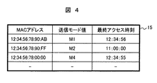
図4は、送信モードテーブルの一例を示す図である。 FIG. 4 is a diagram illustrating an example of a transmission mode table.
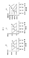
図5は、符号化、MIMO信号処理、変調方式を決定するルールを示したグラフである。 FIG. 5 is a graph showing rules for determining encoding, MIMO signal processing, and modulation scheme.
送信モードテーブル164は、通信相手を一意に特定する識別子と、伝送路の状態を示す送信モードと、通信相手からの信号を受信した時刻を保存する。ここでは通信相手を一意に特定する識別子としてMACアドレスを用いる。伝送路の状態は通信相手ごとに異なるため通信相手ごとに伝送路の状態を保存する必要がある。ここでは伝送路の状態は、M1〜M4の4段階とした。M1が最も通信路の状態がよく、M4が最も通信路の状態が悪いものと規定する。さらに、きめ細かく伝送路の状態を規定してもよい。また、伝送路の状態は時間によって変動するため時刻情報と共に保存することで、その伝送路情報の有効性を知ることができる。 The transmission mode table 164 stores an identifier that uniquely identifies a communication partner, a transmission mode that indicates the state of the transmission path, and a time at which a signal from the communication partner is received. Here, a MAC address is used as an identifier for uniquely identifying a communication partner. Since the state of the transmission path is different for each communication partner, it is necessary to save the state of the transmission path for each communication partner. Here, the state of the transmission path is set in four stages M1 to M4. It is defined that M1 has the best communication channel state and M4 has the worst communication channel state. Further, the state of the transmission line may be defined in detail. Further, since the state of the transmission path varies depending on time, it is possible to know the validity of the transmission path information by storing it together with the time information.
そして、送信データの優先度と、求められた送信モードに基づいて、一定のルールにより、符号化、MIMO信号処理、変調方式を決定する。 Then, based on the priority of the transmission data and the determined transmission mode, encoding, MIMO signal processing, and modulation scheme are determined according to certain rules.
送信データの優先度は背景技術の欄に前述した四つのものに分類されているものとする。一方、伝送路の状態を示す送信モードは、M1〜M4の四つのいずれかの一つである。 It is assumed that the priorities of transmission data are classified into the four items described above in the background art column. On the other hand, the transmission mode indicating the state of the transmission path is one of four of M1 to M4.
MIMO信号処理の決定は、例えば、図5のグラフ151に従っておこなうことができる。 The determination of the MIMO signal processing can be performed, for example, according to the graph 151 in FIG.
例えば、優先度がAC_VD(最高)である場合には、送信モードがM1(通信路:良)であれば第1のMIMO信号処理方法を用い、送信モードがM2〜M4であれば、第2のMIMO信号処理を用いる(161)。優先度が、AC_VOの場合には、送信モードに関わらず第2のMIMO信号処理方法を用いる。同様に符号化方式と変調方式の選択(図5のグラフ162、163)も、優先度と送信モードから一意に決定することができる。これらの優先度と、各々のMIMO信号処理、符号化、変調方式の対応を示すと、以下の表2に示すようになる。
For example, when the priority is AC_VD (highest), the first MIMO signal processing method is used if the transmission mode is M1 (communication path: good), and the second is used if the transmission mode is M2 to M4. The MIMO signal processing is used (161). When the priority is AC_VO, the second MIMO signal processing method is used regardless of the transmission mode. Similarly, the selection of the encoding method and the modulation method (
先ず、図6を用いて送受信の概要を示す動作手順について説明する。 First, an operation procedure showing an outline of transmission / reception will be described with reference to FIG.
図6は、本発明の第一の実施例の送受信の概要を示すフローチャートである。 FIG. 6 is a flowchart showing an outline of transmission and reception in the first embodiment of the present invention.
無線送受信機は動作を開始(S0)した後、受信信号の有無(S1)と送信データの有無(S2)を調べ続ける。受信信号がある場合には、受信処理(S10)をおこない、再び、受信信号の有無を確認する(S1)動作に移行する。送信データが存在する場合には、送信処理(S20)をおこない、送信後に応答フレーム受信(S11)に移行する。 After starting the operation (S0), the wireless transceiver continues to check the presence / absence of a received signal (S1) and the presence / absence of transmission data (S2). If there is a received signal, the receiving process (S10) is performed, and the operation again moves to the operation of confirming the presence or absence of the received signal (S1). If transmission data exists, transmission processing (S20) is performed, and the process proceeds to response frame reception (S11) after transmission.
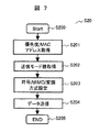
次に、図7を用いて送信処理(S20)の詳細な手順について説明する。 Next, a detailed procedure of the transmission process (S20) will be described with reference to FIG.
図7は、本発明の第一の実施例の送信時の詳細な動作を示すフローチャートである。 FIG. 7 is a flowchart showing a detailed operation during transmission according to the first embodiment of this invention.
送信処理(S20)が開始(S200)されると、送信データの優先度とMACアドレスを優先制御部10から受け取る(S201)。これらの値を基に、上記に説明したように、送信モードテーブル処理部15が送信モードテーブルの値に従って、送信先のMACアドレスに対応する送信モードを選択する(S202)。ここで得られた送信モード値を基に、上記の例で説明したように、符号/MIMO信号処理/変調制御部16は、符号化率、MIMO信号処方式、変調方式を決定し、その情報に基づいて、符号化処理部11、MIMO信号処理部12、変調部13は各々の処理をおこない(S203)、最終的にアンテナ18からデータが送信される(S204)。
When the transmission process (S20) is started (S200), the priority and MAC address of the transmission data are received from the priority control unit 10 (S201). Based on these values, as described above, the transmission mode
次に、図8を用いて受信処理(S10)の詳細な手順について説明する。 Next, a detailed procedure of the reception process (S10) will be described with reference to FIG.
図8は、本発明の第一の実施例の受信時の詳細な動作を示すフローチャートである。 FIG. 8 is a flowchart showing a detailed operation at the time of reception in the first embodiment of the present invention.
受信処理(S10)が開始されると(S100)、先ず、自局宛か否かを判断する(S101)。自局宛でなければ、受信処理を終了する(S105)。自局宛の場合には、受信フレームのエラーの有無をチェックする(S102)。受信フレームにエラーがない場合は、正しく受信できたことを通知するACKフレームを送信し(S103)、受信処理を終了する(S105)。受信フレームにエラーがある場合は、正しく受信できなかったことを通知するNACKフレームを送信し(S104)、受信処理を終了する(S105)。 When the reception process (S10) is started (S100), it is first determined whether or not it is addressed to the own station (S101). If not addressed to the own station, the reception process is terminated (S105). If it is addressed to the own station, it is checked whether there is an error in the received frame (S102). If there is no error in the received frame, an ACK frame notifying that the reception was successful is transmitted (S103), and the reception process is terminated (S105). If there is an error in the received frame, a NACK frame notifying that the reception was not successful is transmitted (S104), and the reception process is terminated (S105).
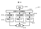
次に、図9を用いて応答フレーム受信時(S11)の詳細な手順について説明する。 Next, a detailed procedure when the response frame is received (S11) will be described with reference to FIG.
図9は、本発明の第一の実施例の応答フレーム受信時の詳細な動作を示すフローチャートである。 FIG. 9 is a flowchart showing a detailed operation when a response frame is received according to the first embodiment of the present invention.
応答フレーム受信(S11)が、開始されると(S110)、応答フレーム受信待ち状態(S111)となる。所定の時間または予め決められたタイミングでACKフレームが受信された場合(S112)には、伝送路の状態が良いということで送信モード値を1つ上げる(S115)。例えば、送信モードがM2であればM1とする。所定の時間または予め決められたタイミングで、NACKフレームが受信された場合(S113)には、伝送路の状態が悪いということで送信モード値を1つ下げる(S116)。例えば、送信モードがM2であればM3とする。所定の時間または予め決められたタイミングで応答フレームが受信されなかった場合(S114)は伝送路の状態が非常に悪いということで送信モード値を2つ下げる(S117)。例えば、送信モードがM2であればM4とする。 When response frame reception (S11) is started (S110), a response frame reception waiting state (S111) is entered. When an ACK frame is received at a predetermined time or at a predetermined timing (S112), the transmission mode value is increased by 1 because the transmission path state is good (S115). For example, if the transmission mode is M2, M1 is set. When a NACK frame is received at a predetermined time or at a predetermined timing (S113), the transmission mode value is decreased by 1 because the transmission path state is bad (S116). For example, if the transmission mode is M2, M3 is set. When a response frame is not received at a predetermined time or at a predetermined timing (S114), the transmission mode value is lowered by two because the state of the transmission path is very bad (S117). For example, if the transmission mode is M2, M4 is set.
以上に示した動作により、送信データの優先度に応じて符号化、MIMO信号処理、変調方式の制御を行う無線通信システムを構成する無線送受信機を実現することができる。 With the operation described above, it is possible to realize a radio transceiver that constitutes a radio communication system that performs encoding, MIMO signal processing, and modulation scheme control according to the priority of transmission data.
本実施例では再送制御部24からの応答フレーム受信の有無から送信制御テーブルの送信モード値を変更し、これと優先度に基づいて符号化、MIMO信号処理方式、変調方式を決定するとしたが、最も優先度の高い送信データを送信する場合にはデータレートを犠牲にして最も確実に伝送が可能となる符号化率、MIMO信号処理、変調方式を選択するよう予め固定的に決めておいても良い。
In this embodiment, the transmission mode value of the transmission control table is changed based on whether or not a response frame is received from the
以下、本発明に係る第二の実施例を、図10および図11を用いて説明する。 A second embodiment according to the present invention will be described below with reference to FIGS.
図10は、本発明に係る第二の実施例に係る送受信機の構成図である。 FIG. 10 is a block diagram of a transceiver according to the second embodiment of the present invention.
図11は、受信RF部における受信信号強度測定をおこなうための構成図である。 FIG. 11 is a configuration diagram for performing reception signal strength measurement in the reception RF unit.
第一の実施例では、応答フレームによって伝送路の品質を推定し、これに基づいて送信モードテーブルを更新した。 In the first embodiment, the quality of the transmission path is estimated from the response frame, and the transmission mode table is updated based on the estimated quality.
本実施例は、これに対して応答フレーム受信時の受信信号強度を元に伝送路の品質を推定し、これに基づいて送信モードテーブルを更新する方法である。 In this embodiment, the quality of the transmission path is estimated based on the received signal strength when the response frame is received, and the transmission mode table is updated based on this.
図10に示されるように、本実施例では、受信RF部20において受信信号の強度を測定し、これを送信モードテーブルに通知することで伝送路の品質を知ることができる。受信信号強度が大きいほど、伝送路の品質が良いと判断できるためである。
As shown in FIG. 10, in this embodiment, the
受信RF部における受信信号強度を測定するための具体的な方法は、図11に示されるように、アンテナ18から受信した信号を、低雑音アンプ201により増幅して、方向性結合器202により信号の一部を受信電力強度検出器203に入力することにより、信号強度を測定することができる。
As shown in FIG. 11, a specific method for measuring the received signal strength in the reception RF unit is that the signal received from the
以下、本発明に係る第三の実施例を、図12を用いて説明する。 Hereinafter, a third embodiment according to the present invention will be described with reference to FIG.
図12は、本発明に係る第三の実施例に係る送受信機の構成図である。 FIG. 12 is a block diagram of a transceiver according to the third embodiment of the present invention.
本実施例では、伝送路の品質を推定し、これに基づいて送信モードテーブルを更新するために受信MIMO信号処理部からのデータを用いる。 In this embodiment, the quality of the transmission path is estimated, and data from the received MIMO signal processing unit is used to update the transmission mode table based on the estimated quality.
受信MIMO信号処理部では、MIMO信号の受信のために伝送行列を求める。よって応答フレームの受信時にこの伝送行列の固有値を求め、その固有値の大小により伝送路の品質を推定することができる。固有値の合計が大きいほど伝送路の状態が良く、逆に固有値の合計が小さいほど伝送路の状態が悪いと判断し、これに基づいて送信モードテーブル15を更新することができる。 The reception MIMO signal processing unit obtains a transmission matrix for receiving the MIMO signal. Therefore, the eigenvalue of the transmission matrix is obtained when the response frame is received, and the quality of the transmission path can be estimated from the magnitude of the eigenvalue. The transmission path table 15 can be updated based on the determination that the transmission path state is better as the total eigenvalue is larger and the transmission path state is worse as the total eigenvalue is smaller.
以上の各実施例によれば、MIMOの無線送受信機により構成された無線通信システムにおいて、送信データの優先度に応じて符号化、MIMO信号処理、変調方式の制御をおこなうような無線通信システムを提供することができる。すなわち、優先度の高いデータは、確実に伝送をおこなえるようにし、複数の種類データを送信するにあたりトータルのスループットを向上させることのできる無線通信システムを提供することができる。 According to each of the embodiments described above, in a wireless communication system configured by a MIMO wireless transceiver, a wireless communication system that performs encoding, MIMO signal processing, and modulation scheme control according to the priority of transmission data is provided. Can be provided. That is, it is possible to provide a wireless communication system that can reliably transmit high-priority data and can improve the total throughput when transmitting a plurality of types of data.
1…無線通信システム、2…無線送受信機、3…送信データ、4…受信データ、
10…優先制御部、11…符号化処理部、12…送信MIMO信号処理部、13…変調部、14…送信RF部、15…送信モードテーブル処理部、16…符号/MIMO/変調制御部、17…送受信切り替えスイッチ、18…アンテナ、
20…受信RF部、21…復調部、22…受信MIMO信号処理部、23…復号部、24…再送制御部、
101…優先度分類処理、102…AC_VO用バッファ、103…AC_VD用バッファ、104…AC_BE用バッファ、105…AC_BG用バッファ、
161…MIMO信号処理決定処理、162…符号化決定処理、163…変調方式決定処理、
201…低雑音アンプ、202…方向性結合器、203…受信電力強度検出器、
S1…受信状態、S2…送信状態、S10…受信処理、S11…通常受信状態、S12…応答フレーム受信状態、S100…受信処理開始、S101…自局宛判定、S102…受信フレーム誤り判定、
S103…ACK送信、S104…NACK送信、S105…受信処理終了
S110…応答フレーム受信待ち開始、S111…応答フレーム受信待ち、S112…ACK受信状態、S113…NACK受信状態、S114…応答フレーム受信タイムアウト、S115〜S117…送信モード変更、S118…応答フレーム受信終了、
S200…送信開始、S201…優先度/MACアドレス取得、S202・乱Mモード値取得、S203…符号/MIMO/変調方式設定、S204…データ送信、S205…送信終了。
DESCRIPTION OF
DESCRIPTION OF
20 ... reception RF unit, 21 ... demodulation unit, 22 ... reception MIMO signal processing unit, 23 ... decoding unit, 24 ... retransmission control unit,
101 ... Priority classification processing, 102 ... AC_VO buffer, 103 ... AC_VD buffer, 104 ... AC_BE buffer, 105 ... AC_BG buffer,
161 ... MIMO signal processing determination processing, 162 ... encoding determination processing, 163 ... modulation scheme determination processing,
201: Low noise amplifier, 202: Directional coupler, 203: Received power intensity detector,
S1 ... Reception state, S2 ... Transmission state, S10 ... Reception process, S11 ... Normal reception state, S12 ... Response frame reception state, S100 ... Reception process start, S101 ... Self-addressed determination, S102 ... Reception frame error determination,
S103 ... ACK transmission, S104 ... NACK transmission, S105 ... Reception processing end S110 ... Response frame reception wait start, S111 ... Response frame reception wait, S112 ... ACK reception state, S113 ... NACK reception state, S114 ... Response frame reception timeout, S115 ~ S117 ... Transmission mode change, S118 ... Response frame reception end,
S200 ... transmission start, S201 ... priority / MAC address acquisition, S202 / disturbance M mode value acquisition, S203 ... code / MIMO / modulation method setting, S204 ... data transmission, S205 ... transmission end.
Claims (8)
予め優先度が付与されている送信データの優先度を判定する優先制御部を具備し、
前記優先制御部により判定された送信データの優先度に基づいて、送信データを複数の送信ストリームに分配して送信する第一の伝送方法と、送信データを時空間符号化処理する第二の伝送方法とを切り替え、
送信先を一意に識別する識別子と、前記送信先ごとに通信先の伝送路の状態を表す送信モードとを対応させた送信モードテーブルを具備し、
前記識別子により識別される送信先にデータを送信するにあたり、前記送信データの優先度と前記送信モードテーブルの送信モードとに基づいて、前記第一の伝送方法と前記第二の伝送方法とを切り替えることを特徴とする無線送受信機。 A wireless transceiver that transmits and receives data wirelessly using at least two antennas,
A priority control unit for determining the priority of transmission data to which priority is given in advance;
A first transmission method for distributing and transmitting transmission data to a plurality of transmission streams based on the priority of transmission data determined by the priority control unit, and a second transmission for performing space-time coding processing on the transmission data Switch between methods ,
A transmission mode table in which an identifier for uniquely identifying a transmission destination is associated with a transmission mode representing a state of a transmission path of a communication destination for each transmission destination;
When transmitting data to the transmission destination identified by the identifier, switching between the first transmission method and the second transmission method is performed based on the priority of the transmission data and the transmission mode of the transmission mode table. A wireless transceiver characterized by that.
前記送信モードを前記送信先からの受信信号に基づいて前記送信先に対応した送信モードを更新することを特徴とする無線送受信機。 In claim 1,
A wireless transceiver that updates the transmission mode corresponding to the transmission destination based on a reception signal from the transmission destination .
データ受信時に受信データが誤りなく受信された場合には、ACKフレームを所定の時間以内または所定のタイミングで送信し、誤りがある場合には、NACKフレームを所定の時間以内または所定のタイミングで送信し、
ACKフレームまたはNACKフレームの受信の有無に基づいて前記送信モードを更新することを特徴とする無線送受信機。 In claim 2,
If the received data is received without error during data reception, an ACK frame is transmitted within a predetermined time or at a predetermined timing, and if there is an error, a NACK frame is transmitted within a predetermined time or at a predetermined timing. And
A wireless transceiver that updates the transmission mode based on whether or not an ACK frame or a NACK frame is received .
データ受信時に受信データが誤りなく受信された場合には、ACKフレームを所定の時間以内または所定のタイミングで送信し、誤りがある場合には、NACKフレームを所定の時間以内または所定のタイミングで送信し、
ACKフレームまたはNACKフレームの受信信号の信号強度に基づいて前記送信モードを更新することを特徴とする無線送受信機。 In claim 2,
If the received data is received without error during data reception, an ACK frame is transmitted within a predetermined time or at a predetermined timing, and if there is an error, a NACK frame is transmitted within a predetermined time or at a predetermined timing. And
A radio transceiver that updates the transmission mode based on a signal strength of a received signal of an ACK frame or a NACK frame .
データ受信時に受信データが誤りなく受信された場合には、ACKフレームを所定の時間以内または所定のタイミングで送信し、誤りがある場合には、NACKフレームを所定の時間以内または所定のタイミングで送信し、
ACKフレームまたはNACKフレームの受信信号の伝送行列の固有値に基づいて前記送信モードテーブルを更新することを特徴とする無線送受信機。 In claim 2,
If the received data is received without error during data reception, an ACK frame is transmitted within a predetermined time or at a predetermined timing, and if there is an error, a NACK frame is transmitted within a predetermined time or at a predetermined timing. And
A wireless transceiver, wherein the transmission mode table is updated based on an eigenvalue of a transmission matrix of a received signal of an ACK frame or a NACK frame .
前記優先制御部において判定された優先度に基づいて変調方式を選択することを特徴とする無線送受信機。 In claim 1,
A radio transceiver according to claim 1, wherein a modulation scheme is selected based on the priority determined by the priority control unit .
前記優先制御部において判定された優先度に基づいて符号化方式を選択することを特徴とする無線送受信機。 In claim 1,
A wireless transceiver , wherein an encoding method is selected based on a priority determined by the priority control unit .
前記優先度が低い場合には第一の伝送方法を用い、前記優先度が高い場合には第二の伝送方法を用いることを特徴とする無線送受信機。 In claim 1,
A wireless transceiver according to claim 1, wherein the first transmission method is used when the priority is low, and the second transmission method is used when the priority is high .
Priority Applications (3)
| Application Number | Priority Date | Filing Date | Title |
|---|---|---|---|
| JP2005156687A JP4599228B2 (en) | 2005-05-30 | 2005-05-30 | Wireless transceiver |
| US11/211,690 US7493092B2 (en) | 2005-05-30 | 2005-08-26 | Wireless transceiver having plural transmission methods |
| US12/367,772 US8111667B2 (en) | 2005-05-30 | 2009-02-09 | Wireless transceiver |
Applications Claiming Priority (1)
| Application Number | Priority Date | Filing Date | Title |
|---|---|---|---|
| JP2005156687A JP4599228B2 (en) | 2005-05-30 | 2005-05-30 | Wireless transceiver |
Publications (3)
| Publication Number | Publication Date |
|---|---|
| JP2006333283A JP2006333283A (en) | 2006-12-07 |
| JP2006333283A5 JP2006333283A5 (en) | 2008-01-24 |
| JP4599228B2 true JP4599228B2 (en) | 2010-12-15 |
Family
ID=37464130
Family Applications (1)
| Application Number | Title | Priority Date | Filing Date |
|---|---|---|---|
| JP2005156687A Expired - Fee Related JP4599228B2 (en) | 2005-05-30 | 2005-05-30 | Wireless transceiver |
Country Status (2)
| Country | Link |
|---|---|
| US (2) | US7493092B2 (en) |
| JP (1) | JP4599228B2 (en) |
Families Citing this family (72)
| Publication number | Priority date | Publication date | Assignee | Title |
|---|---|---|---|---|
| US9130810B2 (en) | 2000-09-13 | 2015-09-08 | Qualcomm Incorporated | OFDM communications methods and apparatus |
| US7295509B2 (en) | 2000-09-13 | 2007-11-13 | Qualcomm, Incorporated | Signaling method in an OFDM multiple access system |
| US7646744B2 (en) * | 2003-04-07 | 2010-01-12 | Shaolin Li | Method of operating multi-antenna wireless data processing system |
| US9148256B2 (en) | 2004-07-21 | 2015-09-29 | Qualcomm Incorporated | Performance based rank prediction for MIMO design |
| US9137822B2 (en) | 2004-07-21 | 2015-09-15 | Qualcomm Incorporated | Efficient signaling over access channel |
| US9246560B2 (en) | 2005-03-10 | 2016-01-26 | Qualcomm Incorporated | Systems and methods for beamforming and rate control in a multi-input multi-output communication systems |
| US9154211B2 (en) | 2005-03-11 | 2015-10-06 | Qualcomm Incorporated | Systems and methods for beamforming feedback in multi antenna communication systems |
| US8446892B2 (en) | 2005-03-16 | 2013-05-21 | Qualcomm Incorporated | Channel structures for a quasi-orthogonal multiple-access communication system |
| US9520972B2 (en) | 2005-03-17 | 2016-12-13 | Qualcomm Incorporated | Pilot signal transmission for an orthogonal frequency division wireless communication system |
| US9461859B2 (en) | 2005-03-17 | 2016-10-04 | Qualcomm Incorporated | Pilot signal transmission for an orthogonal frequency division wireless communication system |
| US9143305B2 (en) | 2005-03-17 | 2015-09-22 | Qualcomm Incorporated | Pilot signal transmission for an orthogonal frequency division wireless communication system |
| US9184870B2 (en) | 2005-04-01 | 2015-11-10 | Qualcomm Incorporated | Systems and methods for control channel signaling |
| US9036538B2 (en) | 2005-04-19 | 2015-05-19 | Qualcomm Incorporated | Frequency hopping design for single carrier FDMA systems |
| US9408220B2 (en) | 2005-04-19 | 2016-08-02 | Qualcomm Incorporated | Channel quality reporting for adaptive sectorization |
| JP4599228B2 (en) * | 2005-05-30 | 2010-12-15 | 株式会社日立製作所 | Wireless transceiver |
| US8611284B2 (en) | 2005-05-31 | 2013-12-17 | Qualcomm Incorporated | Use of supplemental assignments to decrement resources |
| US8565194B2 (en) | 2005-10-27 | 2013-10-22 | Qualcomm Incorporated | Puncturing signaling channel for a wireless communication system |
| US8879511B2 (en) | 2005-10-27 | 2014-11-04 | Qualcomm Incorporated | Assignment acknowledgement for a wireless communication system |
| US8462859B2 (en) | 2005-06-01 | 2013-06-11 | Qualcomm Incorporated | Sphere decoding apparatus |
| US9179319B2 (en) | 2005-06-16 | 2015-11-03 | Qualcomm Incorporated | Adaptive sectorization in cellular systems |
| US8599945B2 (en) | 2005-06-16 | 2013-12-03 | Qualcomm Incorporated | Robust rank prediction for a MIMO system |
| US8885628B2 (en) | 2005-08-08 | 2014-11-11 | Qualcomm Incorporated | Code division multiplexing in a single-carrier frequency division multiple access system |
| US9209956B2 (en) | 2005-08-22 | 2015-12-08 | Qualcomm Incorporated | Segment sensitive scheduling |
| US20070041457A1 (en) | 2005-08-22 | 2007-02-22 | Tamer Kadous | Method and apparatus for providing antenna diversity in a wireless communication system |
| US8644292B2 (en) | 2005-08-24 | 2014-02-04 | Qualcomm Incorporated | Varied transmission time intervals for wireless communication system |
| US9136974B2 (en) * | 2005-08-30 | 2015-09-15 | Qualcomm Incorporated | Precoding and SDMA support |
| US8347161B2 (en) * | 2005-09-23 | 2013-01-01 | Electronics And Telecommunications Research Institute | MIMO system performing hybrid ARQ and retransmission method thereof |
| US9225488B2 (en) | 2005-10-27 | 2015-12-29 | Qualcomm Incorporated | Shared signaling channel |
| US9210651B2 (en) | 2005-10-27 | 2015-12-08 | Qualcomm Incorporated | Method and apparatus for bootstraping information in a communication system |
| US8045512B2 (en) | 2005-10-27 | 2011-10-25 | Qualcomm Incorporated | Scalable frequency band operation in wireless communication systems |
| US9088384B2 (en) | 2005-10-27 | 2015-07-21 | Qualcomm Incorporated | Pilot symbol transmission in wireless communication systems |
| US9225416B2 (en) | 2005-10-27 | 2015-12-29 | Qualcomm Incorporated | Varied signaling channels for a reverse link in a wireless communication system |
| US9172453B2 (en) | 2005-10-27 | 2015-10-27 | Qualcomm Incorporated | Method and apparatus for pre-coding frequency division duplexing system |
| US8693405B2 (en) | 2005-10-27 | 2014-04-08 | Qualcomm Incorporated | SDMA resource management |
| US8477684B2 (en) | 2005-10-27 | 2013-07-02 | Qualcomm Incorporated | Acknowledgement of control messages in a wireless communication system |
| US8582509B2 (en) | 2005-10-27 | 2013-11-12 | Qualcomm Incorporated | Scalable frequency band operation in wireless communication systems |
| US9144060B2 (en) | 2005-10-27 | 2015-09-22 | Qualcomm Incorporated | Resource allocation for shared signaling channels |
| US8582548B2 (en) | 2005-11-18 | 2013-11-12 | Qualcomm Incorporated | Frequency division multiple access schemes for wireless communication |
| US8064835B2 (en) * | 2006-01-11 | 2011-11-22 | Quantenna Communications, Inc. | Antenna assignment system and method |
| DE602006012279D1 (en) * | 2006-03-23 | 2010-04-01 | Imec Inter Uni Micro Electr | Communication method with adaptive connection control |
| US8091012B2 (en) * | 2006-05-04 | 2012-01-03 | Quantenna Communications Inc. | System and method for decreasing decoder complexity |
| TWI411255B (en) * | 2006-05-04 | 2013-10-01 | Quantenna Communications Inc | Multiple antenna receiver system and method |
| JP4752602B2 (en) * | 2006-05-15 | 2011-08-17 | 株式会社日立製作所 | MIMO radio communication method and MIMO radio communication apparatus |
| US20080043648A1 (en) * | 2006-05-25 | 2008-02-21 | Proximetry, Inc. | Systems and methods for wireless resource management |
| US8063839B2 (en) | 2006-10-17 | 2011-11-22 | Quantenna Communications, Inc. | Tunable antenna system |
| WO2008050788A1 (en) | 2006-10-24 | 2008-05-02 | Mitsubishi Electric Corporation | Transmitter apparatus, receiver apparatus, communication apparatus and communication system |
| US7894382B2 (en) * | 2006-12-29 | 2011-02-22 | Intel Corporation | Wireless communications mode switching apparatus and methods |
| KR100980646B1 (en) | 2007-03-14 | 2010-09-07 | 삼성전자주식회사 | Apparatus and method for selectting multi-antenna transmission mode in broadcasting system |
| TWI344765B (en) * | 2007-05-16 | 2011-07-01 | Wistron Neweb Corp | Expandable wireless transceiver |
| EP2765714A3 (en) | 2007-05-21 | 2014-12-24 | Fujitsu Limited | Data retransmission method and radio communication system using same |
| WO2008155733A2 (en) * | 2007-06-18 | 2008-12-24 | Nokia Corporation | Acknowledgement aided space domain user scheduling for multi-user mimo |
| CN101689975A (en) * | 2007-06-27 | 2010-03-31 | 艾利森电话股份有限公司 | Method and arrangement for improved radio resource allocation in a mimo system |
| US7868479B2 (en) * | 2007-06-27 | 2011-01-11 | Qualcomm Incorporated | Power gating for multimedia processing power management |
| JP4871801B2 (en) | 2007-07-09 | 2012-02-08 | キヤノン株式会社 | COMMUNICATION DEVICE, COMMUNICATION METHOD, COMPUTER PROGRAM FOR CAUSING COMPUTER TO EXECUTE THE COMMUNICATION METHOD |
| JP2009055228A (en) * | 2007-08-24 | 2009-03-12 | Sony Corp | Wireless communication system, wireless communication apparatus, and wireless communication method |
| JP2009055413A (en) * | 2007-08-28 | 2009-03-12 | Ricoh Co Ltd | Radio communication apparatus |
| WO2009054938A1 (en) * | 2007-10-19 | 2009-04-30 | Quantenna Communications, Inc. | Mitigating interference in a coded communication system |
| JP5188257B2 (en) * | 2008-04-30 | 2013-04-24 | キヤノン株式会社 | COMMUNICATION DEVICE, ITS CONTROL METHOD, PROGRAM |
| JP5157638B2 (en) * | 2008-05-21 | 2013-03-06 | 日本電気株式会社 | Packet communication system, packet transmission method and packet transmission program used in the packet communication system |
| US9048932B2 (en) * | 2009-02-06 | 2015-06-02 | Google Technology Holdings LLC | Method and apparatus for co-existence of an OFDMA transmitter with a synchronous frame-based transmitter |
| JP5387120B2 (en) * | 2009-05-11 | 2014-01-15 | 株式会社リコー | Wireless communication terminal |
| US8787468B2 (en) | 2009-06-19 | 2014-07-22 | Motorola Mobility Llc | Method and apparatus for multi-radio coexistence |
| FR2947401B1 (en) * | 2009-06-26 | 2012-07-13 | Thales Sa | MULTI-ANTENNA COMMUNICATION SYSTEM |
| CN101668314B (en) * | 2009-09-01 | 2012-12-19 | 中兴通讯股份有限公司 | Data transmission method for wireless distribution system and device thereof |
| US20120327943A1 (en) * | 2010-03-02 | 2012-12-27 | Udayan Kanade | Media Transmission Over a Data Network |
| JP2013016989A (en) * | 2011-07-01 | 2013-01-24 | Nec Corp | Communication system, transmitter, receiver and communication method |
| JP5649602B2 (en) * | 2012-03-16 | 2015-01-07 | 株式会社東芝 | Wireless communication device, wireless communication system |
| KR20140048401A (en) * | 2012-10-11 | 2014-04-24 | 한국전자통신연구원 | Communication apparatus and data transmission metheod thereof |
| JP6240449B2 (en) * | 2013-09-26 | 2017-11-29 | 日本放送協会 | Transmitting device, receiving device and chip |
| KR101716858B1 (en) * | 2016-02-19 | 2017-03-15 | 콘텔라 주식회사 | DownLink Scheduling Method and Base Station therefor on Mobile Communication |
| US11138168B2 (en) | 2017-03-31 | 2021-10-05 | Bank Of America Corporation | Data analysis and support engine |
| JP6533557B2 (en) * | 2017-06-05 | 2019-06-19 | アンリツ株式会社 | Measuring device and measuring method |
Citations (3)
| Publication number | Priority date | Publication date | Assignee | Title |
|---|---|---|---|---|
| JP2004072624A (en) * | 2002-08-08 | 2004-03-04 | Matsushita Electric Ind Co Ltd | Mobile communication system, radio receiver and radio transmitter |
| JP2004515176A (en) * | 2000-12-02 | 2004-05-20 | コーニンクレッカ フィリップス エレクトロニクス エヌ ヴィ | Wireless communication system |
| JP2004194262A (en) * | 2002-10-18 | 2004-07-08 | Ntt Docomo Inc | Signal transmission system, signal transmission method and transmitter |
Family Cites Families (7)
| Publication number | Priority date | Publication date | Assignee | Title |
|---|---|---|---|---|
| JP2907886B2 (en) * | 1989-09-14 | 1999-06-21 | 株式会社日立製作所 | Switching system |
| US7031419B2 (en) * | 2001-06-29 | 2006-04-18 | Nokia Corporation | Data transmission method and system |
| JP2003134077A (en) | 2001-10-19 | 2003-05-09 | Sony Corp | Communication method and radio transmitter |
| JP2003209573A (en) * | 2002-01-10 | 2003-07-25 | Fujitsu Ltd | Communication apparatus and repeater |
| JP4091827B2 (en) | 2002-11-26 | 2008-05-28 | 松下電器産業株式会社 | Wireless transmission device and wireless reception device |
| US7561631B2 (en) * | 2004-08-25 | 2009-07-14 | Broadcom Corporation | Multiple streams using partial STBC with SDM within a wireless local area network |
| JP4599228B2 (en) * | 2005-05-30 | 2010-12-15 | 株式会社日立製作所 | Wireless transceiver |
-
2005
- 2005-05-30 JP JP2005156687A patent/JP4599228B2/en not_active Expired - Fee Related
- 2005-08-26 US US11/211,690 patent/US7493092B2/en not_active Expired - Fee Related
-
2009
- 2009-02-09 US US12/367,772 patent/US8111667B2/en not_active Expired - Fee Related
Patent Citations (3)
| Publication number | Priority date | Publication date | Assignee | Title |
|---|---|---|---|---|
| JP2004515176A (en) * | 2000-12-02 | 2004-05-20 | コーニンクレッカ フィリップス エレクトロニクス エヌ ヴィ | Wireless communication system |
| JP2004072624A (en) * | 2002-08-08 | 2004-03-04 | Matsushita Electric Ind Co Ltd | Mobile communication system, radio receiver and radio transmitter |
| JP2004194262A (en) * | 2002-10-18 | 2004-07-08 | Ntt Docomo Inc | Signal transmission system, signal transmission method and transmitter |
Also Published As
| Publication number | Publication date |
|---|---|
| US20060270427A1 (en) | 2006-11-30 |
| US8111667B2 (en) | 2012-02-07 |
| US7493092B2 (en) | 2009-02-17 |
| US20090147838A1 (en) | 2009-06-11 |
| JP2006333283A (en) | 2006-12-07 |
Similar Documents
| Publication | Publication Date | Title |
|---|---|---|
| JP4599228B2 (en) | Wireless transceiver | |
| JP4719247B2 (en) | Transmitting apparatus and wireless communication method | |
| EP1999878B1 (en) | Method and arrangement in a telecommunication system | |
| JP4542150B2 (en) | Transmitting device, receiving device, information communication method | |
| JP4769201B2 (en) | Multi-antenna communication method and multi-antenna communication apparatus | |
| KR101481584B1 (en) | Method For Specifying Transport Block to Codeword Mapping And Downlink Signal Transmission Method Using The Same | |
| EP1895700B1 (en) | Mimo wireless data transmission system | |
| JP2016195408A (en) | MULTIPLE HYPOTHESIS decoding | |
| JPWO2006080317A1 (en) | Transmitting apparatus and transmitting method | |
| US20090147734A1 (en) | Communication system, and communication device | |
| EP1916793A2 (en) | Transmission of data with feedback to the transmitter in a wireless local area network or the like | |
| CN101128999A (en) | Radio communication method, relay station device, and radio receiver device | |
| US10560216B2 (en) | Method and apparatus for transmitting/receiving signal in communication system | |
| AU2003244918A1 (en) | Link adaptation | |
| WO2006095904A1 (en) | Retransmitting method, radio receiving apparatus, and multiantenna radio communication system | |
| US20070190951A1 (en) | Data transmission method, transceiver and telecommunication system | |
| JP2006173867A (en) | Wireless communication apparatus | |
| JP2004072427A (en) | Radio transmitter and radio transmission method | |
| JPWO2007004285A1 (en) | Wireless communication method, wireless transmission device, and wireless reception device | |
| US20140029408A1 (en) | Transmission-side communication apparatus and retranmsission control method | |
| KR101104005B1 (en) | Method for retransmitting packet using antenna shuffling | |
| CA2576130A1 (en) | Packet transmission in a wireless communication system using multiple antennas | |
| WO2017215750A1 (en) | Transmitting device, receiving device and methods thereof | |
| JP2012222519A (en) | Radio communication device and retransmission control method |
Legal Events
| Date | Code | Title | Description |
|---|---|---|---|
| A521 | Request for written amendment filed |
Free format text: JAPANESE INTERMEDIATE CODE: A523 Effective date: 20071129 |
|
| A621 | Written request for application examination |
Free format text: JAPANESE INTERMEDIATE CODE: A621 Effective date: 20071129 |
|
| RD02 | Notification of acceptance of power of attorney |
Free format text: JAPANESE INTERMEDIATE CODE: A7422 Effective date: 20071129 |
|
| A977 | Report on retrieval |
Free format text: JAPANESE INTERMEDIATE CODE: A971007 Effective date: 20100402 |
|
| A131 | Notification of reasons for refusal |
Free format text: JAPANESE INTERMEDIATE CODE: A131 Effective date: 20100615 |
|
| A521 | Request for written amendment filed |
Free format text: JAPANESE INTERMEDIATE CODE: A523 Effective date: 20100802 |
|
| TRDD | Decision of grant or rejection written | ||
| A01 | Written decision to grant a patent or to grant a registration (utility model) |
Free format text: JAPANESE INTERMEDIATE CODE: A01 Effective date: 20100907 |
|
| A01 | Written decision to grant a patent or to grant a registration (utility model) |
Free format text: JAPANESE INTERMEDIATE CODE: A01 |
|
| A61 | First payment of annual fees (during grant procedure) |
Free format text: JAPANESE INTERMEDIATE CODE: A61 Effective date: 20100927 |
|
| R150 | Certificate of patent or registration of utility model |
Free format text: JAPANESE INTERMEDIATE CODE: R150 |
|
| FPAY | Renewal fee payment (event date is renewal date of database) |
Free format text: PAYMENT UNTIL: 20131001 Year of fee payment: 3 |
|
| LAPS | Cancellation because of no payment of annual fees |