JP4598926B2 - Method for obtaining internal breast from poultry torso and apparatus for processing poultry torso - Google Patents
Method for obtaining internal breast from poultry torso and apparatus for processing poultry torso Download PDFInfo
- Publication number
- JP4598926B2 JP4598926B2 JP2000218850A JP2000218850A JP4598926B2 JP 4598926 B2 JP4598926 B2 JP 4598926B2 JP 2000218850 A JP2000218850 A JP 2000218850A JP 2000218850 A JP2000218850 A JP 2000218850A JP 4598926 B2 JP4598926 B2 JP 4598926B2
- Authority
- JP
- Japan
- Prior art keywords
- internal breast
- tendon
- breast
- internal
- cutting means
- Prior art date
- Legal status (The legal status is an assumption and is not a legal conclusion. Google has not performed a legal analysis and makes no representation as to the accuracy of the status listed.)
- Expired - Lifetime
Links
- 244000144977 poultry Species 0.000 title claims abstract description 18
- 238000000034 method Methods 0.000 title claims abstract description 16
- 210000000481 breast Anatomy 0.000 title claims description 87
- 210000002435 tendon Anatomy 0.000 claims abstract description 47
- 210000001562 sternum Anatomy 0.000 claims description 14
- 210000000988 bone and bone Anatomy 0.000 claims description 8
- 230000001154 acute effect Effects 0.000 claims 1
- 239000000969 carrier Substances 0.000 claims 1
- 238000011144 upstream manufacturing Methods 0.000 claims 1
- 210000000323 shoulder joint Anatomy 0.000 abstract description 3
- 235000013594 poultry meat Nutrition 0.000 description 12
- 235000013372 meat Nutrition 0.000 description 7
- 239000012528 membrane Substances 0.000 description 4
- 241000287828 Gallus gallus Species 0.000 description 1
- 241000286209 Phasianidae Species 0.000 description 1
- 230000009471 action Effects 0.000 description 1
- 210000000038 chest Anatomy 0.000 description 1
- 235000013330 chicken meat Nutrition 0.000 description 1
- 210000003109 clavicle Anatomy 0.000 description 1
- 238000007796 conventional method Methods 0.000 description 1
- 230000001419 dependent effect Effects 0.000 description 1
- 230000005484 gravity Effects 0.000 description 1
- 230000002093 peripheral effect Effects 0.000 description 1
- 230000008569 process Effects 0.000 description 1
- 230000001681 protective effect Effects 0.000 description 1
- 210000003689 pubic bone Anatomy 0.000 description 1
- 238000007790 scraping Methods 0.000 description 1
- 230000001360 synchronised effect Effects 0.000 description 1
- 230000007704 transition Effects 0.000 description 1
- XLYOFNOQVPJJNP-UHFFFAOYSA-N water Substances O XLYOFNOQVPJJNP-UHFFFAOYSA-N 0.000 description 1
Images


Classifications
-
- A—HUMAN NECESSITIES
- A22—BUTCHERING; MEAT TREATMENT; PROCESSING POULTRY OR FISH
- A22C—PROCESSING MEAT, POULTRY, OR FISH
- A22C21/00—Processing poultry
- A22C21/0023—Dividing poultry
- A22C21/003—Filleting poultry, i.e. extracting, cutting or shaping poultry fillets
Landscapes
- Life Sciences & Earth Sciences (AREA)
- Engineering & Computer Science (AREA)
- Wood Science & Technology (AREA)
- Zoology (AREA)
- Food Science & Technology (AREA)
- Processing Of Meat And Fish (AREA)
- Meat, Egg Or Seafood Products (AREA)
Abstract
Description
【0001】
【発明の属する技術分野】
本発明は、家禽の(屠殺)胴体部分から内部胸肉を得る方法に関する。本発明はまた、家禽の胴体部分から内部胸肉を得るために、胴体部分を(処理)加工する装置に関する。
【0002】
【従来の技術】
鶏や七面鳥などの家禽の内部胸肉はテンダーズとも呼ばれ、頚峰(クリスタ・スターニ)の両側の胸骨(スターナム)に位置し、家禽の最も価値のある肉部分を形成している。
【0003】
EP−A−0,695,506に記載されているように、従来の技術により家禽の胴体部分から内部胸肉を取り出すことは、胴体部分から翼を除去し、暢思骨と胸骨によって境界を形成する開口部で分離し、次に胴体部分から内部胸肉をそぎ取ることにより達成される。他の方法としては、US−A−5,314,374によれば、翼を除去した胴体部分から内部胸肉を部分的に切断し、かつ、そぎ取ってグリップ部材にて胴体部分から内部胸肉を引き出すことである。さらに内部胸肉を取り除く他の方法としては、EP−A−0,695,506によれば、内部胸肉と胸骨間の膜結合を分離し、三骨管(カナリス・トリオッセウス)を切り開き、腱を介して内部胸肉と結合している翼により内部胸肉を引き離すことである。
【0004】
従来の技術による上記方法の欠点は、除去された各内部胸肉には、家禽において内部胸肉と関連する翼とが結合する腱の少なくとも一部が結合したままであるということである。消費者向けの高価値の製品、例えば、「ナゲット」などへの、内部胸肉のさらなる加工において、腱および、時には少なくとも内部胸肉へのその一部の付着部は除去されなければならない。理由は、肉の消費者はこのような腱の部分を好まないからである。腱付着部からの腱の除去は、通常、胴体部分から除去されるべき、又は、除去された内部胸肉から腱を手で除去して行われてきた。このことは、高価な人手作業を要することであり、一般的な再現性と品質しか確保されず、衛生的な内部胸肉加工に寄与するものではなく、これは欠点である。
【0005】
US−A−5,395,283号では、トレイによって搬送される内部胸肉から、各内部胸肉に結合した腱から一部分を自動的に切り落とすための装置が開示されている。内部胸肉は手作業でトレイに載せられて位置決めされるものであり、内部胸肉から望まれない腱部分を完全に除去するための解決策はない。
【0006】
【発明が解決しようとする課題】
本発明の目的は、望まれない腱部分を有さない内部胸肉が得られる方法と装置を提供することであり、そこでは前記したような人間の動作を要しない。
【0007】
【課題を解決するための手段】
この目的を達成するため、本発明による方法は、方法の独立請求項に記載したように特徴付けられ、また、本発明による装置は、装置の独立請求項に記載したように特徴付けられる。好適な実施形態については、従属請求項に記載されている。
【0008】
本発明による方法と装置は、部位に特有の表現ではっきり示された、内部胸肉とそれに付随する腱が、未だなおほぼ(本質的に)その生来の位置にあるときに、自動的で均一な切り込みを実行することにより、実質的に労働を省き、品質と加工の再現性を改良する。
【0009】
特許請求の範囲と利点は、以下の詳細な説明を参照することにより、よりよく理解され、類似の符号が類似の部分を指す添付図面に関連して考慮される場合に、より容易に理解される。
【0010】
【発明の実施の形態】
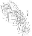
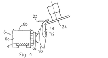
図1a、図2、図3及び図4は、キャリア6がレール4に沿って矢印方向8へ移動される胸肉処理ライン2を示す。各キャリア6は、所望であれば、得られた胸肉を載せることができるトレイ6bを備えたベースボディ6aを備える。ベースボディ6aの側部には、家禽部分を固定する部材6cが設けられ、その部材は詳細に図示していない軸を中心に制御された方法で回転可能であり、その軸は家禽部固定部材6cの中央を通って方向付けられ、ベースボディ6aの側部を横断している。家禽のいわゆるブレストキャップ10(皮膚がなく、鎖骨及び翼を有さず、リブを有し、背部を有しても有さなくてもよい胸部分)が、胸骨12の長手軸がほぼ鉛直になるように、家禽部固定部材6cに固定される。ここで、適切な固定に関しては、EP−A−0,254,332が参照される。図1aにおいて、ブレストキャップ10の外部胸肉14は、肩関節に対して付随した腱が延びた状態で、少なくとも肩関節に面する内部胸肉16の部分を露出させるために部分的に引き離す。図2から図4においては、外部胸肉14はない。内部胸肉16は本質的には、ほぼその生来の位置にあり、膜とともに胸骨12に付着している。各内部胸肉16から除去されるべき腱部分は、ほぼ三骨管の内側に延びている。内部胸肉16の長手方向は搬送方向8に対してほぼ直角である。
【0011】
胸肉処理ラインにおいて、フレーム20に固定された加工装置18がレール4に対して固定配置される。加工装置18はガイド22と、2つの回転カッター24、26(図3参照)とを備え、回転カッター24、26は各々の矢印28、30に従って反対方向へ、それぞれのモータ32、34によって駆動される。図1a、図3及び図4に示すように、モータ32、34の回転軸は鉛直線に対して傾いている。図1aでは、作業員を保護するため、保護フード40が回転カッター24、26の周りに配設されている。
【0012】
図1bは、内部胸肉16と、それに付着する腱16a、および腱付着部16bを示す。図において、矢印17a、17b、17c、17d及び17eは、本発明により、腱付着部16bの領域での切り込みが行われうる、異なる位置を示す。切り込み17aは腱付着部16bの外側の内部胸肉16にある。切り込み17bは腱付着部16bの端の内部胸肉16にある。切り込み17cは、腱付着部16bの内部胸肉16にある。切り込み17dは腱付着部16bの腱16aへの変わり目における内部胸肉16の端部にある。切り込み17eは腱16aにある。
【0013】
図1a、図2、図3及び図4に示すように、ブレストキャップ10は、ガイド22により、ブレストキャップ10の背側の襟骨(烏口骨)の領域で、矢印方向36(図2)へ押しのけられ、回転カッター24、26(図4)に対し、ある角度をもって位置決めされる。このようにして、回転カッター24、26が骨部分を切断し、望まれない骨残物を解放(リリース)するのを防止する。回転カッター24、26は、切り込み17a、17b、17c、17dあるいは17eのために、両方の内部胸肉16の長手方向に対してほぼ直角で、ブレストキャップ10の通路に前後して配置されるが、原則的には1つの回転カッターを使用することができるか、あるいは、1つ又はそれ以上の固定的又は弾性的に位置決めされカッターを使用することができる。更には、回転方向28、30を逆にすることも可能である。これらのカッターは、単に切断機能を有するだけではなく、ブレストキャップ10に与えられる切断力によりガイド22に対する位置決め機能をも有する。切り込みの位置及び高さは、ブレストキャップ10又は内部胸肉の寸法を考慮し、フレーム20上のモータ32、34を設ける場所を選択して調整できる。
【0014】
ブレストキャップ10に切り込みを入れた後は、内部胸肉16は手作業又は機械的に除去され、望まれない腱部分は胴体部分に残る。
【0015】
ここで、予定する切り込みは、実際には切り通し、又は切り通しに近いものであり、1つ又はそれ以上のカッターによるほか、ウォータージェットなどのその他の切断手段によっても得られることを認識すべきである。
【0016】
更に、切断手段は、コンベアの搬送路に沿って固定位置に配置されるばかりでなく、予定する切り込みを行うために、胴体部分の通路にキャリアの搬送と同期するように、可動とすることができることを認識すべきである。胴体部分は断続的に搬送されてもよいし、切り込みを入れるときに静止されてもよい。
【0017】
また更に、本発明では、加工装置18において、加工されるべき胴体部分から翼を落とすことは重要でないことも認識すべきである。もしも、胴体部分が翼を有すれば、これらの翼は適当なガイドによってたやすく回転カッター24、26又はその他の切断手段の作業範囲外に保持させ、翼があるにもかかわらず意図された切り込みが得られるようにすることができる。
【0018】
なお、腱の切り込みは、胸骨12とともにブレストキャップ10を矢印方向8と平行な方向へ搬送すること、およびブレストキャップ10の側から切り込みを入れられる内部胸肉又は腱部分と係合するカッター、又は、その他の切断手段を有することで得られることを認識すべきである。これを詳細に、図5及び図6にに示す実施形態を参照して説明する。
【0019】
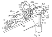
図5及び図6はEP−A−0,551,156に示されたタイプのキャリア40を示すもので、内部胸肉44を有する家禽の前半分42が矢印方向46へ搬送される。切断装置48が前半分42の搬送路に沿って固定的に配置されている。切断装置48は2つのディスク50a、50bを備え、これらは、点線で示されるそれぞれの軸52a、52bを介して、詳細には図示していない駆動装置によって矢印方向54a、54bの方向へ駆動される。軸52a、52bはそれぞれ静止ジャケット56a、56bの内側で回転し、静止ジャケット56a、56bには個々のディスク50a、50bの下方においてそれぞれギアリング58a、58bが設けられている。それぞれのディスク50a、50bには、それぞれの軸60a、60bを中心として回転可能に回転カッター64a、64bが配設され、それぞれギアリング58a、58bと係合する歯車62a、62b(見えない)が設けられている。ディスク50a、50bのエッジは切断を行わない。それぞれのディスク50a、50bがそれぞれ、反対方向54a、54bに回転することにより、カッター64a、64bは、それぞれ反対方向66a、66bへ回転し、カッター64a、64bの角速度はディスク50a、50bの角速度よりも大きく、かつ、ディスク50a、50bの周速度は好ましくは前半分42の搬送速度よりも大きい。ディスク50a、50bの回転は、カッター64a、64bが後続する前半分42と常に同じ場所で係合するようにキャリア40と同期させる。ディスク50a、50bは内部胸肉44をいくらか持ち上げる。カッター64a、64bは内部胸肉44の腱16aに、特に図6に示すように、とりわけ腱16aの腱付着部16b上方で内部胸肉44に切り込む又は切り通す。内部胸肉44の長手方向は搬送方向46とほぼ平行か、又は、少し傾いている。ディスク50a、50bには、前半分42の胸骨と内部胸肉44間との膜結合を破るための補助切断手段68a、68bが設けられていてもよい。
【0020】
図5及び図6の装置においてディスク50a、50bとカッター64a、64b、68a、68bによって得られる機能は、適切に配備された固定又は可動ガイドと、協働する固定又は可動切断手段とによっても得ることができ、その切断手段は、連続して、又は、断続的に移動されるキャリアに載置された胴体部分と係合することができる。この場合、まず胸骨と内部胸肉との間の膜結合は切断手段にて破られ、その後内部胸肉はガイドによって持ち上げられ、最後に腱又は内部胸肉は切断手段にて切り込みが入れられる。
【0021】
胴体部分はキャリアの上部に載せることではなく、キャリアの下部に載せることが可能となり、胸骨はキャリアから下方へ向けられる。この状況は、たとえばキャリア40を水平な縦軸又は横軸の周りに180度回転させることによって得られる。そのような状況において、内部胸肉の有効な持ち上げ(=胸骨までの距離の増加)は、重力がこの機能を満たすので省くことができる。
【0022】
本発明を、その好適な実施形態で図示して説明したが、本発明の範囲内でそこから離れてもよく、ここに開示した詳細事項に限定されないことを理解するべきである。
【図面の簡単な説明】
【図1a】本発明による加工装置を備えた胸肉処理ラインの一部の斜視図である。
【図1b】内部胸肉とそれに付着した腱の一部を示す側面図である。
【図2】本発明による加工装置のガイドの作用を示す部分断面側面図である。
【図3】図1による加工装置の詳細を示す斜視図である。
【図4】図1による加工装置の作用を示す一部断面側面図である。
【図5】本発明による加工装置の他の実施形態を示す斜視図である。
【図6】図5による加工装置の詳細を示す拡大図である。
【符号の説明】
4 レール
6 キャリア
6a ベースボディ
6b トレイ
6c 家禽固定部材
10 ブレストキャップ
14 外部胸肉
16、44 内部胸肉
16a 腱
16b 腱付着部
17a、17b、17c、17d、17e 切り込み
18 加工装置
22 ガイド
24、25 回転カッター
32、34 モータ
40 キャリア
42 前半分
48 切断装置
50a、50b ディスク
52a、52b、60a、60b 軸
56a、56b 静止ジャケット
58a、58b ギアリング
62a、62b 歯車
64a、64b カッター[0001]
BACKGROUND OF THE INVENTION
The present invention relates to a method for obtaining internal breast from a (slaughtered) carcass part of poultry. The invention also relates to an apparatus for processing a torso part to obtain internal breast from the torso part of a poultry.
[0002]
[Prior art]
The internal breasts of poultry such as chickens and turkeys, also called tenders, are located on the sternum on both sides of the cervical ridge, forming the most valuable meat part of poultry.
[0003]
As described in EP-A-0,695,506, removing internal breast meat from the poultry torso part by conventional techniques removes the wings from the torso part and delimits the border between the pubic bone and the sternum. This is accomplished by separating at the opening to form and then scraping the internal breast from the torso portion. As another method, according to US-A-5,314,374, the internal breast is partially cut from the body part from which the wings have been removed, and then the internal breast is removed from the body part with a grip member. It is to pull out the meat. As another method for removing the internal breast, according to EP-A-0,695,506, the membrane connection between the internal breast and the sternum is separated, the three bone canal (Canalis trioseus) is opened, and the tendon is cut. The internal breast is pulled apart by the wings that are connected to the internal breast via
[0004]
The disadvantage of the above-described method according to the prior art is that each removed internal breast remains connected with at least part of the tendon where the internal breast and associated wings in poultry are connected. In further processing of the internal breast into high value products for consumers, such as “nuggets”, tendons and sometimes at least some of their attachments to the internal breast must be removed. The reason is that meat consumers do not like these tendon parts. Removal of the tendon from the tendon attachment has usually been done by manually removing the tendon from the internal breast that is to be removed from the torso part or removed. This means that expensive manual labor is required, and only general reproducibility and quality are ensured, which does not contribute to sanitary internal breast meat processing, which is a drawback.
[0005]
U.S. Pat. No. 5,395,283 discloses an apparatus for automatically severing a portion from an internal breast carried by a tray from a tendon coupled to each internal breast. The internal breast is manually placed on the tray and positioned, and there is no solution to completely remove the unwanted tendon portion from the internal breast.
[0006]
[Problems to be solved by the invention]
It is an object of the present invention to provide a method and apparatus that provides an internal breast without an unwanted tendon portion, which does not require human action as described above.
[0007]
[Means for Solving the Problems]
To this end, the method according to the invention is characterized as described in the independent method claims, and the device according to the invention is characterized as described in the independent device claims. Preferred embodiments are described in the dependent claims.
[0008]
The method and device according to the present invention is automatic and uniform when the internal breast and its associated tendons, which are clearly shown in a site-specific representation, are still approximately (essentially) in their native positions. By making a sharp cut, you will substantially save labor and improve quality and process reproducibility.
[0009]
The claims and advantages will be better understood by reference to the following detailed description, and more readily understood when similar symbols are considered in conjunction with the accompanying drawings, which refer to like parts. The
[0010]
DETAILED DESCRIPTION OF THE INVENTION
FIGS. 1 a, 2, 3 and 4 show the
[0011]
In the breast processing line, the
[0012]
FIG. 1b shows the
[0013]
As shown in FIGS. 1 a, 2, 3, and 4, the
[0014]
After the incision is made in the
[0015]
Here, it should be recognized that the expected cut is actually cut or close to cut and can be obtained by one or more cutters as well as other cutting means such as a water jet. .
[0016]
Further, the cutting means is not only arranged at a fixed position along the conveyor conveyance path, but also movable to synchronize with the conveyance of the carrier in the passage of the fuselage part in order to make a predetermined cut. It should be recognized that it can be done. The body part may be transported intermittently or may be stationary when making a cut.
[0017]
Furthermore, it should be recognized that in the present invention, it is not important for the
[0018]
The incision of the tendon is performed by conveying the
[0019]
5 and 6 show a
[0020]
The functions obtained by the
[0021]
The torso portion can be placed on the lower portion of the carrier rather than on the upper portion of the carrier, and the sternum is directed downward from the carrier. This situation is obtained, for example, by rotating the
[0022]
While the invention has been illustrated and described in its preferred embodiments, it is to be understood that it may depart from the scope of the invention and is not limited to the details disclosed herein.
[Brief description of the drawings]
1a is a perspective view of a part of a breast processing line equipped with a processing device according to the invention. FIG.
FIG. 1b is a side view showing the internal breast and a portion of a tendon attached thereto.
FIG. 2 is a partial cross-sectional side view showing the operation of the guide of the processing apparatus according to the present invention.
FIG. 3 is a perspective view showing details of the processing apparatus according to FIG. 1;
4 is a partial cross-sectional side view showing the operation of the processing apparatus according to FIG. 1;
FIG. 5 is a perspective view showing another embodiment of the processing apparatus according to the present invention.
6 is an enlarged view showing details of the processing apparatus according to FIG. 5;
[Explanation of symbols]
4
Claims (13)
(a)内部胸肉が胴体部分のほぼ生来の位置にある間に、少なくとも肩部に面する内部胸肉部分と、この内部胸肉に付着した腱とを露出させる段階と、
(b)回転軸を有する少なくとも1つの回転駆動カッターを備えた切断手段を準備する段階と、
(c)胴体部分の襟骨の領域を前記切断手段の少なくとも1つのカッターの回転軸に対して所定の角度をなす位置に移動させるか、あるいは内部胸肉を持ち上げる段階と、
(d)前記切断手段によって、内部胸肉への腱の付着領域で、内部胸肉又は腱に切り込みを入れる段階と、
(e)胴体部分から内部胸肉を分離する段階とを備えることを特徴とする、前記方法。A method for obtaining an internal breast from a poultry torso using a processing device,
(A) exposing the internal breast portion facing at least the shoulder and the tendons attached to the internal breast while the internal breast is in a substantially natural position of the torso portion;
(B) providing a cutting means comprising at least one rotationally driven cutter having a rotational axis ;
(C) a step of lifting at least one or with respect to the axis of rotation of the cutter is moved to a position at a predetermined angle, or internal breast of the cutting means an area of the collar bone of the body portion,
(D) cutting the internal breast or tendon with the cutting means at the area of tendon attachment to the internal breast;
(E) separating the internal breast from the torso portion.
少なくとも胸骨と、襟骨と、ほぼ生来の位置にある内部胸肉と、この内部胸肉に付着した腱とを含む胴体部分を搬送すべく、搬送路に沿って搬送方向に移動される少なくとも1つのキャリアを有するコンベアを備えており、胸骨の対称面が搬送方向にほぼ直角な面内を延伸しており、前記装置が更に、
内部胸肉への腱の付着領域内で内部胸肉又は腱に切り込みを入れるべく、回転軸を有する少なくとも1つの回転駆動カッターを備えた切断手段と、
胴体部分の襟骨の領域を前記切断手段の少なくとも1つのカッターの回転軸に対して所定の角度をなす位置に移動させるように構成されたガイドとを備えていることを特徴とする、前記装置。A device for processing the body part of poultry,
At least one moved in the transport direction along the transport path to transport a torso portion including at least the sternum, the collarbone, the internal breast in a substantially native position, and a tendon attached to the internal breast Comprising a conveyor having two carriers, wherein the plane of symmetry of the sternum extends in a plane substantially perpendicular to the transport direction, the device further comprising:
A cutting means comprising at least one rotationally driven cutter having a rotation axis for incising the internal breast or tendon within the area of attachment of the tendon to the internal breast;
Said apparatus comprising: a guide configured to move a collar bone region of the torso portion to a position that forms a predetermined angle with respect to a rotational axis of at least one cutter of said cutting means. .
少なくとも胸骨とほぼ生来の位置にある内部胸肉とこの内部胸肉に付着した腱とを含む胴体部分を搬送すべく、搬送路に沿って搬送方向に移動される少なくとも1つのキャリアを有するコンベアを備えており、胸骨の長手方向がほぼ搬送方向と平行であり、前記装置が更に、
内部胸肉への腱の付着領域で、内部胸肉又は腱に切り込みを入れる切断手段を備えており、切断手段は、各々が回転軸を中心として回転可能な2つのディスクを備えており、該ディスクの各々には、回転カッターが回転軸を中心として回転可能に取り付けられており、該回転カッターの回転軸が、各ディスクの回転軸に対し、偏心して位置していることを特徴とする、前記装置。A device for processing the body part of poultry,
A conveyor having at least one carrier moved in a conveying direction along a conveying path to convey a torso portion including at least a breastbone and a tendon attached to the internal breast in a substantially natural position; The longitudinal direction of the sternum is substantially parallel to the transport direction, and the device further comprises
A cutting means for incising the internal breast or tendon at a region where the tendon is attached to the internal breast, the cutting means comprising two disks each rotatable about a rotation axis; A rotary cutter is attached to each of the disks so as to be rotatable about a rotation axis , and the rotation axis of the rotary cutter is located eccentrically with respect to the rotation axis of each disk . Said device.
Applications Claiming Priority (2)
| Application Number | Priority Date | Filing Date | Title |
|---|---|---|---|
| NL1012683A NL1012683C2 (en) | 1999-07-23 | 1999-07-23 | Method for recovering an inner fillet from a poultry carcass part, and device for processing the poultry carcass part. |
| NL1012683 | 1999-07-23 |
Publications (3)
| Publication Number | Publication Date |
|---|---|
| JP2001069904A JP2001069904A (en) | 2001-03-21 |
| JP2001069904A5 JP2001069904A5 (en) | 2007-08-16 |
| JP4598926B2 true JP4598926B2 (en) | 2010-12-15 |
Family
ID=19769630
Family Applications (1)
| Application Number | Title | Priority Date | Filing Date |
|---|---|---|---|
| JP2000218850A Expired - Lifetime JP4598926B2 (en) | 1999-07-23 | 2000-07-19 | Method for obtaining internal breast from poultry torso and apparatus for processing poultry torso |
Country Status (8)
| Country | Link |
|---|---|
| US (1) | US6736717B1 (en) |
| EP (1) | EP1070456B1 (en) |
| JP (1) | JP4598926B2 (en) |
| AT (1) | ATE261666T1 (en) |
| DE (1) | DE60008973T2 (en) |
| DK (1) | DK1070456T3 (en) |
| ES (1) | ES2215564T3 (en) |
| NL (1) | NL1012683C2 (en) |
Families Citing this family (32)
| Publication number | Priority date | Publication date | Assignee | Title |
|---|---|---|---|---|
| DE60322972D1 (en) * | 2002-12-20 | 2008-09-25 | Stork Pmt | Method and device for treating a poultry body part of slaughtered poultry |
| NL1022858C2 (en) † | 2003-03-06 | 2004-09-16 | Meyn Food Proc Technology Bv | Filleting street for poultry. |
| NL1029227C2 (en) | 2005-06-10 | 2006-12-12 | Meyn Food Proc Technology Bv | Method and device for harvesting an inner fillet of poultry. |
| EP1956919B1 (en) | 2005-12-09 | 2015-10-21 | Marel Stork Poultry Processing B.V. | Method and device for processing a carcass part of slaughtered poultry |
| NL1033122C2 (en) * | 2006-12-22 | 2008-06-24 | Stork P M T B V | Method and device for the separate harvesting of back skin and back meat from a carcass part of slaughtered poultry. |
| US8632380B2 (en) | 2010-01-26 | 2014-01-21 | Foodmate B.V. | Method and apparatus for removing a sleeve of meat from an animal part having bone with knuckles on each of its opposite ends |
| US8157625B2 (en) | 2010-01-26 | 2012-04-17 | Foodmate Bv | Method and apparatus for collecting meat from an animal part |
| NL2006075C2 (en) | 2011-01-26 | 2012-07-30 | Foodmate B V | Rotationally indexed article support for a conveyor system having an alignment station. |
| US8789684B2 (en) | 2010-04-19 | 2014-07-29 | Foodmate Bv | Rotatable article support for a conveyor |
| US8757354B2 (en) | 2010-04-19 | 2014-06-24 | Foodmate Bv | Turning block alignment |
| NL2004574C2 (en) | 2010-04-19 | 2011-10-20 | Foodmate B V | Rotatable article support for a conveyor. |
| NL2004573C2 (en) | 2010-04-19 | 2011-10-20 | Foodmate B V | Turning block alignment. |
| NL2004662C2 (en) * | 2010-05-04 | 2011-11-08 | Meyn Food Proc Technology Bv | A method for filleting poultry or poultry parts and a filleting system for such poultry or poultry parts. |
| DE102010035387A1 (en) * | 2010-08-20 | 2012-02-23 | Nordischer Maschinenbau Rud. Baader Gmbh + Co Kg | Apparatus and method for automatically cutting the wings of poultry bodies |
| DE102010047660B4 (en) * | 2010-09-30 | 2016-09-01 | Nordischer Maschinenbau Rud. Baader Gmbh + Co. Kg | Apparatus and method for completely detaching at least a portion of the breast cartilage from a poultry carcass freed from the breast meat |
| US8727839B2 (en) | 2011-01-21 | 2014-05-20 | Foodmate Bv | Poultry wing cutter for narrow pitch poultry lines |
| US8882571B2 (en) | 2011-01-26 | 2014-11-11 | Foodmate Bv | Method of deboning animal thighs for separating and collecting meat therefrom and apparatus for performing the method |
| EP2667728B1 (en) | 2011-01-26 | 2015-07-29 | Foodmate B.V. | Method of deboning animal thighs for separating and collecting meat there from and apparatus for performing the method |
| US8267241B2 (en) | 2011-01-26 | 2012-09-18 | Foodmate Bv | Rotationally indexed article support for a conveyor system having an alignment station |
| US8430728B2 (en) | 2011-02-14 | 2013-04-30 | Foodmate Bv | Special cut poultry wing cutter |
| ES2528232T3 (en) * | 2011-12-23 | 2015-02-06 | Nordischer Maschinenbau Rud. Baader Gmbh + Co. Kg | Device and procedure to completely separate breast fillets from the carcass already partially separated from the carcass of an eviscerated poultry body |
| EP2622962B1 (en) | 2012-01-31 | 2014-12-17 | Nordischer Maschinenbau Rud. Baader GmbH + Co. KG | Tendon separation apparatus and processing apparatus with such a tendon separation apparatus and method for automatic separation of tendons and/or tendon sections on inner breast filets |
| NL2009033C2 (en) | 2012-06-19 | 2013-12-23 | Foodmate B V | Weighing method and apparatus. |
| US8535124B1 (en) | 2012-10-17 | 2013-09-17 | Remington Holdings Llc | Poultry tender tendon clipper |
| NL2009718C2 (en) | 2012-10-29 | 2014-05-01 | Foodmate B V | Method of mechanically removing skin from animal parts. |
| US8808068B2 (en) | 2012-10-29 | 2014-08-19 | Foodmate Bv | Method of and system for automatically removing meat from an animal extremity |
| ES2661642T3 (en) * | 2013-04-26 | 2018-04-02 | Marel Meat Processing Inc. | A system for the treatment of housing parts |
| US9078453B2 (en) | 2013-11-01 | 2015-07-14 | Foodmate B.V. | Method and system for automatically deboning poultry breast caps containing meat and a skeletal structure to obtain breast fillets therefrom |
| US8961274B1 (en) | 2013-12-18 | 2015-02-24 | Foodmate Bv | Selective tendon cutter and method |
| EP3407727A1 (en) * | 2016-01-26 | 2018-12-05 | Foodmate B.V. | Method of mechanically harvesting inner and outer meat fillets from poultry carcass breast caps, and a device for carrying out the method |
| CN109832325B (en) * | 2017-11-26 | 2021-01-12 | 盐城高新区唯实农业发展有限公司 | Symmetrically-arranged pig foot tendon removing whole machine |
| CN113475561B (en) * | 2021-07-08 | 2022-09-02 | 龙俊 | Machine for removing bone from chicken feet |
Citations (4)
| Publication number | Priority date | Publication date | Assignee | Title |
|---|---|---|---|---|
| JPH05184281A (en) * | 1991-07-30 | 1993-07-27 | Mayekawa Mfg Co Ltd | Deboning method and deboner |
| JPH08168334A (en) * | 1994-07-21 | 1996-07-02 | Stork Pmt Bv | Method and device for removing fillet from body of killed poultry |
| JPH114655A (en) * | 1997-06-16 | 1999-01-12 | Ishikawajima Harima Heavy Ind Co Ltd | Hook part cutter for dark meat of poultry |
| JPH119181A (en) * | 1997-06-27 | 1999-01-19 | Majima Tekkosho:Kk | Chicken breast meat musculotendon excision apparatus |
Family Cites Families (13)
| Publication number | Priority date | Publication date | Assignee | Title |
|---|---|---|---|---|
| NL8601921A (en) * | 1986-07-24 | 1988-02-16 | Stork Pmt | MOUNTING SUPPORT. |
| US4873746A (en) * | 1988-01-25 | 1989-10-17 | Simon-Johnson Company | Method and apparatus for removing breast meat from poultry carcass |
| JPH0349639A (en) * | 1989-07-14 | 1991-03-04 | Fujie Kushida | Method for removing tendon of meat and tendon-removing vessel used in the same method |
| NL9200037A (en) * | 1992-01-10 | 1993-08-02 | Stork Pmt | METHOD AND APPARATUS FOR FILLING THE HULL OF A GENDER BIRD |
| US5411434A (en) * | 1992-03-24 | 1995-05-02 | Kays Engineering | Poultry shoulder and breast severing machine |
| US5370573A (en) * | 1993-05-26 | 1994-12-06 | B. C. Rogers Poultry, Inc. | Chicken breast slicing method and apparatus |
| US5314374A (en) | 1993-06-14 | 1994-05-24 | Jay Koch | Apparatus for removing tenders from a poultry carcass |
| JP2563877B2 (en) * | 1993-07-26 | 1996-12-18 | 株式会社ニイブロ | Method and device for cutting muscle tendons of chicken meat |
| US5395283A (en) | 1994-03-23 | 1995-03-07 | Gasbarro; Geno N. | Automatic tendon removal apparatus |
| EP1266574B1 (en) * | 1996-06-21 | 2008-01-16 | Mayekawa Manufacturing Co., Ltd. | System of automatically loading parts of poultry carcasses to a plurality of apparatus |
| JP3483712B2 (en) * | 1996-08-26 | 2004-01-06 | 株式会社前川製作所 | Breast meat separation method and device |
| JP3549679B2 (en) * | 1996-07-24 | 2004-08-04 | 株式会社前川製作所 | Breast meat separation method and device |
| JP3497476B2 (en) * | 2001-01-30 | 2004-02-16 | 株式会社前川製作所 | Method and apparatus for harvesting hollow carcasses |
-
1999
- 1999-07-23 NL NL1012683A patent/NL1012683C2/en not_active IP Right Cessation
-
2000
- 2000-07-14 DE DE60008973T patent/DE60008973T2/en not_active Expired - Lifetime
- 2000-07-14 EP EP00202538A patent/EP1070456B1/en not_active Expired - Lifetime
- 2000-07-14 ES ES00202538T patent/ES2215564T3/en not_active Expired - Lifetime
- 2000-07-14 DK DK00202538T patent/DK1070456T3/en active
- 2000-07-14 AT AT00202538T patent/ATE261666T1/en not_active IP Right Cessation
- 2000-07-19 JP JP2000218850A patent/JP4598926B2/en not_active Expired - Lifetime
- 2000-07-21 US US09/621,023 patent/US6736717B1/en not_active Expired - Lifetime
Patent Citations (4)
| Publication number | Priority date | Publication date | Assignee | Title |
|---|---|---|---|---|
| JPH05184281A (en) * | 1991-07-30 | 1993-07-27 | Mayekawa Mfg Co Ltd | Deboning method and deboner |
| JPH08168334A (en) * | 1994-07-21 | 1996-07-02 | Stork Pmt Bv | Method and device for removing fillet from body of killed poultry |
| JPH114655A (en) * | 1997-06-16 | 1999-01-12 | Ishikawajima Harima Heavy Ind Co Ltd | Hook part cutter for dark meat of poultry |
| JPH119181A (en) * | 1997-06-27 | 1999-01-19 | Majima Tekkosho:Kk | Chicken breast meat musculotendon excision apparatus |
Also Published As
| Publication number | Publication date |
|---|---|
| JP2001069904A (en) | 2001-03-21 |
| DE60008973D1 (en) | 2004-04-22 |
| EP1070456A1 (en) | 2001-01-24 |
| US6736717B1 (en) | 2004-05-18 |
| DK1070456T3 (en) | 2004-06-21 |
| NL1012683C2 (en) | 2001-01-24 |
| ES2215564T3 (en) | 2004-10-16 |
| ATE261666T1 (en) | 2004-04-15 |
| EP1070456B1 (en) | 2004-03-17 |
| DE60008973T2 (en) | 2004-08-12 |
Similar Documents
| Publication | Publication Date | Title |
|---|---|---|
| JP4598926B2 (en) | Method for obtaining internal breast from poultry torso and apparatus for processing poultry torso | |
| JP5538473B2 (en) | Method and apparatus for processing the body of slaughtered poultry | |
| EP1226758B1 (en) | Method and apparatus of separating poultry meat from bones | |
| US4827570A (en) | Method and apparatus for removing breast meat from poultry carcass | |
| US4873746A (en) | Method and apparatus for removing breast meat from poultry carcass | |
| JPH04126033A (en) | Method and device for mechanically bird taking out meat form body of killed edible | |
| US5188559A (en) | Method and apparatus for separating the legs from the back of a poultry carcass | |
| BRPI0608515B1 (en) | Method and device for processing slaughtered poultry carcass parts | |
| EP1064848A1 (en) | Apparatus for cutting off the arse of slaughtered poultry | |
| JPH0257894B2 (en) | ||
| JPH08168334A (en) | Method and device for removing fillet from body of killed poultry | |
| JP2008307064A (en) | Automatic boninig system of upper half slaughtered edible fowl | |
| HU197501B (en) | Method and device for parting slaughtered poultry | |
| CA2861942C (en) | Sinew removal device, processing device having such a sinew removal device, and method for the automatic removal of sinews and/or sinew portions situated on inner breast fillets | |
| JPH0748975B2 (en) | Poultry limb processing method | |
| JP2565470B2 (en) | Method for separating a wing from a bird's body and a device for carrying out the method | |
| DK200301124A (en) | Method and arrangement for the slaughter of fish, in particular of white meat fish | |
| JP4471311B2 (en) | Method and apparatus for separating chicken wings with wings | |
| JPH06339337A (en) | Method and equipment for removal of organ, gill, skul and backbone from front part of fish body | |
| JPH0767517A (en) | Method of processing body part of bird killed | |
| JP5384138B2 (en) | Method and apparatus for separating chicken wings with wings | |
| US3570047A (en) | Method for the removal of the liver from the belly cavity of fishes, in particular lean fishes | |
| JPH10150912A (en) | Leg processor for carcass processor | |
| JPH0823874A (en) | Hard scale remover from fish body |
Legal Events
| Date | Code | Title | Description |
|---|---|---|---|
| A521 | Request for written amendment filed |
Free format text: JAPANESE INTERMEDIATE CODE: A523 Effective date: 20070629 |
|
| A621 | Written request for application examination |
Free format text: JAPANESE INTERMEDIATE CODE: A621 Effective date: 20070629 |
|
| A977 | Report on retrieval |
Free format text: JAPANESE INTERMEDIATE CODE: A971007 Effective date: 20080826 |
|
| A131 | Notification of reasons for refusal |
Free format text: JAPANESE INTERMEDIATE CODE: A131 Effective date: 20080902 |
|
| A601 | Written request for extension of time |
Free format text: JAPANESE INTERMEDIATE CODE: A601 Effective date: 20081126 |
|
| A602 | Written permission of extension of time |
Free format text: JAPANESE INTERMEDIATE CODE: A602 Effective date: 20081201 |
|
| A521 | Request for written amendment filed |
Free format text: JAPANESE INTERMEDIATE CODE: A523 Effective date: 20090302 |
|
| A131 | Notification of reasons for refusal |
Free format text: JAPANESE INTERMEDIATE CODE: A131 Effective date: 20090818 |
|
| A601 | Written request for extension of time |
Free format text: JAPANESE INTERMEDIATE CODE: A601 Effective date: 20091112 |
|
| A602 | Written permission of extension of time |
Free format text: JAPANESE INTERMEDIATE CODE: A602 Effective date: 20091118 |
|
| A521 | Request for written amendment filed |
Free format text: JAPANESE INTERMEDIATE CODE: A523 Effective date: 20100218 |
|
| TRDD | Decision of grant or rejection written | ||
| A01 | Written decision to grant a patent or to grant a registration (utility model) |
Free format text: JAPANESE INTERMEDIATE CODE: A01 Effective date: 20100831 |
|
| A01 | Written decision to grant a patent or to grant a registration (utility model) |
Free format text: JAPANESE INTERMEDIATE CODE: A01 |
|
| A61 | First payment of annual fees (during grant procedure) |
Free format text: JAPANESE INTERMEDIATE CODE: A61 Effective date: 20100927 |
|
| R150 | Certificate of patent or registration of utility model |
Ref document number: 4598926 Country of ref document: JP Free format text: JAPANESE INTERMEDIATE CODE: R150 Free format text: JAPANESE INTERMEDIATE CODE: R150 |
|
| FPAY | Renewal fee payment (event date is renewal date of database) |
Free format text: PAYMENT UNTIL: 20131001 Year of fee payment: 3 |
|
| R250 | Receipt of annual fees |
Free format text: JAPANESE INTERMEDIATE CODE: R250 |
|
| R250 | Receipt of annual fees |
Free format text: JAPANESE INTERMEDIATE CODE: R250 |
|
| R250 | Receipt of annual fees |
Free format text: JAPANESE INTERMEDIATE CODE: R250 |
|
| R250 | Receipt of annual fees |
Free format text: JAPANESE INTERMEDIATE CODE: R250 |
|
| R250 | Receipt of annual fees |
Free format text: JAPANESE INTERMEDIATE CODE: R250 |
|
| R250 | Receipt of annual fees |
Free format text: JAPANESE INTERMEDIATE CODE: R250 |
|
| R250 | Receipt of annual fees |
Free format text: JAPANESE INTERMEDIATE CODE: R250 |
|
| EXPY | Cancellation because of completion of term |