JP4596870B2 - Extrusion device with weighing means - Google Patents
Extrusion device with weighing means Download PDFInfo
- Publication number
- JP4596870B2 JP4596870B2 JP2004273460A JP2004273460A JP4596870B2 JP 4596870 B2 JP4596870 B2 JP 4596870B2 JP 2004273460 A JP2004273460 A JP 2004273460A JP 2004273460 A JP2004273460 A JP 2004273460A JP 4596870 B2 JP4596870 B2 JP 4596870B2
- Authority
- JP
- Japan
- Prior art keywords
- extrusion
- expansion
- extrusion device
- contraction
- plunger
- Prior art date
- Legal status (The legal status is an assumption and is not a legal conclusion. Google has not performed a legal analysis and makes no representation as to the accuracy of the status listed.)
- Active
Links
- 238000001125 extrusion Methods 0.000 title claims description 112
- 238000005303 weighing Methods 0.000 title claims description 16
- 230000008602 contraction Effects 0.000 claims description 55
- 239000011345 viscous material Substances 0.000 claims description 34
- 230000007246 mechanism Effects 0.000 claims description 6
- 230000002093 peripheral effect Effects 0.000 claims description 4
- 239000012530 fluid Substances 0.000 claims description 3
- 239000000853 adhesive Substances 0.000 claims description 2
- 230000001070 adhesive effect Effects 0.000 claims description 2
- 239000000126 substance Substances 0.000 abstract description 2
- 238000000034 method Methods 0.000 description 15
- 230000008569 process Effects 0.000 description 15
- 230000008859 change Effects 0.000 description 4
- 238000003825 pressing Methods 0.000 description 4
- 230000009471 action Effects 0.000 description 3
- 239000002184 metal Substances 0.000 description 3
- 239000004033 plastic Substances 0.000 description 2
- 230000006837 decompression Effects 0.000 description 1
- 230000007423 decrease Effects 0.000 description 1
- 230000001419 dependent effect Effects 0.000 description 1
- 238000006073 displacement reaction Methods 0.000 description 1
- 230000000694 effects Effects 0.000 description 1
- 239000007788 liquid Substances 0.000 description 1
- 238000005259 measurement Methods 0.000 description 1
- 230000007420 reactivation Effects 0.000 description 1
- 238000007789 sealing Methods 0.000 description 1
- 239000007787 solid Substances 0.000 description 1
Images


Classifications
-
- B—PERFORMING OPERATIONS; TRANSPORTING
- B05—SPRAYING OR ATOMISING IN GENERAL; APPLYING FLUENT MATERIALS TO SURFACES, IN GENERAL
- B05C—APPARATUS FOR APPLYING FLUENT MATERIALS TO SURFACES, IN GENERAL
- B05C17/00—Hand tools or apparatus using hand held tools, for applying liquids or other fluent materials to, for spreading applied liquids or other fluent materials on, or for partially removing applied liquids or other fluent materials from, surfaces
- B05C17/005—Hand tools or apparatus using hand held tools, for applying liquids or other fluent materials to, for spreading applied liquids or other fluent materials on, or for partially removing applied liquids or other fluent materials from, surfaces for discharging material from a reservoir or container located in or on the hand tool through an outlet orifice by pressure without using surface contacting members like pads or brushes
- B05C17/015—Hand tools or apparatus using hand held tools, for applying liquids or other fluent materials to, for spreading applied liquids or other fluent materials on, or for partially removing applied liquids or other fluent materials from, surfaces for discharging material from a reservoir or container located in or on the hand tool through an outlet orifice by pressure without using surface contacting members like pads or brushes with pneumatically or hydraulically actuated piston or the like
-
- B—PERFORMING OPERATIONS; TRANSPORTING
- B05—SPRAYING OR ATOMISING IN GENERAL; APPLYING FLUENT MATERIALS TO SURFACES, IN GENERAL
- B05C—APPARATUS FOR APPLYING FLUENT MATERIALS TO SURFACES, IN GENERAL
- B05C17/00—Hand tools or apparatus using hand held tools, for applying liquids or other fluent materials to, for spreading applied liquids or other fluent materials on, or for partially removing applied liquids or other fluent materials from, surfaces
- B05C17/005—Hand tools or apparatus using hand held tools, for applying liquids or other fluent materials to, for spreading applied liquids or other fluent materials on, or for partially removing applied liquids or other fluent materials from, surfaces for discharging material from a reservoir or container located in or on the hand tool through an outlet orifice by pressure without using surface contacting members like pads or brushes
- B05C17/00553—Hand tools or apparatus using hand held tools, for applying liquids or other fluent materials to, for spreading applied liquids or other fluent materials on, or for partially removing applied liquids or other fluent materials from, surfaces for discharging material from a reservoir or container located in or on the hand tool through an outlet orifice by pressure without using surface contacting members like pads or brushes with means allowing the stock of material to consist of at least two different components
Abstract
Description
本発明は,接着剤等の粘性物質を貯蔵容器から押し出すための流体圧作動型の押し出し装置に関し,特に,ハウジング内に,粘性物質を貯蔵容器から押し出すための押し出し手段と,該押し出し手段により押し出すべき粘性物質の分量を予め設定するための計量手段とが配置され,押し出し手段が,圧力室からの圧力媒体により作動させる加圧ピストンを具え,該加圧ピストンが押し出し方向側に少なくとも1個のプランジャを有し,押し出し手段が押し出し装置の長手方向に可動に配置され,前記計量手段が,粘性物質の押し出し分量を調整するための調整手段と,押し出し手段と協働する拡縮部分と,該拡縮部分を終端位置から初期位置まで復帰させるための復帰手段とを具える押し出し装置に関するものである。 The present invention relates to a fluid pressure actuated extrusion device for extruding a viscous substance such as an adhesive from a storage container, and in particular, an extrusion means for extruding a viscous substance from a storage container into the housing, and the extrusion means to extrude. Metering means for presetting the amount of the viscous material to be set, and the pushing means comprises a pressurizing piston operated by a pressure medium from the pressure chamber, the pressurizing piston being at least one in the pushing direction side An extruding device having a plunger, wherein the extruding device is movably disposed in the longitudinal direction of the extruding device; the metering device includes an adjusting device for adjusting the amount of the viscous material to be extruded; The present invention relates to an extrusion device including return means for returning a portion from an end position to an initial position.
上述した構成を有する押し出し装置は,圧縮空気等の加圧流体により作動させてカートリッジ又はホースバッグ等の貯蔵容器から所定量の粘性物質を押し出すものである。粘性物質は,一成分系の場合には単一のカートリッジ,多成分系の場合には複数のカートリッジに保管される。押し出し装置は,ハウジングと,押し出し手段と,計量手段とを具える。押し出し装置は,少なくとも1個のカートリッジのための受け部材を有する。粘性物質は,押し出し手段によりカートリッジから押し出し可能である。多成分系の場合には,前端領域に配置されるミキサ等により押し出した成分を混合して使用可能な粘性物質とする。化学的接合等の用途では,成分毎に押し出すべき粘性物質の分量が特定される。押し出し装置の作業者は,計量手段により粘性物質を,所定の分量をもって正確・迅速にドリル孔等に導入することができる。計量手段は,分量を調整するための調整手段を具える。 The extrusion device having the above-described configuration is operated by a pressurized fluid such as compressed air to extrude a predetermined amount of viscous substance from a storage container such as a cartridge or a hose bag. The viscous material is stored in a single cartridge in the case of a one-component system and in a plurality of cartridges in the case of a multi-component system. The extrusion device includes a housing, extrusion means, and weighing means. The extrusion device has a receiving member for at least one cartridge. The viscous material can be pushed out of the cartridge by the pushing means. In the case of a multi-component system, the components extruded by a mixer or the like arranged in the front end region are mixed to obtain a usable viscous material. In applications such as chemical bonding, the amount of viscous material to be extruded is specified for each component. The operator of the extrusion device can introduce the viscous substance into the drill hole or the like accurately and quickly with a predetermined amount by the measuring means. The weighing means comprises adjusting means for adjusting the quantity.
米国特許第5020693号明細書(特許文献1)は空圧式押し出し装置を記載しており,この装置は,ハウジングと,粘性物質を保管及び押し出すための縦型押し出し部分を有する押し出し手段と,押し出し手段により押し出すべき粘性物質の分量を予め設定するための計量手段と,押し出し手段を作動するためのトリガユニットとを具える。計量手段は復帰手段,分量調整のための調整手段及び押し出し部分と協働する拡縮部分を有し,該拡縮部分は復帰手段により終端位置から初期位置へ移動可能とされている。押し出し部分は長手方向に可動としてハウジングに配置され,粘性物質を充填したカートリッジ等を押圧するための複数のプランジャを具える。計量手段は,押し出し部分の長手方向に変位可能にハウジングに配置した少なくとも1個のストッパを具え,このストッパはクランプねじによりハウジングに対して固定可能とされている。
上述した従来技術は,ねじ固定可能なストッパが復帰手段により少なくとも部分的に変位することがあり,その結果として,予め設定した押し出し分量が変化する恐れがある。更に,調整部分による分量調整が不便であり,しかも不正確である。 In the prior art described above, the stopper that can be screwed may be displaced at least partially by the return means, and as a result, the preset amount of extrusion may change. Furthermore, the amount adjustment by the adjustment part is inconvenient and inaccurate.
本発明の課題は,押し出し分量を容易かつ正確に調整可能であり,復帰手段の作動等における分量の不所望な変化を確実に防止可能であり,しかも経済的に製造可能な流体圧作動型の押し出し装置を提案することにある。 An object of the present invention is to make it possible to easily and accurately adjust the amount of extrusion, to reliably prevent undesired changes in the amount during operation of the return means, etc., and to be economically manufacturable. It is to propose an extrusion device.
この課題を解決するため,本発明に係る押し出し装置は,請求項1に記載した事項を特徴とするものである。また,好適な実施形態は,従属請求項に記載したとおりである。 In order to solve this problem, an extrusion device according to the present invention is characterized by the matters described in claim 1. Preferred embodiments are as described in the dependent claims.
本発明に係る押し出し装置において,計量手段は,押し出し装置の長手方向に固定された保持部分と,押し出し装置の長手方向で可動とする連動部分とを具える。加圧ピストンにガイド管を配置する。計量手段の連動部分をガイド管に連結するために,拡縮部分は一方では計量手段における連動部分の遊端に配置され,他方では押し出し手段のガイド管内に固定可能とする。 In the extrusion device according to the present invention, the measuring means includes a holding portion fixed in the longitudinal direction of the extrusion device and an interlocking portion movable in the longitudinal direction of the extrusion device. A guide tube is disposed on the pressure piston. In order to connect the interlocking part of the measuring means to the guide tube, the expansion / contraction part is arranged on the free end of the interlocking part on the measuring means on the one hand and can be fixed in the guide tube of the pushing means on the other hand.
本発明による押し出し装置においては,押し出し工程で押し出すべき分量に直接的に関連するストロークを測定する。ストロークの測定は純機械的に行われ、完全に圧力媒体により制御されるものである。電子的な測定手段及び電子制御が不要であるため,押し出し装置には圧力媒体の他にエネルギ源は不要である。したがって,本発明による押し出し装置は優れた有用性を有すると共に,押し出した粘性物質を正確かつ迅速に計量することができる。 In the extrusion apparatus according to the present invention, the stroke directly related to the amount to be extruded in the extrusion process is measured. The measurement of the stroke is purely mechanical and is completely controlled by the pressure medium. Since electronic measuring means and electronic control are not required, the extrusion device requires no energy source in addition to the pressure medium. Therefore, the extrusion apparatus according to the present invention has excellent utility and can accurately and rapidly meter the extruded viscous substance.
押し出し装置の長手方向に固定された計量手段の保持部分はカバープレートに固定され,保持部分は調整手段により軸線を中心として旋回可能であるが,押し出し装置の長手方向に占める位置は変わらない。押し出し装置の長手方向に可動とする計量手段の連動部分は,調整手段により軸線を中心として旋回可能であり,押し出し手段と連結した状態では押し出し装置の長手方向に可動とする。復帰手段は,一方において計量手段の保持部分に固定されるか,又は少なくとも計量手段の保持部分の領域に固定され,他方では押し出し装置の長手方向に可動とする拡縮部分に固定されるか,又は少なくとも可動とする拡縮部分の領域に固定される。 The holding portion of the measuring means fixed in the longitudinal direction of the extrusion device is fixed to the cover plate, and the holding portion can be pivoted about the axis by the adjusting means, but the position occupied in the longitudinal direction of the extrusion device does not change. The interlocking portion of the weighing means that is movable in the longitudinal direction of the extrusion device can be pivoted about the axis by the adjusting device, and is movable in the longitudinal direction of the extrusion device when connected to the extrusion device. The return means is fixed on the one hand to the holding part of the weighing means, or at least fixed to the area of the holding part of the weighing means and on the other hand to the expansion / contraction part which is movable in the longitudinal direction of the extrusion device, or It is fixed at least to the region of the expansion / contraction portion that is movable.
加圧ピストン及び少なくとも1個のプランジャが前進すべきストロークは計量手段の調整手段により設定される。少なくとも1個のプランジャの遊端には押圧プレートが配置され,この押圧プレートは保管貯蔵容器の容量に作用する。粘性物質の押し出し分量は,ストローク及び貯蔵容器の断面積により決定される。押し出し装置のグリップに配置したトリガ等の操作ノブを操作すると,圧力室に圧力媒体が供給され,同時に,拡縮部分がガイド管内に固定される。押し出し装置の長手方向に可動とした計量手段の連動部分は,加圧ピストンにより更に圧力が増大すると押し出し方向に移動し,所定のストロークを前進すると共に,拡縮部分が押し出し工程の終端位置に到達する。引き続いて圧力室が減圧され,拡縮部分とガイド管との係合が解除される。拡縮部分及び計量手段の連動部分は,復帰手段により拡縮部分の終端位置から初期位置まで移動する。計量手段が復帰しても加圧ピストンが移動しないため,加圧ピストンは次の押し出し工程のための位置に止まる。すなわち,押し出し装置は,次の押し出し工程のために使用可能となる。押し出すべき粘性物質の分量に所望の変更がある場合にのみ,計量手段における調整手段を調整するものである。 The stroke that the pressure piston and at least one plunger should advance is set by the adjusting means of the metering means. A pressing plate is arranged at the free end of at least one plunger, which pressing plate acts on the capacity of the storage container. The amount of viscous material extruded is determined by the stroke and the cross-sectional area of the storage container. When an operation knob such as a trigger arranged on the grip of the extrusion device is operated, a pressure medium is supplied to the pressure chamber, and at the same time, the expansion / contraction portion is fixed in the guide tube. The interlocking part of the metering means that is movable in the longitudinal direction of the extrusion device moves in the extrusion direction when the pressure is further increased by the pressurizing piston, advances a predetermined stroke, and the expansion / contraction part reaches the end position of the extrusion process. . Subsequently, the pressure chamber is decompressed, and the engagement between the expansion / contraction portion and the guide tube is released. The expansion / contraction portion and the interlocking portion of the measuring means are moved from the end position of the expansion / contraction portion to the initial position by the return means. Since the pressure piston does not move even when the metering means returns, the pressure piston stops at the position for the next extrusion process. That is, the extrusion device can be used for the next extrusion process. The adjusting means in the measuring means is adjusted only when there is a desired change in the amount of viscous material to be pushed out.
僅かな個別部材を具えるコンパクトな構造の押し出し手段を実現するため,ガイド管は少なくとも1個のプランジャの一部として構成するのが有利である。 In order to realize a compactly structured push-out means with few individual members, the guide tube is advantageously constructed as part of at least one plunger.
拡縮部分は圧力媒体により半径方向に拡径可能とするのが好適である。拡縮部分はソリッドゴム球等の弾性素子とする。この弾性素子は,圧力媒体による荷重の作用下で半径方向に拡径すると共に,計量手段の連動部分と少なくとも1個のプランジャとの間に固定を実現する。圧力媒体により拡縮部分に生じる圧力が軽減されると,拡縮部分は当初の半径方向伸長に後退し,復帰手段により終端位置から初期位置へ移動可能となる。 It is preferable that the expansion / contraction portion can be radially expanded by a pressure medium. The expansion / contraction portion is an elastic element such as a solid rubber ball. This elastic element expands in the radial direction under the action of a load by the pressure medium, and realizes fixation between the interlocking portion of the measuring means and at least one plunger. When the pressure generated in the expansion / contraction portion is reduced by the pressure medium, the expansion / contraction portion retreats to the initial radial extension, and can be moved from the terminal position to the initial position by the return means.
拡縮部分は半径方向に延在する少なくとも1個の開口を具え,スリーブ部材の外周は弾性を有する伸長可能なカバーにより包囲されるのが好適である。空気圧式押し出し装置の場合,拡縮部分は膨張可能なベロー等として形成される。拡縮部分は少なくとも1個のプランジャ内に配置され,拡縮部分の外周面とプランジャの内周面との間隔を僅かな値に保つことにより,プランジャで拡縮部分の可動性を確保する。したがって,カバーは圧力媒体の作用による極く僅かな荷重を有するだけである。カバーはゴム又はプラスチック等から成形され,スリーブ部材等にシュリンク結合される。スリーブ部材は金属等から製造され,押し出し方向に気密のカバー部材を具える。したがって,スリーブ部材に導入される圧力媒体は,カバーを拡径するために,半径方向に延在する少なくとも1個の開口を通じてのみカバー内部に供給可能である。拡縮部分は,好適には管状断面を有する少なくとも1個のプランジャに固定される。圧力媒体の圧力が低下すると,直ちにカバー内の圧力媒体は少なくとも1個の開口を通じて再びスリーブ部材に環流し,拡縮部分が縮径する。 Preferably, the expansion / contraction portion comprises at least one opening extending in the radial direction, and the outer periphery of the sleeve member is surrounded by an extensible cover having elasticity. In the case of a pneumatic extrusion device, the expansion / contraction part is formed as an inflatable bellows or the like. The expansion / contraction part is disposed in at least one plunger, and the distance between the outer peripheral surface of the expansion / contraction part and the inner peripheral surface of the plunger is kept at a slight value, thereby ensuring the mobility of the expansion / contraction part by the plunger. Therefore, the cover has only a slight load due to the action of the pressure medium. The cover is molded from rubber or plastic and is shrink-bonded to a sleeve member or the like. The sleeve member is made of metal or the like, and includes an airtight cover member in the extrusion direction. Therefore, the pressure medium introduced into the sleeve member can be supplied to the inside of the cover only through at least one opening extending in the radial direction in order to expand the diameter of the cover. The expansion / contraction portion is preferably secured to at least one plunger having a tubular cross section. When the pressure of the pressure medium decreases, the pressure medium in the cover immediately circulates back to the sleeve member through at least one opening, and the diameter of the expansion / contraction portion is reduced.
ハウジング内の圧力室と拡縮部分とを接続するため,流路が連動部分を貫通し,好適には計量手段の保持部分を更に貫通する配置とするのが有利である。押し出し手段に作用すると,圧力媒体は圧力室から流路を通じて拡縮部分に供給され,プランジャで拡縮部分を固定する。圧力媒体は,減圧により拡縮部分から再び圧力室に搬送される。気密性を確保するための構造的な措置として,ハウジングに対して加圧ピストンを密閉するだけで十分である。 In order to connect the pressure chamber in the housing and the expansion / contraction part, it is advantageous that the flow path penetrates the interlocking part and preferably further penetrates the holding part of the measuring means. When acting on the pushing means, the pressure medium is supplied from the pressure chamber to the expansion / contraction portion through the flow path, and the expansion / contraction portion is fixed by the plunger. The pressure medium is again conveyed from the expansion / contraction portion to the pressure chamber by decompression. As a structural measure to ensure hermeticity, it is sufficient to seal the pressure piston against the housing.
計量手段は,調整手段により調整可能な第1制御面を具える構成とするのが好適である。第1制御面は,計量手段により押し出し工程で許容されるべき最大ストロークに一致する勾配を有する。第1制御面は連続的に延在するのが特に有利である。それにより,所定の領域を通じた分量の任意の調整が可能となる。第1制御面は全周に亙って延在させない配置とするのが有利である。作業者が調整手段を回しすぎるのを防ぐため,ストッパを具えることができる。計量手段の調整手段にはマーキング手段を取り付けるのが好適である。作業者は,マーキング手段により押し出すべき粘性物質の所望する分量を容易に調整することができる。 It is preferable that the measuring means includes a first control surface that can be adjusted by the adjusting means. The first control surface has a slope that corresponds to the maximum stroke to be allowed in the extrusion process by the metering means. It is particularly advantageous for the first control surface to extend continuously. Thereby, it is possible to arbitrarily adjust the quantity through a predetermined area. The first control surface is advantageously arranged so as not to extend over the entire circumference. A stopper can be provided to prevent the operator from turning the adjusting means too much. It is preferable to attach marking means to the adjustment means of the weighing means. The operator can easily adjust the desired amount of the viscous material to be pushed out by the marking means.
計量手段の連動部分はスリーブと,このスリーブに固く結合した管状部材とを具え,スリーブの外側に第1制御面を配置するのが好適である。連動部分のスリーブは,計量手段の保持部分上で滑動することができる。スリーブは円形の外周断面を有するのが有利であり,この外周断面には第1制御面を形成する。スリーブは,押し出し装置の長手方向で最大移動を限定するためのストッパを具えるのが好適である。計量手段の連動部分のスリーブに設けたストッパは,計量手段の保持部分に設けた別のストッパと協働することができる。したがって,押し出し装置の有用性は,故障時又は機械的な最大想定ストロークを超えた場合でも確保される。 Preferably, the interlocking portion of the metering means comprises a sleeve and a tubular member rigidly connected to the sleeve, and the first control surface is arranged outside the sleeve. The sleeve of the interlocking part can slide on the holding part of the metering means. The sleeve advantageously has a circular outer cross section, which forms a first control surface. The sleeve is preferably provided with a stopper for limiting the maximum movement in the longitudinal direction of the extrusion device. The stopper provided on the sleeve of the interlocking portion of the measuring means can cooperate with another stopper provided on the holding portion of the measuring means. Therefore, the usefulness of the extrusion device is ensured even in the event of a failure or when the mechanical maximum stroke is exceeded.
圧力室を減圧するためのリリーフ弁を押し出し手段のハウジングに配置し,このリリーフ弁は計量手段における第1制御面により制御される機構を介して作動可能とするのが有利である。リリーフ弁は押し出し装置の圧力室で直ちに減圧を可能にするため,押し出し手段の押し出し方向における移動は瞬時に停止する。リリーフ弁を作動するための機構は,計量手段により作動可能とした傾動レバー等として形成する。押し出し手段が所定のストロークを前進すると,制御面は傾動レバーの端部に接触する。傾動レバーはリリーフ弁を開放し,圧力室に留まる圧力媒体を圧力室から逃す。液体の圧力媒体を使用する場合には,ハウジングのリリーフ弁に集合管を接続し,圧力媒体を回収するのが有利である。 Advantageously, a relief valve for depressurizing the pressure chamber is arranged in the housing of the push-out means and this relief valve is operable via a mechanism controlled by the first control surface in the metering means. Since the relief valve can immediately reduce the pressure in the pressure chamber of the extrusion device, the movement of the extrusion means in the extrusion direction stops instantaneously. The mechanism for operating the relief valve is formed as a tilting lever or the like that can be operated by the measuring means. When the push-out means advances a predetermined stroke, the control surface comes into contact with the end of the tilting lever. The tilting lever opens the relief valve and releases the pressure medium remaining in the pressure chamber from the pressure chamber. When using a liquid pressure medium, it is advantageous to connect the collecting pipe to the relief valve of the housing and recover the pressure medium.
計量手段のための復帰手段は,円筒形状のコイルばねで構成するのが好適である。計量手段の固定された保持部分と拡縮部分との間にコイルばねを配置することにより,押し出し工程においてコイルばねは引き伸ばされる。圧力が降下すると共に拡縮部分の係合が解除されると,拡縮部分及び計量手段の連動部分がばねの復元力により終端位置から初期位置まで復帰する。 The return means for the weighing means is preferably constituted by a cylindrical coil spring. By arranging the coil spring between the fixed holding part and the expansion / contraction part of the measuring means, the coil spring is stretched in the extrusion process. When the pressure drops and the engagement of the expansion / contraction portion is released, the expansion / contraction portion and the interlocking portion of the measuring means are returned from the terminal position to the initial position by the restoring force of the spring.
計量手段の第1部分では圧力室と拡縮部分との間,又は圧力室と拡縮部分を制御するための流路との間の接続部分に制御バルブを配置するのが好適である。制御バルブにより接続部分の閉鎖が可能となり,計量手段は不作動になると共に,本発明に係る押し出し装置による押し出し又は連続的な押し出し工程が実現可能となる。制御バルブを制御するために,ハウジングに第2制御面を配置するのが好適である。第2制御面は,計量手段の調整手段を設けたハウジングのカバープレート等に形成する。調整手段により,計量手段が一方では押し出すべき粘性物質の異なる分量に適合させ,他方では押し出し装置の連続運転モードを選択可能とする。 In the first part of the metering means, it is preferable to arrange a control valve at a connection part between the pressure chamber and the expansion / contraction part or between the pressure chamber and the flow path for controlling the expansion / contraction part. The control valve enables the connection part to be closed, the metering means becomes inoperable, and the extrusion or continuous extrusion process by the extrusion device according to the present invention can be realized. In order to control the control valve, a second control surface is preferably arranged on the housing. The second control surface is formed on the cover plate of the housing provided with the adjusting means for the weighing means. By means of the adjusting means, the measuring means is adapted on the one hand to different quantities of the viscous material to be extruded, and on the other hand, the continuous operation mode of the extrusion device can be selected.
押し出し装置の長手方向におけるプランジャの移動量を示すため,移動量測定手段をハウジング又は少なくとも1個のプランジャに配置するのが有利である。測定手段はマーキング手段及び表示素子等を有し,表示素子はハウジングに対する押し出し手段の変位に応じて位置を表示し,押し出し装置で押し出すべき粘性物質の残量又は既出量を表示する。マーキングはハウジングの外側等に刻印又は押印される。表示素子は少なくとも1個のプランジャと結合したロッド等とし,プランジャが前進したストロークに応じて共に移動する。 In order to show the amount of movement of the plunger in the longitudinal direction of the extrusion device, it is advantageous to arrange the movement measuring means on the housing or at least one plunger. The measuring means includes a marking means, a display element, and the like. The display element displays the position according to the displacement of the pushing means with respect to the housing, and displays the remaining amount or the amount of the viscous substance to be pushed out by the pushing device. The marking is stamped or stamped on the outside of the housing. The display element is a rod or the like coupled to at least one plunger, and moves together according to the stroke of the plunger.
以下,本発明を図示の実施形態について更に具体的に説明する。なお,図1〜図6は本発明を空圧作動型押し出し装置11に適用した実施形態を示すものであるが,他の圧力媒体についても基本的に同一の構成とすることが可能である。
Hereinafter, the present invention will be described more specifically with reference to the illustrated embodiments. 1 to 6 show an embodiment in which the present invention is applied to a pneumatically operated
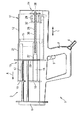
本発明による押し出し装置11は,例えば手持式装置1内に配置する。手持式装置1は,押し出し装置11以外にも,グリップ2と,二成分用カートリッジ等として構成された貯蔵容器のための受け部材3とを具える。受け部材3は,押し出し方向側で接続プレート6により限定される。接続プレート6には,押し出し装置11によりカートリッジから押し出された各成分を混合するためのミキサ(図示せず)を内蔵する。これらの成分は,ミキサ内で互いに混合することにより,接着等に使用可能な粘性物質を生成する。
The
圧力媒体としての圧縮空気を,グリップ2に接続した導管4を介して押し出し装置11に供給可能とする。圧縮空気を押し出し装置11に供給する通路内には,押し出し装置11を作動させるための手動操作部材5を配置する。操作部材5は,その操作により圧縮空気を押し出し装置11に供給するものである。
Compressed air as a pressure medium can be supplied to the
押し出し装置11のハウジング12内には,押し出し手段13と,計量手段14とを配置する。計量手段14は,押し出し手段13によりカートリッジから押し出すべき粘性物質の分量を予め設定するものである。押し出し手段13は加圧ピストン15を具える。加圧ピストン15には,押し出し方向A側で,カートリッジから第1成分を押し出すための第1プランジャ16と,カートリッジから第二成分を押し出すための第2プランジャ17とを配置する。第1プランジャ16を押し出し手段13のためのガイド手段として機能する管状部材で構成し,第2プランジャ17は金属又はプラスチック等で成形した円形断面のロッド部材で構成する。プランジャ16,17の先端には,それぞれ押圧プレート18,19を配置する。プランジャ16,17は,押し出し装置11の初期位置において,ハウジング12のフロントカバー20を貫通している。
In the
押圧プレート19に配置した連動ロッド21は,押し出し装置11のハウジング12に配置したマーキング手段22と共に,既に押し出した分量を表示するための測定手段23を形成する。
The interlocking
計量手段14は,押し出し工程において押し出し装置11による粘性物質の押し出し量を調整するための回転ノブとして構成した調整手段26と,第1プランジャ16と協働する膨張可能なベローで構成した拡縮部分27と,コイルばね28で構成した復帰手段とを有する。計量手段14は,押し出し装置11の長手方向Lに固定された保持部分29と,押し出し装置11の長手方向Lに可動とした連動部分30とを更に具える。計量手段14の保持部分29及び連動部分30は,調整手段26により中心軸線42を中心に旋回可能とする。拡縮部分27は,押し出し方向A側に位置する管状部材31の先端に配置する。管状部材31は,管状部材31に固定したスリーブ32と共に計量手段14の連動部分30を形成する。スリーブ32に形成した第1制御面の機能及び形状等は,後述するとおりである。調整手段26を保護するため,カバープレート33には,ハウジング12から突出するカラー34を設ける。
The metering means 14 includes an adjusting means 26 configured as a rotary knob for adjusting the amount of viscous material extruded by the
カバープレート33は,計量手段14の保持部分29を部分的に係合させるための受け36を具える。受け36は,制御バルブ38を制御するための第2制御面37を有する。計量手段14の保持部分29が調整手段26により回動し,制御バルブ38が計量手段14の保持部分29における接続部分39に押入すると,本実施形態では点40(図4参照)の方向に制御バルブ38が整列される。この場合,圧縮空気は管状部材31により作られた流路41を通じて拡縮部分27に流れることができず,拡縮部分27を第1プランジャ16に係合させることができない。
The
図3a〜図3cを参照して,本発明の押し出し装置11を使用しての押し出し工程における3種の作業状態に関連して各構成要素の機能について説明する。図3aは,本来の初期位置にある押し出し装置11を示す。初期位置において,プランジャ16,17は,押し出し方向Aとは反対方向へ可能な限り遠くまで復帰変位している。初期位置では,手持式装置1の受け部材3にカートリッジ等を挿入することができる。調整手段26を中心軸線42の周りで矢51方向に回動することにより,計量手段14の連動部分30が前進すべきストロークEを調整することにより,カートリッジから押し出すべき粘性物質の押し出し量を設定する。操作部材5を操作すると,圧縮空気が圧力室52に供給される。計量手段14における保持部分29を調整することにより,制御バルブ38は流路41を通じて圧縮空気を拡縮部分27まで供給することができる。その結果,拡縮部分27が半径方向に拡径し,計量手段14の連動部分30は圧力室52内の僅かな圧力上昇でも第1プランジャ16に固定される。圧力室52内の圧力が上昇すると,押し出し手段13全体は押し出し方向Aに変位する。第1プランジャ16に連結するため,計量手段14の連動部分30も押し出し方向Aに向けて移動すると共に,カートリッジから粘性物質が押し出しされる。コイルばね28は,一方では調整手段26の領域又は計量手段14の保持部分29に固定され,他方では拡縮部分27又は計量手段14の連動部分30の遊端領域に固定される。コイルばね28は押し出し工程において伸長し,押し出し方向Aとは反対方向に作用するばね力を生じる。
With reference to FIGS. 3a to 3c, the function of each component will be described in relation to the three types of working states in the extrusion process using the
第1制御面35がスリーブ32で接触ホイール56に接触すると,押し出し手段13及び計量手段14の連動部分30が所定のストロークEを前進すると共に,カートリッジから所定分量の粘性物質を押し出す。図3bに示すプランジャ16,17の位置と,図3aに示すプランジャ16,17の位置との間の距離Fは,ストロークEと一致する。拡縮部分27は終端位置を占める。制御面35が機構57の接触ホイール56に接触すると,2個の傾動素子58,59を通じてハウジング12に設けたリリーフ弁60が開放すると共に,圧力室52内の圧縮空気を逃がすことができる。これにより粘性物質の第1押し出し工程が終了し,所望分量がカートリッジから押し出しされる。スリーブ32はストッパ61を具え,該ストッパ61は計量手段14の保持部分29に設けたストッパ62と協働する。これらのストッパ61,62は,圧力室52の排気が故障した場合,必然的に継続する押し出し工程で計量手段14の連動部分30が計量手段14の保持部分30から離脱し,計量手段14及び押し出し装置11が機能不全となることを防止する。
When the
圧力室52内の圧力降下により,拡縮部分27に残る圧縮空気は流路41を通じて圧力室52に逃れる。その際,拡縮部分27は当初の半径方向位置を占め,拡縮部分27と第1プランジャ16との係合が解除される。コイルばね28に蓄えられたばね力により,計量手段14の連動部分30及び拡縮部分27は本来の初期位置に復帰する。この計量手段14の位置は,図3cに示すとおりである。制御面35と機構57の接触ホイール56との接触が中断され,リリーフ弁60が閉じる。その際,押し出し手段13は位置を変えない。計量手段13及び押し出し装置11は,押し出し装置11を再作動するための初期位置を占める。調整手段26を調整することなく,押し出し装置11を再作動すると,等量の押し出すべき粘性物質がカートリッジから押し出しされる。カートリッジが完全に空になるか,又は加圧ピストン15がフロントカバー20に直面するまで,押し出し工程を繰り返すことができる。
The compressed air remaining in the expansion /
図5a及び図5bは,第1制御面35を有するスリーブ32の側面図及び正面図である。第1制御面35の勾配はほぼ一定に上昇し,第1制御面35の最大リフト量Sは最大ストロークEと一致する。前述したとおり,最大ストロークEは,所定分量の粘性物質を押し出すための計量手段14により調整可能である。第1制御面35は,330°の角度に亙りスリーブ32の外周に沿って設けられ,ストッパ66として機能するオフセットを具える。作業者は調整手段26を操作し,第2可動部分30により前進可能なストロークをゼロから最大値Sまでの範囲内で調整することができる。ストッパ66を配置したことにより,調整手段26の不所望の過回転が防止され,スリーブ32が半径方向の終端位置に達したことを作業者に触覚的に報知する。更に,計量手段14は調整手段26により押し出し装置11の連続運転に調整可能である。作業者がグリップ2で操作部材5を作動するか又はカートリッジが空になるまで,粘性物質がカートリッジから押し出しされる。連続運転ポジションはスリーブ32の外周領域67に位置する。
FIGS. 5 a and 5 b are a side view and a front view of the
図6は,拡縮部分27の細部を示す断面図である。第1プランジャ16に配置した拡縮部分27は金属製のスリーブ部材71を有し,このスリーブ部材71は半径方向外方に延在する2個の開口72を具える。スリーブ部材71上にゴム製のカバー73がシュリンク接合され,スリーブ部材71の端部を包囲する。押し出し方向A側に位置するスリーブ部材71の端部には,スリーブ部材71を密閉するためのカバー74をねじ固定する。スリーブ部材71の対向する端部には,同様に密閉してスリーブ形状の接続素子75をねじ固定する。接続素子75は,スリーブ部材71を管状部材31の遊端に連結すると共に,拡縮部分27の復帰手段として供するコイルばねに係る固定点76を与える。グリップ2で操作部材5を作動すると,流路41を形成する管状部材31を通じた圧縮空気は圧力室52により拡縮部分27に流入する。圧縮空気は,開口72を通じてスリーブ部材71とカバー73との中間スペースに流入する。カバー73は半径方向に拡径すると共に,拡縮部分27を管状プランジャ16の内壁に固定する。リリーフ弁60の開放により圧力室52内に圧力降下が生じると,圧縮空気はスリーブ部材71とカバー73との中間スペースから開口72及び流路41を通じて再び圧力室に流入する。次に,拡縮部分27と管状プランジャ16の内壁との間の係合が解除され,計量手段14の拡縮部分27がコイルばね28により連動部分30と共に初期位置まで復帰する。
FIG. 6 is a cross-sectional view showing details of the enlarged /
以上詳述したとおり,本発明による押し出し装置は,全ての押し出し工程で極めて正確な分量の粘性物質を確実に押し出すことができる。更に,本発明による押し出し装置は,機械的構造が簡単で信頼性が高い。計量手段は押し出し手段のハウジング内に配置されるため,調整手段の調整可能性を除き,計量手段の構成要素を外部から操作することはできない。このことは,特に,押し出し工程の再現性について有利に作用する。更に,本発明による押し出し装置は,バッテリ等のエネルギ源が不要であり,圧力媒体を供給するための接続部だけを必要とする。 As described in detail above, the extrusion apparatus according to the present invention can reliably extrude a very accurate amount of viscous material in all extrusion processes. Furthermore, the extrusion device according to the present invention has a simple mechanical structure and high reliability. Since the weighing means is arranged in the housing of the pushing means, the components of the weighing means cannot be operated from the outside, except for the adjustability of the adjusting means. This has an advantageous effect on the reproducibility of the extrusion process. Furthermore, the extrusion device according to the present invention does not require an energy source such as a battery, and only requires a connection for supplying the pressure medium.
1 手持式装置
2 グリップ
3 受け部材
4 導管
5 操作部材
6 接続プレート
11 押し出し装置
12 ハウジング
13 押し出し手段
14 計量手段
15 加圧ピストン
16 第1プランジャ
17 第2プランジャ
18,19 押圧プレート
20 フロントカバー
21 連動ロッド
22 マーキング手段
23 測定手段
26 調整手段
27 拡縮部分
28 コイルばね
29 保持部分
30 連動部分
31 管状部材
32 スリーブ
33 カバープレート
34 カラー
35 第1制御面
36 受け
37 第2制御面
38 制御バルブ
39 接続部分
40 ポイント
41 流路
52 圧力室
56 接触ホイール
57 機構
58,59 傾動素子
60 リリーフ弁
61,62 ストッパ
71 スリーブ部材
72 開口
73 カバー
74 カバー
75 接続素子
76 固定点
DESCRIPTION OF SYMBOLS 1
Claims (11)
Applications Claiming Priority (1)
| Application Number | Priority Date | Filing Date | Title |
|---|---|---|---|
| DE10343575A DE10343575B4 (en) | 2003-09-18 | 2003-09-18 | Pressing device with dosing device |
Publications (2)
| Publication Number | Publication Date |
|---|---|
| JP2005088002A JP2005088002A (en) | 2005-04-07 |
| JP4596870B2 true JP4596870B2 (en) | 2010-12-15 |
Family
ID=34177854
Family Applications (1)
| Application Number | Title | Priority Date | Filing Date |
|---|---|---|---|
| JP2004273460A Active JP4596870B2 (en) | 2003-09-18 | 2004-09-21 | Extrusion device with weighing means |
Country Status (6)
| Country | Link |
|---|---|
| US (1) | US7100804B2 (en) |
| EP (1) | EP1516679B1 (en) |
| JP (1) | JP4596870B2 (en) |
| CN (1) | CN1597456A (en) |
| AT (1) | ATE546232T1 (en) |
| DE (1) | DE10343575B4 (en) |
Families Citing this family (10)
| Publication number | Priority date | Publication date | Assignee | Title |
|---|---|---|---|---|
| KR101499597B1 (en) * | 2007-03-08 | 2015-03-06 | 무사시 엔지니어링 가부시키가이샤 | Liquid droplet discharging device and method |
| WO2009086650A1 (en) * | 2008-01-11 | 2009-07-16 | Medmix Systems Ag | Dispensing appliance for a multiple cartridge |
| DE102011003236A1 (en) * | 2011-01-27 | 2015-03-26 | Hilti Aktiengesellschaft | dispenser to |
| DE102011081137B4 (en) * | 2011-08-17 | 2015-03-12 | Henkel Ag & Co. Kgaa | output system |
| EP3183066A1 (en) * | 2014-08-19 | 2017-06-28 | Medmix Systems AG | Rotary dispenser for multiple cartridge |
| WO2016172047A1 (en) * | 2015-04-20 | 2016-10-27 | Illinois Tool Works Inc. | Nozzle for a tool for injecting chemical anchor resin |
| EP3251755A1 (en) * | 2016-05-31 | 2017-12-06 | Sulzer Mixpac AG | Two-component dispenser |
| DE102019101640A1 (en) * | 2019-01-23 | 2020-07-23 | 3lmed GmbH | cartridge |
| CN111482335A (en) * | 2020-04-16 | 2020-08-04 | 东莞市乐博斯五金塑胶制品有限公司 | Plastic gun |
| CN114689128B (en) * | 2022-05-31 | 2022-08-19 | 青岛道万科技有限公司 | Special temperature and pressure measuring instrument and method thereof |
Citations (9)
| Publication number | Priority date | Publication date | Assignee | Title |
|---|---|---|---|---|
| GB1284312A (en) * | 1969-07-16 | 1972-08-09 | Merieux Inst | Improvements in or relating to injecting devices |
| JPS62271999A (en) * | 1986-03-03 | 1987-11-26 | ビー ビー エイ グループ ピー.エル.シー. | Pneumatic pressure dispenser for viscous material |
| JPS63186014A (en) * | 1987-01-26 | 1988-08-01 | ウイルヘルム・アー・ケラー | Pressure medium drive type discharger for operating double cartridge |
| JPH0347558A (en) * | 1989-06-30 | 1991-02-28 | Illinois Tool Works Inc <Itw> | Amount adjustment mechanism in adhesive distributor |
| JPH0490704U (en) * | 1990-12-21 | 1992-08-07 | ||
| JPH06255700A (en) * | 1993-01-15 | 1994-09-13 | Wilhelm A Keller | Distributor |
| JPH09216699A (en) * | 1996-01-31 | 1997-08-19 | Wilhelm A Keller | Distributing device |
| JPH09216698A (en) * | 1996-01-31 | 1997-08-19 | Wilhelm A Keller | Distributing device |
| JP2001515401A (en) * | 1997-03-11 | 2001-09-18 | オムリクス ビオファラマチェティカルス エスアー | Applicator for one-component or multi-component fluid and method for spraying the same |
Family Cites Families (11)
| Publication number | Priority date | Publication date | Assignee | Title |
|---|---|---|---|---|
| DE851169C (en) * | 1949-01-06 | 1952-10-02 | B B Chemical Co | Spray gun |
| FR1563664A (en) * | 1967-09-15 | 1969-04-18 | ||
| US3504673A (en) * | 1969-03-17 | 1970-04-07 | Squibb & Sons Inc | Injector device with dosage selector |
| DE2551991A1 (en) * | 1974-11-19 | 1976-07-29 | Wolfgang Dr Med Wagner | Medication metering distributor for hypodermic - has dosing unit on flexible wall transmitting power pulses |
| GB2162902A (en) * | 1984-07-21 | 1986-02-12 | Nippon Tansan Gas Co Ltd | Viscous agent injecting instrument |
| US4826050A (en) * | 1984-11-28 | 1989-05-02 | Murphy Allan P | Spraying and dosing apparatus |
| US5184758A (en) * | 1987-01-26 | 1993-02-09 | Keller Wilhelm A | Pressure medium-driven dispensing appliance for operating double cartridge cases |
| US5181636A (en) * | 1990-12-14 | 1993-01-26 | Milbar Corporation | Incremental dispensing device |
| WO1995001809A1 (en) * | 1993-07-06 | 1995-01-19 | Earle Michael L | Bone cement delivery gun |
| DE4440243A1 (en) * | 1994-11-11 | 1996-05-15 | Schwerdtel Ludwig Gmbh | Dosing device for viscous materials |
| SE524677C2 (en) * | 2003-01-15 | 2004-09-14 | Leif Einar Stern | Device for dispensing a paste-shaped product, preferably food, from a container |
-
2003
- 2003-09-18 DE DE10343575A patent/DE10343575B4/en not_active Expired - Fee Related
-
2004
- 2004-09-10 US US10/939,054 patent/US7100804B2/en active Active
- 2004-09-15 CN CN200410079148.5A patent/CN1597456A/en active Pending
- 2004-09-16 AT AT04104482T patent/ATE546232T1/en active
- 2004-09-16 EP EP04104482A patent/EP1516679B1/en active Active
- 2004-09-21 JP JP2004273460A patent/JP4596870B2/en active Active
Patent Citations (9)
| Publication number | Priority date | Publication date | Assignee | Title |
|---|---|---|---|---|
| GB1284312A (en) * | 1969-07-16 | 1972-08-09 | Merieux Inst | Improvements in or relating to injecting devices |
| JPS62271999A (en) * | 1986-03-03 | 1987-11-26 | ビー ビー エイ グループ ピー.エル.シー. | Pneumatic pressure dispenser for viscous material |
| JPS63186014A (en) * | 1987-01-26 | 1988-08-01 | ウイルヘルム・アー・ケラー | Pressure medium drive type discharger for operating double cartridge |
| JPH0347558A (en) * | 1989-06-30 | 1991-02-28 | Illinois Tool Works Inc <Itw> | Amount adjustment mechanism in adhesive distributor |
| JPH0490704U (en) * | 1990-12-21 | 1992-08-07 | ||
| JPH06255700A (en) * | 1993-01-15 | 1994-09-13 | Wilhelm A Keller | Distributor |
| JPH09216699A (en) * | 1996-01-31 | 1997-08-19 | Wilhelm A Keller | Distributing device |
| JPH09216698A (en) * | 1996-01-31 | 1997-08-19 | Wilhelm A Keller | Distributing device |
| JP2001515401A (en) * | 1997-03-11 | 2001-09-18 | オムリクス ビオファラマチェティカルス エスアー | Applicator for one-component or multi-component fluid and method for spraying the same |
Also Published As
| Publication number | Publication date |
|---|---|
| US7100804B2 (en) | 2006-09-05 |
| JP2005088002A (en) | 2005-04-07 |
| US20050072811A1 (en) | 2005-04-07 |
| DE10343575A1 (en) | 2005-04-21 |
| ATE546232T1 (en) | 2012-03-15 |
| DE10343575B4 (en) | 2006-06-29 |
| CN1597456A (en) | 2005-03-23 |
| EP1516679B1 (en) | 2012-02-22 |
| EP1516679A3 (en) | 2009-05-13 |
| EP1516679A2 (en) | 2005-03-23 |
Similar Documents
| Publication | Publication Date | Title |
|---|---|---|
| JP4596870B2 (en) | Extrusion device with weighing means | |
| US4907727A (en) | Dispensing device having improved plunger assemblies | |
| US4054062A (en) | Hand-held micropipettor with improved accuracy of liquid volumes transferred | |
| AU734774B2 (en) | Method of and apparatus for controlled dispensing of two-part bonding, casting and similar fluids and the like | |
| JP5100074B2 (en) | Pneumatic delivery system and method using linear actuation | |
| US3367545A (en) | Gas-generating dispenser for viscous materials | |
| US4086062A (en) | Digital titration device | |
| US8240513B2 (en) | Fluid dispenser with nested displacement members | |
| JP2822269B2 (en) | Volume adjustment mechanism in adhesive dispenser | |
| US5411180A (en) | Self-contained hydraulic dispensing mechanism with pressure relief regulator | |
| US8950929B2 (en) | Fluid delivery system | |
| US9358538B2 (en) | High resolution pipette | |
| CA2284568C (en) | Press for compressing lubricating grease and the cartridges used therefor | |
| CN1572369B (en) | Pipette control arrangement | |
| WO2008109439A1 (en) | Compressed gas / carbon dioxide / hydraulic fluid dispenser | |
| WO2018119066A1 (en) | Glue gun | |
| US6152333A (en) | Apparatus for extrusion and metered delivery of free-flowing substances | |
| US3712516A (en) | Mechanism for ejecting plastic materials | |
| US6089412A (en) | Multipurpose dispenser system | |
| US20210096012A1 (en) | Apparatus and method for supplying a liquid medium | |
| US20120211527A1 (en) | Dispenser | |
| GB1597336A (en) | Micropipettors | |
| US4178803A (en) | Pipetting devices | |
| US3883044A (en) | Micropipetter, especially for the discharge of a sample and a diluent | |
| US10947105B2 (en) | Hand held, volumetric multi material dispenser |
Legal Events
| Date | Code | Title | Description |
|---|---|---|---|
| RD04 | Notification of resignation of power of attorney |
Free format text: JAPANESE INTERMEDIATE CODE: A7424 Effective date: 20060911 |
|
| A621 | Written request for application examination |
Free format text: JAPANESE INTERMEDIATE CODE: A621 Effective date: 20070918 |
|
| RD02 | Notification of acceptance of power of attorney |
Free format text: JAPANESE INTERMEDIATE CODE: A7422 Effective date: 20070918 |
|
| A977 | Report on retrieval |
Free format text: JAPANESE INTERMEDIATE CODE: A971007 Effective date: 20100830 |
|
| TRDD | Decision of grant or rejection written | ||
| A01 | Written decision to grant a patent or to grant a registration (utility model) |
Free format text: JAPANESE INTERMEDIATE CODE: A01 Effective date: 20100907 |
|
| A01 | Written decision to grant a patent or to grant a registration (utility model) |
Free format text: JAPANESE INTERMEDIATE CODE: A01 |
|
| A61 | First payment of annual fees (during grant procedure) |
Free format text: JAPANESE INTERMEDIATE CODE: A61 Effective date: 20100921 |
|
| R150 | Certificate of patent or registration of utility model |
Ref document number: 4596870 Country of ref document: JP Free format text: JAPANESE INTERMEDIATE CODE: R150 Free format text: JAPANESE INTERMEDIATE CODE: R150 |
|
| FPAY | Renewal fee payment (event date is renewal date of database) |
Free format text: PAYMENT UNTIL: 20131001 Year of fee payment: 3 |
|
| R250 | Receipt of annual fees |
Free format text: JAPANESE INTERMEDIATE CODE: R250 |
|
| R250 | Receipt of annual fees |
Free format text: JAPANESE INTERMEDIATE CODE: R250 |
|
| R250 | Receipt of annual fees |
Free format text: JAPANESE INTERMEDIATE CODE: R250 |
|
| R250 | Receipt of annual fees |
Free format text: JAPANESE INTERMEDIATE CODE: R250 |
|
| R250 | Receipt of annual fees |
Free format text: JAPANESE INTERMEDIATE CODE: R250 |
|
| R250 | Receipt of annual fees |
Free format text: JAPANESE INTERMEDIATE CODE: R250 |
|
| R250 | Receipt of annual fees |
Free format text: JAPANESE INTERMEDIATE CODE: R250 |
|
| R250 | Receipt of annual fees |
Free format text: JAPANESE INTERMEDIATE CODE: R250 |
|
| R250 | Receipt of annual fees |
Free format text: JAPANESE INTERMEDIATE CODE: R250 |
|
| R250 | Receipt of annual fees |
Free format text: JAPANESE INTERMEDIATE CODE: R250 |
|
| R250 | Receipt of annual fees |
Free format text: JAPANESE INTERMEDIATE CODE: R250 |