JP4596552B2 - Applicator with barrier - Google Patents
Applicator with barrier Download PDFInfo
- Publication number
- JP4596552B2 JP4596552B2 JP2007502314A JP2007502314A JP4596552B2 JP 4596552 B2 JP4596552 B2 JP 4596552B2 JP 2007502314 A JP2007502314 A JP 2007502314A JP 2007502314 A JP2007502314 A JP 2007502314A JP 4596552 B2 JP4596552 B2 JP 4596552B2
- Authority
- JP
- Japan
- Prior art keywords
- barrier
- operating state
- passage
- applicator
- product
- Prior art date
- Legal status (The legal status is an assumption and is not a legal conclusion. Google has not performed a legal analysis and makes no representation as to the accuracy of the status listed.)
- Expired - Fee Related
Links
- 230000004888 barrier function Effects 0.000 title claims description 26
- 239000007788 liquid Substances 0.000 claims description 4
- 239000000843 powder Substances 0.000 claims description 2
- 230000000903 blocking effect Effects 0.000 claims 1
- 239000000499 gel Substances 0.000 claims 1
- 239000006072 paste Substances 0.000 claims 1
- 239000002537 cosmetic Substances 0.000 description 4
- 238000006073 displacement reaction Methods 0.000 description 4
- 239000000463 material Substances 0.000 description 4
- 230000000694 effects Effects 0.000 description 3
- 238000004519 manufacturing process Methods 0.000 description 3
- 230000003449 preventive effect Effects 0.000 description 3
- 230000002427 irreversible effect Effects 0.000 description 2
- 238000007789 sealing Methods 0.000 description 2
- 230000007423 decrease Effects 0.000 description 1
- 230000007257 malfunction Effects 0.000 description 1
- 238000005204 segregation Methods 0.000 description 1
- 239000002689 soil Substances 0.000 description 1
Images
Classifications
-
- B—PERFORMING OPERATIONS; TRANSPORTING
- B65—CONVEYING; PACKING; STORING; HANDLING THIN OR FILAMENTARY MATERIAL
- B65D—CONTAINERS FOR STORAGE OR TRANSPORT OF ARTICLES OR MATERIALS, e.g. BAGS, BARRELS, BOTTLES, BOXES, CANS, CARTONS, CRATES, DRUMS, JARS, TANKS, HOPPERS, FORWARDING CONTAINERS; ACCESSORIES, CLOSURES, OR FITTINGS THEREFOR; PACKAGING ELEMENTS; PACKAGES
- B65D47/00—Closures with filling and discharging, or with discharging, devices
- B65D47/04—Closures with discharging devices other than pumps
- B65D47/20—Closures with discharging devices other than pumps comprising hand-operated members for controlling discharge
- B65D47/2018—Closures with discharging devices other than pumps comprising hand-operated members for controlling discharge comprising a valve or like element which is opened or closed by deformation of the container or closure
- B65D47/2056—Closures with discharging devices other than pumps comprising hand-operated members for controlling discharge comprising a valve or like element which is opened or closed by deformation of the container or closure lift valve type
- B65D47/2062—Closures with discharging devices other than pumps comprising hand-operated members for controlling discharge comprising a valve or like element which is opened or closed by deformation of the container or closure lift valve type in which the deformation raises or lowers the valve stem
- B65D47/2075—Closures with discharging devices other than pumps comprising hand-operated members for controlling discharge comprising a valve or like element which is opened or closed by deformation of the container or closure lift valve type in which the deformation raises or lowers the valve stem in which the stem is raised by the pressure of the contents and thereby opening the valve
-
- B—PERFORMING OPERATIONS; TRANSPORTING
- B05—SPRAYING OR ATOMISING IN GENERAL; APPLYING FLUENT MATERIALS TO SURFACES, IN GENERAL
- B05C—APPARATUS FOR APPLYING FLUENT MATERIALS TO SURFACES, IN GENERAL
- B05C11/00—Component parts, details or accessories not specifically provided for in groups B05C1/00 - B05C9/00
-
- A—HUMAN NECESSITIES
- A45—HAND OR TRAVELLING ARTICLES
- A45D—HAIRDRESSING OR SHAVING EQUIPMENT; EQUIPMENT FOR COSMETICS OR COSMETIC TREATMENTS, e.g. FOR MANICURING OR PEDICURING
- A45D40/00—Casings or accessories specially adapted for storing or handling solid or pasty toiletry or cosmetic substances, e.g. shaving soaps or lipsticks
- A45D40/02—Casings wherein movement of the lipstick or like solid is a sliding movement
-
- B—PERFORMING OPERATIONS; TRANSPORTING
- B05—SPRAYING OR ATOMISING IN GENERAL; APPLYING FLUENT MATERIALS TO SURFACES, IN GENERAL
- B05C—APPARATUS FOR APPLYING FLUENT MATERIALS TO SURFACES, IN GENERAL
- B05C17/00—Hand tools or apparatus using hand held tools, for applying liquids or other fluent materials to, for spreading applied liquids or other fluent materials on, or for partially removing applied liquids or other fluent materials from, surfaces
- B05C17/005—Hand tools or apparatus using hand held tools, for applying liquids or other fluent materials to, for spreading applied liquids or other fluent materials on, or for partially removing applied liquids or other fluent materials from, surfaces for discharging material from a reservoir or container located in or on the hand tool through an outlet orifice by pressure without using surface contacting members like pads or brushes
Landscapes
- Engineering & Computer Science (AREA)
- Mechanical Engineering (AREA)
- Coating Apparatus (AREA)
- Containers And Packaging Bodies Having A Special Means To Remove Contents (AREA)
Description
本発明は、液状、ゲル状、ペースト状または粉末状製品、特に化粧品のための塗布器具(アプリケータ)に関し、上記製品を自由形態で収容する収納部と、上記製品の流出口とを備えた塗布器具に関するものである。 The present invention relates to an applicator for a liquid, gel-like, paste-like or powder-like product, particularly a cosmetic, and includes a storage unit for storing the product in a free form and an outlet for the product. It relates to an applicator.
上述した種類の塗布器具は公知である。特に上記製品が液状(低粘度)のみでなく、ゲル状、ペースト状または粉末状である場合に、旧来の塗布器具に関しては、この塗布器具が、特に製造者から販売店に輸送されるときに生じるような揺動を受けた場合に、上記製品が収納部から流出口に移動し、この流出口から流出することがしばしば観察されている。特に上記流出口から流出した製品の量は、その後の(適切な)使用に関して無駄な消費になる。さらにそれが塗布器具を汚すことにもなる。 Applicators of the type described above are known. Especially when the above products are not only liquid (low viscosity) but also in the form of gel, paste or powder, for traditional applicators, especially when the applicators are transported from the manufacturer to the store. It has often been observed that when subjected to such a swing, the product moves from the storage to the outlet and flows out of the outlet. In particular, the amount of product flowing out of the outlet is a wasteful consumption for subsequent (proper) use. Furthermore, it will also soil the applicator.
しかしながら、上記塗布器具をハンドバッグ等に入れて持ち回るとき、すなわち日常の行動において上記塗布器具が揺動を受けるという事実も問題である。より具体的に言うと、上記塗布器具がそのような揺動を受けた結果、上記製品が流出口から流出する可能性があることである。 However, when the applicator is carried around in a handbag or the like, that is, the fact that the applicator is subject to rocking in daily activities is also a problem. More specifically, the product may flow out of the outlet as a result of the applicator being subjected to such a swing.
したがって、本発明の課題は、本明細書の冒頭に記載した種類の塗布器具を、それが揺動を受けた場合の有害な結末から防護されるように改良することにある。 Accordingly, it is an object of the present invention to improve an applicator of the type described at the beginning of this specification so that it is protected from harmful consequences when it is subjected to rocking.
本発明によれば、上記課題は、少なくとも一つの動作状態において、上記製品のための、上記収納部から上記流出口への直線的な通路を、少なくとも部分的に封鎖する防壁によって解決される。 According to the invention, the problem is solved by a barrier that at least partly blocks a straight passage for the product from the storage to the outlet in at least one operating state.
本発明によれば、少なくとも一つの動作状態において、上記収納部から上記流出口への直線的な通路は少なくとも部分的に封鎖され、上記製品が上記収納部から上記流出口へ移動するためには、実質的に「回り道」をする必要がある。しかしながら、この塗布器具が揺動を受けた場合には、通常上記製品は一方向に移動する。したがって、この揺動は、製品が上記「回り道」をすることを意味しない。むしろ、塗布器具が揺動を受けた場合には、上記製品は、上記流出口への通路を見出すことなく、上記防壁に衝突したり、上記防壁を押圧したりするのみである。換言すれば、上記防壁は、例えば落下により揺動された場合に材料をそらすために、同時に材料の流動を禁止するために設けられるものである。 According to the present invention, in at least one operating state, the linear passage from the storage part to the outlet is at least partially blocked, and the product moves from the storage part to the outlet. Need to make a "detour" substantially. However, when the applicator is swung, the product usually moves in one direction. Therefore, this swing does not mean that the product takes the “detour”. Rather, when the applicator is subjected to rocking, the product only hits the barrier or presses the barrier without finding a passage to the outlet. In other words, the barrier is provided to prevent the material from flowing at the same time, for example, to deflect the material when it is swung by dropping.
上記防壁が必然的に伴う、すなわち上記製品が「回り道」をすることによる使用時における流動速度の増加、および流れをそらすことによる壁に対する摩擦の増加は、激しい乱流効果を、したがって製品の混合を生じさせ、これにより、生じる可能性がある製品の一部の分離傾向に対処することができる。 Increasing the flow velocity in use due to the above-mentioned barrier, i.e. the product "turns around", and the increase of friction against the wall by diverting the flow can cause severe turbulence effects and therefore product mixing. Thereby addressing some segregation trends of products that may occur.
本発明の好ましい実施の形態によれば、上記防壁は、少なくとも二つの動作状態、すなわち、上記収納部から上記流出口への通路を第1の程度に封鎖する第1の動作状態と、上記通路を上記第1の程度よりも少ない第2の程度に封鎖する第2の動作状態とを採ることが可能である。 According to a preferred embodiment of the present invention, the barrier includes at least two operation states, that is, a first operation state that blocks the passage from the storage portion to the outlet to a first degree, and the passage. It is possible to adopt the second operation state in which the second is blocked to a second degree less than the first degree.
このような構造は、例えば製造者から販売店までの輸送に関しては、上記第1の動作状態に設定することによって、製品が上記流出口を通じて(偶発的に)流出することに対する特に高度の予防手段を備えることを可能にする。これに対して、製品が流出口から流出することに対するいくらか軽度の予防手段を備えた上記第2の動作状態は、日常生活に対して妥当である。 Such a structure is a particularly sophisticated preventive measure against the product spilling out (accidentally) through the outlet by setting the first operating state, for example for transport from the manufacturer to the dealer. It is possible to provide On the other hand, the second operating state with some mild preventive measures against the product flowing out of the outlet is appropriate for daily life.
本発明によれば、上記観点から、上記第1の動作状態においては、上記防壁が上記通路を完全に封鎖することを可能にする。このことは、例えば製造者から販売店までの輸送中に、流出口から製品が流出することに対する完璧な予防手段を提供する。 According to the present invention, from the above viewpoint, in the first operation state, the barrier can completely block the passage. This provides a complete preventive measure against product spills from the outlet, for example during transport from the manufacturer to the store.
本発明によれば、上記防壁は、上記第1の動作状態から上記第2の動作状態へ変位可能であるが、その逆は不可能である。換言すれば、上記変位は非可逆的である。このような非可逆性は、上記第1の動作状態において、上記収納部から上記流出口までの上記製品の通路を上記防壁が完全に封鎖する場合に特に有用である。より具体的に言えば、誤動作を防止する。 According to the invention, the barrier can be displaced from the first operating state to the second operating state, but not vice versa. In other words, the displacement is irreversible. Such irreversibility is particularly useful when the barrier completely blocks the passage of the product from the storage portion to the outlet in the first operating state. More specifically, malfunction is prevented.
本発明によれば、上記防壁が上記直線的通路を横切る壁と、この壁を横切る通路とを備えていることが好ましい。 According to the present invention, it is preferable that the barrier includes a wall crossing the linear passage and a passage crossing the wall.
この実施の形態は特に製作が簡単である。 This embodiment is particularly easy to manufacture.
その観点から、上記第1の動作状態において上記通路が閉塞され、かつ上記第2の動作状態においては上記通路が部分的に開くようにすることができる。再び言うが、この実施の形態は、特に製作が簡単と見受けられる。 From this point of view, the passage can be closed in the first operating state, and the passage can be partially opened in the second operating state. Again, this embodiment seems particularly easy to manufacture.
本発明の特に好ましい実施の形態によれば、上記防壁は壷状の部品である。この種の部品は特に製作が簡単である。 According to a particularly preferred embodiment of the invention, the barrier is a bowl-shaped part. This type of component is particularly easy to manufacture.
特に取扱いが簡単なことで好ましい本発明の実施の形態は、上記防壁が上記収納部に対して、および/または上記流出口に対して変位可能なことである。 A preferred embodiment of the present invention that is particularly easy to handle is that the barrier is displaceable relative to the housing and / or relative to the outlet.
本発明の特に好ましい実施の形態によれば、上記防壁は、上記収納部から上記流出口へ向かう上記製品の移動方向へ摺動可能である。 According to a particularly preferred embodiment of the invention, the barrier is slidable in the direction of movement of the product from the storage part towards the outlet.
上述の摺動方向は、一般に鉛筆形状の塗布器具の長手方向である。本発明によれば、この場合の防壁を変位可能にしても、鉛筆の太さ方向の寸法の増大を必要としない。 The above sliding direction is generally the longitudinal direction of a pencil-shaped applicator. According to the present invention, even if the barrier in this case can be displaced, it is not necessary to increase the dimension in the thickness direction of the pencil.
最後に、本発明によれば、上記防壁が、上記収納部内における圧力の上昇に応答して、上記第1の動作状態から上記第2の動作状態に向かう方向へ変位するのが好ましい。 Finally, according to the present invention, it is preferable that the barrier is displaced in a direction from the first operation state toward the second operation state in response to an increase in pressure in the storage portion.
この構成は、上記製品の上記収納部から上記通路への移動が、通常は上記収納部内における圧力の上昇によって行なわれるので、事実上自動的構成と言える。したがって、この塗布器具が通常の態様で使用される場合に、上記第1の動作状態から上記第2の動作状態への上記防壁の自動的な変位が行なわれる。 This configuration can be said to be an automatic configuration in effect because the movement of the product from the storage section to the passage is usually performed by an increase in pressure in the storage section. Therefore, when the applicator is used in a normal manner, the barrier is automatically displaced from the first operation state to the second operation state.
以下、図面を参照して本発明の好ましい実施の形態について詳細に説明する。 Hereinafter, preferred embodiments of the present invention will be described in detail with reference to the drawings.
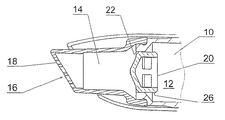
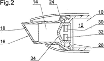
図1は、本発明の好ましい実施の形態による化粧品の塗布器具の第1の動作状態を示す概略的拡大縦断面図である。図2は、図1の塗布器具の第2の動作状態を示す。 FIG. 1 is a schematic enlarged longitudinal sectional view showing a first operation state of a cosmetic applicator according to a preferred embodiment of the present invention. FIG. 2 shows a second operating state of the applicator of FIG.
図示の塗布器具は、例えば口紅12のような液状化粧品が収容されている収納部10を備えている。この収納部10は、搬送路14を介して塗布器具の作用面16に連通している。作用面16には、そのうちの一つが符号18で示されている複数の流出口が設けられている。
The illustrated applicator includes a
図1に示された動作状態(第1の動作状態)においては、収納部10の作用面16に向いている側が、開口部22に嵌められた栓(防壁)20によって閉塞されている。第1の動作状態においては、開口部22の内壁に対してシール関係にあるシーリング隆起24がシール状態を保っている。図1に示された第1の動作状態においては、栓20が収納部10を閉塞しているので、口紅12は作用面の流出口18を通過することが不可能である。
In the operation state (first operation state) shown in FIG. 1, the side facing the
図2に示された第2の動作状態においては、栓20が、図1に示された第1の動作状態に対して作用面16に向かう方向に変位される。この変位は、周囲に延びる突出部26が段部28に当接することによって制限される。
In the second operating state shown in FIG. 2, the
第2の動作状態(図2)においては、栓20はもはや収納部10をシールしていない。特に栓20は、第2の動作状態において、収納部10から搬送路14を通じて流出口18に至る経路を開く通路30,32を備えている。この場合、第2の動作状態においては、通路30,32が通路22と部分的にのみオーバーラップするが、栓20は開口部22から僅かに突出するだけである。
In the second operating state (FIG. 2), the
第2の動作状態においては、口紅12は、収納部10から流出口18までの経路を、通路30,32を通って「回り道」をする。この回り道により、流速および壁に対する栓20の摩擦が増大し、その結果、材料(口紅)に強い渦が生じて分離しがちな材料が混合される。
In the second operating state, the
収納部10内に圧力が加わると、口紅12は、収納部10から搬送路14を介して流出口18を備えた作用面16に運ばれる。栓20が第1の動作状態にあるときには、初めはこのような圧力は口紅12を移動させる原因にはならないが、栓20を図1に示された第1の動作状態から図2に示された第2の動作状態まで変位させる原因となる。このような圧力は、例えば回動機構(図示せず)の作動によっても発生させることができるが、より具体的に言うと、この圧力は、いわゆる最初の回転時に、すなわち、収納部10内の口紅12で満たされていないデッドスペースを無くす動作時に既に発生している。栓20が一旦第2の動作状態(図2)になると、収納部10内の圧力は減少するが、通路30,32が存在しているので、栓20はもはや第1の動作状態(図1)には戻れない。換言すれば、栓20の第1の動作状態(図1)から第2の動作状態(図2)への変位は非可逆的である。
When pressure is applied to the
第2の動作状態(図2)において、通路30,32は、口紅12が収納部10から流出口18に向かって移動するのを可能にはするが、壷状の栓20の底壁34は、この塗布器具が揺動された結果、口紅12が偶発的に収納部10から流出口18に移動するのを防止するのに十分である。より具体的に言うと、上記揺動は口紅12の直線的な移動の引金になるだけで、通路30,32を抜けて壷状の栓20の底壁34を巡る「回り道」を通る移動の引金にはならない。
In the second operating state (FIG. 2), the
上述した本発明の特徴、請求項および図面は、個々に、または組み合わせて、本発明の種々の実施の形態を実施するために不可欠なものである。 The features of the invention, the claims and the drawings described above are essential for carrying out the various embodiments of the invention either individually or in combination.
10 収納部
12 口紅(製品)
14 搬送路
16 作用面
18 流出口
20 栓(防壁)
22 開口部
30,32 通路
10
14
22
Claims (6)
前記製品(12)が自由形態で収容される収納部(10)と、前記製品(12)のための流出口(18)とを備えたものにおいて、
少なくとも一つの動作状態において、前記製品(12)のための、前記収納部(10)から前記流出口(18)への直線的な通路を少なくとも部分的に封鎖する、前記直線的な通路を横切る壁(34)と、該直線的な通路に平行な側壁とを備えた壷形状をなし、該側壁を横切る通路(30,32)を備えた防壁(20)を備え、
前記防壁(20)は、前記収納部(10)から前記流出口(18)への通路を第1の程度に封鎖する第1の動作状態と、前記通路を前記第1の程度よりも少ない第2の程度に封鎖する第2の動作状態との、少なくとも二つの動作状態を採ることが可能であり、これにより、前記防壁(20)は、前記第1の動作状態から前記第2の動作状態へ変位可能であるが、その逆は不可能なものであることを特徴とする塗布器具。An applicator for a liquid, gel, paste or powder product (12) comprising:
In the thing provided with the accommodating part (10) in which the said product (12) is accommodated in a free form, and the outflow port (18) for the said product (12),
In at least one operating state, across the straight passage for at least partially blocking the straight passage for the product (12) from the storage (10) to the outlet (18). Comprising a wall (34) and a barrier (20) with a passage (30, 32) crossing the side wall in the form of a bowl with a side wall parallel to the straight passage ;
The barrier (20) has a first operation state in which a passage from the storage portion (10) to the outlet (18) is blocked to a first degree, and the passage is less than the first degree. It is possible to take at least two operating states, such as a second operating state that is blocked to a degree of 2, so that the barrier (20) is moved from the first operating state to the second operating state. An applicator characterized in that it is displaceable, but not vice versa.
Applications Claiming Priority (2)
| Application Number | Priority Date | Filing Date | Title |
|---|---|---|---|
| DE202004008901U DE202004008901U1 (en) | 2004-06-04 | 2004-06-04 | applicator |
| PCT/EP2005/005569 WO2005118152A1 (en) | 2004-06-04 | 2005-05-23 | Applicator device with barrier |
Publications (3)
| Publication Number | Publication Date |
|---|---|
| JP2007528244A JP2007528244A (en) | 2007-10-11 |
| JP2007528244A5 JP2007528244A5 (en) | 2009-10-22 |
| JP4596552B2 true JP4596552B2 (en) | 2010-12-08 |
Family
ID=34968242
Family Applications (1)
| Application Number | Title | Priority Date | Filing Date |
|---|---|---|---|
| JP2007502314A Expired - Fee Related JP4596552B2 (en) | 2004-06-04 | 2005-05-23 | Applicator with barrier |
Country Status (6)
| Country | Link |
|---|---|
| JP (1) | JP4596552B2 (en) |
| KR (1) | KR100896042B1 (en) |
| BR (1) | BRPI0507146A (en) |
| DE (1) | DE202004008901U1 (en) |
| MX (1) | MXPA06013965A (en) |
| WO (1) | WO2005118152A1 (en) |
Families Citing this family (4)
| Publication number | Priority date | Publication date | Assignee | Title |
|---|---|---|---|---|
| EP2848550B1 (en) | 2012-05-09 | 2017-11-22 | Nihon Tenganyaku Kenkyusyo Co., Ltd. | Discharging container equipped with filter |
| JP5066297B1 (en) * | 2012-05-09 | 2012-11-07 | 大成化工株式会社 | Cap for liquid container |
| JP5066296B1 (en) * | 2012-05-09 | 2012-11-07 | 株式会社日本点眼薬研究所 | Discharge container with filter |
| US9788993B2 (en) | 2012-05-09 | 2017-10-17 | Taisei Kako Co., Ltd. | Mouth cap for liquid container |
Family Cites Families (8)
| Publication number | Priority date | Publication date | Assignee | Title |
|---|---|---|---|---|
| US2715236A (en) * | 1953-04-07 | 1955-08-16 | Tereno Jack | Liquid ejector and applicator |
| JPS5117156U (en) * | 1974-07-24 | 1976-02-07 | ||
| US4674659A (en) * | 1978-04-24 | 1987-06-23 | Leeds And Micallef | Universal sequential dispensing pump system |
| JPS59155184U (en) * | 1983-04-05 | 1984-10-18 | ぺんてる株式会社 | Applicator with valve |
| JPH0719584Y2 (en) * | 1989-04-14 | 1995-05-10 | グンゼ産業株式会社 | Cartridge type applicator |
| JP2512078Y2 (en) * | 1989-06-30 | 1996-09-25 | ぺんてる株式会社 | Ink tank opening structure |
| FR2744105B1 (en) * | 1996-01-25 | 1998-03-06 | Oreal | DOSER BOTTLE |
| FR2810858B1 (en) * | 2000-06-28 | 2003-01-10 | Oreal | DISTRIBUTION TIP COMPRISING TWO ASSEMBLED PARTS AND A FLOCKING COATING |
-
2004
- 2004-06-04 DE DE202004008901U patent/DE202004008901U1/en not_active Expired - Lifetime
-
2005
- 2005-05-23 WO PCT/EP2005/005569 patent/WO2005118152A1/en not_active Ceased
- 2005-05-23 KR KR1020067023258A patent/KR100896042B1/en not_active Expired - Fee Related
- 2005-05-23 MX MXPA06013965A patent/MXPA06013965A/en active IP Right Grant
- 2005-05-23 JP JP2007502314A patent/JP4596552B2/en not_active Expired - Fee Related
- 2005-05-23 BR BRPI0507146-1A patent/BRPI0507146A/en not_active IP Right Cessation
Also Published As
| Publication number | Publication date |
|---|---|
| WO2005118152A1 (en) | 2005-12-15 |
| BRPI0507146A (en) | 2007-06-19 |
| JP2007528244A (en) | 2007-10-11 |
| KR20070000510A (en) | 2007-01-02 |
| MXPA06013965A (en) | 2007-02-08 |
| DE202004008901U1 (en) | 2005-10-13 |
| KR100896042B1 (en) | 2009-05-11 |
Similar Documents
| Publication | Publication Date | Title |
|---|---|---|
| JP5047183B2 (en) | One way valve assembly | |
| EP3287039B1 (en) | Cosmetic container having hiding/revealing pump outlet | |
| WO2016000054A1 (en) | Valve mechanism with applicator tip for cosmetic containers | |
| TW200619097A (en) | Reclosable container lid | |
| ATE260827T1 (en) | CLOSURE DEVICE WITH A DISPENSING VALVE | |
| JP2014522255A5 (en) | ||
| BR9910388A (en) | Composition conservation device for contact lens care and contact lens case | |
| JP4596552B2 (en) | Applicator with barrier | |
| KR101670774B1 (en) | Capsule type container having multiple space | |
| EP0692313A3 (en) | Fluid dispenser | |
| US20050281609A1 (en) | Applicator device | |
| JPS6053817A (en) | Quantity regulator | |
| JP2005041579A5 (en) | ||
| DE50012540D1 (en) | DEVICE FOR DISTRIBUTING A FLOWABLE PRODUCT FROM A CONTAINER | |
| KR20060136480A (en) | Applicator device with barrier | |
| JP4949751B2 (en) | Cosmetic applicator | |
| TW200611656A (en) | Cosmetics dispenser container fitment | |
| ATE417526T1 (en) | APPLICATION DEVICE | |
| US555318A (en) | Oil-can | |
| KR102307992B1 (en) | A cosmetic vessel with mixing different contents | |
| JP4726596B2 (en) | Two-component mixing container | |
| JP2025132639A (en) | discharge container | |
| FR3071138B1 (en) | PACKAGING AND DISTRIBUTION ASSEMBLY FOR A PRODUCT, IN PARTICULAR COSMETIC, INCLUDING A RECALL BODY TO FORCE THE ASSEMBLY IN A CLOSED POSITION | |
| KR200294043Y1 (en) | Openning Structure Of Powder inside Cosmetics Container | |
| WO2006030022A3 (en) | Liquid dispenser |
Legal Events
| Date | Code | Title | Description |
|---|---|---|---|
| A131 | Notification of reasons for refusal |
Free format text: JAPANESE INTERMEDIATE CODE: A131 Effective date: 20090623 |
|
| A524 | Written submission of copy of amendment under article 19 pct |
Free format text: JAPANESE INTERMEDIATE CODE: A524 Effective date: 20090901 |
|
| A131 | Notification of reasons for refusal |
Free format text: JAPANESE INTERMEDIATE CODE: A131 Effective date: 20100316 |
|
| A521 | Request for written amendment filed |
Free format text: JAPANESE INTERMEDIATE CODE: A523 Effective date: 20100611 |
|
| TRDD | Decision of grant or rejection written | ||
| A01 | Written decision to grant a patent or to grant a registration (utility model) |
Free format text: JAPANESE INTERMEDIATE CODE: A01 Effective date: 20100907 |
|
| A01 | Written decision to grant a patent or to grant a registration (utility model) |
Free format text: JAPANESE INTERMEDIATE CODE: A01 |
|
| A61 | First payment of annual fees (during grant procedure) |
Free format text: JAPANESE INTERMEDIATE CODE: A61 Effective date: 20100917 |
|
| R150 | Certificate of patent or registration of utility model |
Free format text: JAPANESE INTERMEDIATE CODE: R150 |
|
| FPAY | Renewal fee payment (event date is renewal date of database) |
Free format text: PAYMENT UNTIL: 20131001 Year of fee payment: 3 |
|
| LAPS | Cancellation because of no payment of annual fees |